modular clamping rail system sl120 & sl080...zeroclamp modular clamping rail system operating...
TRANSCRIPT

O r i g i n a l I n s t a l l a t i o n a n d O p e r a t i n g I n s t r u c t i o n s
Modular Clamping Rail System SL120 & SL080

Copyright ZEROCLAMP® Modular Clamping Rail System Installation and Operating Instructions. These operating instructions are the property of ZeroClamp® GmbH, D-82057 Icking Unauthorized reproduction, even of extracts, is not permitted. Issue: 8/3/2017

List of contents 1. General matters .................................................................................................... 2
1.1 Use of the installation and operating instructions .................................................. 2 1.2 Customer Service contact information .................................................................... 2 1.3 Warranty ..................................................................................................................... 2 1.4 Scope of supply ......................................................................................................... 2 1.5 Declaration of conformity ......................................................................................... 3
2. Safety ..................................................................................................................... 4
2.1 General safety instructions ....................................................................................... 4 2.2 Use for the intended purpose ................................................................................... 6 2.3 Period of use of the subsidiary zero point clamping system ................................. 6 2.4 Structural modifications ............................................................................................ 6 2.5 Training the operators ............................................................................................... 6 2.6 Operational environment .......................................................................................... 7
3. Technical data ....................................................................................................... 7
3.1 Clamping forces ........................................................................................................ 7 3.2 Operating temperature .............................................................................................. 7 3.3 Sizes and weights ...................................................................................................... 8 3.4 Clamping widths SL120............................................................................................. 8 3.5 Clamping widths SL080............................................................................................10
4. Operation ............................................................................................................. 12
4.1 View ...........................................................................................................................12 4.2 System accuracy ......................................................................................................13 4.3 Assembly ..................................................................................................................13
4.3.1 When using on a machine table .......................................................................................... 13 4.3.2 When using on the zero point clamping system .................................................................. 14
4.3.2.1 Clamping by one pot..................................................................................................... 17 4.3.3 Fastening of a clamping jaw ................................................................................................ 21
4.4 Tools required ...........................................................................................................22
5. Accessories ........................................................................................................ 23
5.1 Accessories SL120 ...................................................................................................23 5.1.1 Side clamp ........................................................................................................................... 23 5.1.2 Parallel clamping jaw ........................................................................................................... 24 5.1.3 Pull-down jaw ....................................................................................................................... 24 5.1.4 Fixed jaw .............................................................................................................................. 24 5.1.5 Cross connector ................................................................................................................... 24 5.1.6 Stepped jaw ......................................................................................................................... 24 5.1.7 Clamping pot socket ............................................................................................................ 25 5.1.8 Serrated top jaw, steel ......................................................................................................... 25 5.1.9 Magnetic workpiece stop ..................................................................................................... 25 5.1.10 Base jaw, 5-AXIS (pair) ..................................................................................................... 25 5.1.11 Grip facing jaw (pair) .......................................................................................................... 25 5.1.12 Base jaw with pivot function ............................................................................................... 25 5.1.13 Fixed base jaw ................................................................................................................... 26 5.1.14 Grip insert .......................................................................................................................... 26

5.1.15 Clamping insert, smooth .................................................................................................... 26 5.1.16 Grip facing jaw ................................................................................................................... 26 5.1.17 HM facing jaw .................................................................................................................... 26 5.1.18 Magnetic Strip .................................................................................................................... 27 5.1.19 Base jaw ............................................................................................................................ 27 5.1.20 Top jaws ............................................................................................................................. 27 5.1.21 Facing jaws ........................................................................................................................ 27 5.1.22 Pull-down facing jaw .......................................................................................................... 27
5.2 Accessories SL080 ...................................................................................................28 5.2.1 Side clamp ........................................................................................................................... 28 5.2.2 Pull-down jaw 26 .................................................................................................................. 28 5.2.3 Pull-down jaw 26 Duo .......................................................................................................... 28 5.2.4 Pull-down jaw 48 .................................................................................................................. 29 5.2.5 Pull-down jaw 80 .................................................................................................................. 29 5.2.6 Parallel clamping jaw 48 ...................................................................................................... 29 5.2.7 Parallel clamping jaw 80 ...................................................................................................... 29 5.2.8 Fixed jaw 26 ......................................................................................................................... 29 5.2.9 Fixed jaw 48 ......................................................................................................................... 30 5.2.10 Fixed jaw 80 ....................................................................................................................... 30 5.2.11 Form-fit jaw ........................................................................................................................ 30 5.2.12 Centering clamping fixture ................................................................................................. 30 5.2.13 Base jaw ............................................................................................................................ 30 5.2.14 Cross connector ................................................................................................................. 31 5.2.15 Grip and HM facing jaw ..................................................................................................... 31 5.2.16 Serrated facing jaw ............................................................................................................ 31 5.2.17 Magnetic Strip 74 ............................................................................................................... 31 5.2.18 Magnetic Strip 94 ............................................................................................................... 32 5.2.19 Workpiece stop .................................................................................................................. 32 5.2.20 Facing jaw .......................................................................................................................... 32 5.2.21 Top jaw .............................................................................................................................. 32 5.2.22 Supporting plate ................................................................................................................. 32 5.2.23 Pull-down facing jaw .......................................................................................................... 33
6. Spare parts .......................................................................................................... 33
7. Maintenance operations ..................................................................................... 34
7.1 Extraction of liquids .................................................................................................34 7.2 Cleaning and care .....................................................................................................34 7.3 Storage ......................................................................................................................35
8. Residual risks ..................................................................................................... 35
9. Concluding remarks ........................................................................................... 35
10. Index .................................................................................................................. 36
11. Appendix ........................................................................................................... 37
ZeroClamp Modular Clamping Rail System Operating Instructions 2
1. General matters
1.1 Use of the installation and operating instructions Dear customer, Many thanks for deciding to purchase our products. These installation and operating instructions contain useful information allowing you to familiarize yourself with your clamping system before starting to use it for its intended purpose under the specified operating conditions. They contain important instructions to ensure functionally correct and cost-effective installation and operation. The operating instructions have been created for use by installation, operating and maintenance staff, and must always be kept to hand at the place of use of the clamping system. You have chosen a high-quality clamping system which operates at extremely high precision. In the interests of product improvement we reserve the right to make changes in respect of versions, dimensions and materials. Of course, we remain available to you at all times for after-sales service. Please contact us using the information set out below.
1.2 Customer Service contact information ZeroClamp GmbH Wadlhausen 14 D-82057 Icking, Germany Tel. +49 (0) 8178-90998-0 [email protected]
1.3 Warranty The warranty is 12 months from the date of delivery from the works, provided the system is used for its intended purpose in 1-shift operation. These operating instructions supersede any previous versions. The current version of the operating instructions is available for download at: www.zeroclamp.com
1.4 Scope of supply The scope of supply includes:
• 1x clamping rail of corresponding size • 1x ruler with two mounting screws (mounted) • The scope of supply of the Modular Clamping Rail System SL080 with 260
mm length in particular includes support plates (2x), countersunk screws and locating pins (4x each)

ZeroClamp Modular Clamping Rail System Operating Instructions 3
1.5 Declaration of conformity The manufacturer: ZeroClamp GmbH Wadlhausen 14 D-82057 Icking, Germany hereby declares that the following products: Product designation: Modular Clamping Rail System Type designation: SL120 and SL080 Build year: 2013 comply with the following essential requirements of the Machines Directive (2006/42/EC): The following standards were applied: DIN EN ISO 12100 Safety of machinery - General principles for design, risk
assessment and risk reduction ISO 16156 Safety Machine tools safety – Safety requirements for the
design and construction of work holding chucks ISO 19719 Machine tools — Work holding chucks — Vocabulary The incomplete machine may not be brought into use until it has been incorporated into a machine and the machine into which it has been incorporated satisfies the provisions of the Machines Directive (2006/42/EC). The manufacturer undertakes on request to communicate by electronic means the special documents relating to the incomplete machine. The special technical documents relating to the machine were created in accordance with Appendix VII Part B. Name of the authorized person for documentation: Klaus Hofmann Address of the authorized person for documentation: see manufacturer's address Icking, May 2, 2013 Klaus Hofmann, Managing Director Date Signatory and details of signatory Signature

ZeroClamp Modular Clamping Rail System Operating Instructions 4
2. Safety
2.1 General safety instructions
Warning! For use on the zero point clamping system If the forces acting on the clamping rail become too great, due to machining of a workpiece, the clamping stud might be torn from the clamping pot even in the clamped state. Do not overload the zero point clamping system. Make an estimate of the forces to be expected. Use additional safety devices, e.g., monitoring devices and safety guards.
Warning! For use on the zero point clamping system
The zero point clamping system will only clamp the clamping rail reliably if the clamping stud and the clamping pot lie flat against each other. Even slight impurities between the contact surfaces, or a tilted position will compromise the clamping effect. Furthermore, surface inaccuracies caused by wear will also compromise the clamping effect. Before clamping the pieces, always thoroughly clean the contact surfaces between clamping stud and clamping pot! Verify the exact concentric alignment of clamping stud and clamping pot. Regularly check the clamping force of the zero point clamping system, using a pull-out force tester. Use the subsidiary zero point clamping system for a maximum of 1,000,000 clamping cycles.
Warning!
When the clamping jaws are actuated, the skin of the fingers or the fingers might be crushed. Do not reach between the clamping jaws, or between the clamping jaw and the workpiece.

ZeroClamp Modular Clamping Rail System Operating Instructions 5
Warning!
When the clamping system is fastened, the skin of the fingers or the fingers might be crushed. Do not reach between the clamping rail and the machine table / zero point clamping system.
Warning!
The clamping rail will only be reliably fastened to the machine table if all contact surfaces are completely clean. Even slight impurities between the contact surfaces, or a tilted position will compromise the clamping effect. Use only original parts, or standard parts that are approved by the manufacturer.
Furthermore, surface inaccuracies caused by wear will also compromise the clamping effect. Before clamping workpieces, always thoroughly clean the contact surfaces between the clamping rail and the machine table.
Warning! For use on the zero point clamping system
Accidental actuation of the subsidiary zero point clamping system might lead to unintentional releasing of the entire clamping fixture. Disconnect the zero point clamping system from the compressed air supply before you undertake installation, adjustment, maintenance or set-up work. During operation, secure the subsidiary zero point clamping system against unintentional releasing by using suitable safety devices for the compressed air supply.
Warning!
Clamping systems might be very heavy. When you build your own clamping assemblies, make sure that they can be fastened in a suitable way in order to be lifted with handling devices or cranes. Give particular attention to this point if the clamping systems weigh 20 kg and more.

ZeroClamp Modular Clamping Rail System Operating Instructions 6
2.2 Use for the intended purpose
The clamping system must only be used for clamping workpieces.
Use for the intended purpose includes compliance with the conditions specified by the manufacturer in respect of installation, commissioning, operation, ambient conditions and maintenance.
Any use that is not within these conditions ranks as improper use. The manufacturer accepts no responsibility for damage resulting from improper use. Before using the clamping system in an environment with abrasive dusts, caustic or aggressive vapors or liquids, you must obtain approval by ZeroClamp®.
2.3 Period of use of the subsidiary zero point clamping system The zero point clamping system mechanism is designed for a maximum life span of 1,000,000 clamping cycles.
2.4 Structural modifications For reasons of safety, unauthorized changes and modifications of the clamping rail are prohibited! When exchanging defective parts, use only original parts, or standard parts that are approved by the manufacturer.
2.5 Training the operators The operators must have received instruction on the following topics: • Functionality and operation of the clamping rail • Maintaining the clamping forces • Servicing and cleaning work All persons responsible for the installation, commissioning and maintenance of the tester must have read and understood the complete operating instructions, especially Section 2 "Safety". We recommend that the operating company obtains signatures to this effect. Installation, removal, connection and commissioning may be performed only by authorized personnel. Do not use operating techniques which adversely affect the functionality and operational safety of the clamping system.

ZeroClamp Modular Clamping Rail System Operating Instructions 7
2.6 Operational environment The clamping rail system is not suitable for the following operational environments:
• Abrasive dusts, • Caustic or aggressive liquids and vapors.
3. Technical data
3.1 Clamping forces
When releasing the parallel clamping jaws, make sure not to exceed an initial torque of 10 Nm for the spindle.
The parallel clamping jaws SL080 (from rev. 5) and SL120 (from rev. 4) have the same releasing moments such as the max clamping moments.
Clamping force Torque Pull-down jaws
Torque Parallel clamping jaws
Torque Duo pull-down jaws
(when using both jaws)
SL
080
KN Nm Nm Nm 5 6.0 5.0 6.0 10 12.0 10.0 8.0 15 17.5 15.0 10.0 20 25.0 20.0 14.0
SL
120
10 17 10 - 20 30 20 - 30 50 30 - 40 - 40 -
Note:
All values are intended for reference. They are only standard values and do not imply any guarantee (depending on the material). They are only guaranteed under optimum conditions (clean, greased contact surfaces and threads).
Max. 10 Nm
When the tension is released, the initial torque might be greater than 10 Nm. However, the torque will drop again immediately.

ZeroClamp Modular Clamping Rail System Operating Instructions 8
3.2 Operating temperature Minimum 15 °C Maximum 40 °C
3.3 Sizes and weights SL120
Length in mm 300 600 Height in mm 60 60 Width in mm 120 120
Order No.: 20254 16221 Weight in kg 9.3 19
SL080
Length in mm 260 400 500 600 Height in mm 35 35 35 35 Width in mm 80 80 80 80
Order No.: 13834 13833 14269 13408 Weight in kg 5.2 7.7 9.7 11.6
Warning!
The complete clamping system might be very heavy. When you build your own clamping systems, make sure that they can be fastened in a suitable way in order to be lifted with handling devices or cranes.
3.4 Clamping widths SL120
Clamping rail length in mm 300 600 800 Clamping range in mm 0-90 0-390 0-590
With pull-down jaw Jaw stroke 4.5 mm

ZeroClamp Modular Clamping Rail System Operating Instructions 9
Clamping rail length in mm 300 600 800 Clamping range in mm 0-90 0-390 0-590
Clamping rail length in mm 300 600 800 Clamping range in mm 90-165 90-465 90-665
Clamping rail length in mm 300 600 800 Clamping range in mm 10-60 10-60 10-60
Clamping rail length in mm 300 600 800 Clamping range in mm 30-220 30-520 30-720 Clamping range in mm (round material)
> Ø 30 > Ø 30 > Ø 30
With parallel clamping jaw Jaw stroke 4 mm
With steel serrated top jaws
With base jaw, 5-AXIS
With grip top jaw

ZeroClamp Modular Clamping Rail System Operating Instructions 10
Note:
When using facing jaws, the clamping widths are reduced.
Warning!
The position of the clamping jaw (with fully retracted clamping mechanism) schould be as close as possible to the workpiece that be clamped. A 2 mm grid of the clamping rail is available.
If this are not observed, a lost of clamping force can occur.
Clamping rail length in mm 300 600 800 Clamping range in mm 70-160 70-460 70-660
Clamping rail length in mm 300 600 800 Center distance in mm 160-180 160-480 160-680
With stepped jaw
With cross connector

ZeroClamp Modular Clamping Rail System Operating Instructions 11
3.5 Clamping widths SL080 With pull-down jaw Pull-down jaw 26 and duo jaw stroke 3.5 mm Pull-down jaw 48 and 80 jaw stroke 4.0 mm
Clamping rail length in mm 260 400 500 600 Clamping range in mm 0-145 0-285 0-385 0-485
With parallel clamping jaw Jaw stroke 3.5 mm
Clamping rail length in mm 260 400 500 600 Clamping range in mm 0-135 0-275 0-375 0-475
With cross connector
Clamping rails length in mm 260 400 500 600 Center distance in mm 116-178 116-318 116-418 116-518
Note:
When using facing jaws, the clamping widths are reduced.
Warning!
The position of the clamping jaw (with fully retracted clamping mechanism) schould be as close as possible to the workpiece that be clamped. A 2 mm grid of the clamping rail is available.
If this are not observed, a lost of clamping force can occur.

ZeroClamp Modular Clamping Rail System Operating Instructions 12
4. Operation 4.1 View
(Fig.: Modular Clamping Rail System SL120) The Modular Clamping Rail Systems SL120 and SL080 are clamping rail systems that can be used universally and flexibly, due to their wide range of jaw systems. The Modular Clamping Rail Systems are used for the positive-locking clamping of blanks, and of machined workpieces. Both Modular Clamping Rail Systems can be mounted on conventional machine tables, or on the zero point clamping system by ZeroClamp® GmbH. For use with the zero point clamping system, special bolts are required (not included in delivery).

ZeroClamp Modular Clamping Rail System Operating Instructions 13
4.2 System accuracy Modular Clamping Rail Systems attain a pairing accuracy of ± 0.03 mm.
4.3 Assembly The Modular Clamping Rail System must always rest completely on the machine table or on the clamping pots. Therefore, surfaces must be cleaned before fastening. Fasten the clamping rails at two points at least. When using the zero point clamping system, you can also use a clamping point for fastening. In this case, indexing is obligatory in order to prevent twisting of the clamping rail. However, the manufacturer recommends clamping by at least two pots, because higher torques can thus be accommodated. In order to prevent sagging with certain types of clamping fixtures, use a suitable supporting structure.
4.3.1 When using on a machine table The clamping rails can be used both on the zero point clamping system and on the machine table (40 / 50 mm grid). The appropriate fastening material (Side clamp, Order No. 19296) is not included in the delivery. Use only original parts, or standard parts that are approved by the manufacturer. The rails can also be fastened by means of fitting screws.
(Fig.: Special supporting structure to prevent sagging)

ZeroClamp Modular Clamping Rail System Operating Instructions 14
(Fig.: Example illustration of SL080 fastened on machine table with fitting screws)
When using several clamping rails in parallel, make sure that the chamfers (5x45) are always positioned on the same side.
Warning!
Clean all contact surfaces thoroughly in order to achieve a precise fit.
Warning!
Fasten the clamping rail on the machine table at two points at least. Use only original parts, or standard parts that are approved by the manufacturer.
Warning!
When the clamping system is fastened, the skin of the fingers or the fingers might be crushed. Do not reach between the clamping rail and the machine table.
4.3.2 When using on the zero point clamping system
ZeroClamp Modular Clamping Rail System Operating Instructions 15
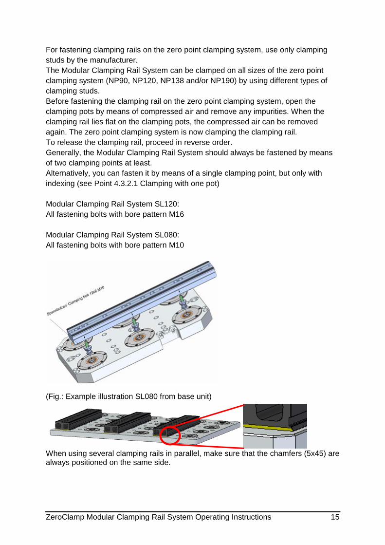
For fastening clamping rails on the zero point clamping system, use only clamping studs by the manufacturer. The Modular Clamping Rail System can be clamped on all sizes of the zero point clamping system (NP90, NP120, NP138 and/or NP190) by using different types of clamping studs. Before fastening the clamping rail on the zero point clamping system, open the clamping pots by means of compressed air and remove any impurities. When the clamping rail lies flat on the clamping pots, the compressed air can be removed again. The zero point clamping system is now clamping the clamping rail. To release the clamping rail, proceed in reverse order. Generally, the Modular Clamping Rail System should always be fastened by means of two clamping points at least. Alternatively, you can fasten it by means of a single clamping point, but only with indexing (see Point 4.3.2.1 Clamping with one pot) Modular Clamping Rail System SL120: All fastening bolts with bore pattern M16 Modular Clamping Rail System SL080: All fastening bolts with bore pattern M10
(Fig.: Example illustration SL080 from base unit)
When using several clamping rails in parallel, make sure that the chamfers (5x45) are always positioned on the same side.

ZeroClamp Modular Clamping Rail System Operating Instructions 16
Warning!
Clean all contact surfaces thoroughly in order to achieve a precise fit.
Warning!
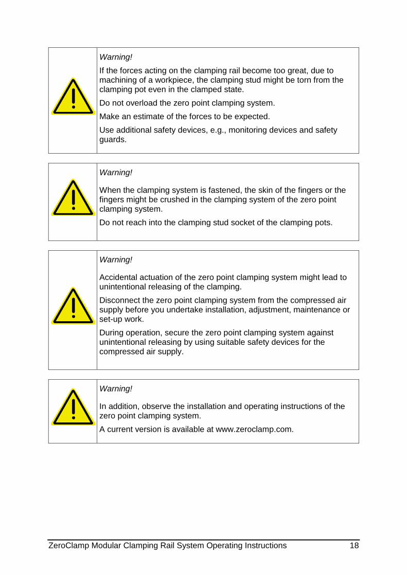
When the clamping system is fastened, the skin of the fingers or the fingers might be crushed in the clamping system of the zero point clamping system. Do not reach into the clamping stud socket of the clamping pots.
Warning!
Accidental actuation of the zero point clamping system might lead to unintentional releasing of the clamping fixture. Disconnect the zero point clamping system from the compressed air supply before you undertake installation, adjustment, maintenance or set-up work. During operation, secure the zero point clamping system against unintentional releasing by using suitable safety devices for the compressed air supply.
Warning! If the forces acting on the clamping rail become too great, due to machining of a workpiece, the clamping stud might be torn from the clamping pot even in the clamped state. Do not overload the zero point clamping system. Make an estimate of the forces to be expected. Use additional safety devices, e.g., monitoring devices and safety guards.
Warning!
In addition, observe the installation and operating instructions of the zero point clamping system. A current version is available at www.zeroclamp.com.

ZeroClamp Modular Clamping Rail System Operating Instructions 17
Note:
The manufacturer recommends fastening the rail by at least two clamping points, because higher torques can thus be accommodated compared to the use of indexing.
4.3.2.1 Clamping by one pot Generally, the Modular Clamping Rail System should always be fastened by means of two clamping pots at least. However, in case of the Modular Clamping Rail System SL080 with 260 mm length, many workpieces can be clamped by a single clamping point. For this purpose, two types of clamping fixtures are available. Clamping by one pot, with indexing
(Fig.: SL080 on clamping pot, with indexing)
Warning!
Clean all contact surfaces thoroughly in order to achieve a precise fit.
Use only with 2 indexing pins. Insert pins into the pot. Then put the clamping rail in position. The indexing pins protect the clamping fixture against turning.
ZeroClamp Modular Clamping Rail System Operating Instructions 18
Warning! If the forces acting on the clamping rail become too great, due to machining of a workpiece, the clamping stud might be torn from the clamping pot even in the clamped state. Do not overload the zero point clamping system. Make an estimate of the forces to be expected. Use additional safety devices, e.g., monitoring devices and safety guards.
Warning!
When the clamping system is fastened, the skin of the fingers or the fingers might be crushed in the clamping system of the zero point clamping system. Do not reach into the clamping stud socket of the clamping pots.
Warning!
Accidental actuation of the zero point clamping system might lead to unintentional releasing of the clamping. Disconnect the zero point clamping system from the compressed air supply before you undertake installation, adjustment, maintenance or set-up work. During operation, secure the zero point clamping system against unintentional releasing by using suitable safety devices for the compressed air supply.
Warning!
In addition, observe the installation and operating instructions of the zero point clamping system. A current version is available at www.zeroclamp.com.

ZeroClamp Modular Clamping Rail System Operating Instructions 19
Flexible clamping of complex workpieces If a complex workpiece is to be clamped by several rails, you can clamp the clamping rail on a pot in a way that it can be rotated (without indexing). This allows the clamping of e.g. flame cuts and cast parts.
(Fig.: Clamping examples)
In case of rotatable clamping, the manufacturer recommends the use of supporting plates. These plates absorb additional forces, and provide a firm seat on the clamping pot. The plates can be used only with the clamping rail system SL080 with 260 mm length. When ordering a clamping rail with 260 mm length, the supporting plates are included in the delivery.
Warning! When clamping parts, make sure that the workpiece cannot twist inside or together with the clamping fixture. The zero point clamping system without indexing is not capable of absorbing any torques. Therefore, always use at least two or more clamping rails or clamping pots with indexing in order to prevent twisting. It is not enough just to use two clamping rails to prevent a twisting of the clamping fixture. The clamping rails also must be positioned in the proper way.
Warning!
Clean all contact surfaces thoroughly in order to achieve a precise fit.

ZeroClamp Modular Clamping Rail System Operating Instructions 20
Warning! If the forces acting on the clamping rail become too great, due to machining of a workpiece, the clamping stud might be torn from the clamping pot even in the clamped state. Do not overload the zero point clamping system. Make an estimate of the forces to be expected. Use additional safety devices, e.g., monitoring devices and safety guards.
Warning!
When the clamping system is fastened, the skin of the fingers or the fingers might be crushed in the clamping system of the zero point clamping system. Do not reach into the clamping stud socket of the clamping pots.
Warning!
Accidental actuation of the zero point clamping system might lead to unintentional releasing of the clamping. Disconnect the zero point clamping system from the compressed air supply before you undertake installation, adjustment, maintenance or set-up work. During operation, secure the zero point clamping system against unintentional releasing by using suitable safety devices for the compressed air supply.
Warning!
In addition, observe the installation and operating instructions of the zero point clamping system. A current version is available at www.zeroclamp.com.
Note:
More case examples and videos can be found at www.zeroclamp.com

ZeroClamp Modular Clamping Rail System Operating Instructions 21
4.3.3 Fastening of a clamping jaw
Clamping jaws are coated with an anti-corrosion wax coating. During initial use, more force may therefore be required to operate the clamping mechanism. This is not a quality flaw. The protective wax coating can be removed by spraying with fine oil and then wiping it off. Do not use any pointed or sharp objects to remove the wax coating. All jaws can be fastened on the clamping rail rapidly, in a variety of ways, by means of the lateral clamping brackets. Never combine jaws from the two different systems. Only use clamping jaws that belong to the appropriate system. Clamping jaws can be positioned in a 2 mm pitch. They can be pre-positioned by means of a ruler on the upper side.
Warning!
Clean all contact surfaces thoroughly in order to achieve a precise fit.
Warning!
All clamping brackets must be fully folded in and clamped. They must not protrude. An incorrect seat might lead to unintentional releasing of the entire clamping fixture.
Loosen both screws. Fold brackets to the side, lift them off and place them to their new position
Fold in both clamping brackets to the stop, and tighten both screws to min.15 Nm, max. 16 Nm
Fold clamping brackets to the side, and place them to their position
ZeroClamp Modular Clamping Rail System Operating Instructions 22
Warning!
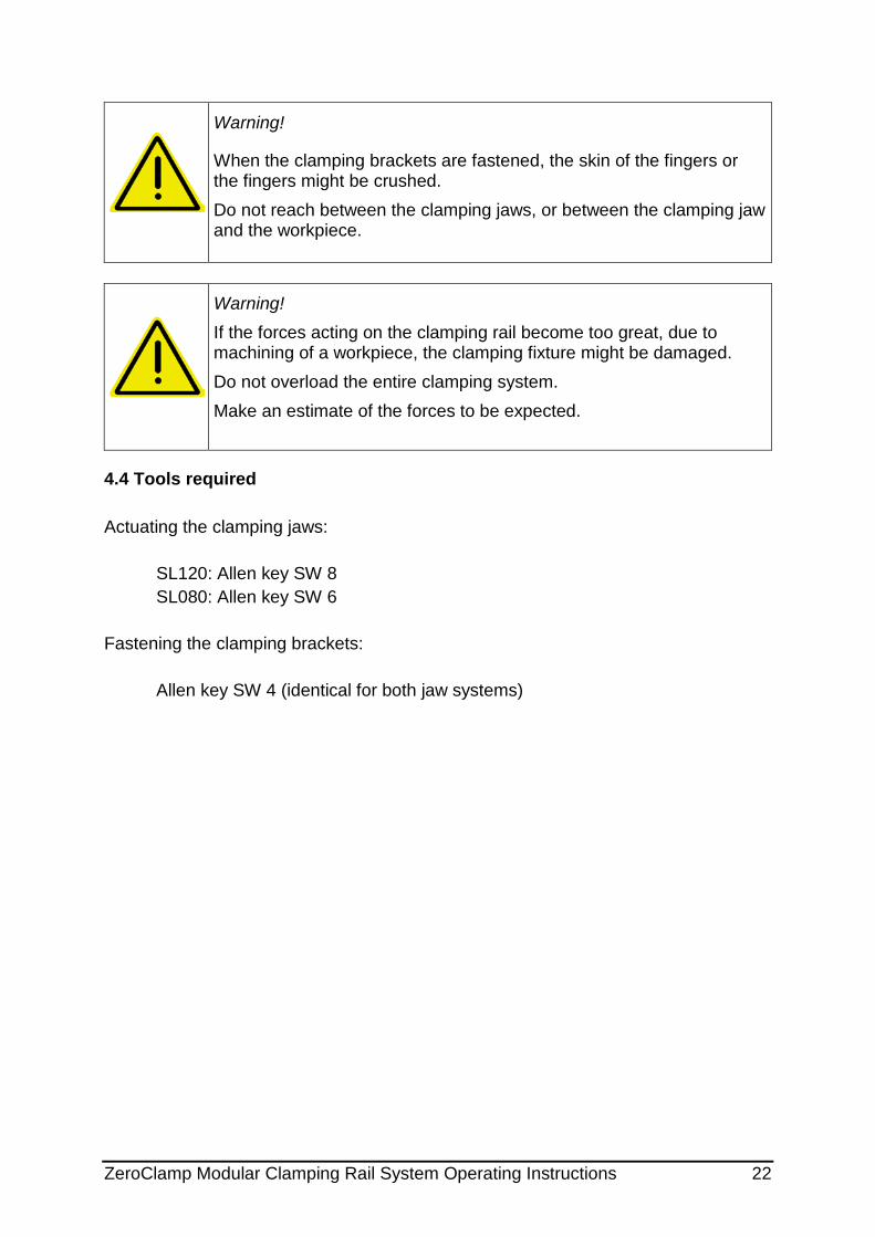
When the clamping brackets are fastened, the skin of the fingers or the fingers might be crushed. Do not reach between the clamping jaws, or between the clamping jaw and the workpiece.
Warning! If the forces acting on the clamping rail become too great, due to machining of a workpiece, the clamping fixture might be damaged. Do not overload the entire clamping system. Make an estimate of the forces to be expected.
4.4 Tools required
Actuating the clamping jaws: SL120: Allen key SW 8 SL080: Allen key SW 6 Fastening the clamping brackets: Allen key SW 4 (identical for both jaw systems)

ZeroClamp Modular Clamping Rail System Operating Instructions 23
5. Accessories A wide range of jaws and other accessories is available for the Modular Clamping Rail Systems. Use only original parts, or standard parts that are approved by the manufacturer. For a detailed description of available accessories, see the current catalog or www.zeroclamp.com.
Note:
All products are subject to continuous further development. Current accessories or modifications will be announced in time by the manufacturer at www.zeroclamp.com.
Warning!
When the clamping system is actuated, the skin of the fingers or the fingers might be crushed on the clamping jaws. Do not reach between the clamping jaws, or between the clamping jaws and the workpiece.
Warning!
Clean all contact surfaces thoroughly in order to achieve a precise fit.
Warning!
The complete clamping system might be very heavy. When you build your own clamping systems, make sure that they can be fastened in a suitable way in order to be lifted with handling devices or cranes.
5.1 Accessories SL120
5.1.1 Side clamp For conventional fastening of the clamping rail on the machine table.
ZeroClamp Modular Clamping Rail System Operating Instructions 24
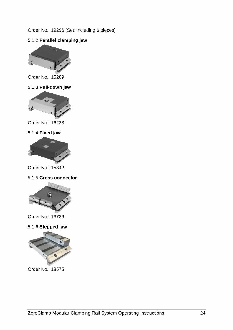
Order No.: 19296 (Set: including 6 pieces)
5.1.2 Parallel clamping jaw
Order No.: 15289
5.1.3 Pull-down jaw
Order No.: 16233
5.1.4 Fixed jaw
Order No.: 15342
5.1.5 Cross connector
Order No.: 16736
5.1.6 Stepped jaw
Order No.: 18575

ZeroClamp Modular Clamping Rail System Operating Instructions 25
5.1.7 Clamping pot socket
Order No.: 16240
5.1.8 Serrated top jaw, steel
Order No.: 17099
5.1.9 Magnetic workpiece stop
Order No.: 17908
5.1.10 Base jaw, 5-AXIS (pair)
Order No.: 15339
5.1.11 Grip facing jaw (pair)
Grip height in
mm 3.3 4.8
Order No.: 15341 20373
5.1.12 Base jaw with pivot function
Order No.: 15348
ZeroClamp Modular Clamping Rail System Operating Instructions 26
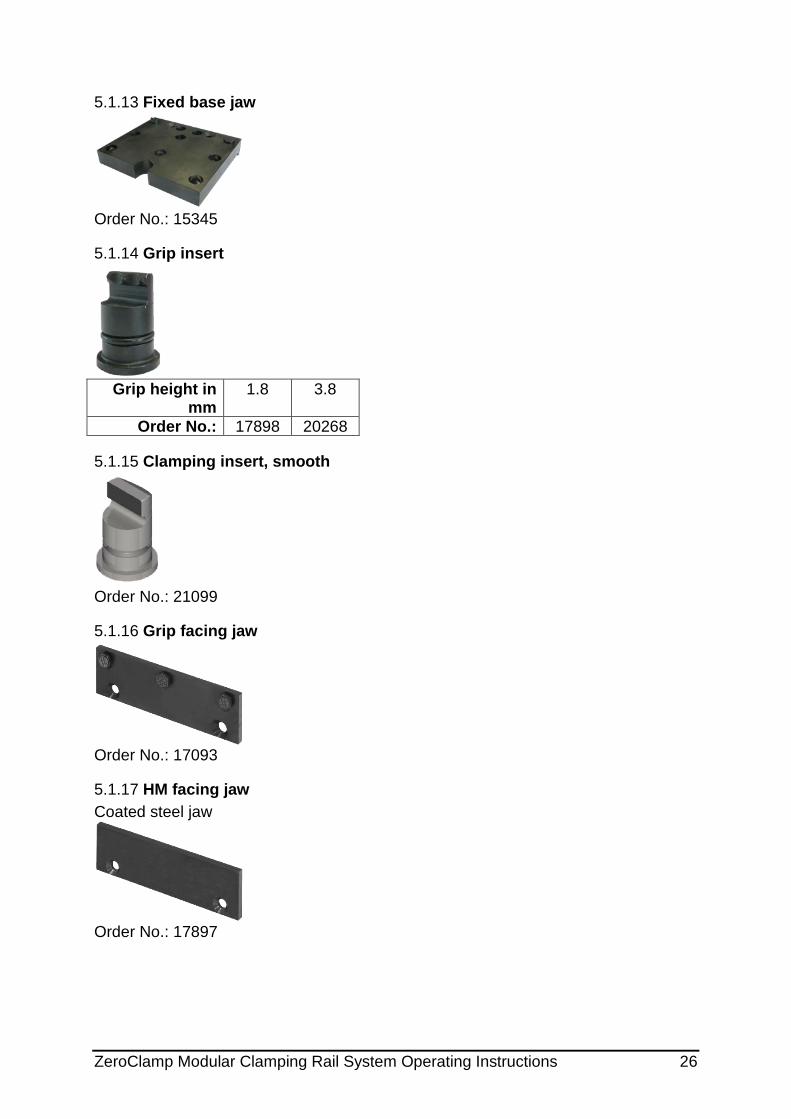
5.1.13 Fixed base jaw
Order No.: 15345
5.1.14 Grip insert
Grip height in
mm 1.8 3.8
Order No.: 17898 20268
5.1.15 Clamping insert, smooth
Order No.: 21099
5.1.16 Grip facing jaw
Order No.: 17093
5.1.17 HM facing jaw Coated steel jaw
Order No.: 17897

ZeroClamp Modular Clamping Rail System Operating Instructions 27
5.1.18 Magnetic Strip
Size width/height in mm 120/10 120/20 120/30 120/38
Order No.: 19391 19392 19393 19394
5.1.19 Base jaw
Order No.: 20765
5.1.20 Top jaws For own production of mold jaws (to fit on base jaw)
Material Aluminum Steel Version 1 ½ 1 ½
Order No.: 20778 20768 20780 20769
5.1.21 Facing jaws For own production of mold jaws (to fit on parallel clamping jaws)
Material Aluminum Steel Order No.: 20767 20766
5.1.22 Pull-down facing jaw The pull-down facing jaw can be used on fixed and parallel clamping jaws of size 120. It prevents the lifting off of the clamped workpiece.

ZeroClamp Modular Clamping Rail System Operating Instructions 28
Order No.: 22236
Fasten the facing jaw to the fixed or parallel clamping jaw by means of two Torx M6x16 screws (included in delivery). For this purpose, separate the facing jaw and then reassemble it. During this procedure, the facing jaw is held by magnets, tension springs and cylindrical pins. To open the jaw, fold out the two halves (see Fig.). The tension springs need not be removed for this. Avoid
damaging the jaw; do not use any pointed or sharp objects.
Warning!
After opening the jaw, clean all contact surfaces thoroughly. Make sure that all components are in their correct position.
5.2 Accessories SL080
5.2.1 Side clamp For conventional fastening of the clamping rail on the machine table.
Order No.: 19296 (Set including 6 pieces)
5.2.2 Pull-down jaw 26
Order No.: 13930
5.2.3 Pull-down jaw 26 Duo
Order No.: 13934

ZeroClamp Modular Clamping Rail System Operating Instructions 29
5.2.4 Pull-down jaw 48
Order No.: 13411
5.2.5 Pull-down jaw 80
Order No.: 14274
5.2.6 Parallel clamping jaw 48
Order No.: 13410
5.2.7 Parallel clamping jaw 80
Order No.: 14536
5.2.8 Fixed jaw 26
Order No.: 14369

ZeroClamp Modular Clamping Rail System Operating Instructions 30
5.2.9 Fixed jaw 48
Order No.: 13412
5.2.10 Fixed jaw 80
Order No.: 14280
5.2.11 Form-fit jaw
Order No.: 13936
5.2.12 Centering clamping fixture Observe the separate installation and operating instructions on www.zeroclamp.com
Order No.: 21838
5.2.13 Base jaw
Order No.: 14131

ZeroClamp Modular Clamping Rail System Operating Instructions 31
5.2.14 Cross connector
Order No.: 15421
5.2.15 Grip and HM facing jaw Coated steel jaw
(Fig.: Grip facing jaw 26 Order No.: 14482 and HM facing jaw 80 Order No.: 14373)
Size 26 48P 48NF 80 Grip Order No.: 14482 14565 14480 14484 HM Order No.: 14371 14576 14364 14373
48P = for parallel clamping jaw 48NF = for pull-down and fixed jaw
5.2.16 Serrated facing jaw
Order No.: 17010
5.2.17 Magnetic Strip 74
Size width/height in mm 74/10 74/15 74/20 74/25 74/30
Order No.: 14189 13575 14312 14314 14121

ZeroClamp Modular Clamping Rail System Operating Instructions 32
5.2.18 Magnetic Strip 94
Size width/height in mm 94/10 94/15
Order No.: 14006 13576
5.2.19 Workpiece stop
(Fig.: Fixed workpiece stop) Fixed Adjustable Magnetic
Order No.: 14119 14120 14116
5.2.20 Facing jaw For own production of mold jaws (to fit on parallel clamping jaw)
(Fig.: Top jaw, steel 80)
Material Aluminum Steel Version 48 80 48 80
Order No.: 14586 14590 14584 14588
5.2.21 Top jaw For own production of mold jaws (to fit on base jaw)
(Fig.: Top jaw, steel)
Material Aluminum Steel Order No.: 14134 14346
5.2.22

ZeroClamp Modular Clamping Rail System Operating Instructions 33
5.2.23 Supporting plate For clamping rail with 260 mm length.
Order No.: 20132 (Set: including fastening material and two supporting plates)
5.2.24 Pull-down facing jaw The pull-down facing jaw can be used on fixed and parallel clamping jaws of sizes 48 or 80. It prevents the lifting off of a clamped workpiece.
Fasten both facing jaws to the fixed or parallel clamping jaw by means of two Torx M4x10 screws (included in delivery). For this purpose, separate the facing jaw and then reassemble it. During this procedure, the facing jaw is held by magnets, tension springs and cylindrical pins. To open the jaw, fold out the two halves (see Fig.). The tension springs need not be removed for this. Avoid damaging the jaw;
do not use any pointed or sharp objects.
Warning!
After opening the jaw, clean all contact surfaces thoroughly. Make sure that all components are in their correct position.
Pull-down facing jaw 48
Pull-down facing jaw 80
Order No.: 21107 22233

ZeroClamp Modular Clamping Rail System Operating Instructions 34
6. Spare parts In case of damages to the Modular Clamping Rails or to clamping jaws, contact the manufacturer in order to perform an accurate damage analysis.
7. Maintenance operations The clamping rail is generally maintenance-free. Only the gaps of the clamping rail gears and of the jaws need to be cleaned of deposits and dirt before fitting.
Clean and lubricate the clamping devices once a week. During nd after spraying, keep operating the clamping mechanism in order to distribute the lubricant evenly. If the clamping jaw is permanently used in cooling lubricant, it is recommended to clean and lubricate the mechanics several times a week.
7.1 Extraction of liquids For the extraction of liquids, you can use commercial extraction devices.
7.2 Cleaning and care Approved cleaning and care agents:
• WD 40 • Ballistol • Hebro Multiplus

ZeroClamp Modular Clamping Rail System Operating Instructions 35
Prohibited cleaning and care agents:
• Acids • Lyes • aggressive media • not approved cleaning and care agents
7.3 Storage To prevent the formation of a rust film, the manufacturer recommends to clean the clamping bars and clamping jaws thoroughly before storage, and to oil all surfaces and the clamping mechanism. Before longer storage, it is recommended to apply anti-corrosion wax. The wax can be removed again by spraying with fine oil and wiping it off. 8. Residual risks
Description of risk
Minimization of risk
Disregard of safety instructions
Training the staff about the hazards
9. Concluding remarks
The product is subject to continuous further development, and ZeroClamp GmbH reserves the right to make technical changes. Wherever possible, these will be compatible with previous versions. The portfolio of accessories is also being constantly expanded and complemented.
General instruction
When using the Modular Clamping Rail System, observe in addition all safety instructions and other instructions regarding all systems used. The installation and operating instructions of the subsidiary system are available for download. www.zeroclamp.com

ZeroClamp Modular Clamping Rail System Operating Instructions 36
10. Index
A
Accessories ...................................... 23 Accuracy ........................................... 13 Assembly .......................................... 13
B
Bore pattern ...................................... 15
C
Care .................................................. 34 Clamping by one pot ......................... 17 Clamping forces .................................. 7 Clamping stud size ........................... 15 Clamping width SL080 ...................... 11 Clamping width SL120 ........................ 8 Cleaning ........................................... 34 Cleaning agent ................................. 34 Concluding remarks .......................... 35 Customer Service contact information 2
E
Extraction of liquids .......................... 34
F
Fastening a jaw ................................ 21
G
General matters .................................. 2 General safety instructions ................. 4
M
Machine table assembly ................... 13 Maintenance operations ................... 34
O
Operating temperature........................ 8 Operation .......................................... 12
Operational environment ................... 7
P
Period of use ...................................... 6
R
Repair .............................................. 34 Residual risks .................................. 35
S
Safety ................................................ 4 Scope of supply ................................. 2 Size .................................................... 8 Spare part ........................................ 34 Storage ............................................ 35 Structural measures ........................... 6 Supporting structure ........................ 13
T
Technical data ................................... 7 Tools ................................................ 22 Training the operators ........................ 6
U
Use for the intended purpose............. 6 Use of the operating instructions ....... 2
W
Warranty ............................................ 2 Weight ............................................... 8
Z
Zero point clamping system assembly ..................................................... 14

ZeroClamp Modular Clamping Rail System Operating Instructions 37
11. Appendix