modular baghouse walk-in access
TRANSCRIPT

Modular Baghouse Walk-In AccessMBW, MBWH, and MBWS
Installation and Operation ManualInstallation, Operation, and Service Information
MBWS
MBWHMBW
This manual is property of the owner. Leave with the unit when set-up and start-up are complete. Donaldson Company reserves the right to change design and specifications without prior notice.
Illustrations are for reference only as actual product may vary.
IOM 7547801 (ENG)Revision 8
Hopper Inlet Models: 81MBW8, 108MBW8, 162MBW8, 243MBW8, 324MBW8, 405MBW8, 81MBW10, 108MBW10, 162MBW10, 243MBW10, 324MBW10, and 405MBW10
High Inlet Models: 54MBWH8, 54MBWH10, 81MBWH8, 81MBWH10, 108MBWH8, 108MBWH10, 162MBWH8, 162MBWH10, 189MBWH8, 189MBWH10, 297MBWH8, 297MBWH10, 324MBWH8, and 324MBWH10
Square Models: 144MBWS8, 144MBWS10, 225MBWS8, 225MBWS10, 324MBWS8, and 324MBWS10
EnglishMaster Language

APPLICATION OF DUST CONTROL EQUIPMENT
Combustible materials such as buffing lint, paper, wood, metal dusts, weld fume, or flammable coolants or solvents represent potential fire and/or explosion hazards. Use special care when selecting, installing, and operating all dust, fume, or mist collection equipment when such combustible materials may be present in order to protect workers and property from serious injury or damage due to a fire and/or explosion.
Consult and comply with all National and Local Codes related to fire and/or explosion properties of combustible materials when determining the location and operation of all dust, fume, or mist collection equipment.
When combustible materials are present you must consult with an expert in fire extinguishing and/or explosion protection systems, who is also familiar with the local codes, for support and guidance on the selection and installation of an appropriate fire and/or explosion protection system.
DO NOT allow sparks, cigarettes or other burning objects to enter the hood or duct of any dust, fume, or mist collection equipment as these may initiate a fire or explosion of any combustible materials accumulated in the collector.
Portions of dust, mist, and fume-collection equipment, including the clean- and dirty-air plenums may be considered “OSHA Confinded Spaces.” Refer to the appropriate OSHA regulations to determine if a specific installation should be considered a confined space and if a permit program is required.
Recirculating filtered air in your facility can be a hazard. Consult with OSHA to ensure compliance with all codes regarding recirculating filtered air.
Improper operation of a dust, fume, or mist control system may contribute to conditions in the work area or facility that could result in severe personal injury and product or property damage. Check that all dust, fume, or mist collection equipment is properly selected, installed, and operated for its intended use.
This manual contains specific precautionary statements relative to worker safety. Read this manual thoroughly and comply as directed. Instruct all personnel on the safe use and maintenance procedures related to this equipment. Discuss any questions on the application, use, or maintenance of this equipment with a Donaldson Torit representative.
For optimum collector performance, use only Donaldson Torit replacement parts.
Donaldson Company, Inc.
Model Number _____________________________ Serial Number ______________________________
Ship Date _________________________________ Installation Date _____________________________
Customer Name _______________________________________________________________________
Address _____________________________________________________________________________
____________________________________________________________________________________
Filter Type ____________________________________________________________________________
Accessories __________________________________________________________________________
Other ________________________________________________________________________________
Data Sheet

DANGER indicates a hazardous situation which, if not avoided, will result in death or serious injury.
WARNING indicates a hazardous situation which, if not avoided, could result in death or serious injury.
CAUTION, used with the safety alert symbol, indicates a hazardous situation which, if not avoided, could result in minor or moderate injury.
NOTICE is used to address practices not related to personal injury that may result in damage to equipment.
Modular Baghouse, MBW, MBWH, and MBWS
i
Magnehelic® and Photohelic® are registered trademarks of Dwyer Instruments, Inc.
NOTICE
Contents
Description ................................................................................1Purpose and Intended Use ....................................................1Rating and Specification Information ...................................2Operation ...................................................................................3Inspection on Arrival ...............................................................5Installation Codes and Procedures ......................................5Installation.................................................................................5
Unit Location .........................................................................6Rigging Instructions.................................................................6
Hoisting Information ............................................................6Electrical Wiring.......................................................................7Standard Equipment ................................................................7
Field Assembly ......................................................................7Hopper and Leg Assembly ..................................................7High Inlet Transition Installation ........................................9Walk-In Clean-Air Plenum ..................................................9Filter Bag Installation .........................................................10Optional Service Platform .................................................10Blowpipe Installation .........................................................12Compressed Air Installation .............................................13
Solid-State Timer Installation...............................................15Preliminary Start-Up Check .................................................17
Maintenance Information .....................................................18Operational Checklist ........................................................18Filter Removal and Installation .........................................18Filter Removal .....................................................................18Filter Replacement .............................................................19Blowpipe Installation .........................................................20Compressed Air Components ...........................................20Dust Disposal ......................................................................20
Optional Equipment................................................................21Power Pack .........................................................................21Side Mount Power Pack Adaptor ....................................2255-Gallon Drum Pack .........................................................22Magnehelic® Gauge ..........................................................24Photohelic® Gauge ............................................................25Delta P Control ....................................................................27Delta P Plus Control ...........................................................28Transition and Rotary Valve ..............................................29Cold Climate Kit ...................................................................30Explosion Relief Vents .......................................................31Sprinkler Installation ..........................................................31Flood Valve Installation .....................................................32
Troubleshooting ......................................................................33

Combustible materials such as buffing lint, paper, wood, metal dusts, weld fume, or flammable coolants or solvents represent potential fire and/or explosion hazards. Use special care when
selecting, installing, and operating all dust, fume, or mist collection equipment when such combustible materials may be present in order to protect workers and property from serious injury or damage due to a fire and/or explosion.
Consult and comply with all National and Local Codes related to fire and/or explosion properties of combustible materials when determining the location and operation of all dust, fume, or mist collection equipment.
Standard Donaldson Torit equipment is not equipped with fire extinguishing or explosion protection systems.
1
Donaldson Company, Inc.
Description
The Modular Baghouse, Model MBW, is a continuous-duty, modular collector with bag-style filters. Used to collect airborne dust and particulate, the simple, reliable design efficiently handles low and high volumes of dust. Continuous-duty means the filters are pulse-cleaned in sequence, one set at a time without turning the unit off. Standard MBW sizes range from 54 to 405 filter bags, 8 or 10 feet in length. Units feature quick-disconnect blowpipes and round snap-in filter bags.
Model MBW features a walk-in clean-air plenum. Hopper inlets are standard, except on the high inlet models, in which the inlet section(s) is positioned adjacent to the filters. All models allow filter bag service from the clean-air side of the unit.
Purpose and Intended Use
Misuse or modification of this equipment may result in personal
injury.
Do not misuse or modify.
The Modular Baghouse is widely used in material conveying, weigh stations, mixing tanks, bin vents, material grinding, and packaging operations. The MB is commonly used in the chemical, foundry, mineral, food, wood, agriculture, industrial, and pharmaceutical industries and with custom modifications, it is suitable for high-temperature applications.
• TheMBissizedforapplicationsbetween1,152and62,500 cfm.
• Standardfilter-bagsare10.5-ozDura-Life™feltoroptional medias are available.
• Operationsinvolvinghightemperature,highhumidity,or chemicals may require special attention and possible custom collector modifications.
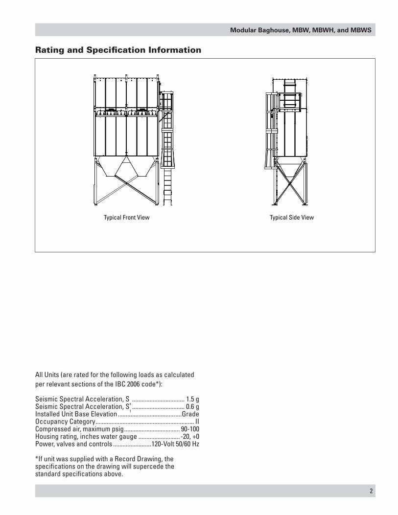
All Units (are rated for the following loads as calculated per relevant sections of the IBC 2006 code*):
Seismic Spectral Acceleration, Ss ................................. 1.5 g
Seismic Spectral Acceleration, S1 ................................. 0.6 g
Installed Unit Base Elevation ........................................GradeOccupancy Category .............................................................. IICompressed air, maximum psig ................................... 90-100Housing rating, inches water gauge .......................... -20, +0Power, valves and controls ........................120-Volt 50/60 Hz
*If unit was supplied with a Record Drawing, the specifications on the drawing will supercede the standard specifications above.
Modular Baghouse, MBW, MBWH, and MBWS
2
Rating and Specification Information
Typical Front View Typical Side View

3
Donaldson Company, Inc.
Operation
During normal operation, for a unit with hopper inlet(s), dust-laden air enters the unit through the hopper inlet located under the filter bags. Airflow is directed 90° upward to the dirty-air plenum. The energy loss from the 90° turn and reduced velocity in the hopper causes heavier particulate to fall directly into the hopper. An inlet baffle evenly distributes the dust-laden air around the filter bags.
During normal operation, for a high inlet unit, dust-laden air enters the high inlet section next to the filter bags. The airflow must turn 90° to pass through the filter bag section. The energy loss from turning and the reduced velocity in the inlet section causes the heavier dust particles to drop directly into the hopper below. Standard inlet baffles help to evenly distribute the dust-laden air around the filter bags.
Dust collects on the outside of each filter bag forming a dust-cake that increases filtering efficiency. Clean, filtered air passes through the filter bag to the clean-air plenum and discharges through the clean-air outlet.
The filter bags are pulse-cleaned automatically and sequentially, one row at a time. A timer energizes a solenoid valve causing the corresponding diaphragm valve to send a pulse of compressed air into the blowpipe. The high-pressure compressed air is forced through the center of the filter bags causing the collected dust to fall into the hopper where it is discharged into drums, a screw conveyor, or rotary valves.
dirty-air plenum
hopper
dirty-air inlet
walk-inclean-air plenum
back outlet, walk-in clean air plenum
service platform
filter accessdoor
ladder andcage
Unit Operation, 243MBW8 with Hopper Inlet

Modular Baghouse, MBW, MBWH, and MBWS
4
Unit Operation, 162MBWH8 with High Inlet
walk-inclean-air plenum
dirty-air plenum
dirty-air inlet
hopper
filter accessdoor
ladder
cage

5
Donaldson Company, Inc.
Inspection on Arrival
1. Inspect unit on delivery.
2. Report any damage to the delivery carrier.
3. Request a written inspection report from the Claims Inspector to substantiate claim.
4. File claims with the delivery carrier.
5. Compare unit received with description of product ordered.
6. Report incomplete shipments to the delivery carrier and your Donaldson Torit representative.
7. Remove crates and shipping straps. Remove loose components and accessory packages before lifting unit from truck.
8. Check for hardware that may have loosened during shipping.
9. Use caution removing temporary covers.
Installation Codes and Procedures
Codes may regulate recirculating filtered air in your facility.
Consult with the appropriate authorities having jurisdiction to ensure compliance with all national and local codes regarding recirculating filtered air.
Safe and efficient operation of the unit depends on proper installation.
Authorities with jurisdiction should be consulted before installing to verify local codes and installation procedures. In the absence of such codes, install unit according to the National Electric Code, NFPA No. 70-latest edition and NFPA 91 (NFPA 654 if combustible dust is present).
A qualified installation and service agent must complete installation and service of this equipment.
All shipping materials, including shipping covers, must be removed from the unit prior to, or during unit installation.
Failure to remove shipping materials from the unit will
compromise unit performance.
Inspect unit to ensure all hardware is properly installed and tight prior to operating collector.
Installation
Site selection must account for wind, seismic zone, and
other live-load conditions when selecting the location for all units.
Codes may regulate acceptable locations for installing dust collectors. Consult with the appropriate authorities having jurisdiction to ensure compliance with all national and local codes regarding dust collector installation.
Site Selection, Outdoor
Consider sound levels for adjacent properties and any noise regulations that may apply.
Locate the collector to ensure the shortest and straightest inlet- and outlet-duct length, easy access to electrical supply and compressed-air connections, solids collection containers, and routine maintenance.
Consider the effects of condensation caused by the temperature difference between the process airstream and outdoor temperatures.
Building codes or zoning requirements may restrict overall height, require screening, or regulate the distance from lot lines.
Prepare the foundation in the selected location and install anchor bolts as required by applicable local codes.
The foundation must be capable of supporting the entire weight of the unit, plus the weight of the collected material, piping, and ductwork.
When outdoor locations are selected, always mount motors with drain holes pointed down for proper drainage of moisture.
Consider explosion vent location and venting direction in accordance with NFPA.
Site Selection, Indoor
Locate the collector to ensure easy access to electrical and compressed-air connections, solid collection containers, and routine maintenance.
Consider forklift access for solid-collection container removal.
NOTICE
Modular Baghouse, MBW, MBWH, and MBWS
6
Locate the collector to minimize directional changes in ductwork. Avoid elbows immediately in front of the inlet.
Prepare the foundation in the selected location and install anchor bolts.
The foundation must be capable of supporting the entire weight of the unit, plus the weight of the collected material, piping, and ductwork.
Provide appropriate clearance from heat sources and avoid interference with utilities.
Consider explosion vent duct location (if applicable).
Unit Location
Donaldson Torit equipment is not designed to support
site-installed ducts, interconnecting piping, or electrical services. All ducts, piping, or electrical services supplied by others must be adequately supported to prevent severe personal injury and/or property damage.
When hazardous conditions or materials are present, consult with local authorities for the proper location of the collector.
Foundation or roof support must be sized to accommodate the entire weight of the unit, plus the weight of the collected material, piping, and ductwork.
Prepare the foundation in the selected location. Install anchor bolts to extend a minimum of 1 3/4-inches above foundation.
For hopper inlet units, locate the collector to ensure the shortest and straightest inlet- and outlet-duct length. Provide easy access to electrical and compressed-air connections for routine maintenance.
For high inlet units, locate the collector to ensure the inlet-duct is straight for at least five diameters in front of the collector. Outlet-ducts should be short and straight. Provide easy access to electrical and compressed-air connections for routine maintenance.
If explosion protection devices are part of the system, locate the collector in accordance with local code requirements (Example: NFPA 654). These codes may require units handling combustible dust be located either outside or against an outside wall.
Rigging Instructions
Suggested Tools & Equipment
Clevis Pins and Clamps Lifting SlingsCrane or Forklift Pipe SealantDrift Pins Pipe WrenchesDrill and Drill Bits ScrewdriversEnd Wrenches Socket WrenchesLarge Crescent Wrench Spreader Bars
Hoisting Information
Failure to lift the collector correctly can result in severe
personal injury or property damage.
Use appropriate lifting equipment and adopt all safety precautions needed for moving and handling the equipment.
A crane or forklift is recommended for unloading, assembly, and installation of the collector.
Location must be clear of all obstructions, such as utility lines or roof overhang.
Use all lifting points provided.
Use clevis connectors, not hooks, on lifting slings.
Use spreader bars to prevent damage to unit’s casing. Check the Specification Control drawing for weight and dimensions of the unit and components to ensure adequate crane capacity.
Allow only qualified crane operators to lift the equipment.
Refer to applicable OSHA regulations and local codes when using cranes, forklifts, and other lifting equipment. Lift unit and accessories separately, and assemble after unit is in place.
Use drift pins to align holes in section flanges during assembly.

7
Donaldson Company, Inc.
Electrical Wiring
Electrical service or maintenance work must be
performed by a qualified electrician and comply with all applicable national and local codes.
Turn power off and lock out electrical power sources before performing service or maintenance work.
Do not install in classified hazardous atmospheres without an enclosure rated for the application.
All electrical wiring and connections, including electrical grounding, should be made in accordance with the National Electric Code, NFPA No. 70-latest edition.
Check local ordinances for additional requirements that apply.
The appropriate wiring schematic and electrical rating must be used. See unit’s rating plate for required voltage.
If the unit is not furnished with a factory-mounted disconnect, an electric disconnect switch having adequate amp capacity shall be installed in accordance with Part IX, Article 430 of the National Electrical Code, NFPA No. 70-latest edition. Check unit’s rating plate for voltage and amperage ratings.
Refer to the wiring diagram for the number of wires required for main power wiring and remote wiring.
Correct Lifting Incorrect Lifting
lift lug
angle not to exceed 30° from vertical (min 60° from horizontal)
Lifting Point Orientation
Standard Equipment
Standard equipment consists of subassemblies, leg sets, pyramid or trough hoppers, filter housing, walk-in clean air plenum, ladder and cage, filter bags, filter cages, and blowpipes.
Field Assembly
Field assembly of subassemblies may be required due to truck capacity, crane capacity, or specific customer requirements. A detailed instruction drawing, shipped with each assembly, provides specific assembly and/or lifting instructions.
Hopper and Leg Assembly
1. Lift the hopper using a crane.
2. Stand each leg on its pad in position under hopper.
3. Use drift pins to align holes in the hopper gusset with holes in the legs.
4. Secure legs to hopper using bolts, washers, and nuts provided. Do not tighten hardware at this time. Do not remove crane.
5. Position and bolt the inside angles of the cross brace in place using the hardware provided. Do not tighten hardware at this time.
6. Position and bolt the outside angles of the cross brace in place using the hardware provided. Do not tighten hardware at this time.
7. Bolt inside and outside cross braces together where they form an X. Do not tighten hardware at this time.
8. Repeat steps six, seven, and eight for all brace locations. Do not tighten hardware at this time.
9. For complete leg assembly instructions, refer to instructions shipped with the leg pack.
10. Install anchor bolts to extend a minimum of 1 3/4-in above foundation.
Note: Tighten leg hardware and mark leg-pad holes on foundation. Lift the hopper and leg assembly and install HVA adhesive anchors as described on the Specification Control Drawing.
Modular Baghouse, MBW, MBWH, and MBWS
8
11. Lift the hopper and leg assembly and lower slowly to the anchor bolts.
12. Level the hopper at the top flange using steel shims if necessary. Secure leg pads to anchor bolts with the appropriate customer-supplied fasteners and nuts.
13. Tighten all hardware on the gussets, cross braces, and anchor bolts. Recheck level and adjust as necessary.
Tighten all hardware before removing crane to prevent
personal injury or property damage.
14. Remove crane.
Trough Hopper with Stub Legs
1. Trough hoppers have stub legs that can be attached to a structure supplied by others. The structure must be capable of supporting the entire weight of the unit, plus the weight of the collected material and auxiliary equipment. Wind, seismic, and other live loads must be considered.
2. Using a crane, lift hopper and position over the mounting structure. Align holes in stub legs with holes in the mounting structure and fasten securely.
Filter Housing to Hopper Assembly
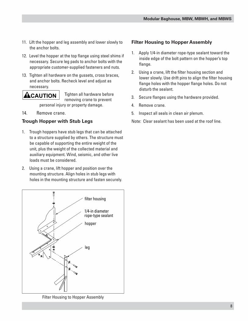
1. Apply 1/4-in diameter rope-type sealant toward the inside edge of the bolt pattern on the hopper’s top flange.
2. Using a crane, lift the filter housing section and lower slowly. Use drift pins to align the filter housing flange holes with the hopper flange holes. Do not disturb the sealant.
3. Secure flanges using the hardware provided.
4. Remove crane.
5. Inspect all seals in clean air plenum.
Note: Clear sealant has been used at the roof line.
Filter Housing to Hopper Assembly
filter housing
hopper
leg
1/4-in diameterrope-type sealant

9
Donaldson Company, Inc.
High Inlet Transition Installation
The inlet transition is an important component of the high inlet design. It is designed to ensure that airflow enters the collector at the proper velocity and flow distribution.
Proper inlet design is encouraged for the high inlet(s) to ensure
proper airflow distribution and velocity. A minimum of five diameters of straight duct is recommended prior to the inlet transition.
Fasten the high inlet transition to the high inlet flange on the collector using the fasteners, sealant, and instructions provided with the transition.
walk-inclean-air plenum
1/4-in diameterrope-typesealant
filter section
Clean-Air Plenum to Filter Housing Assembly
Walk-In Clean-Air Plenum
1. Apply 1/4-in diameter rope-type sealant toward the inside edge of the bolt pattern on the filter housing’s top flange.
2. Using a crane, lift the walk-in clean-air plenum into position over the filter housing.
3. Use drift pins to align the holes in the clean-air plenum flange with the holes in the filter housing flange being careful not to disturb the sealant.
4. Fasten securely using the hardware provided.
5. Inspect all seals in clean air plenum
Note: Clear sealant has been used at the roof line.
High Inlet Transition Installation
high inlettransition
1/4-in diameterrope-type sealant
NOTICE
Modular Baghouse, MBW, MBWH, and MBWS
10
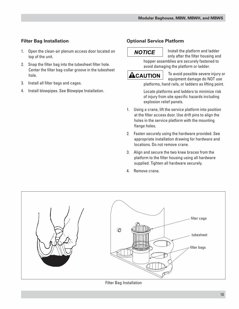
Filter Bag Installation
1. Open the clean-air plenum access door located on top of the unit.
2. Snap the filter bag into the tubesheet filter hole. Center the filter bag-collar groove in the tubesheet hole.
3. Install all filter bags and cages.
4. Install blowpipes. See Blowpipe Installation.
Filter Bag Installation
filter cage
tubesheet
filter bags
Optional Service Platform
Install the platform and ladder only after the filter housing and
hopper assemblies are securely fastened to avoid damaging the platform or ladder.
To avoid possible severe injury or equipment damage do NOT use
platforms, hand rails, or ladders as lifting point.
Locate platforms and ladders to minimize risk of injury from site specific hazards including explosion relief panels.
1. Using a crane, lift the service platform into position at the filter access door. Use drift pins to align the holes in the service platform with the mounting flange holes.
2. Fasten securely using the hardware provided. See appropriate installation drawing for hardware and locations. Do not remove crane.
3. Align and secure the two knee braces from the platform to the filter housing using all hardware supplied. Tighten all hardware securely.
4. Remove crane.
NOTICE
11
Donaldson Company, Inc.
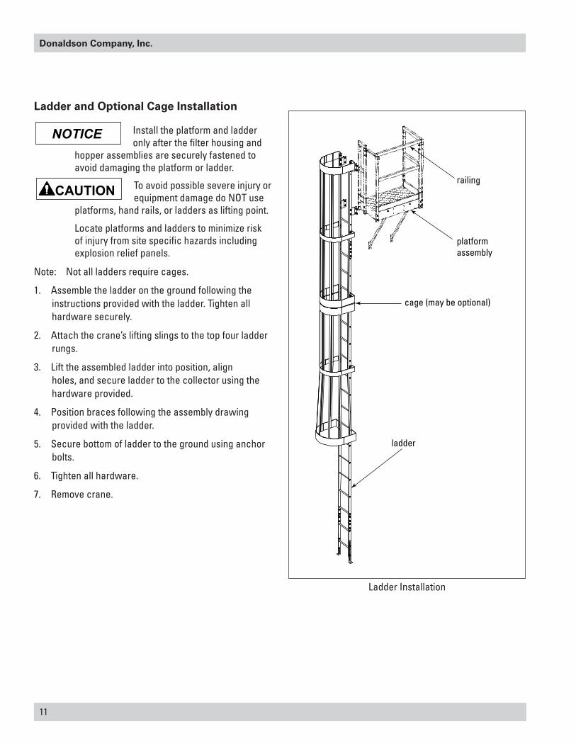
railing
cage (may be optional)
ladder
platformassembly
Ladder Installation
Ladder and Optional Cage Installation
Install the platform and ladder only after the filter housing and
hopper assemblies are securely fastened to avoid damaging the platform or ladder.
To avoid possible severe injury or equipment damage do NOT use
platforms, hand rails, or ladders as lifting point.
Locate platforms and ladders to minimize risk of injury from site specific hazards including explosion relief panels.
Note: Not all ladders require cages.
1. Assemble the ladder on the ground following the instructions provided with the ladder. Tighten all hardware securely.
2. Attach the crane’s lifting slings to the top four ladder rungs.
3. Lift the assembled ladder into position, align holes, and secure ladder to the collector using the hardware provided.
4. Position braces following the assembly drawing provided with the ladder.
5. Secure bottom of ladder to the ground using anchor bolts.
6. Tighten all hardware.
7. Remove crane.
NOTICE
Modular Baghouse, MBW, MBWH, and MBWS
12
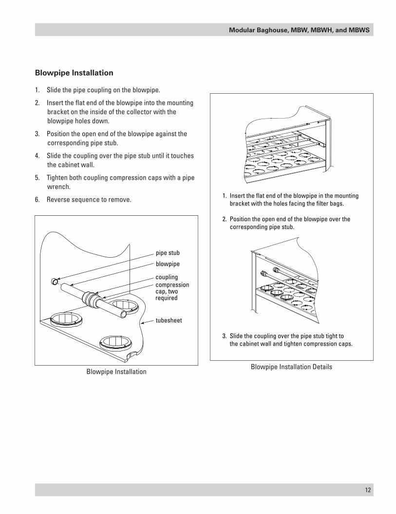
Blowpipe Installation
1. Slide the pipe coupling on the blowpipe.
2. Insert the flat end of the blowpipe into the mounting bracket on the inside of the collector with the blowpipe holes down.
3. Position the open end of the blowpipe against the corresponding pipe stub.
4. Slide the coupling over the pipe stub until it touches the cabinet wall.
5. Tighten both coupling compression caps with a pipe wrench.
6. Reverse sequence to remove.
pipe stub
tubesheet
blowpipe
couplingcompressioncap, tworequired
1. Insert the flat end of the blowpipe in the mounting bracket with the holes facing the filter bags.
2. Position the open end of the blowpipe over the corresponding pipe stub.
3. Slide the coupling over the pipe stub tight to the cabinet wall and tighten compression caps.
Blowpipe InstallationBlowpipe Installation Details
13
Donaldson Company, Inc.
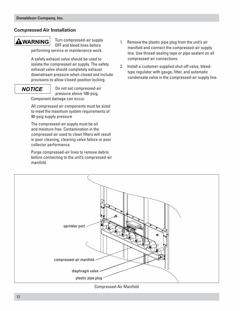
Compressed Air Installation
Turn compressed-air supply OFF and bleed lines before
performing service or maintenance work.
A safety exhaust valve should be used to isolate the compressed air supply. The safety exhaust valve should completely exhaust downstream pressure when closed and include provisions to allow closed-position locking.
Do not set compressed-air pressure above 100-psig.
Component damage can occur.
All compressed air components must be sized to meet the maximum system requirements of 90-psig supply pressure
The compressed-air supply must be oil and moisture free. Contamination in the compressed air used to clean filters will result in poor cleaning, cleaning valve failure or poor collector performance.
Purge compressed-air lines to remove debris before connecting to the unit’s compressed-air manifold.
1. Remove the plastic pipe plug from the unit’s air manifold and connect the compressed-air supply line. Use thread-sealing tape or pipe sealant on all compressed-air connections.
2. Install a customer-supplied shut-off valve, bleed-type regulator with gauge, filter, and automatic condensate valve in the compressed-air supply line.
sprinkler port
compressed-air manifold
diaphragm valve
plastic pipe plug
Compressed-Air Manifold
NOTICE

Modular Baghouse, MBW, MBWH, and MBWS
14
Compressed Air and Component Connections (81MBW8 shown)
clean-air outlet, back of walk-in plenum
clean-air outlet, back
walk-in plenumplenum access door
filter housing
hopper
legs
ladder and cage assembly
solenoid electrical connection*air supply to manifold*
air regulator*bleed-type air filter*
compressed-air shut-off valve*
Magnehelic or Photohelic gauge
solid-state timer
power supply disconnect switch*
dirty-air hopper inlet
sprinkler ports for optional sprinkler heads
compressed-air supply*
Note: *Not included with standard unit
Turn compressed-air supply OFF and bleed lines before performing service or maintenance work.

15
Donaldson Company, Inc.
Solid-State Timer Installation
Electrical service or maintenance work must be
performed by a qualified electrician and comply with all applicable national and local codes.
Turn power off and lock out electrical power sources before performing installation, service, or maintenance work.
Do not install in classified hazardous atmospheres without an enclosure rated for the application.
The solid-state timer is an electronic timer used to control the filter cleaning system. Available options include 10, 20, or 32-pin solenoid valve control.
1. Using the wiring diagram supplied, wire the blower motor, blower-motor starter, solid-state timer, and solenoid valves. Use appropriate wire gauge for rated amp load as specified by local codes.
2. Plug the program lug into the pin that corresponds with the number of solenoid valves controlled.
3. With power supply ON, check the operation of the solenoid valves. The valves should open and close sequentially at factory set 10-second intervals.
4. If a Photohelic gauge or similar device is used to control the solid-state timer and the jumper on the pressure switch portion of the timer is removed, the solenoid valves pulse only when the differential pressure reaches the high-pressure setpoint. The valves continue to pulse until the low-pressure setpoint is reached.
The solid-state timer voltage must match the voltage of the
rating of the timer provided (typically 115VAC).
Do not mount the solid-state timer on the unit. Mechanical vibration can damage the control.
Solenoid Connection
The unit is equipped with solenoid valves (typically 115V) that control the pulse-cleaning valves, which clean the filter bags.
One of three types of solenoid enclosures, the weatherproof NEMA 4 with 3D2 solenoids, the explosion proof NEMA 7 with 5D2 solenoids, or the explosion proof NEMA 9 with 5D2 solenoids, is mounted near or on the unit’s compressed-air manifold.
Wire the solenoids to the solid-state timer following the wiring diagram supplied with the unit. Filter life and cleaning operation will be affected if not wired correctly.
Timer and Solenoid Specifications
Power to the solid-state timer is supplied to Terminals L1 and L2, which operate in parallel with the blower starter’s low-voltage coil. On blower start-up, power is supplied to the timer and the preset OFF time is initiated. At the end of the OFF time, the timer energizes the corresponding solenoid valve to provide the ON time cleaning pulse for one diaphragm valve and then steps to the next until all filter bags have been cleaned.
To pulse when the blower is OFF, install a toggle switch as shown on the Solid-State Timer Wiring Diagram. When the toggle switch is ON, the timer receives power and energizes the solenoid valves’ pulse-cleaning operation even though the blower is turned OFF.
NOTICE

Modular Baghouse, MBW, MBWH, and MBWS
16
Input 105-135V/50-60Hz/1Ph
Output Solenoids The load is carried and turned ON and OFF by the 200 watt maximum-load-per-output solid-state switch.
Pulse ON Time Factory set at 100-milliseconds, or 1/10-second.
Do not adjust pulse ON time unless the proper test equipment
is available. Too much or too little ON time can cause shortened filter life.
Pulse OFF Time Factory set at 10-seconds, adjustable from 1.5-sec minimum to maximum 30-seconds.
Operating Temperature Range -20° F to 130° F
Transient Voltage Protection 50 kW transient volts for 20-millisecond duration once every 20 seconds, 1% duty cycle.
Solenoid Valves 115-V at 19.7 watts each
Compressed-Air Set compressed-air supply at 90-psig. The timer is factory set to clean one filter bag or set of filter bags every 10-seconds.
Do not increase supply pressure above 100-psig. Component
damage will occur.
NOTICE
Fan Starter Control BoxDisconnect
1FU
2FU
3FU
208-230V60 Hz/3Ph
IL1
IL2
IL3
1M 1OL 1T1
1T2
1T3
230V
115V
H1 H2H3 H4
X1 X2
stop
start
1M
1M
1TGS
fanmotor
OFF time ON time
programpins program lug
pressureswitch
timinglogic
powersupply
controllogic
4FU, 3A
105 to 135 V50-60 Hz
solenoidvalves
COM
L1
L2
L3
Disconnect, fuses, low voltage blower starter, and 1TGS switch are customer-supplied.
Use wiring diagram provided with unit
Wiring by othersWiring by factory
L1 L2 21
Verify if this it the right illustration to use or should it be the one without ground?
Solid-State Timer Typical Wiring Diagram
NOTICE
17
Donaldson Company, Inc.
Preliminary Start-Up Check
Instruct all personnel on safe use and maintenance procedures.
Electrical work during installation must be performed by a qualified
electrician and comply with all applicable national and local codes.
Turn power off and lock out electrical power sources before performing service or maintenance work.
Turn compressed air supply OFF and bleed lines before performing service or maintenance work
Check that the collector is clear and free of all debris before starting.
Do not install in classified hazardous atmospheres without an enclosure rated for the application.
Optional fans over 600 lbs must be independently supported.
1. Check all electrical connections for tightness and contact.
2. Motor and fan should be wired for clockwise rotation when viewed from the back of the motor.
To reverse rotation, single-phase power supply: Follow manufacturer’s instructions on the motor’s nameplate.
To reverse rotation, three-phase power supply: Turn electrical power OFF at source and switch any two leads on the motor junction box.
Do not interchange a power lead with the ground wire. Severe
personal injury or equipment damage may result.
3. All access panels should be sealed and secure.
4. Check that the dust container is properly sealed and clamped.
5. Check that exhaust damper is set to the fully-closed position.
6. Check and remove all loose items in or near the inlet and outlet of the unit.
7. Check that all remote controls and solenoid enclosures (if applicable) are properly wired and all service switches are in the OFF position.
8. Check that all optional accessories are installed properly and secured.
9. Turn power ON at source.
10. Turn the compressed-air supply ON. Adjust pressure regulator for 90-100 psig.
11. Turn blower fan motor ON.
Do not look into fan outlet to determine rotation. View the fan
rotation through the back of the motor.
Check that the exhaust plenum is free of tools or debris before checking blower/fan rotation.
Stand clear of exhaust to avoid personal injury.
12. Adjust airflow with the exhaust damper.
Excess airflow can shorten filter bag life, cause electrical system
failure, and blower motor failure.
NOTICE

Modular Baghouse, MBW, MBWH, and MBWS
18
Maintenance Information
Instruct all personnel on safe use and maintenance procedures.
Use proper equipment and adopt all safety precautions needed
for servicing equipment. Electrical service or maintenance work must be performed by a qualified electrician and comply with all applicable national and local codes.
Turn power off and lock out electrical power sources before performing service or maintenance work.
Do not install in classified hazardous atmospheres without an enclosure rated for the application.
Turn compressed air supply OFF and bleed lines before performing service or maintenance work.
Do not set compressed-air pressure above 100-psig.
Component damage can result.
All compressed air components must be sized to meet the maximum system requirements of 90-100 psig.
The compressed-air supply must be oil and moisture free. Contamination in the compressed air used to clean filters will result in poor cleaning, cleaning valve failure, or poor collector performance.
Purge compressed air lines to remove debris before connecting to the unit’s compressed air manifold.
Operational Checklist
1. Monitor the physical condition of the collector and repair or replace any damaged components.
Routine inspections will minimize downtime and maintain optimum system performance. This is particularly important on continuous-duty applications.
Periodically check the compressed air components and replace compressed air filters. Drain moisture following the manufacturer’s instructions. With the compressed air supply ON, check the cleaning valves, solenoid valves, and tubing for leaks. Replace as necessary.
2. Monitor pressure drop across filters.
Abnormal changes in pressure drop indicate a change in operating conditions and possibly a fault to be corrected. For example, prolonged lack of compressed air will cause an excess build-up of dust on the filters resulting in increased pressure drop. Cleaning off-line with no flow usually restores the filters to normal pressure drop.
3. Monitor exhaust.
4. Monitor dust disposal.
Filter Removal and Installation
Use proper safety and protective equipment when removing
contaminants and filters.
Dirty filters may be heavier than they appear.
Use care when removing filters to avoid personal injury.
Filter Removal
1. Turn power to unit OFF.
2. Shut off and bleed compressed air-supply.
3. Open the access door and remove blowpipes. See Blowpipe Installation.
4. Lift the quick-release cage handle and pull the filter cage from the bag and set aside.
5. Grasp the filter bag collar firmly on the seamed side and pull away from the tubesheet.
6. Push the filter bag down through the tubesheet carefully.
7. Remove filter bags from hopper and dispose of properly.
NOTICE

19
Donaldson Company, Inc.
Filter Replacement
1. Snap the filter bag into the tubesheet filter hole. Center the filter bag-collar groove in the tubesheet hole.
2. Install all filter bags and cages.
3. Install blowpipes. See Blowpipe Installation.
Filter Bag Installation
filter cage
tubesheet
filter bags
Modular Baghouse, MBW, MBWH, and MBWS
20
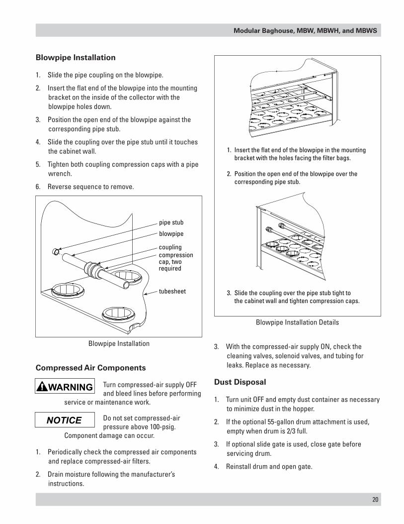
Blowpipe Installation
1. Slide the pipe coupling on the blowpipe.
2. Insert the flat end of the blowpipe into the mounting bracket on the inside of the collector with the blowpipe holes down.
3. Position the open end of the blowpipe against the corresponding pipe stub.
4. Slide the coupling over the pipe stub until it touches the cabinet wall.
5. Tighten both coupling compression caps with a pipe wrench.
6. Reverse sequence to remove.
pipe stub
tubesheet
blowpipe
couplingcompressioncap, tworequired
1. Insert the flat end of the blowpipe in the mounting bracket with the holes facing the filter bags.
2. Position the open end of the blowpipe over the corresponding pipe stub.
3. Slide the coupling over the pipe stub tight to the cabinet wall and tighten compression caps.
Blowpipe Installation
Blowpipe Installation Details
NOTICE
Compressed Air Components
Turn compressed-air supply OFF and bleed lines before performing
service or maintenance work.
Do not set compressed-air pressure above 100-psig.
Component damage can occur.
1. Periodically check the compressed air components and replace compressed-air filters.
2. Drain moisture following the manufacturer’s instructions.
3. With the compressed-air supply ON, check the cleaning valves, solenoid valves, and tubing for leaks. Replace as necessary.
Dust Disposal
1. Turn unit OFF and empty dust container as necessary to minimize dust in the hopper.
2. If the optional 55-gallon drum attachment is used, empty when drum is 2/3 full.
3. If optional slide gate is used, close gate before servicing drum.
4. Reinstall drum and open gate.

21
Donaldson Company, Inc.
Optional Equipment
Power Pack
The two types of power packs, Torit Backward Inclined (TBI) and Torit Radial Blade (TRB) are installed following the same procedure.
1. Power packs are shipped assembled and partial disassembly is required before installing.
2. Remove eight motor-mount bracket fasteners; remove the motor, motor-mount bracket, and fan wheel as an assembly.
3. Turn housing over and apply sealant to the outside edge of the bolt pattern on the fan housing. Mount the fan housing to the collector using the inlet cone fasteners.
4. Apply sealant to the outside edge of the bolt pattern on the fan housing. Reinstall the motor, bracket, and fan wheel asembly. Align motor mount bracket to the mark on the housing on 30 Hp, 60 Hz, and 20-30 Hp, 50 Hz units. Other motor sizes do not require alignment, but consider the electrical connection location.
5. Rotate fan wheel after installation to ensure proper clearance between the inlet cone and the fan wheel.
Do not look into fan outlet to determine rotation. View the fan
rotation from the back of the motor.
Check that the exhaust plenum is free of tools or debris before checking blower/fan rotation.
Stand clear of exhaust to avoid personal injury.
To reverse rotation, three-phase power supply: Turn electrical power OFF at source and switch any two leads on the motor junction box.
Do not interchange a power lead with the ground wire. Severe
personal injury or equipment damage may result.
Wheel Setscrew Torque
Setscrew Size Diameter
Carbon Steel Setscrew Torque*
In. Lb. - In. Lb. - Ft.1/4 75 6.25/16 144 123/8 252 217/16 396 331/2 600 505/8 1164 973/4 2016 1687/8 3204 2671 4800 400*Stainless steel setscrews are not hardened and should not be tightened to more than half of the values shown.
Do not allow the fan wheel to come loose from the motor as it
may cause severe injury or property damage. To ensure proper attachment of the fan wheel:
Tighten all setscrews in fan wheel.*
Tighten all setscrews in bearings.*
Repeat after 8 hours of operation.
Repeat again after two weeks of operation.
Reference Wheel Setscrew Torque Table.

Modular Baghouse, MBW, MBWH, and MBWS
22
Side Mount Power Pack Adaptor
Electrical service or maintenance work must be
performed by a qualified electrician and comply with all applicable national and local codes.
Turn power off and lock out electrical power sources before performing service or maintenance work.
Do not install in classified hazardous atmospheres without an enclosure rated for the application.
Mounting a power pack on the side of a collector requires a side
power adapter to support the weight of the power pack.
Poorly installed power packs may separate from the collector resulting in personal injury and damage to equipment or property.
The side mount power pack adaptor is available for the 81MBW8, 10, 108MBW8, 10, 162MBW8 and the high inlet models 54MBWH8, 10, and 81MBWH8. The power pack adaptor allows a TBI3-30 HP blower to be mounted directly to the modular baghouse outlet on the rear of the collector housing. It is not designed to be mounted on the outlet of the walk-in plenum. Field assembly of the side mount power pack adaptor is required. This allows the adaptor to be assembled to the outlet location of the customer's choosing.
1. Remove the collector outlet cover.
2. Fasten the adaptor to the collector outlet using the hardware and sealant provided.
3. Mount the blower to the adaptor following the instructions supplied with the blower power pack.
55-Gallon Drum Pack
The drum pack is designed to fit a customer-supplied, standard 55-gallon drum and provides easy access for dust removal and disposal. A flexible hose connects the drum cover and slide gate, or drum cover and adapter. Placing a pallet under the drum allows heavier product to be moved quickly using a forklift or pallet jack. If a pallet is used, the length of flexible hose may need to be shortened.
adaptor
rope type sealant
Side Mount Power Pack Adaptor
With Slide Gate
1. Place the 1/8-in gasket spacer between the hopper flange and slide gate as shown.
2. Attach the drum pack and slide gate to the hopper flange using 3/8-16 bolts, washers, and hex nuts.
3. Attach the drum cover to the 55-gallon drum.
4. Use latches to secure the cover to the drum, if equipped.
5. Connect the flexible hose between the drum cover and slide gate. Secure with hose clamps.
Without Slide Gate
1. Place the 1/4-in diameter rope-type sealant between the hopper flange and the adapter as shown.
2. Attach the adapter to the hopper flange using 3/8-16 bolts, washers, and hex nuts.
3. Attach the drum cover to the 55-gallon drum.
4. Use latches to secure the cover to the drum, if equipped.
5. Connect the flexible hose between the drum cover and the adapter. Secure with hose clamps.

23
Donaldson Company, Inc.
hopper flange
drum cover
slide gate
optional latch
customer-supplied55-gallon drumhose clamp
flexible hose
1/8-in gasket spacer
3/8-16 bolt
3/8-in flat washer
3/8-in lock washer3/8-16 hex nut
hopper flange
drum cover
optional latch
customer-supplied55-gallon drum
hose clampflexible hose
1/4-in diameterrope-type sealant
3/8-16 bolt
3/8-in flat washer
3/8-in lock washer
3/8-16 hex nut
adapter
55-Gallon Drum Pack with Slide Gate
55-Gallon Drum Pack without Slide Gate

Modular Baghouse, MBW, MBWH, and MBWS
24
Magnehelic® Gauge
The Magnehelic is a differential pressure gauge used to measure the pressure difference between the clean- and dirty-air plenums and provides a visual display of filter change requirements. The high-pressure tap is located in the dirty-air plenum and the low-pressure tap is located in the clean-air plenum.
1. Choose a convenient, accessible location on or near the unit for mounting that provides the best visual advantage.
If unit is equipped with factory-installed pressure taps, skip to Step 5.
2. Before drilling, place a piece of non-combustible cloth over the filter opening in the clean-air plenum to protect them from drilling chips.
3. Place a piece of wood behind the drill location in the dirty-air plenum to protect the filters from damage by the drill bit.
4. Mount the pressure tap hardware on the clean-air plenum panel and the dirty-air plenum.)
5. Plug the pressure ports on the back of the gauge using two, 1/8-in NPT pipe plugs supplied. Install two, 1/8-in NPT male adapters supplied with the gauge into the high- and low-pressure ports on the side of the gauge.
6. Attach the mounting bracket using three, #6-32 x 1/4-in screws supplied.
7. Mount the gauge and bracket assembly to the supporting structure using two, self-drilling screws.
8. Thirty-five feet of plastic tubing is supplied and must be cut in two sections. Connect one section of tubing from the gauge’s high-pressure port to the pressure fitting located in the dirty-air plenum. Connect remaining tubing from the gauge’s low-pressure port to the fitting in the clean-air plenum. Additional tubing can be ordered from your representative.
9. Carefully remove the cloth protecting the filters. Close access doors and tighten securely by hand.
10. Zero and maintain the gauge as directed in the manufacturer’s Operating and Maintenance Instructions provided.
1/8-in NPT x 90°male elbowclean-air plenum pressure
tap location 1/8-in NPT adapter
1/8-in NPT adapter
plenum tap location 3/8-in flat washer
1/8-in NPT coupling
mounting bracket
#6-32 x 1/4-in mounting screws
support structuremounting surface
Magnehelic gauge
high-pressure portlow-pressure port
two, 1/8-in NPTadapters
plastic tubing
two, 1/8-in NPT pipe plugs
two, self-drilling screws
1/8-in NPT x 90° male elbow
dirty-air plenum pressure tap location3/8-in flat washer
1/8-in NPT adapter1/8-in NPT x 90° elbow
static pressure tee
Magnehlic Gauge Installation
25
Donaldson Company, Inc.
Photohelic® Gauge
Electrical service or maintenance work must be
performed by a qualified electrician and comply with all applicable national and local codes.
Turn power off and lock out electrical power sources before performing service or maintenance work.
Do not install in classified hazardous atmospheres without an enclosure rated for the application.
The Photohelic combines the functions of a differential pressure gauge and a pressure-based switch. The gauge function measures the pressure difference between the clean- and dirty-air plenums and provides a visual display of filter condition. The high-pressure tap is located in the dirty-air plenum and a low-pressure tap is located in the clean-air plenum. The pressure-based switch function provides high-pressure ON and low-pressure OFF control of the filter cleaning system.
1. Choose a convenient, accessible location near the unit that provides the best visual advantage.
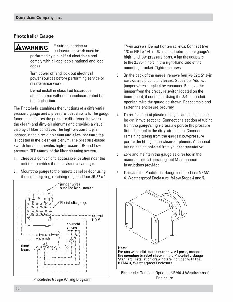
2. Mount the gauge to the remote panel or door using the mounting ring, retaining ring, and four #6-32 x 1
1/4-in screws. Do not tighten screws. Connect two 1/8-in NPT x 1/4-in OD male adapters to the gauge’s high- and low-pressure ports. Align the adapters to the 2.375-in hole in the right-hand side of the mounting bracket. Tighten screws.
3. On the back of the gauge, remove four #6-32 x 5/16-in screws and plastic enclosure. Set aside. Add two jumper wires supplied by customer. Remove the jumper from the pressure switch located on the timer board, if equipped. Using the 3/4-in conduit opening, wire the gauge as shown. Reassemble and fasten the enclosure securely.
4. Thirty-five feet of plastic tubing is supplied and must be cut in two sections. Connect one section of tubing from the gauge’s high-pressure port to the pressure fitting located in the dirty-air plenum. Connect remaining tubing from the gauge’s low-pressure port to the fitting in the clean-air plenum. Additional tubing can be ordered from your representative.
5. Zero and maintain the gauge as directed in the manufacturer’s Operating and Maintenance Instructions provided.
6. To install the Photohelic Gauge mounted in a NEMA 4, Weatherproof Enclosure, follow Steps 4 and 5.
Photohelic gauge
solenoidvalves
Pressure Switchterminals
neutral110-V
jumper wiressupplied by customer
timerboard L1 L2 1 2 3
solcom
L2 L1
HI LO
C NO NC NC NO C
C NO NC NC NO C
Photohelic Gauge Wiring Diagram
Note:For use with solid-state timer only. All parts, except the mounting bracket shown in the Photohelic GaugeStandard Installation drawing are included with the NEMA 4, Weatherproof Enclosure.
Photohelic Gauge in Optional NEMA 4 Weatherproof Enclosure

Modular Baghouse, MBW, MBWH, and MBWS
26
clean air plenumpressure tap location
1/8-in NPT maleadapter
NPT male adapter
static pressure tee
dirty air plenum pressure tap location
1/8-in NPT male adapter
plastic tubing
two 1/8-in NPT adapters
low-pressure port
high-pressure portPhotohelic gauge
Photohelic Gauge, Remote Panel or Door Installation
27
Donaldson Company, Inc.
Delta P Control
Description
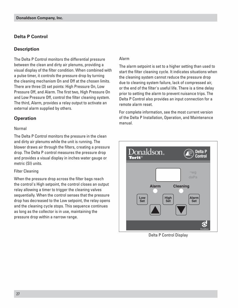
The Delta P Control monitors the differential pressure between the clean and dirty air plenums, providing a visual display of the filter condition. When combined with a pulse timer, it controls the pressure drop by turning the cleaning mechanism On and Off at the chosen limits. There are three (3) set points: High Pressure On, Low Pressure Off, and Alarm. The first two, High Pressure On and Low Pressure Off, control the filter cleaning system. The third, Alarm, provides a relay output to activate an external alarm supplied by others.
Operation
Normal
The Delta P Control monitors the pressure in the clean and dirty air plenums while the unit is running. The blower draws air through the filters, creating a pressure drop. The Delta P control measures the pressure drop and provides a visual display in inches water gauge or metric (SI) units.
Filter Cleaning
When the pressure drop across the filter bags reach the control's High setpoint, the control closes an output relay allowing a timer to trigger the cleaning valves sequentially. When the control senses that the pressure drop has decreased to the Low setpoint, the relay opens and the cleaning cycle stops. This sequence continues as long as the collector is in use, maintaining the pressure drop within a narrow range.
Alarm
The alarm setpoint is set to a higher setting than used to start the filter cleaning cycle. It indicates situations when the cleaning system cannot reduce the pressure drop due to cleaning system failure, lack of compressed air, or the end of the filter's useful life. There is a time delay prior to setting the alarm to prevent nuisance trips. The Delta P Control also provides an input connection for a remote alarm reset.
For complete information, see the most current version of the Delta P Installation, Operation, and Maintenance manual.
Delta P Control Display

Modular Baghouse, MBW, MBWH, and MBWS
28
Delta P Plus Control
The Delta P Plus Control monitors the differential pressure between the clean and dirty air plenums, providing a visual display of the filter condition. When combined with a pulse timer, it controls the pressure drop by turning the cleaning mechanism On and Off at the chosen limits. There are three (3) set points: High Pressure Drop On, Low Pressure Drop Off, and Alarm. The first two, High Pressure Drop On and Low Pressure Drop Off, control the filter cleaning system. The third, Alarm, provides a relay output to activate an external alarm supplied by others.
The user can program the Delta P Plus Control to pulse while the collector is running, to maintain a relatively constant pressure drop across the filters, pulse only after the collector is shut down (after-shift cleaning), or a combination of both, cleaning while running as well as end of the shift.
Operation
Normal
The Delta P Plus Control monitors the pressure on both sides of the tubesheet while the unit is running. The blower draws air through the filters, creating a pressure drop. The Delta P Plus Control measures the pressure drop and provides a visual display in inches water gauge or metric (SI) units.
Filter Cleaning
The Delta P Plus Control offers three filter cleaning options.
1. Differential Pressure Cleaning (DFF) - When the pressure drop across the filters reaches the control's High setpoint, the control closes an output relay allowing a sequential timer to trigger the cleaning valves. When the control senses that the pressure drop has decreased to the Low setpoint, the relay opens and the cleaning cycle stops. This sequence continues as long as the collector is in use, maintaining the pressure drop within a narrow range.
2. Down Time Cleaning (DTC) - The Delta P Plus Control monitors the collection system. It watches for the
blower to start, the pressure drop to exceed the Low setpoint, and then for the pressure drop to approach zero. After the blower has come to a stop, the Delta P Plus engages the cleaning mechanism for a pre-selected time.
3. Combined Differential and Down Time Cleaning (ALL) - The Delta P Plus Control combines the two functions described above; maintaining the pressure drop in a narrow band and down time cleaning the filters when the collector is shut down. The down time cleaning function can be toggled On or Off from the keyboard.
Alarm
The alarm setpoint is set to a higher setting than used to start the filter cleaning cycle. It indicates situations when the cleaning system cannot reduce the pressure drop due to cleaning system failure, lack of compressed air, or the end of the filter's useful life. There is a time delay prior to setting the alarm to prevent nuisance trips. The Delta P Plus Control also provides an input connection for a remote alarm reset.
For complete information, see the most current version of the Delta P Plus Installation, Operation, and Maintenance manual.
Delta P Plus Control Display

29
Donaldson Company, Inc.
Transition and Rotary Valve
Rotating blades can cause serious injury.
Turn power off and lock out electrical source before performing service or maintenance work.
Keep hands, feet and loose clothing away from both inlet and outlet openings to avoid injury or damage when valve is operating.
Transitions are not intended or capable of supporting the weight
of the airlock. Provide adequate support to prevent personal injury and damage to airlock or collector.
The 7-inch tall transition is designed to connect a standard hopper and a rotary valve which is used as an airlock in dust control applications. The airlock provides an air seal between the valve’s inlet and outlet while allowing dust or material to pass through. Comparatively, the airlock works along the same line as a revolving door on a building —an air seal is maintained while people are allowed to pass through.
The valve allows a specific amount of material to pass per revolution, depending on the size and speed of the valve. Standard sizes include 8, 10, 12, and 16-in inlets.
1. Place 1/4-in diameter rope-type sealant to the inside of the transition’s bolt pattern.
2. Use 3/8-16 bolts, washers, and hex nuts to fasten transition to hopper.
3. Determine the proper position required for the rotary airlock. Allow clearance for electrical connections and future maintenance.
4. Place 1/4-in diameter rope-type sealant toward the inside-edge of the airlock’s top flange.
5. Fasten the airlock to the transition flange using 3/8-16 bolts, washers, and hex nuts.
6. Electrical connections must be made by a qualified electrician. Refer to the motor’s nameplate for voltage, amp rating, cycle, and wiring sequence.
3/8-16
3/8-in flat washer
1/4-in diameterrope-type sealantplaced inside bolt pattern
3/8-in flat washer
3/8-16 hex
hopper flange
8, 10, 12, or 16-intransition
3/8-16 hex nut
3/8-in flat washer
3/8-16 bolt
3/8-in flat washer
8, 10, 12, or 16-inrotary airlock
1/4-in diameterrope-type sealantplaced inside bolt pattern
Transition and Rotary Valve
Modular Baghouse, MBW, MBWH, and MBWS
30
Cold Climate Kit
Electrical service or maintenance work during
installation must be performed by a qualified electrician and comply with all applicable national and local codes.
Turn power off and lock out electrical power sources before performing service or maintenance work.
A cold climate kit provides heat to the pulse valves to prevent cold weather freeze up. The basic kit, for use in applications that have a moderate amount of moisture in the compressed-air supply, consists of a small heating element and thermostat installed in the solenoid enclosure. The basic kit is factory-installed and supplied with the appropriate solenoid wiring instructions.
A heavy-duty kit is available for applications that have moderate-to-high amounts of moisture in the compressed-air supply and consists of the basic kit plus a heat cable to deliver heat to the large pulse valves. This kit is customer-installed and detailed installation instructions are provided.
1. Install the power connection kit on the heat cable following the manufacturer’s instructions.
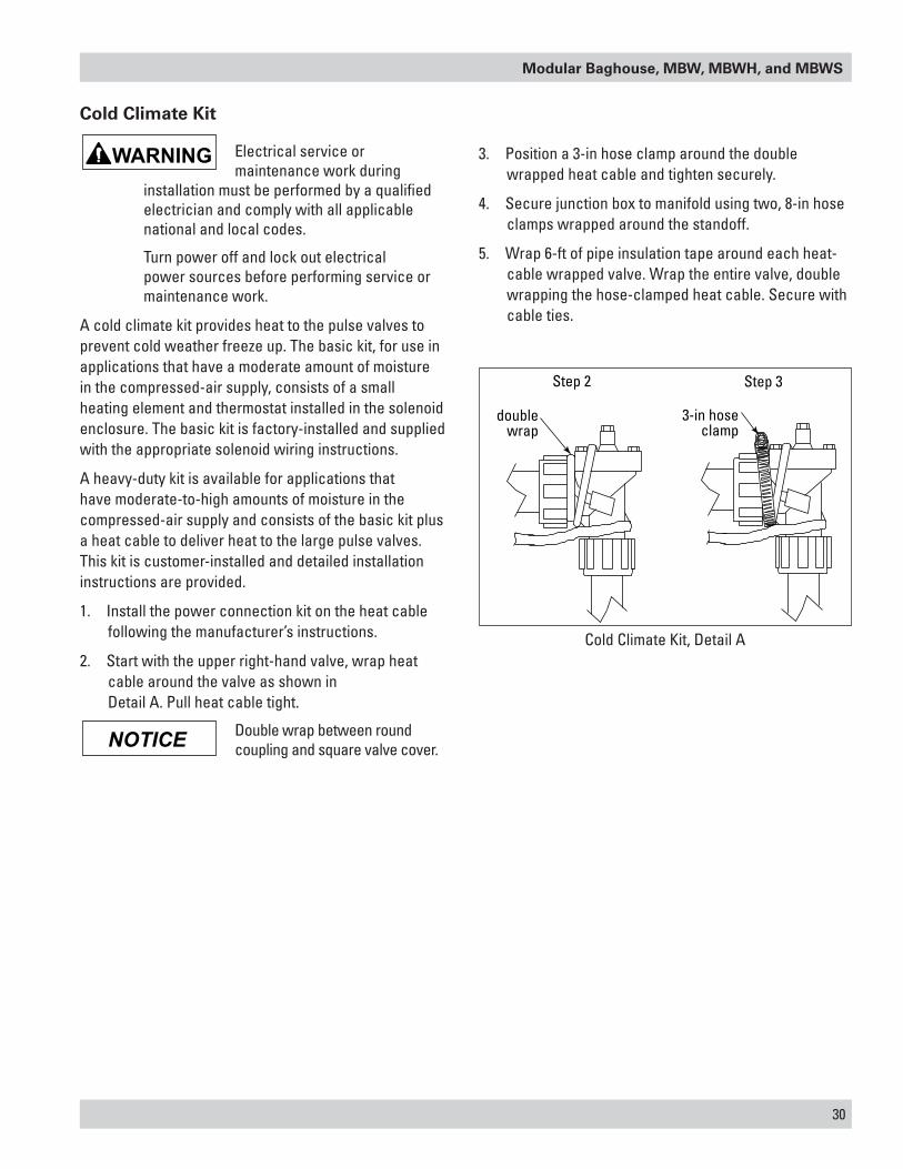
2. Start with the upper right-hand valve, wrap heat cable around the valve as shown in Detail A. Pull heat cable tight.
Double wrap between round coupling and square valve cover.
3. Position a 3-in hose clamp around the double wrapped heat cable and tighten securely.
4. Secure junction box to manifold using two, 8-in hose clamps wrapped around the standoff.
5. Wrap 6-ft of pipe insulation tape around each heat-cable wrapped valve. Wrap the entire valve, double wrapping the hose-clamped heat cable. Secure with cable ties.
NOTICE
doublewrap
3-in hoseclamp
Step 2 Step 3
Cold Climate Kit, Detail A

31
Donaldson Company, Inc.
Explosion Relief Vents
Personal injury, death, or property damage can result from
material discharge during venting.
The material discharged during the venting of an explosion must be safely directed outdoors away from areas occupied by personnel to reduce risk of personal injury or property damage.
The risk of injury or damage can be minimized or avoided by locating vented equipment outside buildings and away from normally occupied areas.
Explosion vents should be inspected regularly to confirm physical and operational condition. Replace any damaged parts immediately.
Standard explosion vents are intended for outdoor installations only.
Remove all shipping materials, including covers, from the
explosion relief vents prior to installation. Failure to remove shipping covers will seriously compromise explosion vent operation.
Explosion venting calculations are based on formulas from NFPA-68 for outdoor applications only, with no duct or obstructions on the explosion vent panel.
Contact Donaldson for assistance in calculating specific venting requirements for equipment.
Sprinkler Installation
Sprinkler systems place a large quantity of water in the dust
collector when activated. Provide adequate drainage to remove water. Excess water weight can cause the leg structure to collapse.
Fire control sprinklers are available for all models operating under negative pressure. Donaldson Torit supplied sprinklers require a minimum of 15-psig water pressure. The volume of water discharged per sprinkler head is 17 gallons per minute.
Consult with local authorities when installing fire control
systems on dust collection equipment.
1. Remove or open the filter access doors to access the sprinkler taps located in the clean-air plenum.
2. Apply pipe sealant to the threads of the pipe reducer located on the sprinkler assembly.
3. Thread sprinkler assembly onto the 1-in diameter sprinkler tap.
4. Tighten securely.
5. Install flood valves on the hopper access openings to relieve water build up in the hoppers.
NOTICE
NOTICE
access from inside the dirty-air plenum
Sprinkler Installation
Modular Baghouse, MBW, MBWH, and MBWS
32
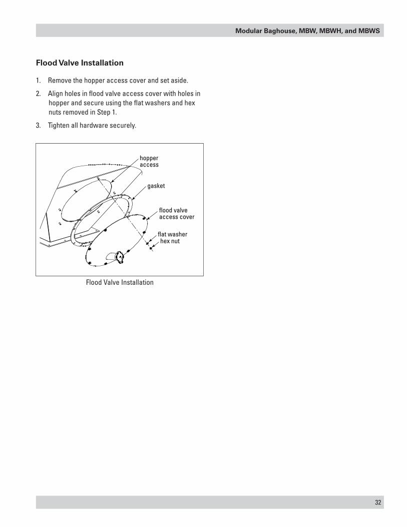
Flood Valve Installation
1. Remove the hopper access cover and set aside.
2. Align holes in flood valve access cover with holes in hopper and secure using the flat washers and hex nuts removed in Step 1.
3. Tighten all hardware securely.
Flood Valve Installation
hopperaccess
gasket
flood valveaccess cover
flat washerhex nut

33
Donaldson Company, Inc.
Troubleshooting
Problem Probable Cause Remedy
Blower fan and motor do not start
Improper motor wire size Rewire using the correct wire gauge as specified by national and local codes.
Not wired correctly Check and correct motor wiring for supply voltage. See motor manufacturer's wiring diagram. Follow wiring diagram and the National Electric Code.
Unit not wired for available voltage
Correct wiring for proper supply voltage.
Input circuit down Check power supply to motor circuit on all leads.Electrical supply circuit down Check power supply circuit for proper voltage.
Check for fuse or circuit breaker fault. Replace as necessary.
Blower fan and motor start, but do not stay running
Incorrect motor starter installed Check for proper motor starter and replace if necessary.
Access doors are open or not closed tight
Close and tighten access doors. See Filter Replacement.
Hopper discharge open Check that dust container is installed and properly sealed.
Damper control not adjusted properly
Check airflow in duct. Adjust damper control until proper airflow is achieved and the blower motor’s amp draw is within the manufacturer’s rated amps.
Electrical circuit overload Check that the power supply circuit has sufficient power to run all equipment.
Clean-air outlet discharging dust
Filters not installed correctly See Filter Replacment.
Filter damage, gasket damage, or holes in filter media
Replace filters as necessary. Use only genuine Donaldson replacement parts. See Filter Replacment.
Access cover(s) loose Tighten access doors securely. See Filter Replacement.
Insufficient airflow Fan rotation backwards Proper fan rotation is clockwise from the top of the unit. The fan can be viewed through the back of the motor. See Preliminary Start-Up Check.
Access doors open or not closed tight
Check that all access doors are in place and secured. Check that the hopper discharge opening is sealed and that dust container is installed correctly.
Fan exhaust area restricted Check fan exhaust area for obstructions. Remove material or debris. Adjust damper flow control.
Blowpipes not installed correctly
Check that blowpipes are installed with the holes facing down and centered over the filters. See Blowpipe Installation.

Modular Baghouse, MBW, MBWH, and MBWS
34
Problem Probable Cause Remedy
Insufficient airflow continued
Filters need replacement Remove and replace using genuine Donaldson replacement filters. See Filter Replacement.
Lack of compressed air See Rating and Specification Information for compressed air supply requirements.
Pulse cleaning not energized Use a voltmeter to check the solenoid valves in the control panel. Check pneumatic lines for kinks or obstructions.
Dust storage area overfilled or plugged
Clean out dust storage area. See Dust Disposal.
Pulse valves leaking compressed air
Lock out all electrical power to the unit and bleed the compressed air supply. Check for debris, valve wear, pneumatic tubing fault, or diaphragm failure by removing the diaphragm cover on the pulse valves. Check for solenoid leaks or damage. If pulse valves or solenoid valves and tubing are damaged, replace.
Solid-State Timer failure Using a voltmeter, check supply voltage to the timer board. Check and replace the fuse on the timer board if necessary. If the fuse is good and input power is present, but output voltage to the solenoid valves is not, replace the timer board. See Solid-State Timer Installation.
Solid-State Timer out of adjustment
See Solid-State Timer and Solid-State Timer Wiring Diagram.
No display on the Delta P Controller
No power to the controller Use a voltmeter to check for supply voltage.
Fuse blown Check the fuse in the control panel. See wiring diagram inside the control panel. Replace if necessary.
Display on Delta P Controller does not read zero when at rest
Out of calibration Recalibrate as described in Delta P Maintenance Manual
Delta P Controller ON, but cleaning system does not start
Pressure tubing disconnected, ruptured, or plugged
Check tubing for kinks, breaks, contamination, or loose connections.
High Pressure On or Low Pressure Off setpoint not adjusted for system conditions
Adjust setpoints to current conditions.
Not wired to the timing board correctly
Connect the pressure switch on the timer board to Terminals 7 and 8 on TB3.
Fault relay Using a multimeter, test relay for proper closure. Replace if necessary.

35
Donaldson Company, Inc.
Problem Probable Cause Remedy
Pulse cleaning never stops Pressure switch terminals on the timer board jumpered
Remove jumper wire on Solid-State Timer Board before wiring to the Delta P Controller.
Pressure switch not wired to the timer board correctly
Connect the pressure switch on the timer board to Terminals 7 and 8 on TB3.
Pressure switch not operating correctly
Check pressure switch inside the control panel.
High Pressure On or Low Pressure Off setpoint not adjusted for system conditions
Adjust setpoints to current conditions.
Pressure tubing disconnected, ruptured, plugged, or kinked
Check tubing for kinks, breaks, contamination, or loose connections.
Alarm light is ON Alarm setpoint too low Adjust to a higher value.Excess pressure drop Check cleaning system and compressed air supply.
Replace filter packs if filter packs s do not clean down.
Pressure tubing disconnected, ruptured, plugged, or kinked
Check tubing for kinks, breaks, contamination, or loose connections.
Delta P arrow keys to not work
Improper operation Press and hold one of the three setpoint keys to use arrow keys.
Cleaning light is ON, but cleaning system not functioning
Improper wiring Check wiring between the Delta P Controller and the timer board and between the timer board and solenoid valve coils.
Defective solenoids Check all solenoid coils for proper operation.No compressed air Check that the compressed air supply is ON and
that the shut-off valve is OPEN. See Compressed Air Installation
Timer board not powered Check power ON light on timer board's LED display. If not illuminated, check the supply voltage to the timer board. Check the fuse on the timer board. Replace if necessary.
Timer board defective If LED is illuminated, observe the output display. Install a temporary jumper across the pressure switch termials. Output levels should flash in sequence. Check output using a multimeter set to 150-Volt AC range. Measure from SOL COM to a solenoid output. The needle will deflect when LED flashes for that output if voltage is present. If LED's do not flash, or if no voltage is present at output terminals during flash, replace the board.
Troubleshooting


Donaldson Company, Inc. is the leading designer and manufacturer of dust, mist, and fume collection equipment used to control industrial-air pollutants. Our equipment is designed to help reduce occupational hazards, lengthen machine life, reduce in-plant maintenance requirements, and improve product quality.
© 2001 Donaldson Company, Inc. IOM 7547801 (ENG), Revision 8Printed in USA August 2011
Parts and Service
For genuine Donaldson replacement filters and parts, call the Parts Express Line. For faster service, have unit’s model and serial number, quantity, part number, and description available.
Donaldson Company, Inc.Industrial Air FiltrationPO Box 1299Minneapolis, MN 55440-1299U.S.A.
The Donaldson Torit Warranty
Donaldson warrants to the original purchaser that the major structural components of the goods will be free from defects in materials and workmanship for ten (10) years from the date of shipment, if properly installed, maintained and operated under normal conditions. Donaldson warrants all other Donaldson built components and accessories including Donaldson Airlocks, TBI Fans, TRB Fans, Fume Collector products, Donaldson built electrical control components and Donaldson built Afterfilter housings for twelve (12) months from date of shipment. Donaldson warrants Donaldson built filter elements to be free from defects in materials and workmanship for eighteen (18) months from date of shipment. Donaldson does not warrant against damages due to corrosion, abrasion, normal wear and tear, product modification, or product misapplication. Donaldson also makes no warranty whatsoever as to any goods manufactured or supplied by others including electric motors, fans and control components. After Donaldson has been given adequate opportunity to remedy any defects in material or workmanship, Donaldson retains the sole option to accept return of the goods, with freight paid by the purchaser, and to refund the purchase price for the goods after confirming the goods are returned undamaged and in usable condition. Such a refund will be in the full extent of Donaldson’s liability. Donaldson shall not be liable for any other costs, expenses or damages whether direct, indirect, special, incidental, consequential or otherwise. The terms of this warranty may be modified only by a special warranty document signed by a Director, General Manager or Vice President of Donaldson. Failure to use genuine Donaldson replacement parts may void this warranty. THERE EXIST NO OTHER REPRESENTATIONS, WARRANTIES OR GUARANTEES EXCEPT AS STATED IN THIS PARAGRAPH AND ALL OTHER WARRANTIES INCLUDING MERCHANTABILITY AND FITNESS FOR A PARTICULAR PURPOSE, WHETHER EXPRESS OR IMPLIED ARE HEREBY EXPRESSLY EXCLUDED AND DISCLAIMED.
800-365-1331 USA 800-343-3936 within Mexico
[email protected] donaldsontorit.com