modular automaton system with real time control …
TRANSCRIPT
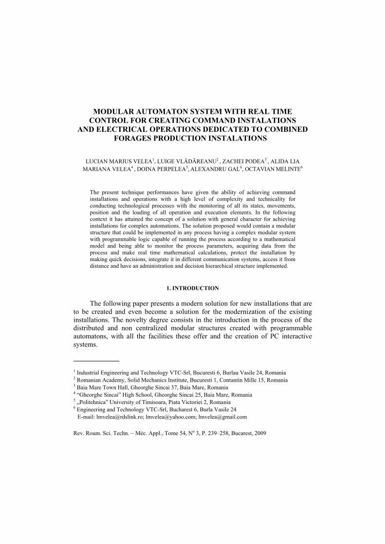
MODULAR AUTOMATON SYSTEM WITH REAL TIME CONTROL FOR CREATING COMMAND INSTALATIONS
AND ELECTRICAL OPERATIONS DEDICATED TO COMBINED FORAGES PRODUCTION INSTALATIONS 1
LUCIAN MARIUS VELEA1, LUIGE VLĂDĂREANU2 , ZACHEI PODEA3 , ALIDA LIA MARIANA VELEA4 , DOINA PERPELEA5, ALEXANDRU GAL6, OCTAVIAN MELINTE6
The present technique performances have given the ability of achieving command installations and operations with a high level of complexity and technicality for conducting technological processes with the monitoring of all its states, movements, position and the loading of all operation and execution elements. In the following context it has attained the concept of a solution with general character for achieving installations for complex automations. The solution proposed would contain a modular structure that could be implemented in any process having a complex modular system with programmable logic capable of running the process according to a mathematical model and being able to monitor the process parameters, acquiring data from the process and make real time mathematical calculations, protect the installation by making quick decisions, integrate it in different communication systems, access it from distance and have an administration and decision hierarchical structure implemented.
1. INTRODUCTION
The following paper presents a modern solution for new installations that are to be created and even become a solution for the modernization of the existing installations. The novelty degree consists in the introduction in the process of the distributed and non centralized modular structures created with programmable automatons, with all the facilities these offer and the creation of PC interactive systems.
1
1 Industrial Engineering and Technology VTC-Srl, Bucuresti 6, Burlau Vasile 24, Romania 2 Romanian Academy, Solid Mechanics Institute, Bucuresti 1, Contantin Mille 15, Romania 3 Baia Mare Town Hall, Gheorghe Sincai 37, Baia Mare, Romania 4 “Gheorghe Sincai” High School, Gheorghe Sincai 25, Baia Mare, Romania 5 „Politehnica” University of Timisoara, Piata Victoriei 2, Romania 6 Engineering and Technology VTC-Srl, Bucharest 6, Burla Vasile 24
E-mail: [email protected]; [email protected]; [email protected]
Rev. Roum. Sci. Techn. − Méc. Appl., Tome 54, No 3, P. 239–258, Bucarest, 2009

240 Lucian Marius Velea et al. 2
For the technological flow creation in order to obtain combined forages dedicated to farm animals, and equipment emplacement, the following have been decided:
▪ technological flow creation; ▪ divide the technological flow into modules; ▪ the components within the modules present in the technological flow; ▪ locate the modules present in the technological flow; ▪ creating solutions regarding the connections that are to be created with the
mills flows. In this context a modular solution has been created that will contain the
following technological modules (Fig. 1): ▪ alimentation module with corn flower; ▪ alimentation module with fineness flours; ▪ alimentation module with cereals; ▪ Micro components measuring module; ▪ unification, P.V.M stocking module; ▪ measuring bunker alimentation module; ▪ macro components alimentation module; ▪ grinding module; ▪ macro components unification module; ▪ granulating module;
▪ stocking and delivering module.
This installation is created with programmable automatons being in a non centralized and distributed structure, ultimate generation programmable automatons, that communicate with each other and with the computer as well using communication protocols.
The communication protocols that are to be used in the installation will be established in the design stage taking into account the imposed requirements.
The splitting of the equipment and the inputs/outputs was done based on the component modules of the “Operation and command modular installation of the line equipment” creating the following technological modules and a modular configuration of the following systems of automation and acting has been done (Fig. 2):
a. silos alimentation module storing raw material – Module 1; b. grits and flour measuring, grinding and homogenizing module – Module 2; c. measuring, homogenizing and medicine stocking module – Module 3; d. liquid ingredients measuring module – Module 4;

3 Modular automaton system dedicated to combined forages production instalations 241
e. granulating module – Module 5; f. delivering, stocking, sacking and bulk goods delivery module – Module 6; g. bag measuring and auto weight module – Module 7. Apart from the modules afferent to the technological flow two more modules
have been created: a. Electrical distribution module – that assures the alimentation and
electrical protection of each and every automation and operating module afferent to the technological modules;
b. PC communication and administration command module Fig. 2. Fig. 1 – Introduction line for combined forages in the technological flow.
SUPPLYING MODULE FOR CORN FLOUR
SUPPLYING MODULE FOR FINE FLOUR
SUPPLYING MODULE FOR REMNANTS
SUPPLYING MODULE FOR DOSAGE BUNKER
MIXING MODULE FOR MACRO-COMPONENTS
STORING MODULE FOR MACRO-COMPONENTS
GRINDING MODULE
MODULE
STORING MODULE
STORING MODULE FOR MICRO-COMPONENTS
P.V.M. MIXING/STORING MODULE

Fig.
2 –
The
com
man
d, o
pera
tiona
l and
par
amet
er m
onito
ring
mod
ular
sche
ma
in th
e te
chno
logi
cal p
roce
ss.
Mod
ule
no.1
Fe
edin
g st
orin
g si
lo
with
raw
mat
eria
l
Mod
ule
no.2
B
eatin
g
MA
STE
R m
odul
e te
hnol
ogic
al fl
ux
driv
ing
Mod
ule
no.3
T
rans
port
and
stor
ing
into
bun
kers
mod
ule
Mod
ule
no.4
re
mna
nts a
nd
mea
l dos
ing
Mod
ule
no.5
p
re-m
ixes
and
m
edic
amen
ts d
osin
g
P.C
. M
AST
ER
E
TH
ER
NE
T
Mod
ule
of d
ata
aqui
sitio
n pr
oces
s fro
m
Mod
ule
no.1
Mod
ule
of d
ata
aqui
sitio
n pr
oces
s fro
m
Mod
ule
no.2
Mod
ule
of d
ata
aqui
sitio
n pr
oces
s fro
m
Mod
ule
no.3
Mod
ule
of d
ata
aqui
sitio
n pr
oces
s fro
m
Mod
ule
no.4
Mod
ule
of d
ata
aqui
sitio
n pr
oces
s fro
m
Mod
ule
no.5
Mod
ule
no.6
p
ile u
nifo
rmiz
atio
n do
sing
Mod
ule
no.7
fa
tnes
s and
m
eteo
nine
dos
ing
Mod
ule
no.8
tr
ansp
ort,
stor
ing,
w
rapp
ing
into
bag
s and
pile
de
liver
ing
Mod
ule
nr.9
tr
ansp
ort a
nd
drus
ing
Mod
ule
nr.1
0 do
sing
into
bag
s and
au
to-w
eigh
ting
Mod
ule
of d
ata
aqui
sitio
n pr
oces
s fro
m
Mod
ule
no.6
Mod
ule
of d
ata
aqui
sitio
n pr
oces
s fro
m
Mod
ule
no.1
Mod
ule
of d
ata
aqui
sitio
n pr
oces
s fro
m
Mod
ule
no.6
Mod
ule
of d
ata
aqui
sitio
n pr
oces
s fro
m
Mod
ule
no.6
Mod
ule
of d
ata
aqui
sitio
n pr
oces
s fro
m
Mod
ule
no.6

5 Modular automaton system dedicated to combined forages production installations 243
2. TECHNICAL SOLUTION PRESENTATION
The projected and built system assures the automatic leading of the micro and macro components measuring flow, connected to a PC, in full-duplex relation with the measuring, delivering, stocking programmable automaton, assures engines operation and execution elements with states and local alarms display on the synoptic panel located on the PC. The system was conceived as being modular with programmable automaton, from the AC500 family, in a non centralized structure which admits its integration in a complex automation and operation installation for delivery-stocking in the silos.
The electrical installation associated to this type of system has the following two components:
• Electrical distribution installation. It contains the distribution circuits, with integrated protection, associated to the technological modules. The installation is created with electrical distribution apparatus: non fixed and fixed automatic switches, fusible port systems, electrical parameters selection and visualization systems and so on.
• Automation and electrical operation installation for module automation. It is created with programmable logic in a non centralized and distributed structure with implementation in modular leading mathematical models with technological flow real time coordination and afferent interconnection. The modular character lies in the fact that the force and automation installation were built from command and operation modules having the same structure. Such a module is built of: central unit, binary input modules, binary output modules or configurable binary input/output modules, configurable analogical input/output modules, RS232 communication module, Modbus, Profibus, Ethernet, electrical operational interface, command interface. The central units communicate with each other using Profibus or Ethernet network, also they communicate with the networks Master unit in order lead the technological process. The Master Unit communicates with a PC to which it sends the equipments and alarms states and from which it receives commands that are forwarded to the installation but also information that is sent over the Internet using GPRS, in order to observe from the distance the installation functionality, and coordinates the functioning of the command and operation modules.
The distributed automation and operation system within technological modules has in general the same structure for all electrical automation and operation modules, having in its component a programmable automaton that will assure the leading of the technological process that is evolved in the specified

244 Lucian Marius Velea et al. 6 module in correlation with the other modules and will communicate with the “Master” programmable automaton that leads the whole technological process and with all the programmable automatons that lead processes in the other modules. The transmission is done using CS31, Modbus, Profibus or Ethernet networks.
The central units communicate with each other using Profibus or Ethernet network, also they communicate with the networks Master unit in order lead the technological process. The Master Unit communicates with a PC to which it sends the equipments and alarms states and from which it receives commands that are forwarded to the installation but also information that is sent over the Internet using GPRS, in order to observe from the distance the installation functionality, and coordinates the functioning of the command and operation modules.
For creating a distributed automation and operation system within technological modules the following have been done: equipment identification within the technological flow, technological equipment operational systems identification, transducers identification needed for the implementation on the equipment, analogical and binary inputs and outputs identification for the programmable automatons.
The module allocation of the binary and analogical inputs and outputs, and the configuration of each module from the electrical device point of view that goes into each modular system structure have been finished.
2.1. THE COMPONENTS IN THE AUTOMATION AND OPERATION SYSTEM
2.1.1. Automation and operation system “silos alimentation module storing raw material” – module 1
It has in as components electrical automation and operation elements for equipments that compose the module: grit and cereal receiving tank, elevator, linear conveyer, emptying clack, entering bunker for storing raw materials, extracting access stoking bunkers using helical conveyers and will assure the Master transmission.
2.1.2. Automation and operation system “Flour measuring, grinding and homogenizing module” – Module 2
It assures the monitoring and leading of the component equipments: scale with force transducers for measuring, emptying clack, measuring bunkers, measuring helical conveyers, evacuation elevator and transporters, homogenizer for dozed batches, fat spreading installation, meteonina spreading installation, grits and cereals grinding mill, throttle clack, evacuation clack, blocking clacks and “Master” transmission (Figs. 3, 4).

7 Modular automaton system dedicated to combined forages production installations 245
Fig. 3 – Associated 1E module – Silos alimentation and storing raw material module.
Fig. 4 – Associated 2E module – Flour and grits grinding and homogenizing module.

246 Lucian Marius Velea et al. 8
2.1.3. Automation and operation system “Measuring, homogenizing, stocking premixes and medicine module” – Module 3
It assures monitoring and leading of the component equipments: for the ones having an automation system with a programmable automaton and electrical operation associated to the equipments that make the module and which will assure the “Master” transmission (Fig. 5). In the same time it monitors the leading of the component equipments: scale with force transducers for measuring, emptying clack, measuring bunkers for premixed substances, measuring bunker for medicine, measuring helical conveyers, alimentation and evacuation transporters and elevators.
Fig. 5 – Associated 3E module – Measuring, homogenizing,
stocking premixes and medicine module.

9 Modular automaton system dedicated to combined forages production installations 247
2.1.4. Automation and operation system “Liquid ingredients measuring module” – Module 4
It assures monitoring and leading of the component equipments: fat transfer pump (oil), evacuation pump, ultrasonic level transducer for fats (oil), electro valves for the fat circuit (oil), meteonina transfer pump, evacuation pump, ultrasonic level transducer for meteonina, electro valves for the meteonina circuit, lizina transfer pump, ultrasonic level transducer for lizina, electro valves for the lizina circuit (Figs. 6, 7).
Fig. 6 – Associated 4E module.
Fig. 7 – Liquid ingredients measuring module.
248 Lucian Marius Velea et al. 10
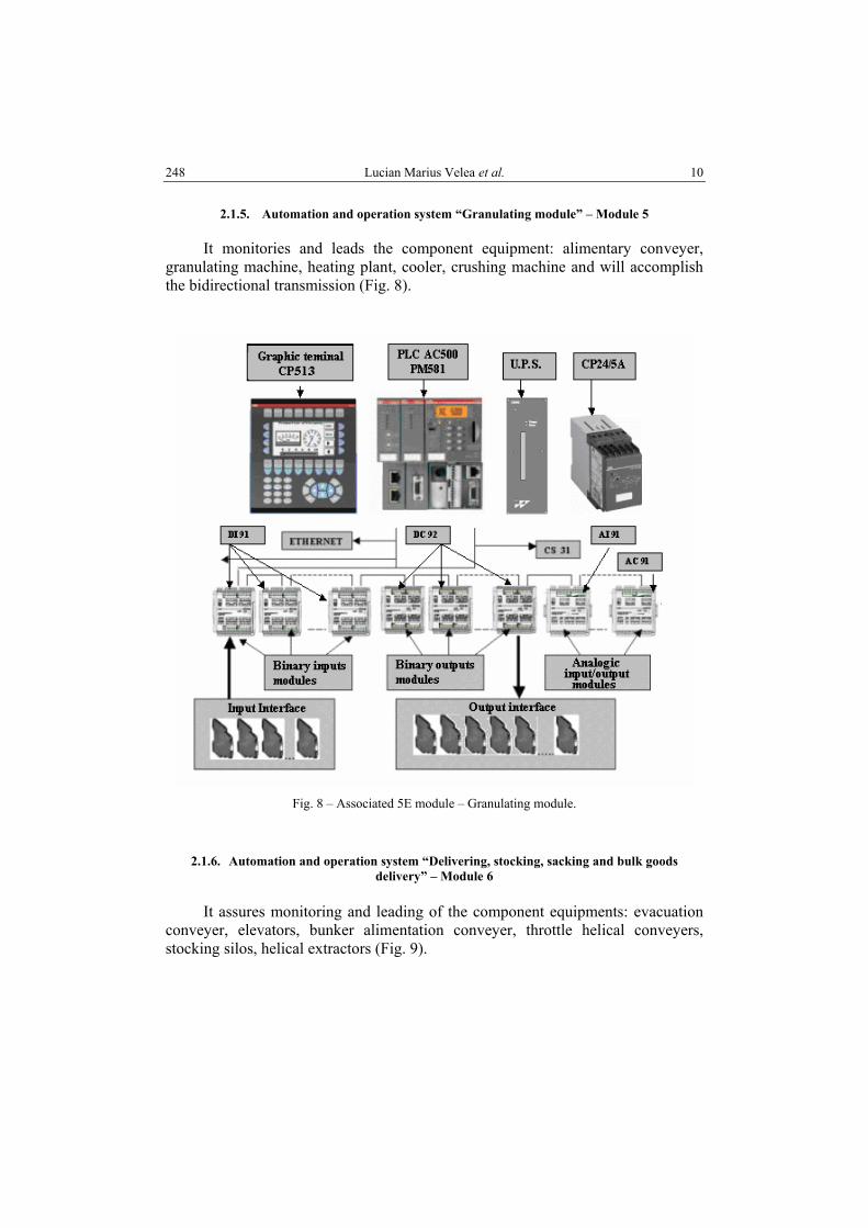
2.1.5. Automation and operation system “Granulating module” – Module 5
It monitories and leads the component equipment: alimentary conveyer, granulating machine, heating plant, cooler, crushing machine and will accomplish the bidirectional transmission (Fig. 8).
Fig. 8 – Associated 5E module – Granulating module.
2.1.6. Automation and operation system “Delivering, stocking, sacking and bulk goods delivery” – Module 6
It assures monitoring and leading of the component equipments: evacuation
conveyer, elevators, bunker alimentation conveyer, throttle helical conveyers, stocking silos, helical extractors (Fig. 9).

11 Modular automaton system dedicated to combined forages production installations 249
Fig. 9 – Associated 6E module – Delivering and stocking module.
2.1.7. Automation and operation system “Bag measuring and auto weight module” – Module 7
It assures monitoring and leading of the component equipments: scale installation for bag measuring, auto scale installation (Fig. 10).
Automatic measuring systems structure: 1. programmable automaton ICS30MBF32; 2. charge cells with sensors of type tensometric mark SAX/I 2 tons; 3. charge cells with sensors of type tensometric mark SAX/I 1 tons; 4. junction box; 5. supply transforming automaton and measuring circuit. From the analysis of the inputs and outputs of the entire system the result is
the electrical configuration for each module:
250 Lucian Marius Velea et al. 12
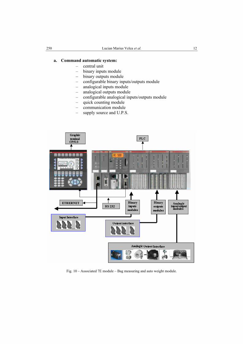
a. Command automatic system: – central unit – binary inputs module – binary outputs module – configurable binary inputs/outputs module – analogical inputs module – analogical outputs module – configurable analogical inputs/outputs module – quick counting module – communication module – supply source and U.P.S.
Fig. 10 – Associated 7E module – Bag measuring and auto weight module.

a. O
utpu
t int
erfa
ce w
ith n
cha
nnel
s for
ope
ratio
ns
Fi
g. 1
1 –
Out
put i
nter
face
with
n c
hann
els f
or o
pera
tions
.

252 Lucian Marius Velea et al. 14
2.2. IT SYSTEM (INFORMATION & TECHNOLOGY)
Coordination administration of the technological flow with PC observation and distance transmission over the Internet. It is located at a certain distance having the capability of receiving the transmitted data using Profibus and Ethernet communication networks from programmable automatons within the process, data that can be: process or electrical parameters, equipments state parameters, distance alarms and commands, measured and programmed networks, being able to save, display and transmit when requested over the Internet.
The system is conceived as being one of the authorized persons so that it can observe the installation functioning, of the whole flow over the Internet though without having the option of commanding the equipments in the flow. The synoptic schema associated to the technological flow will create a display with big resolution. The administration contains a server block that consists of the database server, web server and the control and command block for saving and information processing (Fig. 12).
Fig. 12 – PC communication and administration command module.

15 Modular automaton system dedicated to combined forages production installations 253
In a distributed architecture the work is divided between multiple units: the acquisition and local processing of the measured values, controlling some of the local adjustment loops; only the monitoring part continues to be centralized.
A supervisory control for coordinating the technological flow with monitoring on the PC is obtained using a graphical interface, which makes an information system.
For creating the graphical interface on the PC, based on the graphical drawings representing the technological flow containing all installations and the data received from the master programmable automaton (the electrical or process parameters, the equipments’ state parameters and the distance alarms), the development of the application was done using C# language, on .Net Framework platform, the development technique shortly presented in what follows.
Technical solution presentation
A. Reading data
The data retrieved from the process by the programmable automatons are sent to the PC using a communication network and an associated communication protocol the application storing it in a memory location after reading it from a COMi port.
From the memory buffer the data will be processed and stored in the objects corresponding to their associated modules from the modular, decentralized and distributed structure.
The data from the process are provided by a programmable automation, the communication being done using a direct connection on RS232 port.
The PLC provides simple data which is represented by an array of bites, a bit being able to represent a state of one of the components from the system, and 2 bytes (1 byte = 8 bits) being able to represent a scalar value, being one of the heights or the current intensity belonging to a component.
This data is used for updating the graphical interface according to the equipments’ state.
For successfully reading the data, the PLC and the PC need to be synchronized, this being done by a setting available when starting the application (Fig. 13).
Handshaking. This setting offers the processor a mechanism for coordinating the data transfer between the PC and PLC, because the PLC is capable to send a number of hundred thousand bits, and PC might not be able to process such a volume of data.

254 Lucian Marius Velea et al. 16
Fig. 13 – Graphic interface application.
Once the settings are done and the application successfully connected to the PLC, the values selected are saved, and the next time the application is started, the values will already be selected on the start window (exception being the serial port). After successfully started the application another window is visible for the user, this one making available a number of buttons, each button representing a module from the technological from for which the PLC provides data (Fig. 1).
For monitoring a module from the process, the user clicks the corresponding button, the window having the technological flow being replaced with another having the selected module, for example in Fig. 14. The module interface (numerical data, the color of the boxes) changes depending on the data read from the PLC.
B. Updating the data in the windows
The data updated in the windows represent:
1. parameters for electrical engines, bunker heights; 2. equipment state parameters; 3. distance alarms.
Application architecture. Because of the functionalities made available, the application is based on a 3-layers architecture. The advantage of implementing such architecture is:
• Offers modularity to the application, in this way being easier to modify a layer without affecting the existing ones;

17 Modular automaton system dedicated to combined forages production installations 255
• Offers a bigger scalability for a bigger number of users; • Separating the applications business functionality and data acquisition
offers a balance between the two, and in this way the application is able to function in real time.
Fig. 14 – Tehnological flow with the selected modules.
The application is responsible for data acquisition from the PLC, in this way
having a client role. The class handling the data acquisition and notification to the user interface or GUI about the new data acquired is SerialPortCommuniction.
The PLC sends 174 bytes, each of which represents a scalar value for the heights or the current, alarms or equipment state. For alarms and the equipment state the processing is done at bit level.
The rendered data are stored in their objects, each object having members representing heights, currents, alarms or states. In Fig. 15, the Synoptic Panel on the PC is presented together with the values of the monitored parameters.

Fig.
15
– Sy
nopt
ic p
anel
on
PC w
ith th
e va
lues
of t
he m
onito
red
para
met
ers.

19 Modular automaton system dedicated to combined forages production installations 257
3. CONCLUSIONS
In order to create such installations the current authors have created the following objectives that are in compliance with the objectives of the National Program – INOVATION:
• The determination of a technical solution based on a thorough research against creating a complex modular command installations with programmable automaton PLC and PC interface for obtaining higher performance at a smaller price.
• Creating an automation system having programmable automatons in a decentralized structure and positioning modules, posting modules and frequency convertors managed by the programmable automaton for the actions imposed by the system connected to a computer.
• Choosing a modern technical solution for reengineering the existing installations belonging to a company but also creating the production installations for the new combined forage
• Introduction of top technology as a solution for increasing reliability and safety in operations.
• Automation of the production process that should reduce the human effort. • Thorough studies on controlling, commanding and manage the execution
elements and also on creating distance administration systems. • Creating and applying products and technologies by the contractor in
collaboration with the research units by applying the top technologies according to the international standards.
• Modernization of the existing products and technologies done by the contractor in collaboration with the research units.
• Increasing the quality and technical level of the created products, the reliability, durability, accuracy, precision and safety degree in the functionality and creating ecological products on its entire lifetime cycle.
• Increasing the performances of the used technologies by optimizing the energetic and raw material consumption, applying quality and environmental standards.
• Reducing technology loss caused by the optimization of the production process by using top techniques and PC supervising.
• Production process quality increase for obtaining the final product.
Received on 29 May 2008
258 Lucian Marius Velea et al. 20
BIBLIOGRAPHY
1. Velea L. M., Vlădăreanu L., Drumea M., Interactiv automation system for data acquisition for driving technological processes type S.A.I.A.D., International AMSE, MS’ 2000 International Conference on Modelling and Simulation, Las Palmas de Gran Canaria, Spain, 25–27 September 2000, pp. 463–471.
2. Vlădăreanu L., Velea L. M., PLC Architectures in Distributed and Decentralized Structures – a new step towards top technology, International AMSE, MSNN – 2000; International Conference on Modeling, Simulation and Neural Networks, Merida, Venezuela, 22–24 October 2000.
3. L. Vlădăreanu, L.M. Velea, Open Architecture Systems for Real Time Control of Robots’ Structural Vibrations, World Scientific and Engineering Academy Society WSEAS, ESPOCO’2005, Rio de Janeiro, Brazil, April 25–27, 2005, no. 494–150, pp. 47–53.
4. Luige Vlădăreanu, L.M. Velea, Complex automations bases using programmable automaton, Edit. Mediamira, Cluj-Napoca, 2005, p. 250.
5. Lucian M. Velea, Radu Munteanu, Complex Automatization for Compline Leading in Open Structure of Multiaxis Systems, Advanced Engineering in Applied Mechanics, Edit. Academiei, 2006.
6. Vlădăreanu L., Velea L.M., Use of Programmable Logical Controllers for Implementation of the Damper Control Systems, Sixth International Symposium on Active Noise and Vibration Control (ACTIVE 2006), September 18–20, 2006, Adelaide, Australia, Australian Acoustical Society, pp. 331–340.
7. Vlădăreanu L., Velea L.M., Hierarchical structure based on PLC and implementations in top technologies from various fields of economy, International AMSE, MS’ 2000 International Conference on Modelling and Simulation, Las Palmas de Gran Canaria, Spain, 25–27 September 2000, pp. 643–651.