modular, adaptive, reconfigurable systems: technology for
TRANSCRIPT

. -
Modular, Adaptive, Reconfigurable Systems: Technology for Sustainable, Reliable, Effective, and Affordable Space
Exploration
Jaime Esper
NASA Goddard Space Flight Center, Greenbelt, MD 20771 (301) 286-1 124; [email protected]
Abstract. In order to execute the Vision for Space Exploration, we must find ways to reduce cost, system complexity, design, build, and test times, and at the same time increase flexibility to satisfy multiple fimctions. Modular, Adaptive, Reconfgurable System ( M A R S ) technologies promise to set the stage for &e del ivq of system elements that form the buildmg blocks of increasingly ambitious missions involving humans and robots Today, space systems are largely specialized and built on a case-by- basis. The notion of modularity however, is nothing new to NASA. The 1970's saw the development of the Multi-Mission Modular spacecraft (MMS). From 1980 to 1992 at least six satellites were built under this paradigm, and included such Goddard Space Flight Center missions as SSM, EWE, UARS, and Landsat 4 and 5. Earlier versions consisted of standard subsystem "module" or "box" components that cwld be replad witbin a structure based on predefined form hctors. Although the primary motivation for MMS was fastedchqer integration and test, standardization of interfaces, and ease of incorpomting new subsystem technology, it lacked the technology maturity and programmatic "upgrade infrastnactm?e" needed to satisfy varied mission requirements, and Uttimately it lacked user buy-in. cwsequently, it never evolved and was phased out !Such concepts as the Rapid Spacecraft Development Of€ice (RSDO) with its regularly updated atalogue of prequalifkd busses became the preferred method for acquiring satellites. N o t w i h ~ n ding, over the past 30 yems since MMS inception, technology h a advanced considerably and now modularity can be extended beyond &e traditiod MMS module M
box to cover levels of integration, from the chip, card, box, subsystem, to the space system and to the system-of- systems. This paper will present the MARS architecture, cast within the historical context of MMS. Its application will be highlighted by comparing a state-of-the-art point design vs. a MARS-enabled lunar mission, as a representative robotic case design.
BACKGROUND
Ignorance is bliss. Over the past two years the NASA Goddard Space Flight Center (GSFC) has worked to develop modular and reconfigurable system technology. Although this concept has evolved over time to adapt to changing requirements, the initial approach has remained steam: to find ways to streamline the life-cycle process in the production of space assets. The expectation is that in doing so, the cost of designing, building, integrating, testing, and flying space systems will be reduced making them affordable across-the-board to human and robotic exploration. Sounds familiar? Some of us have been around enough to have heard and experienced the Multimission ModuIar SpacecraSt (MMS), conceived m the 1970's and developed and implemented in the 1980's and 90's. Notwithstanding the wealth of ideas and experience &ed &om MMS, the Modular, Adaptwe, Reconfigurable System (MARS) architecture has sought to reapproach the problem in light of technological advances made over the last 30 years. In domg so, it was necessary to attack the question of modularity, adaptability, and reconfigurability without previous bias, i.e., without in-depth knowledge of MMS. This "fiesh blood" has reached some conclusions, a few with sm'king resemblance to those reached during the times when M M S was being formulated, designed and developed. So indeed, ignorance is bliss, in that it injects a sense of "newness" to an old approach. But the good news is that hindsight is also 20/20. By comparing the current approach with the lessons learned through the development of MMS, NASA is in a unique position to correct those elements that did not work then, and thrust M A R S technologies into a new era of achievement: Exploration. It is also true that as technology has leaped over 30 years, concepts proven to be either impractical or deficient can now be implemented
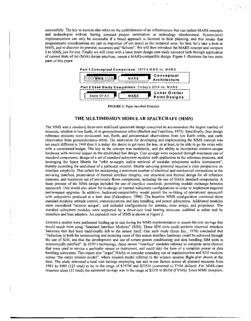
successfully. The key to success also relies on the establishment of an infrastructure that can update MARS concepts and technologies without fearing constant project termination or technology obsolescence. System-level implementations can only be successful if a broad approach is factored in their planning, and that means that programmatic considerations are just as important (if not more) as the technical ones. So first, let’s take a look at MMS, and re-discover its premise, successes and “failures”. We will then introduce the MARS concept and compare it to MMS, just for size. Finally we will close with a lunar point-design case study executed both through application of current State of Art (SOA) design practices, versus a MARS-compatible design. Figure 1 illustrates the two main parts of this paper.
C o n c e p t u a l i Arch i tec ture i
: IC r t L u n a r O r b i t e r i : State Of A r t P o i n t D e s i g n s i
FIGURE 1: Paper two-Part Structure
THE MULTIMISSION MODULAR SPACECRAFT (MMS)
The MMS was a standard, three-axis stabilized spacecraft design conceived to accommodate the largest number of missions, whether in low Earth, or in geosynchronous orbits (Bartlett and Cepollina, 1975). Specifically, four design reference missions were envisioned: sun, Earth, and astronomical observations from low Earth orbits, and earth observation from geosynchronous orbits. The motivation for developing and implementing the MMS concept was not much different in 1969 than it is today: the desire to get more for less, or at least, to be able to go the extra mile with a constrained budget. The key to the concept was modularity, and the ability to incorporate mission-unique hardware with minimal impact to the established bus design. Cost savings were expected through maximum use of standard components, design of a set of standard subsystem modules with application to the reference missions, and leveraging the Space Shuttle for “orbit re-supply and/or retrieval of modular subsystems and/or instruments”, thereby extending the usefulness of a particular mission. Shuttle servicing potential required a clear perspective on interface simplicity. This called for maintaining a minimum number of electrical and mechanical connections at the servicing interface, preservation of thermal interface integrity, one structural and thermal design for all reference missions, and maximum use of previously flown components, including the use of NASA standard components. A basic premise of the MMS design included the use of interface standards, permitting module exchange between spacecraft. This would also allow for re-design of internal subsystem configurations in order to implement required performance upgrades. In addition, backward-compatibility would permit the re-fitting of operational spacecraft with subsystems produced at a later date (Falkenhayn, 1988). The baseline MMS configuration contained three standard modules: attitude control, communications and data handling, and power subsystems. Additional modules were considered “mission unique”, and included configurations for antenna, solar arrays, and propulsion. The standard subsystem modules were supported by a thrust-axis load bearing structure, outfitted at either end by transition and base adapters. An exploded view of MMS is shown in Figure 2.
Extensive studies were performed leading up to and during the MMS implementation to assess the cost savings that would result from using “Standard Interface Modules” (SIM). These SIM units could perform electrical interface functions that had been traditionally left to the sensor itself. One such study (Econ Inc., 1976) concluded that “reduction in both the nonrecurring and recurring costs of this sensor interface hardware could be achieved through the use of SIM, and that the development and use of certain power conditioning and data handling SIM units is economically justified”. In 1970’s technology, these sensor “interface” modules referred to complete units (boxes) that were used to service a particular sensor or instrument, and could take the form of a complete power or data handling subsystem. This report also “urges” NASA to consider extending use of standardization and SIM modules across “the entire mission model”, where mission model referred to the science mission flight plan drawn at the time. The study estimated a total cost savings employing use and re-use factors across all planned missions from 1981 to 1985 (125 total) to be in the range of $197M and $235M (converted to FY04 dollars). For MMS-class missions alone (31 total), the estimated savings was in the range of $53M to $63M (FY04$). Since MMS inception,

6 spacecraft have flown under its umbrella. These include the Solar Max Mission (SMM) in 1980; Landsats 4 and 5 in 1982 and ‘84, respectively; the Upper Atmospheric Research Satellite (UARS) in 1991; the Ocean Topography Experiment (TOPEWPoseidon) in 1992; and the Extreme Ultraviolet Explorer (EUVE) in 1992. This is a far cry from the 3 I expected in the 1970’s, and it remains uncertain exactly what the actual cost savings were. By some account, the main cost advantage of MMS was the reduction in Integration and Test (I&T) times. Timeline savings in I&T ranged from 50% to 80% (Falkenhayn, 1988), by comparing such spacecraft as Landsat 5 and UARS (MMS), versus TIROS, COBE, and GOES (non-MMS). Recent analysis of modular and reconfigurable spacecraft cost savings are in rough agreement with the 55% to 65% savings expected in 1988 from using an MMS approach. Assuming initial costs for development and production between a MARS-compatible spacecraft and custom-made spacecraft are set equal, over a 6-spacecraft series the MARS spacecraft would cost about 67% less to develop and produce than their counterparts. Setting a production unit limit such as “6” is convenient, in the sense that it provides a realistic sequence before a major revision to the design should be undertaken. This of course does not mean that major changes are necessary in the case of the MARS architecture, since flexibility is built-in by design. In addition, an established technology program would ensure that technology obsolescence does not result in dramatic changes to the evolutionary, “spiral” development.
FIGURE 2. The Multi-mission Modular Spacecraft (Bartlett and Cepollina, 1975)
The MMS program made important contributions to I&T processes and procedures (Greenwell, 1978). In the early days at GSFC, complete prototype spacecraft were produced and tested to environmental levels greater than those

expected under operational conditions, in order to demonstrate design margins of safety. After proving hardware so tested would not be degraded, GSFC developed the “protoflight” concept. Instead of building an entire copy for testing alone, protoflight hardware was built and tested to prototype levels but for durations normally used to test flight hardware. This saved the cost of producing hardware intended for testing alone. Protoflight testing was usually applied to the first unit in a series, but not to the production units. Testing at the module level was favored over component or spacecraft system (sans the payload) testing. This was a reasonable approach, as it was envisioned that modules would be produced by different vendors and integrated already pre-qualified into a flight system on the ground, or as replacement units for orbiting spacecraft. Testing at the “payload” or observatory level was still executed, but that was the responsibility of the project end-user. Many concepts developed during MMS were incorporated into the defacto standard for spacecraft testing contained in Goddard’s General Environmental Verification Specification (GEVS) for STS and ELV payloads, subsystems, and components, and applied in spacecraft servicing such as SMM and Hubble Space Telescope (HST).
After the successful repair of the first MMS spacecraft, the Solar Max Mission, NASA decided MMS would become the Explorer Program platform of choice. The Explorer Program, which began in 1958, has flown a long line of relatively low-cost, small-to-moderately sized missions. Although the first such platform using MMS was the Extreme Ultraviolet Explorer (EUVE), a follow-up mission, the X-Ray Timing Explorer (XTE or Rossi-XTE), did not materialize. The XTE spacecraft, launched in 1995 and developed at NASA GSFC contained “an impressive” number of innovations compared to the MMS Explorer Platform that was originally going to serve the mission.
XTE exemplifies one of the major objections to MMS that can be gathered from researching the historical references. The EUVE became the first MMS spacecraft being enhanced by an additional flight computer (Scott, 1989). The original NASA Standard Spacecraft Computer (NSSC-I) was simply not fast enough to service the computing requirements of the science instruments. It was decided to augment the Communications and Data Handling subsystem with an additional co-processor. Further, significant modifications to the Landsat MMS Modular Attitude Control Subsystem (MACS) were required to satisfy the TOPEWPoseidon performance needs (Williams, et al., 1990). The MACS inherited by the project had been based on 1970’s technology, and hence had severe limitations for 1990’s standards. In fact, technical modification for MMS technologies was left to individual projects by design. The rationale was that the previous project would pick up the non-recurring costs in updating and upgrading components to current technology standards. Hence, there was no central “technology program” in place that would advance modular components, or maintain a selection of options that could be used by a particular customer. Although the original premise was based on sound judgment, without a central driving force, projects had no incentive of using “someone else’s design”. From an industry perspective, competitive forces also encourage the proposal of “best” or “better” designs, and disinterest in MMS with its sets of standards was a natural evolution.
Another less intuitive reason for the “abandonment” of the MMS concept lies in the Space Shuttle. Plans for using the Shuttle for launching and servicing of unmanned spacecraft suffered a critical set-back, especially after the 1986 Challenger accident. First, the Shuttle itself became a less attractive workhorse for launching and servicing unmanned spacecraft due to risk and cost concerns. Second, the decision to scrap launching Shuttles fiom Vandenberg curtailed the servicing plans for a number of spacecraft that were to be injected into polar orbits (Leete, 2001). The economy of scales for serviceable spacecraft began to lose its impetus. Only great observatories (HST) and the International Space Station would stand a chance at using the Shuttle for recumng visits, and up to this date continue to reap the benefits of a modular design. Today, with the resurgence of a robotic HST servicing, with space station, and the Vision for Space Exploration, there is a renewed impetus in modular systems.
Finally, in a world of large launch vehicle costs, optimization of system mass is more than a trivial exercise. Indeed, with a typical 30% or more increase in cost between launch vehicle classes, projects are forced to take any mass- saving (or other relevant) measures available to them. For a $lOOM project, $30M budget overrun spells serious trouble, and depending on particular conditions, even a modest 10% increase in mass could push it over the edge.
The legacy of MMS has been far-reaching in the world of space exploration. The pioneering endeavor of its founders has served as a catalyst to many of the space platform implementations of today, and promise to be an inspiration for the generation to come. Next, a description of what these platforms might be is presented, and a comparison with MMS successes and limitations is offered.

MODULAR, ADAPTIVE, RECONFIGURABLE SYSTEMS (MARS)
MARS is a gstem-level architecture that comprises all elements of a space mission extended life-cycle, including ground and space segments. MARS establishes a broad system-level architecture upon which technologies can be developed. Exactly what it means for a technology to be MARS-compatible will be explained, to some extent. However, definitions here are not intended to be rigid, as t h i s would be contrary to the basic paradigm of adaptive and reconfigurable systems. R&er, as technologies reinvent themselves, so do the definitions concerning what it means to be h&%RS-annpah%le. Likewise, the MARS conceptual definition may change, and in dobg so drive technology to some natural evolution. This is an iterative, constantly evolving process. Any static definition of an architecture that has ‘‘adaptive” and ‘teconfigurable” m its term would simply be counterproductive, or at the very least, transient.
The defining terms offend far MARS may be thought of as “initial“, or ”boundary umditim”, in the traditional sense ofthe win. These *bo* um&rionS, which facior both pmgmmmatic and h h i c a l concerns, are used to develop a particular solutim domain containing a set of technologies. Again, technology evolution and programmatic mcems can necessitate the changing of these initial conditions. This is one key result of &e 2olto hindsight obtained from MMS. There are neither “standard boxes” nor “standard spacecraft”. Even “scandard interfaces”, a key element of MARS, lire allowed to evolve over time. Insofar as int&hces are known to evolve at a slower rate than technologies though, they qualify here for the term “standard”, with a caveat.
So what are the basic premises d to set the stage for development of MARS technologies and systems? They are summarized below. But first, a few definitions are in order.
MARS Definitions
Clear definitions are important for providmg the context upon which MARS technologies are developed.
Modular.- MARS systems wntain selecgble Illt;chiizIlcal . , electrical, and software cmqonents that may be used and re-used in quantized numbers. Modular (or quantum) components used m a system must be capable of evolving to incorporate advances in technology, and they must accept standard intdaces and plug-and-play principles (e.g. P e r ~ o ~ l Computers). Collectively (and individually) MARS modular components and systems must result in intelligent units, referring to their ability to assemble into larger components or systems on the ground or on-orbit. A module can have varying ZeveZs of integration, from the chip to the card, box, subsystem, system, and system of systems. As an extension of the above, a module is capable of effecting a “function” either by itself, or as a conglomerate system.
True today as it was 30 years ago, plug-and-play interfaces are not yet implemented in space flight systems. The ability to recognize components autonomously as they are added to a modular system is a key in realizing schedule savings and streamlining integration and test. This is important for astronauts on a moon or Mars base, or for cost- savings on the ground.
Adaptive: This term is used along the lines of the classic control systems definition. In simple terms, and uaI7.pti.e control system is one that is capable of learning from its environment, and acting accordingly. An adaptive MARS
changing raquirernents, whether they are precipitated through an a priori definition (I did not intend for the system to do this, but now that you mention it, by design it can adapt), or autonomously required on the field based on previously unanticipated events.
This concept is entirely new, and had not been entertained by the Mh4S design. Rather, due to technological limitations MMS relied more on standard subsystems designed to accommodate the largest number of missions a priori. Missions that fell outside of this design envelope were better served by one-of-a-kind approaches.
Reconfgurable: The system must be capable of morphing in order to apply to a host of missions. It also must be easy to produce, integrate, test, and launch, and it must be capable of operating alone or as a collective part, physically detach or attach. Reconfigurable systems are considered at varying scales, from electrical components and MEMS, to whoie spacecrafi, or pieces of a moon base. it differs from adaptabiiiry in the sense rhar
. . system would permit reconfiguration of its mechanical (including thermal), electrical, or software c- cs to

reconfiguration is expected based on a set of known boundary conditions. A system may be reconfigurable, yet not be capable to adapt to changing requirements in certain cases. However, a system that can adapt is always reconfigurable in that particular instance. MMS can best be described as a reconfigurable-only system, within the limited set of missions for which it was conceived.
System: Normally, one should not have to define what a “system” is. Yet, there may be as many definitions as there are engineering disciplines. The MARS architecture allows all as it should: a “system” takes on as many incarnations as there are modules. One could consider an atom as being the most elemental “module” (true, one could go even smaller), and indeed it is a system composed of protons, electrons, and neutrons (the simple model). For practical purposes, a system is an entity that carries out a specific function, whether it is to open and close tiny MEMS “Venetian blinds” (variable emissivity coating), distributes power over an entire spacecraft, or coordinates construction tasks among multiple robots and humans. The important thing to remember is that the MARS architecture is not limited to small or large systems: it can be as broad or as narrow as required. This broad application of the MARS architecture stands in stark contrast to the MMS design philosophy of only modularizing three key subsystems: attitude control, communications and data handling, and power subsystem. Levels of modularity or integration are then used in MARS to provide the reconfigurability to satish a broad range of pre- defined mission classes, or the adaptability to adjust to unexpected mission requirements.
MARS Systems Design Methodology
The basic design methodology for MARS spacecraft and systems is summarized as follows. Note that these are only broad suggestions in what is hoped to be a reasonable set of principles to follow. However, alternative concepts are not only welcome, but also expected as the space community finds the best implementation approach for the evolving times.
MARS spacecraft and systems should take advantage of multi-billion dollar commercial standards for manufacturing, computing, and communications technology. This results in sustainable systems, where not only the government is the contributing source of funds to maintain technology relevance.
The Modular design architecture must be capable of advancing along with technology improvements. In other words, the “module” can contain technology relevant to its time, and is not fictitiously constrained to some “standard”. Although this was also a basic premise of MMS, no technology program was ever established to allow for technological evolution, leaving modules stagnant. Loss of interest in MMS roughly coincides with the need to re-design the “standard” subsystems and components.
Standardization is implemented at the interface, not at the subsystem or system level. Electrical interfaces should use commercial standards, such as Ethernet, Firewire, USB, and others. Mechanical and fluid interfaces should also be standard and flexible enough to accommodate various layout configurations. Specialized interfaces can be developed only if required for a particular set or sets of applications. Components should attach via standard interface much as peripherals attach to a computer. Each “peripheral” would need to come with its software driver. The driver is either pre-loaded in the operating system, or loaded as needed by the user. Mechanical and fluid interfaces represent a special challenge, since there is currently little use of standards, except in the launch vehicle industry or for space station applications.
Standard interfaces were also a key element of MMS. However, technology had not evolved enough to make these interfaces plug-and-play (PnP). In fact, interfaces in the MMS times were so closely connected to the internal design of a subsystem, that changing it internally required a re-definition of those same interfaces. In addition, in the 1970’s, reference to an interface often times referred to a complete subsystem or hnctional box, used to “interface” to the science instrument or payload and provide some quantifiable service, such as power. The slippery slope of “interface standards” can be tracked down to the level at which this interface is implemented. For the case of electrical interfaces, if all that is needed to convert an electrical signal to a pre-defined standard is either change a chip or card in a sensor, subsystem, or component, then designers may be more willing to comply. If on the other hand, compliance means re-designing the whole thing, the ensuing expense will very quickly transfer to the customer or end-user. Today, h P interface standards can be used to service an instrument or component in such a way as to become immediately recognizable to the system. This flexibility was simply not available before.
--
Choice technologies (not standard) may be incorporated, with a list reviewed and updated at regular intervals to maintain technological relevance.
There was f?equent reference to “standard components” and “standard subsystems” or “standard technologies” in the 1970’s and 80’s. It appeared that every other concept presented had its own “standard” proposal. Technologies like the “NASA Standard Spacecraft Computer (NSSC)” originate from these times. Given the rapid evolution of technology, in particular computing technology, this standard fell quickly far behind. As there was no technology development program in place to quickly replace those “standard components”, obsolesceace in designs quickly set it, unchecked. The HST was one of those spacecraft outfitted with a “second generation” NSSC computer. A co- processor was eventually installed on-orbit to supplement the original computer’s capacity.
The system should use commercial, open code aperating systems &e., Linux). This enables the incarporation of a common, flexible operating system that encourages industry involvement and stimulates mta-operablity among
system need to follow suit. Nobody expects to use Windowsm 95 today . . . at least not if there is a desire to take advantage of superior graphics, higher speed, and of course, the ultimate in video 5 1 2 s . This is not to say that proprietary operating systems are “forbidden”, just that that they must be compatible with the open code operatmg systems.
The flight software should be based on a layered architecture, with maximum re-use of infrastructure and application modules. No doubt, software technology has improved leaps and bounds since the MMS days. Today, software can be developed which is completely independent of the platform or operating system. One of the key factors in the success of the PC platform for instance, is the choice and backwards compatibility afforded between many different types of hardware and software. This is made possible by the BIOS (Basic InpdOuput System) and the software layer model. The system BIOS acts as an interface between the hardware and the computer Opwating system, on top of which the application layer resides. Each layer communicates to the layer below through a standard interjhce. This way neither the operating system nor the application layers ‘‘care‘’ which the hardware host is. The Open Systems Interconnect (OSI) Reference Model also defines a modular approach to networking, with each layer (module) responsible for some specific aspect of the networking process. W i e r attempts at so- development had more to do with defining standards for High Order Programming Languages (DiNitto, 1978), than concentrating in standard interfaces between highly portable software modules.
Communications and information exchange should be done directly from the user to the spacecraft through distributed internet-based operations. The ensuing architecture calls for the use of spacecraft and space systems as point extensions on the Internet.
Of course, MMS was before A1 Gore. The “information super-highway” had not been invented, and did not really “take” until the early 90’s. A message from the spacecraft would look more like a Commodorem 64 command line than a colorful, radiometrically calibrated image of a M d a n rock. Commands to the spacecraft would have to go through specialized methods, originated by computers the size of mini-vans. The concept of a comfortable work- station at home was relegated to reading and interpreting computer print-outs of cryptic telemetry “1s” and “Os”, while sipping coffee at 3.00 o’clock in the morning. The ability to command a spacecraft, and receive immediately- meaningful telemetry from that same location was unheard of. The point: the internet today allows connectivity that is incomparable to anything the space industry has seen in the past. Taking advantage of its benefits should be of utmost importance in the way we operate, portray, and exchange information among ground controllers, users, astronauts on the moon or Mars, and the public at large.
Table 1 shows a comparison of MMS and MARS concepts and operating principles. Note the similarities, but more importantly, the significant differences that result firom 30 years of technology evolution, and hindsight. MMS was an important trailblazer for today’s MARS systems and without it we simply could not have evolved to where we are today.
p.”;.Oers. y . .,. I- -., en- Juoi;ld .-l. be exercised: ju? is +a?zxAap’ chimp, sc t.~r& in %e qm&g

Characteristic MMS Modularity Implemented primarily at the subsystem
level.
Adaptability Not implemented.
class of missions.
MARS Uses levels of integrafion, where a module can be a MEMS device, electronic chip, card, box, subsystem, system, or system-of-
System capable of learning and acting either a priori, or real-time from its environment. The system is entirely morph-able in order to apply to a host of missions. Made possible by modular levels of integration and adaDtabilitv.
MMS The supporting infrastructure did not develop as expected, requiring Shuttle flights, broad spacecraft servicing, and individual project buy-ins. Relied on individual projects for technology development.
Primarily at the box or subsystem level.
Key Area Sustainability , affordability
MARS Leverage multi-billion dollar commercial standards for manufacturing, computing, and communications technology.
Relies on establishment of a technology program that can cany evolutionary changes in spiral developments. Standardization at the interface only. Choice
Technology Relevance and effectiveness Standardization, reliability
- -. _ _ _ _
Spacecraft Operating System
Flight Software
_ _ _ - - - _.__ .. -. .. _ _ .. . . . Data Transport
One-of-a-kind, often proprietary implementation.
One-of-a-kind, often proprietary imnlementation. Svstem
interchangeable software modules. Based on a modular layered architecture, with maximum re-use of infrastructure and
Distributed internet-based command and data flow.
application modules. -
One-of-a-kind, often proprietary implementation.
technologies, rather than “standard;’ that are updated regularly on a well established spiral development approach. Open code architecture. Adoption of one or two compatible Operating Systems with
CASE STUDY: LUNAR ORBITER
Since late 2002, the GSFC has been taking a fresh look at modular and reconfigurable system technology. Three integrated design exercises have been carried out, each time enhancing and fine-tuning the MARS architecture. The general approach has been to first consider what makes a system compatible with MARS, and then apply those principles to the development of specific point designs. In February of 2004, one such exercise led to the comparison of a traditionally developed robotic mission to the moon (SOA design), contrasted against what it would look like should MARS principles were to be applied. Although detailed quantitative results of this analysis are beyond the scope of this paper, key results are summarized here.
The original mission’s objective was to carry out remote sensing observations of the lunar poles simultaneously while a rover explored the surface for evidence of water. The approach was to use a Rapid Spacecraft Development Office (RSDO) catalogue spacecraft, and modify it to satisfy mission objectives. The original design called for the use of an advanced EO-1 derivative carrying a “Sojourner” type rover and outfitted with Pulse Plasma Thrusters (PPT) for attitude control, GaAs solar arrays, X-band phased array antenna, a 40 Gbit solid-state recorder, and a Fiber Optic Data Bus (FODB) capable of data rates up to 840 Mb/s. Spacecraft parameters for this design are summarized in Table 2. This design represents a typical example of balance between heritage and advanced components. For this reason, the mass and power estimates can be considered optimum and representative of a one- of-a-kind design, even though an RSDO spacecraft core was used as a starting basis. Mass and power results would have been significantly higher, had advanced technologies not been used (Esper et al., 1999). The total spacecraft wet mass was estimated at 714.2 kg, with about 5% margin allocation for launch on a Delta I1 7325. Since the

February 2004 exercise concentrated in redesigning the orbiter portion of the mission, the lander wet mass was simply camed as reserve.
Space& PayloaCr UVNISINIR H y p e r s p e c h i Imager long IR LIDAR
TABLE 2
11.5 89.0 2.3 5.0 5.8 17.0
: Spacecraft parameters resulting from the use of current design practices (Esper, et al., 1999) 1S.b.y.f.m I Yass(kg) I PoweroN)’] Structure 93.0
- - Attitude Control 8 Data System Electronics 19.0 38 Attiiude/Reaction Control System (using PPT)‘ 12.9 43 Power System (w/ Advanced GaAs Arrays)” 58.1 33 Solar A m y Mechanisms 16.5 Harness 29.0
Performance (mass, power, volume) budget allocations were assigned to each spacecraft subsystem in accordance to MARS architectural principles, including spauxraft classification based on expected launch vehicle use. The r e designed lunar mission estimated spacecraft parameters based on both, budget allocations, as well as using ”actual” estimates from each engineering discipline. In the former case, the mass estimates resulted in about 5% i n m e fiom the original design. Surprisingly however, the latter w e resulted in about 20% spacecraft mass savings from the original design. The reason for this lies in the fact that an RSDO spacecraft core is not necessarily an “optimum” design, and modularity at the system level had already been factored into it. Notwithstanding, results do show that when MARS principles are applied in an ‘‘~ptimum’’ manner, results can actually be better than just simply using heritage components or systems. This is because MARS modularity can drop down to the chip level, unlike the traditional wncepts used in MMS and others. This flexibility in levels of modularity or integration is one of the key strengths and benefits of MARS’ architecture. Table 3 shows results of the redesigned spacecraft missions. Figure 3 shows the origtnal spacecraft layout, and the one resulting from the new approach. Like the old adage says, ‘‘DO not judge a book by its cover“. On the surface, both designs look quite similar. However, the MARS layout incorporates modular components extracted firom a list of identified technologies, and implemented m a fashion consistent with the new architecture.
I

. I
I .
*The MAW optimum design includes trajectov optimization not factored in original (SOA) design
FiCURE 3: Layout of O n p a l versus M 4RS-class Spacecraft
CONCLUSIONS
NASA has been a pioneering agency since its inception Technological achievements throughout its history ha%e heen more or less successfut, depending on factors that weigh sometimes a complex balance between social, political, economic, and technological considerations. MMS was a very successful concept, and had the p rogramt ic and technological environment sustained its advancement, space exploration might very well be more cost-effective today. With our 20/20 hindsight, it may be possible to understand that designing a system from scratch and re-discovering the wheel for the sake of profit, or to extract ultimate performance, is counterproductive, if that means funds are detracted from the real needs to explore m only IWSA can. a'ith a well thought out technology program, a clear perspective of where technologies are and where they need to progress, and an approach that encourages modularity, adaptability and reconfipbility. NASA can posture itself for the exploration vision ahead. Programs such as the Exploration Systems Research and Technology (ESR&T) are fundamental in making the Vision for Space Exploration a reality. It also can fill the programmatic void that MMS unknowingly encouraged when it lefi modular platform technology development to the whim of individual projects. Only an ite-mted approach, with broad perspective of where technology dollars need to go the most can serve this nation, the American public. and the world best. With today's technological achievements. a MARS-like architecture can fill the koid left by MMS. and fulfill the needs of Exploration ir! Xvays that \&ere not possible 35. or even 15 years ago.

Given a constrained budget, the space community can recognize that science, innovation, achievement, and today’s Exploration is paramount in leaving tomorrow the mark that the Apollo Program left in the 1960’s and 70’s.
ACKNOWLEDGMENTS
The author wishes to acknowledge the Modular, R d g u r a b l e , Rapid (MR’) FYO4 XRAD team at NASA GSFC for their invaluable input and support in developing these concepts. They include Jane Marquart, Dan Berry, Ji-Wei Wu (flight software), Terry Smith (Bight electronics), Wesley Powell (microeIectwnics), Michael VanSteenbesg (Instrument application and Information Technology), Andrew Jones (mechanical systems), Steven Leete (OnSFbit servicing), and others. In addition, I wish to that& Gabriel Carpati, John Martin, and the GSFC Integrated Mission Design Gapability team for their enthusiasm and WiIlingneSs to “think outside the box”, Frank Cepollina fa his candid discussion of MMS, Rud Moe for lively discussions relating to HST servicing, and Ron Lloyd
for her insightful Programmatic advice and support.
p;ilcs, Fvsc&i XJ,Is+m,Lfig, md J e w 1 I4u.UIC.I P:+- I”& -,Sa ,rr,%,Jr- . L r r +La U b ’ &EA. -4% m n - . r r *.,pu-+,pt. S-pXiil t ! - - go ta M&42 SG,
REFERENCES Bartlett, RO., and Cepoltirra, F.J.. “The Mukimission Moduiar Spacecraft for the ~O’S,’’ AAS meeting on Space Shuttle Missions
Falkenhayn, E., “Muhss ion Modular Spaeenaft (MMS),’’ AIAA Conference on Spce Programs and Technologies, Houston,
Econ, Inc, “Economic anatysis of standard interface modules for use wth the multi-mission spacecraft, volume 1; Finaf Report;“
GrmweH, TJ., Testing programs for the Multimission Modular Spamaaft,‘‘ in Proceedings of 4‘ Aerospace Testing Seminar, Instihde of -tal Sciences, Mt. Prospect, Ill., 1978, pp. 69-72; Discussion, pp- 73,74.
Scott, 3 , ‘‘Impraving the On-board Computing capability of &e NASA Mdtimission Modular S- in f h AIAA Cumpiers in Amspace Conference, Mcmtexey, CA, Oct. 3-5, 1989,. Technical Papers, fint 1, American Institute of
CJ, Lee, D., and Welch, RV., “An aupented MMS MACS for the Topefloseidon mission and beyond,” m ~ ~ g s of the A d Rocky Mountain Guidance and COnn-01 Conference, Keystone, CO., Feb. 3-7 1990, pp- 67-82.
DiNitto, S.A., “Higb Order Language Standardization,” in Proceedings of the IEE 1978 National Aerospace and Electronics Conference NAECON 78, Dayton, OH, May 16-18, 1978, pp.1139-1146.
Esper, J., Cully, M. and Peny, M., “Oppommities for the Application of New Millennium Concepts and Technologies,” IAF Specialists Symposium on Novel Concepts for Cheaper, Faster, Better Space Missions, Redondo Beach CA, April 1999.
of.& BO’S, h v m , CO~O.. A%. 26-28, 1975,34 p.
TX, J ~ n e 21-24, 1988,6 p.
NASACR-152655, REPT-76-103-1, A u ~ W 31,1976.
1989, pp. 444453.