modifying and building the mb raven part 1, preliminary ... · 1 of 23 on the Õwing... # 128...
TRANSCRIPT

1 of 23
On the ’Wing... # 128
Modifying and Building the MB RavenPart 1, Preliminary Decisions
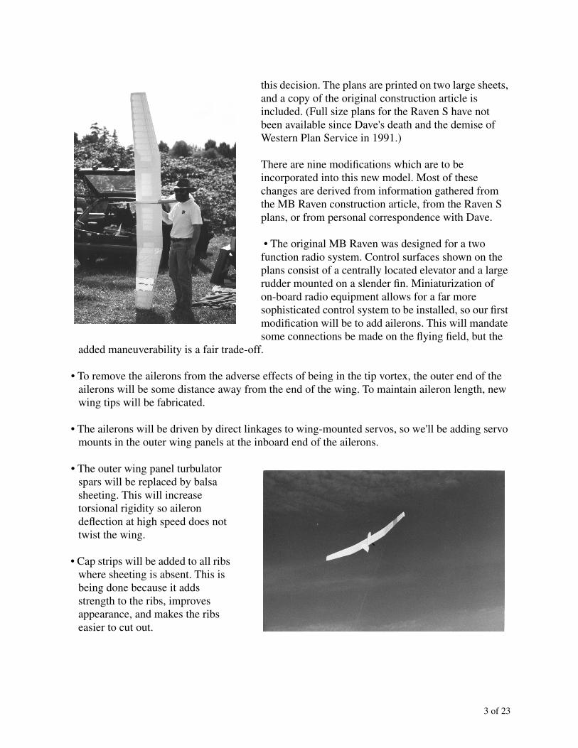
Dave Jones of Torrance California was a prolific designer of tailless aircraft. Western Plan Service, which he owned, served as the distributor of his many full size plans. His basic philosophy was that models should be relatively easy to construct, with little sanding and shaping needed, yet they should consistently perform well. The Raven series (Raven, Mini Raven, Raven 2M, Raven NFF, and Raven S) exemplified these goals. The last in the series, the Raven S, had several advanced design features, yet used simple materials and construction methods.
The Raven series was formulated to provide a competition soaring machine with different capabilities than those of conventional tailed sailplanes. All of the aircraft in the series relied on a plank planform. A reflexed airfoil section provided pitch stability. The resulting aircraft were stable wings with no sweep or twist. Because of low pitch inertia, the elevator on these models is quite powerful, despite a short lever arm. Dave designed the Raven so the center wing panel, fuselage, elevator, fin and rudder are a single unit, and all controls are permanently connected. The wing loading of these models is very low — just 4.3 oz/ft
2
for the prototype MB Raven — yet penetration in windy conditions is not a problem. Ballast can be added to bring the wing loading up to around eight oz/ft
2
.
Our first tailless model was Dave's MB Raven, which appeared as a construction article in the January 1982 issue of
Model Builder
magazine. As newcomers to the world of proportional radio equipment, we both used this model to learn to fly. In fact, we had so much fun with it that a second MB Raven, this with ballast tubes, was built a short while later. Both of these aircraft, each with several minor and a few major repairs, are still being flown.
Having already built two MB Raven, we had initially planned to build a Raven S this year. When the idea of a “build-along” construction article for
RCSD
was presented, however, we decided to delay building the Raven S and instead build a modified MB Raven. Continued availability of MB Raven full size plans from Bill Northrop’s Plans Service was the deciding factor in making

2 of 23
MODIFICATIONS TO MB RAVEN
1. add ailerons to outer panels2. add new wing tip extensions3. place aileron servos in outer wing panels4. replace turbulator spars with leading edge sheeting5. add cap strips to unsheeted portions of wings6. change polyhedral to simple dihedral7. lower dihedral angle to four degrees8. raise wing root 1/4 inch to match decking9. airfoil change from CJ-3309 to BW 05 02 09
8, 9
1
45
56, 7
2
3
6, 76, 7, 8
2
2
3 of 23
this decision. The plans are printed on two large sheets, and a copy of the original construction article is included. (Full size plans for the Raven S have not been available since Dave's death and the demise of Western Plan Service in 1991.)
There are nine modifications which are to be incorporated into this new model. Most of these changes are derived from information gathered from the MB Raven construction article, from the Raven S plans, or from personal correspondence with Dave.
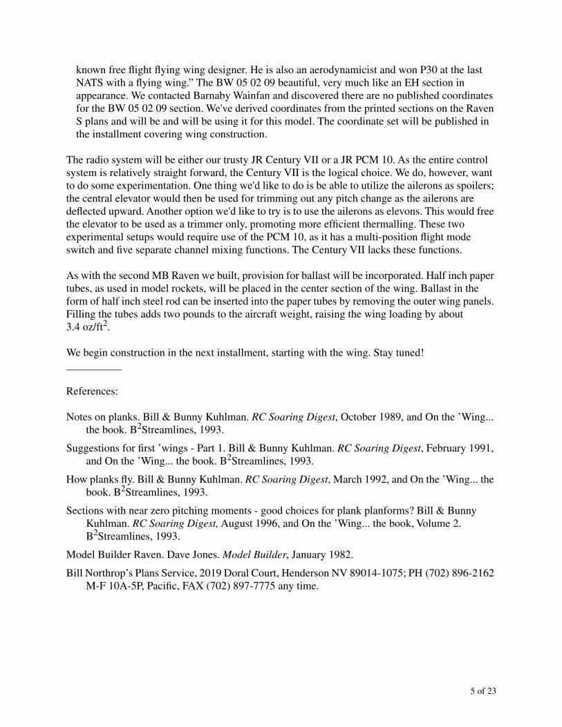
• The original MB Raven was designed for a two function radio system. Control surfaces shown on the plans consist of a centrally located elevator and a large rudder mounted on a slender fin. Miniaturization of on-board radio equipment allows for a far more sophisticated control system to be installed, so our first modification will be to add ailerons. This will mandate some connections be made on the flying field, but the
added maneuverability is a fair trade-off.
• To remove the ailerons from the adverse effects of being in the tip vortex, the outer end of the ailerons will be some distance away from the end of the wing. To maintain aileron length, new wing tips will be fabricated.
• The ailerons will be driven by direct linkages to wing-mounted servos, so we'll be adding servo mounts in the outer wing panels at the inboard end of the ailerons.
• The outer wing panel turbulator spars will be replaced by balsa sheeting. This will increase torsional rigidity so aileron deflection at high speed does not twist the wing.
• Cap strips will be added to all ribs where sheeting is absent. This is being done because it adds strength to the ribs, improves appearance, and makes the ribs easier to cut out.
4 of 23
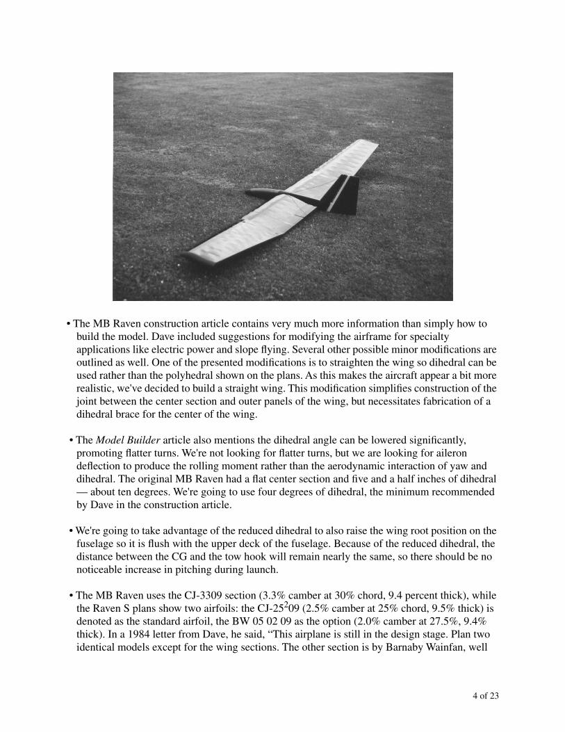
• The MB Raven construction article contains very much more information than simply how to
build the model. Dave included suggestions for modifying the airframe for specialty applications like electric power and slope flying. Several other possible minor modifications are outlined as well. One of the presented modifications is to straighten the wing so dihedral can be used rather than the polyhedral shown on the plans. As this makes the aircraft appear a bit more realistic, we've decided to build a straight wing. This modification simplifies construction of the joint between the center section and outer panels of the wing, but necessitates fabrication of a dihedral brace for the center of the wing.
• The
Model Builder
article also mentions the dihedral angle can be lowered significantly, promoting flatter turns. We're not looking for flatter turns, but we are looking for aileron deflection to produce the rolling moment rather than the aerodynamic interaction of yaw and dihedral. The original MB Raven had a flat center section and five and a half inches of dihedral — about ten degrees. We're going to use four degrees of dihedral, the minimum recommended by Dave in the construction article.
• We're going to take advantage of the reduced dihedral to also raise the wing root position on the fuselage so it is flush with the upper deck of the fuselage. Because of the reduced dihedral, the distance between the CG and the tow hook will remain nearly the same, so there should be no noticeable increase in pitching during launch.
• The MB Raven uses the CJ-3309 section (3.3% camber at 30% chord, 9.4 percent thick), while the Raven S plans show two airfoils: the CJ-25
2
09 (2.5% camber at 25% chord, 9.5% thick) is denoted as the standard airfoil, the BW 05 02 09 as the option (2.0% camber at 27.5%, 9.4% thick). In a 1984 letter from Dave, he said, “This airplane is still in the design stage. Plan two identical models except for the wing sections. The other section is by Barnaby Wainfan, well
5 of 23
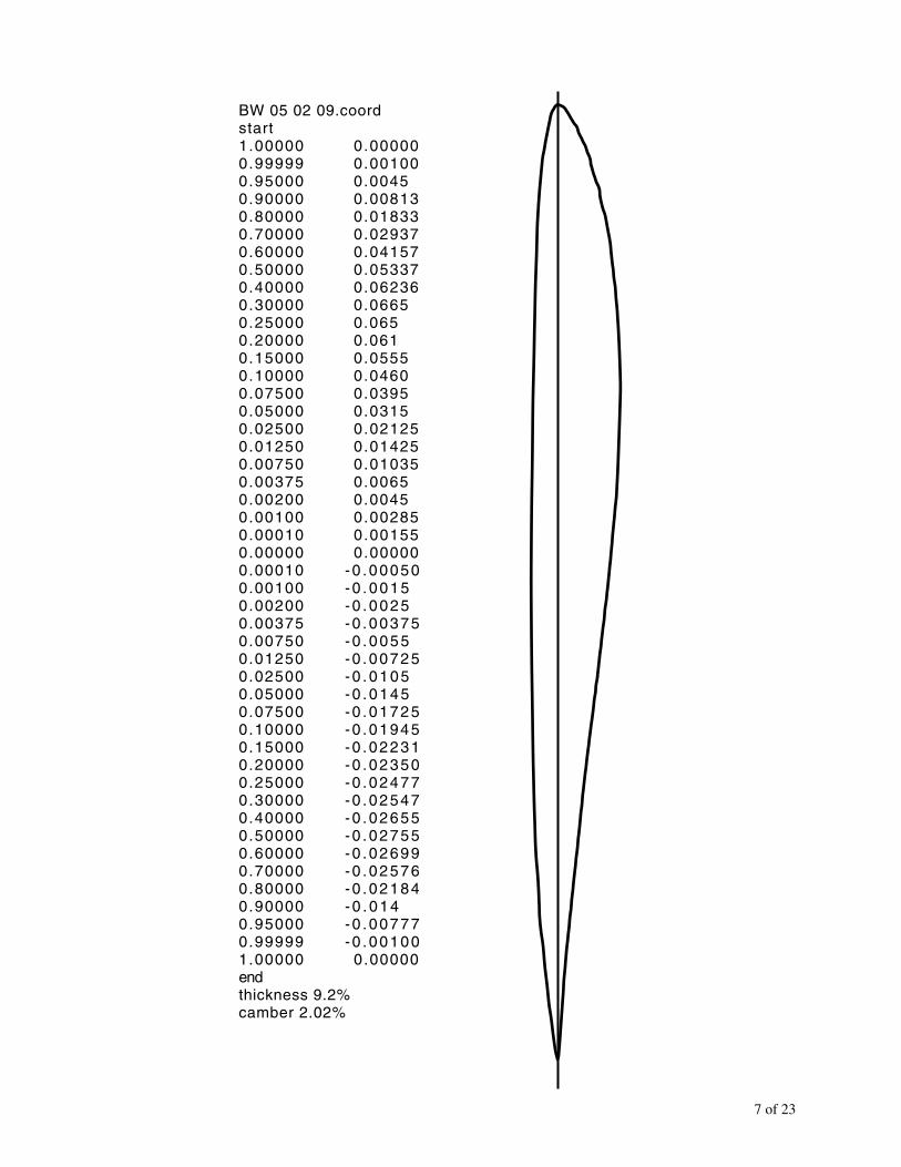
known free flight flying wing designer. He is also an aerodynamicist and won P30 at the last NATS with a flying wing.” The BW 05 02 09 beautiful, very much like an EH section in appearance. We contacted Barnaby Wainfan and discovered there are no published coordinates for the BW 05 02 09 section. We've derived coordinates from the printed sections on the Raven S plans and will be and will be using it for this model. The coordinate set will be published in the installment covering wing construction.
The radio system will be either our trusty JR Century VII or a JR PCM 10. As the entire control system is relatively straight forward, the Century VII is the logical choice. We do, however, want to do some experimentation. One thing we'd like to do is be able to utilize the ailerons as spoilers; the central elevator would then be used for trimming out any pitch change as the ailerons are deflected upward. Another option we'd like to try is to use the ailerons as elevons. This would free the elevator to be used as a trimmer only, promoting more efficient thermalling. These two experimental setups would require use of the PCM 10, as it has a multi-position flight mode switch and five separate channel mixing functions. The Century VII lacks these functions.
As with the second MB Raven we built, provision for ballast will be incorporated. Half inch paper tubes, as used in model rockets, will be placed in the center section of the wing. Ballast in the form of half inch steel rod can be inserted into the paper tubes by removing the outer wing panels. Filling the tubes adds two pounds to the aircraft weight, raising the wing loading by about 3.4 oz/ft
2
.
We begin construction in the next installment, starting with the wing. Stay tuned!__________
References:
Notes on planks. Bill & Bunny Kuhlman.
RC Soaring Digest
, October 1989, and On the ’Wing... the book. B
2
Streamlines, 1993.
Suggestions for first ’wings - Part 1. Bill & Bunny Kuhlman.
RC Soaring Digest
, February 1991, and On the ’Wing... the book. B
2
Streamlines, 1993.
How planks fly. Bill & Bunny Kuhlman.
RC Soaring Digest
, March 1992, and On the ’Wing... the book. B
2
Streamlines, 1993.
Sections with near zero pitching moments - good choices for plank planforms? Bill & Bunny Kuhlman.
RC Soaring Digest,
August 1996, and On the ’Wing... the book, Volume 2. B
2
Streamlines, 1993.
Model Builder Raven. Dave Jones.
Model Builder
, January 1982.
Bill Northrop’s Plans Service, 2019 Doral Court, Henderson NV 89014-1075; PH (702) 896-2162 M-F 10A-5P, Pacific, FAX (702) 897-7775 any time.

6 of 23
On the ’Wing... # 129
Modifying and Building the Model Builder RavenPart 2 - Constructing the Wing
We like to begin construction of any airframe with the wing. There are a couple of psychological reasons for this. The wing usually has many more pieces than any other major part of the airframe, yet wings are perceived to build faster than real time. This may be because the skeleton looks to be a lot more than it really is - sort of like framing a house. But the biggest reason for building the wing first is (with apologies to TWITT) “The wing is the thing!”
After the preliminary decisions were made, and before actual construction commenced, we once again looked at the plans in detail. We wanted to make sure all potential problems could be resolved before construction progressed to the point where solutions would be forced upon us. One significant change to construction was a switch back to wing jigs made of balsa blocks and trailing edge stock. Despite having sufficient foam on hand, the utter simplicity of using scrap balsa was just too enticing.
Formal construction of the wing began with fabrication of the rib templates. The Raven S plans gave us a detailed drawing of Barnaby Wainfan's BW 05 02 09 airfoil. We scanned the drawing and then erased all of the extraneous lines, leaving only the section profile. The resulting TIFF image was then imported into Foil 1.2, and that application did a good job of deriving a coordinate set from the digital image. MacFoil was then used to generate a large on-screen image, and the coordinates were modified until the resulting profile was smooth and MacFoil prints of the section matched the image on the plans. The resulting coordinate set is included in this column, along with a print of the section profile.
MacFoil was then used to generate profiles with 1/16" allowance for sheeting and cap strips. These paper plots were glued to aluminum flashing material using a spray adhesive, and the rib templates were then cut out. Since MacFoil also printed out percent chord marks on each plot, locating the spar caps and control surface hinge points was relatively easy. Sharp #11 X-Acto blades made relatively quick work of the wing ribs and the partial ribs required for the ends of the elevator and ailerons. Eight of the sixteen center section ribs were drilled to hold the 1/2" inside diameter paper rocket body tubes used for ballast. (See the Photo 1.)
The wing was constructed in three parts - a center section and two outer wing panels. All three major parts were constructed in the same basic order. The bottom spar cap was pinned to the work surface and the two end ribs were pinned in place using machinist blocks to assure proper alignment. The 1/4" square leading edge stock was then blocked into place using a 45 degree triangle and the pre-cut notch in the rib leading edge. With the wing jigs in place, most of the ribs were glued into position. A 1/16" plywood plate seals the end of each ballast tube. Once these plates were glued in, the ballast tubes were pushed into place and glued securely. The remaining ribs were then glued into place. Balsa sheet spar webbing was installed using a plywood and spruce template to position the webbing relative to the lower spar cap. The upper spar cap was then glued in place.
7 of 23
BW 05 02 09.coordstart1.00000 0.000000.99999 0.001000.95000 0.00450.90000 0.008130.80000 0.018330.70000 0.029370.60000 0.041570.50000 0.053370.40000 0.062360.30000 0.06650.25000 0.0650.20000 0.0610.15000 0.05550.10000 0.04600.07500 0.03950.05000 0.03150.02500 0.021250.01250 0.014250.00750 0.010350.00375 0.00650.00200 0.00450.00100 0.002850.00010 0.001550.00000 0.000000.00010 -0 .000500.00100 -0 .00150.00200 -0 .00250.00375 -0 .003750.00750 -0 .00550.01250 -0 .007250.02500 -0 .01050.05000 -0 .01450.07500 -0 .017250.10000 -0 .019450.15000 -0 .022310.20000 -0 .023500.25000 -0 .024770.30000 -0 .025470.40000 -0 .026550.50000 -0 .027550.60000 -0 .026990.70000 -0 .025760.80000 -0 .021840.90000 -0 .0140.95000 -0 .007770.99999 -0 .001001.00000 0.00000endthickness 9.2%camber 2.02%

8 of 23
The ailerons on this model are rather large, so standard JR 101 servos with ball bearing inserts, one in each outer wing panel, are used to drive them. Plywood was used to provide a mounting surface for the aileron servo and to strengthen the rib in the area of the cutout. See Figure 1. Some portions of the wing top surface required sheeting so that the aileron push rods would go through slots in solid material rather than through covering alone. Servo leads were routed through the wing such that a connection is made at the wing disassembly joint.
The dihedral braces for the outer part of the wing are different than what is shown on the plans, as there is no longer a bend in the wing at that point. Also, since the outer panel now has D-tube sheeting and cap strips, the height of the outboard section of the dihedral brace is less than that of the original. The new dihedral braces retain parallel top and bottom edges over the portion which fits into the center panel, while the portion which fits into the outer panel has a very slight taper. See Figure 2.
Simple dihedral dictates the addition of plywood bracing in the center of the wing. A straight wing with tips raised 2.5" gives 2.5 degrees of dihedral. We be made two 1/8" plywood dihedral braces for the wing center section. The brace at the front of the spar goes across one rib bay on each side, the rear brace goes across two bays on each side. There is also a sub spar dihedral brace at the elevator hinge line. See Figure 3.
The original MB Raven, which has a flat center section, maintains control linkage to the elevator even when the aircraft is disassembled for transport. We wanted to keep this positive feature, but, since we had settled on simple dihedral, the simple spruce joiner which connects the two elevator halves could not be used. We looked through our boxes of hardware and found nothing which provided an ingenious solution. One of the limiting factors is the narrow width of the rear fuselage. We finally decided to use one control horn for each elevator side, a single servo and a split pushrod. This is often done on pattern 'ships, so we're sure it will work for the Raven.
NOTE TAPER
ORIGINAL
MODIFIED
Figure 2
NOTE TAPER
OUTER PANEL DIHEDRAL BRACE

9 of 23
The original servo to elevator connection was “pull for up.” This placed the elevator control horn adjacent to the top deck. Moving the wing higher on the fuselage eliminates even this small amount of clearance, so we'll be using a “push for up” connection with the control horns on the bottom of the elevator.
Allowance also had to be made for the aileron hinging, not at all part of the original design. We used 3/32" sheet for the sub spar at the trailing edge of the wing, and the leading edge of the aileron. This is similar to the elevator structure. For lightness, the ailerons use 1/16" balsa sheeting to form a C-tube at the leading edge, plus cap strips. The entire trailing edge of the wing has a 1/2" wide strip of 1/64" plywood where the upper and lower surface sheeting meets. This allows the trailing edge to be finished to a sharp edge. While the elevator is hinged from the top, the ailerons are hinged from the bottom. This has proven an effective way to eliminate adverse yaw due to aileron deflection. See Figure 1.
The wing tip extensions were constructed of 1/16" sheet balsa. We used the arc function of our desktop publishing software (FrameMaker®) to create the elliptical curve. Figure 4 provides the shape superimposed over a grid for easy duplication. Because of the upper and lower surface curves, and the angle at which the two sheets meet along the outer edge, this structure is both light and strong.
A note on the Raven wing construction is in order, as it directly affects final assembly. As can be seen from the plans and has been mentioned previously, the wing is composed of a center section and two outer panels. During initial construction, the center panel is made 48 inches long. The
ANTERIOR CENTER PANEL DIHEDRAL BRACE
Figure 3
POSTERIOR CENTER PANEL DIHEDRAL BRACE
CENTER PANEL SUB SPAR DIHEDRAL BRACE

10 of 23
wing tips are built separately. Once complete, a wing tip is slid onto its dihedral brace and glued in place. The center panel is then cut six inches inboard of the resulting joint line, where two ribs have been placed directly adjacent to each other and the brass wing rod receptacles have been pre-installed. This construction method assures accurate alignment of the wing rod receptacles and mating of the wing surfaces. The shortened center panel (36" span) and fuselage, complete with elevator and rudder servos and linkages, form one major piece. The two outer panels complete the three piece breakdown for easy transport. See Photos 2 and 3.
The last thing to be done is to cut the elevator and ailerons free of the main wing components. This is easily done with a razor saw, but some amount of concentration is required. A few minutes with a sanding block finishes off the wing framework, and it's now ready for covering.
Some parts of the wing construction were delayed because we lacked the ballast tubes. Your local hobby shop can order these either directly from Estes or from a wholesaler, but it's
SERVO
1/16¨ PLYWOODAILERON
1/64¨ PLYWOOD
MONOKOTE HINGEFigure 1
WING TIP EXTENSION
Figure 4
1/2¨ SQUARES

11 of 23
Bottom of the wing, before the sheeting is glued on, showing the installation of theballast half inch “rocket” tubes. When steel inserts are used, the weight increases
by 32 oz and the wing loading rises from 4.3 to 7.7 oz/sq ft
2
.
Completed three part Raven wing. The center panel will be epoxied to the fuselage.

12 of 23
helpful if you have a description and part number and order these ahead of time. Relevant information has been included at the end of this column.
We'd like to recommend Superior Balsa and Hobby Supply, Hawaiian Gardens California, as a source for balsa, plywood, music wire and brass tubing, and other items needed for construction. We've ordered from a number of balsa suppliers over the years, and have found Superior to indeed live up to their name. The prices are more than reasonable, and we've never seen better wood. The balsa is light weight but not at all spongy, the grain is straight with no aberrations, and everything is cut true. If you've not ordered from Superior before, please give them a try.
The plan set available from Bill Northrop's Plan Service includes a copy of the magazine construction article. If you have specific questions about construction of the modified MB Raven, please contact us at either P.O. Box 975, Olalla WA 98359 or by e-mail at <[email protected]>.
Next installment: Building the fuselage, fin and rudder.
__________
References and sources:
Aileron differential, Part 1. Bill & Bunny Kuhlman.
RC Soaring Digest
, May 1996, and On the ’Wing... the book, Volume 2. B
2
Streamlines, 1998.
Bill Northrop’s Plans Service, 2019 Doral Court, Henderson NV 89014-1075; PH (702) 896-2162 M-F 10A-5P, Pacific, FAX (702) 897-7775 any time.
Estes Industries, 1295 H Street, Penrose CO 81240. Rocket body tubes, BT-5, 0.544" ID, four 18" lengths per package, part number EST 303084, about $6.00.
Foil 1.2 by Gregory Payne, <[email protected]>. Available at the Foil 1.2 web site, <http://members.aol.com/kgpayne/foil.html>.
FrameMaker® is a product of Adobe Systems Inc., 1585 Charleston Rd, P.O. Box 7900, Mountain View CA 94039-7900. FrameMaker® information is available at the Adobe web site, <http://www.adobe.com>
MacFoil by Dave Johnson, 58 Chenery St, San Francisco CA 94131 and <[email protected]>. Available at the MacFoil web site, <www.sirius.com/~djohnson/macfoil.html>.
Model Builder Raven. Dave Jones.
Model Builder
, January 1982.
Personal correspondence, Barnaby Wainfan.
Superior Balsa and Hobby Supply, 12020-G Centralia, Hawaiian Gardens CA 90716. (800) 488-9525, Monday through Saturday, 7 AM - 7 PM. On the web at <www.superiorbalsa.com> and <[email protected]>.

13 of 23
On the ’Wing... # 130
Modifying and Building the Model Builder RavenPart 3 — Constructing the Fuselage, Fin and Rudder
With the wing framed, the majority of the MB Raven construction is complete. This month we tackle the fuselage, fin and rudder.
For those accustomed to tailed aircraft, the MB Raven fuselage appears truncated. Despite the appearance, the fuselage is streamlined. It’s also easily built and incredibly strong. The short overall length is actually an advantage, as its contribution to inertia in pitch and yaw is exceptionally low. The recess in the bottom of the fuselage places the tow hook very close to the CG, so there is little leverage to drive the wing upward in pitch during winch launches.
Because we raised the wing to make its upper surface flush with the top deck of the fuselage, the template for the fuselage sides is different than what appears on the plans. The discrepancies are not much, but they are noticeable. The fuselage is a bit deeper beneath the wing and the wing saddle is of a different contour, the upper decking must follow the upper surface of the airfoil, and the former at the rear of the canopy must be moved a fraction of an inch forward to clear the leading edge of the wing.
As with the wing ribs, we used aluminum flashing material to create the templates for the fuselage sides. All interior fuselage parts — oak nose block, balsa formers and compression blocks — were fabricated with a table saw, radial arm saw, and sanding bars. Machinist squares were used throughout construction to assure the fuselage sides were always aligned and vertical.
As mentioned in our column last month, the servo to elevator connection for this version of the MB Raven is somewhat problematic. The elevator is in two parts, and each side is driven by its own control horn. We cut
1
/
16
" plywood control horns to the outline indicated on the plans, then notched them so they fit below the elevator rather than above. A small length of brass tubing serves as a bearing for the clevis pin.
Installation of servos in the fuselage is easy as there is no tray, just rails. Due to the wing being higher on the fuselage, all of the pushrods are placed below the wing rather than curving over it. For this MB Raven, the receiver was moved forward to a position directly behind the battery. The servos are behind the receiver and in front of the leading edge of the wing, mounted at a sloping angle downward toward the fuselage rear. We exchanged the locations of the rudder and elevator servos in order to eliminate an unnecessary curve in the rudder cable. Mounting the rudder servo on the left side allows the cable to traverse the full width of the fuselage and have a relatively straight path to the rudder control horn which stays on the right side. The elevator hook-up utilizes a pushrod and so is very straight forward.
The elevator pushrod assembly must be connected to the control horns prior to mounting the wing on the fuselage, as all connections are on the under side of the wing. We used separate pushrods for each elevator half. A copper wire wrapped solder joint permanently connects the two pushrods to a single connection with the servo arm. Former 6, a compression block which also serves to

14 of 23
join the plywood and balsa body sides, had to be carved out to clear the elevator pushrods and serve as a support for the rudder pushrod conduit. The elevators were temporarily attached to the wing using masking tape while all of the connections were fabricated. (MonoKote® hinges will be installed during the covering process.)
The canopy is cut and formed to match the fuselage framing and to feather into the top deck. The canopy cross-section is a semi-circle. We follow Dave Jones admonition and always tape the canopy in place, so there are no fancy internal latching mechanisms.
We fabricated several concave sanding blocks to assist in shaping the fuselage bottom and canopy areas. We used a Forstner bit and a drill press to cut a hole in a scrap 2x4, then ran the table saw blade so the edge of the kerf crossed the center of the hole. A mixture of five minute epoxy and microballoons was used to join the sandpaper to the inside of the cutout. The first, 2
1
/
4
" in diameter, was used to shape the canopy once we had planed and rough sanded the outline. Such sanding blocks are very easy to construct, so we made several more, each
1
/
4
" smaller in diameter. The smallest has a diameter of
1
/
2
", to be used for shaping the leading edge of the fin.
The aileron servo cables exit the wing at the center of the top surface, right behind the spruce leading edge and rear canopy frame. From there they go down the fuselage sides, below the rudder and elevator servos, to the receiver. We seldom do anything within the fuselage cavity except change battery packs, so this additional wiring is not in the way.
Because of the assembly schedule, we started construction of the fin and rudder before the fuselage was complete. The vertical fin and rudder are lightweight structures with quite a bit of cross-bracing to prevent the covering from wrinkling. The fin is essentially a flat plate airfoil of narrow chord with a rounded leading edge. The rudder is large, and due to its shape it must be built using a piece of trailing edge stock as a jig.
1.25"
5"
TEMPLATE FOR FIN AND RUDDER CONTOUR (
1
/
4
" squares)

15 of 23
LEFT: Completed fin and rudder framework. Diagonals and gussets give torsional strength. The covering applies easily to this framework.
BELOW RIGHT: Side view of the fuselage and center wing panel assembly. The fuselage takes some work to get the proper contour, but a set of templates assures symmetry and fluid lines.
BELOW LEFT: View from the left front shows how the fuselage top joins the upper wing surface.

16 of 23
The completed Raven airframe, ready for covering.
To match the added wing tip extensions, we constructed the upper portion of the fin by laminating
1
/
16
" x
1
/
2
" balsa sheet around a scrap pine form. The combined fin and rudder area remains the same as on the plans. The FrameMaker® arc function produced a very nice elliptical template for this purpose, and we’ve included it here on a
1
/
4
" grid for easy duplication. The top of the rudder is a piece of
1
/
4
" sheet. The leading edge of the fin was sanded to a semi-circle cross-section with a
1
/
4
" radius concave sanding block. The laminated curve of the fin was sanded to this shape as well. The top of the rudder was then sanded to match the extension template contour and the
1
/
4
" radius of the leading edge, with a smooth transition to the trailing edge.
The wing is mounted to the fuselage by epoxying the wing to the two compression blocks and the wing saddle. This joint, since it has such a large surface, is strong enough to withstand winch launches without pulling the fuselage from the wing. Once the wing was in place, a balsa block was shaped to transition from the rear of the canopy to the high point of the wing, and a piece of
1
/
8
" sheet decking was fitted to transition from the high point of the wing back along the base of the fin.
An Airtronics adjustable tow hook was installed as called for on the plans. This lightweight assembly consists of an aluminum alloy channel through which a small nut passes, and the tow hook has a nut placed on its threaded section. The tow hook is screwed into the nut in the channel and then locked in position anywhere along the length of the channel by using the second nut to tighten the assembly. We’ve replaced the original hook with a piece of
1
/
8
" music wire, bent to a 90 degree angle and threaded with a 4-40 die. A 4-40 nut must be filed down in thickness and width to fit in the channel, but the resulting installation is more than strong enough to take full power winch launches without bending. Unfortunately, Airtronics no longer produces this item, and we have been unable to find a matching extrusion.
We tackle covering and flying in the next installment.

17 of 23
The plan set available from Bill Northrop's Plan Service includes a copy of the magazine construction article. If you have specific questions about construction of the modified MB Raven, please contact us at either P.O. Box 975, Olalla WA 98359 or by e-mail at <[email protected]>.__________
References and sources:
Bill Northrop’s Plans Service, 2019 Doral Court, Henderson NV 89014-1075; PH (702) 896-2162 M-F 10A-5P, Pacific, FAX (702) 897-7775 any time.
FrameMaker® is a product of Adobe Systems Inc., 1585 Charleston Rd., P.O. Box 7900, Mountain View CA 94039-7900. FrameMaker® information is available at the Adobe web site, <http://www.adobe.com>
Model Builder Raven. Dave Jones.
Model Builder
, January 1982.
Superior Balsa and Hobby Supply, 12020-G Centralia, Hawaiian Gardens CA 90716. (800) 488-9525, Monday through Saturday, 7 AM - 7 PM. On the internet at <www.superiorbalsa.com> and <[email protected]>.

18 of 23
On the ’Wing... # 131
Modifying and Building the Model Builder RavenPart 4 — Covering and Flying
As is usual when modifying an airplane, a couple of minor difficulties have reared their ugly heads during construction.
The first of these monsters made itself known after we thought the wing was complete. We found the ailerons twisted a bit too easily. Given their length and size, we anticipated that the covering material would not add sufficient strength. Our solution was to add a
1
/
16
" diagonal rib between each pair of existing ribs. This was a tricky proposition, as we did not want to build new ailerons or tear apart the existing set, but we did manage to install them successfully. These diagonal ribs have cap strips installed.
A second problem involved the elevator control horns and the upper fuselage decking. Since the wing was raised relative to the fuselage, the clearance between the elevator control horn and the
1
/
8
" upper decking is very small. We had to cut down the control horn mounting lugs and make a rectangular hole in the decking. Once we were assured that there was sufficient up elevator travel, we sealed off the hole with a piece of
1
/
64
" plywood. After some judicious sanding, the surface discontinuity is barely noticeable.
After much thought, we settled on covering the wing with transparent MonoKote®. Two of the four 6' rolls we purchased were defective. Replacement covering was extremely slow in coming from Great Planes, so we ordered additional MonoKote® from a local source, Hobby Town in Parkland Washington. Jon Packer, the manager of Hobby Town, had special ordered the
1
/
2
" rocket body tubes for us, so we relied on him to solve this problem as well. Jon had the covering in stock, checked it for defects before mailing it out, and we got it in the mail the next day. Thanks Jon!
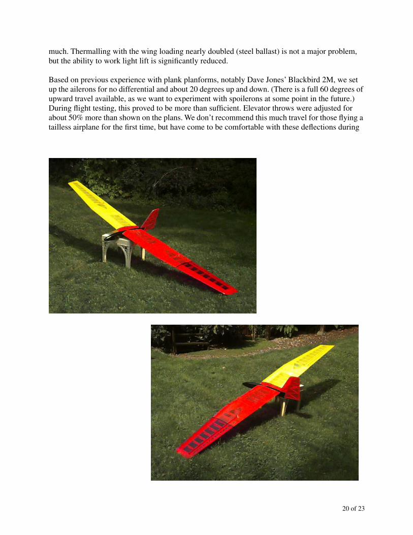
From the left wingtip to a point 24" inboard is transparent red; the next 36" is covered with transparent orange; the remaining 57" is transparent yellow. Aileron and elevator hinges were formed using the MonoKote® covering. A
3
/
8
" wide black trim stripe separates each color. The vertical fin and rudder are covered with transparent orange MonoKote®. We used four Klett
54"36"24"

19 of 23
hinges we had in our parts box. The fuselage and canopy were first sprayed with gray primer, then gloss black.
With leading edge sheeting, ailerons, two extra servos and cabling, three ounces of nose weight, and a five cell receiver battery, the weight of our model compares favorably with the prototype MB Raven built by Dave Jones. That prototype MB Raven, built using “contest” balsa, weighed just 41 ounces and had a wing loading of 4.3 oz/ft
2
. Our Raven weighs 60 ounces. With its slightly larger area, the wing loading is just over six oz/ft
2
.
As mentioned in a previous installment, ballast can be added by means of inserting metal rods into the four nine inch paper rocket tubes in the center section of the wing. Half inch diameter metal rod is used as ballast. A 36" aluminum rod weighs 12 ounces and raises the wing loading approximately 1.2 oz/ft
2
. Steel rod adds almost exactly two pounds to the overall weight of the glider, and raises the wing loading by 3.2 oz/ft
2
. We cut both rods into three inch sections with an abrasion wheel mounted in our table saw. The three inch length makes the ballast easier to carry around — we have a small padded case for this purpose — and allows combinations to be used (12, 18.6, 25.3 and 32 additional ounces). See the included graph.
Since the ballast is placed somewhat outboard of the centerline, inertia in roll and yaw is increased. This is actually helpful in gusty weather as the glider does not bounce around quite so
12 32
4
6
8
none
aluminum
steel
0
BALLAST, OUNCES
WIN
G L
OA
DIN
G, O
Z/F
T
2
20 of 23
much. Thermalling with the wing loading nearly doubled (steel ballast) is not a major problem, but the ability to work light lift is significantly reduced.
Based on previous experience with plank planforms, notably Dave Jones’ Blackbird 2M, we set up the ailerons for no differential and about 20 degrees up and down. (There is a full 60 degrees of upward travel available, as we want to experiment with spoilerons at some point in the future.) During flight testing, this proved to be more than sufficient. Elevator throws were adjusted for about 50% more than shown on the plans. We don’t recommend this much travel for those flying a tailless airplane for the first time, but have come to be comfortable with these deflections during
21 of 23
more than 15 years of flying this design. Rudder throw is 20 degrees each way, as recommended in the construction article.
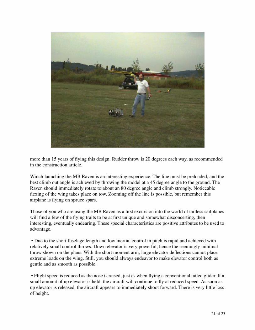
Winch launching the MB Raven is an interesting experience. The line must be preloaded, and the best climb out angle is achieved by throwing the model at a 45 degree angle to the ground. The Raven should immediately rotate to about an 80 degree angle and climb strongly. Noticeable flexing of the wing takes place on tow. Zooming off the line is possible, but remember this airplane is flying on spruce spars.
Those of you who are using the MB Raven as a first excursion into the world of tailless sailplanes will find a few of the flying traits to be at first unique and somewhat disconcerting, then interesting, eventually endearing. These special characteristics are positive attributes to be used to advantage.
• Due to the short fuselage length and low inertia, control in pitch is rapid and achieved with relatively small control throws. Down elevator is very powerful, hence the seemingly minimal throw shown on the plans. With the short moment arm, large elevator deflections cannot place extreme loads on the wing. Still, you should always endeavor to make elevator control both as gentle and as smooth as possible.
• Flight speed is reduced as the nose is raised, just as when flying a conventional tailed glider. If a small amount of up elevator is held, the aircraft will continue to fly at reduced speed. As soon as up elevator is released, the aircraft appears to immediately shoot forward. There is very little loss of height.

22 of 23
• Due to the low inertia in pitch, recovery from a stall is rapid as well. Acceleration to flight speed and transition to level flight, even with the aircraft at a standstill in a nose vertical attitude, takes but a few feet of height. Once speed is above minimum, judicious use of up elevator can make recovery even more rapid. With practice, you can make a tight half loop using full up elevator with the aircraft coming to a complete stop just as it is inverted and at the peak of the loop. (The entry speed is critical.) Release up elevator while the aircraft is stopped. The Raven will quickly rotate to a nose down attitude, then accelerate through a large arc and transition to upright gliding flight in the same direction as at the start. The resulting maneuver traces the outline of a comma.
• If you’ve built the MB Raven according to the plans and without ailerons, you’ll find that it turns much quicker if up elevator is applied before rudder control is input. Depending on how elevator and rudder are coordinated, flat or steeply banked turns can be made.
• Although the MB Raven may fall off onto one wing if fully stalled while in a turn, we’ve not been able to enter a spin.
• Thermalling is as easy as finding lift, setting the turn, and putting in some up trim. The Raven signals lift by pitching up. This motion is sometimes quite dramatic, and the airplane slows as it travels through the thermal. Centering is nearly automatic.
• The MB Raven does exceptionally well in light lift if the overall weight is kept down. At a recent contest, Bill twice set up his R/E Raven for a landing well short of the desired flight time. Both times, the Raven flew through a patch of very light lift on final approach, and was immediately turned back into the rising air. A series of flat turns in the low altitude thermal allowed the flight times to be met. Moral: Don’t give up until you’re on the ground.
The MB Raven offers a unique, but certainly not terrifying, flying experience. We will no doubt enjoy this newest addition to our aerie for many years to come and hope the same is true for you.

23 of 23
We are genuinely interested in hearing from
RCSD
readers who have built a MB Raven due to this four part series. We can be reached at P.O. Box 975, Olalla WA 98359-0975, or at <[email protected]>.__________
References and sources:
Bill Northrop’s Plans Service, 2019 Doral Court, Henderson NV 89014-1075; PH (702) 896-2162 M-F 10A-5P, Pacific, FAX (702) 897-7775 any time.
Hobby Town, Jon Packer Manager, 402 Garfield St, Tacoma, WA 98444; (253) 531-8111.
Model Builder Raven. Dave Jones.
Model Builder
, January 1982.
Recommendations for first tailless, Part 1. Bill & Bunny Kuhlman.
RC Soaring Digest
, February1991, and On the ’Wing... the book. B
2
Streamlines, 1993.
Differential and performance. Bill & Bunny Kuhlman.
RC Soaring Digest
, August 1992, and On the ’Wing... the book. B
2
Streamlines, 1993.
Aileron differential, Part 1. Bill & Bunny Kuhlman.
RC Soaring Digest
, May 1996, and On the ’Wing... the book, Volume 2. B
2
Streamlines, 1998.