modernisation of a lignite-fired steam generator ... · modernisation of a lignite-fired steam...
TRANSCRIPT

Modernisation of a lignite-fired steam generator – Reduction of NOx emissions
By Ralf Kriegeskotte, Quinto Di Ferdinando, Hans-Ulrich Thierbach and Bernhard Zimmermann
Vo lu me 93 – Is sue 10/2013 Page 47 to 50


3
VGB PowerTech 10 l 2013 Revamping of lignite boiler with less NOx emissions
Authors
Kurzfassung
Modernisierung eines braunkohle-gefeuerten Dampferzeugers – Reduzierung der NOx-Emissionen
ContourGlobal Maritsa East 3 ist ein mit Braunkohle befeuertes Kraftwerk mit einer installierten elektrischen Leistung von 4 x 227 MWel. Die 4 Dampferzeuger russischer Bauart mit einer Dampfleistung bis 730 t/h wurden in den Jahren 1978 bis 1981 in Betrieb genommen.Um den Betrieb des Kraftwerks langfristig si-cherzustellen, müssen die NOx-Emissionswerte von bis zu 400 mg/Nm3 sicher unter den künf-tigen gesetzlichen Grenzwert von 200 mg/Nm3 (jeweils bezogen auf 6 % O2, trocken) bis Ende 2015 reduziert werden (EU-Richtlinie 2010/75/EU für Industrieemissionen).Das Konsortium Steinmüller Engineering GmbH, Gummersbach und Siemens EOOD, Sofia, beide Firmen gehörend zum Siemens Konzern, hat im Auftrag des Kraftwerkseigen-tümers und -betreibers, ContourGlobal Maritsa East 3 AD, Sofia, den erfolgreichen Umbau der Feuerung der Kesselanlage 4 dieses Kraftwerkes durchgeführt.Wesentliche Herausforderungen stellten die sehr kompakte Kesselgeometrie mit vergleichs-weise kurzen Verweilzeiten und die Qualität der bulgarischen Braunkohle dar. Charakteris-tisch für die Kohle sind ein Heizwert von 6 bis 7 MJ/kg, ein Wassergehalt von 50 bis 60 %, ein Aschegehalt im Bereich von 10 bis 20 % sowie ein sehr kritisches Verschlackungsverhalten. Steinmüller Engineering entwickelte und rea-lisierte ein Modernisierungskonzept, welches als Resultat eine umfassende Lösung für die technisch komplexe und außerdem terminlich extrem anspruchsvolle Aufgabenstellung des Kraftwerksbetreibers liefert. Nach dem Umbau steht diesem ein Kraftwerksblock zur Verfü-gung, der umweltfreundlicher, zuverlässiger und zudem effizienter und somit wirtschaft-licher die lokale Braunkohle verstromt. l
Modernisation of a lignite-fired steam generator – Reduction of NOx emissionsRalf Kriegeskotte, Quinto Di Ferdinando, Hans-Ulrich Thierbach and Bernhard Zimmermann
Ralf KriegeskotteSteinmüller Engineering GmbH Gummersbach/GermanyQuinto Di FerdinandoContourGlobal Maritsa East 3 AD Sofia/BulgariaDr. Hans-Ulrich ThierbachDr. Bernhard ZimmermannSteinmüller Engineering GmbH Gummersbach/Germany
Introduction and description of task
Situation prior to revamping the firing systemContourGlobal Maritsa East 3 thermal power plant with a capacity of 4 x 227 MWel is one of the largest power plants in Bulgaria. It is located next to the coal mines of Maritsa East, in the South East of the city of Stara Zagora and close to the town of Galabovo. These coal mines provide the power plant with lignite, which has very high moisture, sulphur and ash content and a comparatively low calorific value (Ta b l e 1). At the same time, this lignite tends to a critical slagging behaviour in the furnace, which had to be considered thor-oughly during project execution.The 4 steam generators were built by the Podolsk Boiler Works in Russia and com-missioned between the years 1978 and 1981. After privatisation of the power plant at the beginning of this century, a substan-tial rehabilitation took place between 2003 and 2009, which allows coping with all currently existing environmental require-ments.With respect to the further environmental requirements for the power plant to reduce NOx emissions below 200 mg/Nm3 (at 6 % O2, dry gas), ContourGlobal decided to have the existing firing system again re-vamped extensively in order to meet those requirements by primary measures.
Technical objectives for the projectThe technical requirements and objectives for this project can be summarised as fol-lows:
– Reduction of the NOx emissions from approximately 400 mg/Nm3 to below 180 mg/Nm3 at 6 % O2, dry gas,
– Efficiency increase of the furnace by re-duction of the excess air ratio from 1.2 to 1.15 (at furnace outlet),
– Keeping the CO emissions below 180 mg/Nm3 at 6 % O2, dry gas,
– Preventing the water walls from corro-sion,
– Preventing the furnace from slagging, and
– Keeping the parameters of the pressure part in the range as before revamping.
Project execution
Determination of the conceptTo achieve the above-mentioned goals and contractual obligations, a new concept for the entire firing system had to be devel-oped:
Modification of the main burnersWith the existing configuration of the coal dust burners, it was not possible to achieve the reduction of the NOx formation to the required emission levels. Therefore, a new design for the burners was developed and optimised based upon a similar design with good experiences of successfully executed projects in other utilities. A good blend-ing of the air in the gas/coal dust flow re-quires a relative high difference in speed between both flows. In this respect, the cross-sections of the secondary air at the main burner (upper, core, intermediate and lower air flow) and of the dust fingers were adjusted taking into consideration the adapted air flow to the burners. For stable firing of the coal dust/air mixture in
Tab. 1. Typical analysis for Maritsa lignite.
As received Dry-ash-free
C [%] 20.35 67.83
H [%] 1.70 5.67
O [%] 6.26 20.87
N [%] 0.36 1.20
S [%] 1.33 4.43
Water [%] 53.00 –
Ash [%] 16.97 –
Net calorific value [MJ/kg] 6.425 25.706

4
Revamping of lignite boiler with less NOx emissions VGB PowerTech 10 l 2013
the proximity of the burner outlet, flame stabilisers are used at the exits of the in-dividual coal dust fingers. The stabilisers serve to slow down part of the dust parti-cles and thus to create a turbulence of par-ticles, to speed up the release of volatiles and to stabilise the ignition close to the outlet of the burners.The arrangement and size of the core air pipes for the main burners are designed to ensure a proper mixing of pulverised fuel with the combustion air and to provide an integrated system of protection air of the furnace water wall. Hence this design will significantly decrease the slagging and corrosion risk in the burner belt area. In F i g u r e 1 the old burner and the re-vamped burner design are compared.
Installation of a new side wall and over-fire air systemIn order to protect the membrane walls against corrosion and slagging and to sup-port air staging in the furnace for efficient NOx reduction, a new side-wall-air system (SWA) located at each wall of the boiler was installed. Each wall was equipped with SWA nozzles, which create the necessary O2 atmosphere at the furnace walls.Also a new over-fire-air system located at the front and rear wall of the boiler was installed in order to inject the required re-maining air amount necessary for complete combustion of the reaction products above the top burner level at a fixed distance and high velocity. The strong impulse of this air injection creates a good penetration and mixing of the flue gas with the air and pro-
vides the required oxygen for the combus-tion of the carbon monoxide that is not yet completely converted in the burner area.The new combustion design provides an optimised residence time for the coal par-ticles in the combustion chamber by re-ducing the height of the primary burner belt zone and increasing the height of the secondary zone above the top burner level (burnout stage). This is achieved by staging the primary combustion along the vertical axis of the furnace in front of the lower burner part. This staging has a sig-nificantly positive effect on the NOx forma-tion, because the oxygen concentration and the formation of fuel NOx are closely interconnected.
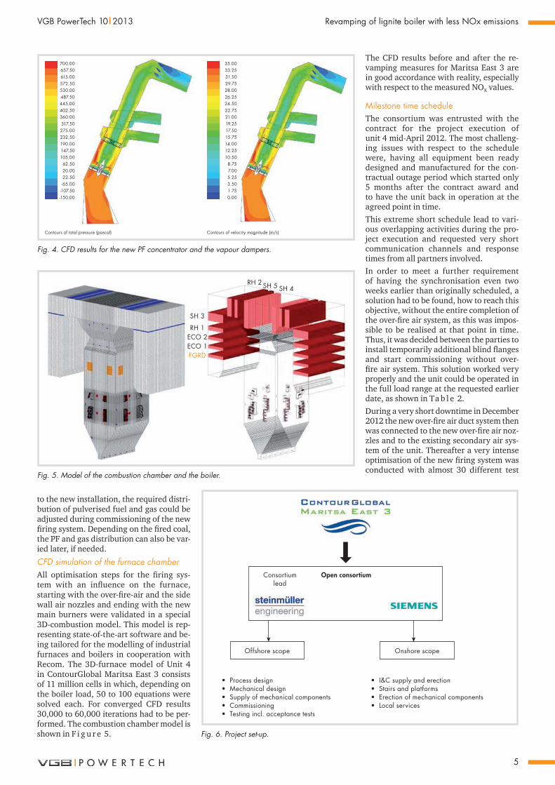
Pulverised fuel (PF) systemF i g u r e 2 shows another area of the fir-ing system, where optimisations have been realised. The respective measures were conducted at the pulverised fuel ducts tar-geting for an optimised pulverised fuel and vapor distribution for the new low-NOx fir-ing system.In order to find the optimal solution re-garding the modifications both a 3D CFD model and a physical model have been re-alised during the short engineering phase. To validate the results of the CFD-model, tests were performed in the physical flow model (scale: 1:10). The model is shown in F i g u r e 3.The results of the CFD model were in very good accordance with the physical flow model (F i g u r e 4), which gave additional safeness for the further project execution. Also the later distribution measurements on site, executed during tests in the hot commissioning stage, were in good compli-ance with the model results.With this arrangement it was possible to find the best suitable coal/vapour distribu-tion by varying the respective settings. Due
Before revamping After revamping
Fig. 1. Comparison between the old and the new burner design.
New dampers
New swirl
Fig. 2. New PF concentrator and vapour dampers.
Swirl 1
P2
P3P4
P1
230
364
Inside
1470
820
Swirl 2
Finger 1
Finger 2
Finger 3
Fig. 3. Physical model.
5
VGB PowerTech 10 l 2013 Revamping of lignite boiler with less NOx emissions
to the new installation, the required distri-bution of pulverised fuel and gas could be adjusted during commissioning of the new firing system. Depending on the fired coal, the PF and gas distribution can also be var-ied later, if needed.
CFD simulation of the furnace chamberAll optimisation steps for the firing sys-tem with an influence on the furnace, starting with the over-fire-air and the side wall air nozzles and ending with the new main burners were validated in a special 3D-combustion model. This model is rep-resenting state-of-the-art software and be-ing tailored for the modelling of industrial furnaces and boilers in cooperation with Recom. The 3D-furnace model of Unit 4 in ContourGlobal Maritsa East 3 consists of 11 million cells in which, depending on the boiler load, 50 to 100 equations were solved each. For converged CFD results 30,000 to 60,000 iterations had to be per-formed. The combustion chamber model is shown in F i g u r e 5.
700.00657.50615.00572.50530.00487.50445.00402.50360.00317.50275.00232.50190.00147.50105.0062.5020.00-22.50-65.00-107.50-150.00
35.0033.2531.5029.7528.0026.2524.5022.7521.0019.2517.5015.7514.0012.2510.50
8.757.005.253.501.750.00
Contours of total pressure (pascal) Contours of velocity magnitude (m/s)
Fig. 4. CFD results for the new PF concentrator and the vapour dampers.
RH 2 SH 5 SH 4
SH 3
RH 1ECO 2ECO 1FGRD
Fig. 5. Model of the combustion chamber and the boiler.
The CFD results before and after the re-vamping measures for Maritsa East 3 are in good accordance with reality, especially with respect to the measured NOx values.
Milestone time scheduleThe consortium was entrusted with the contract for the project execution of unit 4 mid-April 2012. The most challeng-ing issues with respect to the schedule were, having all equipment been ready designed and manufactured for the con-tractual outage period which started only 5 months after the contract award and to have the unit back in operation at the agreed point in time.This extreme short schedule lead to vari-ous overlapping activities during the pro-ject execution and requested very short communication channels and response times from all partners involved.In order to meet a further requirement of having the synchronisation even two weeks earlier than originally scheduled, a solution had to be found, how to reach this objective, without the entire completion of the over-fire air system, as this was impos-sible to be realised at that point in time. Thus, it was decided between the parties to install temporarily additional blind flanges and start commissioning without over-fire air system. This solution worked very properly and the unit could be operated in the full load range at the requested earlier date, as shown in Ta b l e 2.During a very short downtime in December 2012 the new over-fire air duct system then was connected to the new over-fire air noz-zles and to the existing secondary air sys-tem of the unit. Thereafter a very intense optimisation of the new firing system was conducted with almost 30 different test
• Process design• Mechanical design• Supply of mechanical components• Commissioning• Testing incl. acceptance tests
• I&C supply and erection• Stairs and platforms• Erection of mechanical components• Local services
Offshore scope Onshore scope
Open consortiumConsortiumlead
Fig. 6. Project set-up.
6
Revamping of lignite boiler with less NOx emissions VGB PowerTech 10 l 2013
settings having been checked in order to find the best suitable settings and to meet all targets as described above at the same time.
Project set-up
The project set-up selected for this project is an open consortium, in which Steinmül-ler Engineering is responsible for the con-sortium lead and for the so called “offshore scope”, whereas the local consortium part-ner Siemens EOOD took over the responsi-
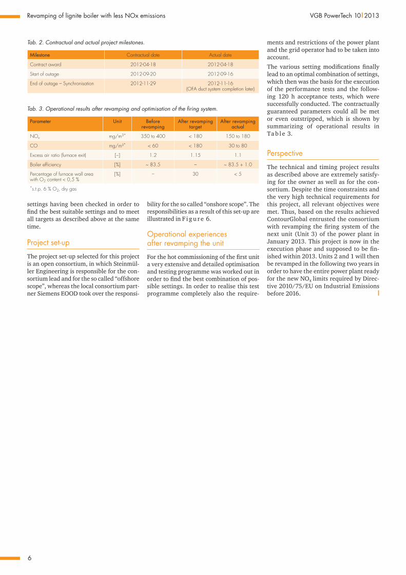
Tab. 3. Operational results after revamping and optimisation of the firing system.
Parameter Unit Before revamping
After revamping target
After revamping actual
NOx mg/m3* 350 to 400 < 180 150 to 180
CO mg/m³* < 60 < 180 30 to 80
Excess air ratio (furnace exit) [–] 1.2 1.15 1.1
Boiler efficiency [%] ~ 83.5 – ~ 83.5 + 1.0
Percentage of furnace wall area with O2 content < 0,5 %
[%] – 30 < 5
*s.t.p. 6 % O2, dry gas
Tab. 2. Contractual and actual project milestones.
Milestone Contractual date Actual date
Contract award 2012-04-18 2012-04-18
Start of outage 2012-09-20 2012-09-16
End of outage – Synchronisation 2012-11-29 2012-11-16 (OFA duct system completion later)
bility for the so called “onshore scope”. The responsibilities as a result of this set-up are illustrated in F i g u r e 6.
Operational experiences after revamping the unit
For the hot commissioning of the first unit a very extensive and detailed optimisation and testing programme was worked out in order to find the best combination of pos-sible settings. In order to realise this test programme completely also the require-
ments and restrictions of the power plant and the grid operator had to be taken into account.
The various setting modifications finally lead to an optimal combination of settings, which then was the basis for the execution of the performance tests and the follow-ing 120 h acceptance tests, which were successfully conducted. The contractually guaranteed parameters could all be met or even outstripped, which is shown by summarizing of operational results in Ta b l e 3.
Perspective
The technical and timing project results as described above are extremely satisfy-ing for the owner as well as for the con-sortium. Despite the time constraints and the very high technical requirements for this project, all relevant objectives were met. Thus, based on the results achieved ContourGlobal entrusted the consortium with revamping the firing system of the next unit (Unit 3) of the power plant in January 2013. This project is now in the execution phase and supposed to be fin-ished within 2013. Units 2 and 1 will then be revamped in the following two years in order to have the entire power plant ready for the new NOx limits required by Direc-tive 2010/75/EU on Industrial Emissions before 2016. l