modern introductory physics ||
TRANSCRIPT


Modern Introductory Physics


Charles H. Holbrow • James N. LloydJoseph C. Amato • Enrique GalvezM. Elizabeth Parks
Modern Introductory Physics
Second Edition
123

ISBN 978-0-387-79079-4 e-ISBN 978-0-387-79080-0DOI 10.1007/978-0-387-79080-0Springer New York Dordrecht Heidelberg London
Library of Congress Control Number: 2010930691
c© Springer Science+Business Media, LLC 1999, 2010All rights reserved. This work may not be translated or copied in whole or in part without thewritten permission of the publisher (Springer Science+Business Media, LLC, 233 Spring Street,New York, NY 10013, USA), except for brief excerpts in connection with reviews or scholarlyanalysis. Use in connection with any form of information storage and retrieval, electronicadaptation, computer software, or by similar or dissimilar methodology now known or hereafterdeveloped is forbidden.The use in this publication of trade names, trademarks, service marks, and similar terms, evenif they are not identified as such, is not to be taken as an expression of opinion as to whetheror not they are subject to proprietary rights.
Cover : ATM images of O2 molecules and two O atoms courtesy of Dr. Wilson Ho, DonaldBren Professor of Physics and Chemistry & Astronomy, Department of Physics and Astronomy,University of California, Irvine.
Printed on acid-free paper
Springer is part of Springer Science+Business Media (www.springer.com)
Charles H. HolbrowCharles A. Dana Professor of Physics,Emeritus231 Pearl St.Cambridge, Massachusetts [email protected]
James N. LloydProfessor of Physics, EmeritusColgate UniversityDepartment of Physics & Astronomy37 University Ave.Hamilton, New York [email protected]
Joseph C. AmatoWilliam R. Kenan, Jr. Professor ofPhysics, EmeritusColgate UniversityDepartment of Physics & Astronomy13 Oak DriveHamilton, New York [email protected]
Enrique GalvezProfessor of PhysicsColgate UniversityDepartment of Physics & Astronomy13 Oak DriveHamilton, New York [email protected]
M. Elizabeth ParksAssociate Professor of PhysicsColgate UniversityDepartment of Physics & Astronomy13 Oak DriveHamilton, New York [email protected]

. . . all things are made of atoms—little particles that move around inperpetual motion, attracting each other when they are a little distanceapart, but repelling upon being squeezed into one another.
In that one sentence, you will see, there is an enormous amount ofinformation about the world, if just a little imagination and thinking areapplied.
— Richard P. Feynman


Preface
This book grew out of an ongoing effort to modernize Colgate University’sthree-term, introductory, calculus-level physics course. The book is for thefirst term of this course and is intended to help first-year college studentsmake a good transition from high-school physics to university physics.
The book concentrates on the physics that explains why we believe thatatoms exist and have the properties we ascribe to them. This story line,which motivates much of our professional research, has helped us limitthe material presented to a more humane and more realistic amount thanis presented in many beginning university physics courses. The themeof atoms also supports the presentation of more non-Newtonian topicsand ideas than is customary in the first term of calculus-level physics.We think it is important and desirable to introduce students sooner thanusual to some of the major ideas that shape contemporary physicists’views of the nature and behavior of matter. Here in the second decade ofthe twenty-first century such a goal seems particularly appropriate.
The quantum nature of atoms and light and the mysteries associatedwith quantum behavior clearly interest our students. By adding and em-phasizing more modern content, we seek not only to present some of thephysics that engages contemporary physicists but also to attract studentsto take more physics. Only a few of our beginning physics students cometo us sharply focused on physics or astronomy. Nearly all of them, how-ever, have taken physics in high school and found it interesting. Becausewe love physics and believe that its study will open students’ minds toan extraordinary view of the world and the universe and also preparethem well for an enormous range of roles—citizen, manager, Wall-Streetbroker, lawyer, physician, engineer, professional scientist, teachers of allkinds—we want them all to choose undergraduate physics as a major.
vii

viii PREFACE
We think the theme and content of this book help us to missionize moreeffectively by stimulating student interest. This approach also makes ourweekly physics colloquia somewhat accessible to students before the endof their first year.1
In parallel with presenting more twentieth-century physics earlier thanis usual in beginning physics, this book also emphasizes the exercise anddevelopment of skills of quantitative reasoning and analysis. Many of ourstudents come fairly well prepared in both physics and math—an appre-ciable number have had some calculus—but they are often rusty in basicquantitative skills. Many quite capable students lack facility in workingwith powers-of-ten notation, performing simple algebraic manipulation,making and understanding scaling arguments, and applying the rudimentsof trigonometry. The frustrations that result when such students are ex-posed to what we would like to think is “normal discourse” in a physicslecture or recitation clearly drive many of them out of physics. There-fore, in this first term of calculus-level physics we use very little calculusbut strongly emphasize problems, order-of-magnitude calculations, anddescriptions of physics that exercise students in basic quantitative skills.
To reduce the amount of confusing detail in the book, we often omit in-teresting (to the authors) facts that are not immediately pertinent to thetopic under consideration. We also limit the precision with which we treattopics. If we think that a less precise presentation will give the studenta better intuitive grasp of the physics, we use that approach. For exam-ple, for the physical quantities mass, length, time, and charge, we stressdefinitions more directly connected to perceivable experience and pay lit-tle attention to the detailed, technically correct SI definitions. This sameemphasis on physical understanding guides us in our use of the history ofphysics. Many physical concepts and their interrelations require a histor-ical framework if they are to be understood well. Often history illustrateshow physics works by showing how we come to new knowledge. But if wethink that the historical framework will hinder understanding, we takeother approaches. This means that although we have tried diligently to
1These and other aspects of the approach of this book are discussed in more detail in C.H. Hol-brow, J.C. Amato, E.J. Galvez, and J.N. Lloyd, “Modernizing introductory physics,” Am. J.Phys. 63, 1078–1090 (1995); J.C. Amato, E.J. Galvez, H. Helm, C.H. Holbrow, D.F. Holcomb,J.N. Lloyd and V.N. Mansfield, “Modern introductory physics at Colgate,” pp. 153–157, Con-ference on the Introductory Physics Course on the Occasion of the Retirement of RobertResnick, edited by Jack Wilson, John Wiley & Sons, Inc., New York, 1997; C.H. Holbrow andJ.C. Amato, “Inward bound/outward bound: modern introductory physics at Colgate,” in TheChanging Role of Physics Departments in Modern Universities, pp. 615–622, Proceedings of In-ternational Conference on Undergraduate Physics Education, College Park, Maryland, August1996, edited by E.F. Redish and J.S. Rigden, AIP Conference Proceedings 399, Woodbury,New York, 1997.

PREFACE ix
avoid saying things that are flat out historically wrong, we do subordinatehistory to our pedagogical goals.
We believe that it is important for students to see how the ideas ofphysics are inferred from data and how data are acquired. Clarity andconcision put limits on how much of this messy process beginning studentsshould be exposed to, but we have attempted to introduce them to therealities of experimentation by including diagrams of apparatus and tablesof data from actual experiments. Inference from tables and graphs of datais as important a quantitative skill as the others mentioned above.
Asking students to interpret data as physicists have (or might have)published them fits well with having beginning physics students use com-puter spreadsheets to analyze data and make graphical displays. Becausecomputer spreadsheets are relatively easy to learn and are widely usedoutside of physics, knowledge of them is likely to be useful to our stu-dents whether they go on in physics or not. Therefore, we are willing tohave our students take a little time from learning physics to learn to use aspreadsheet package. Some spreadsheet exercises are included as problemsin this book.
The examination of significant experiments and their data is all verywell, but nothing substitutes for actual experiences of observation andmeasurement. The ten or so laboratory experiments that we have devel-oped to go along with this course are very important to its aims. This isparticularly so, since we observe that increasingly our students come tous with little experience with actual physical phenomena and objects. Wethink it is critically important for students themselves to produce beamsof electrons and bend them in magnetic fields, to create and measure in-terference patterns, to observe and measure electrolysis, etc. Therefore,although we believe our book will be useful without an accompanyinglaboratory, it is our heartfelt recommendation that there be one.
Although our book has been developed for the first of three terms of in-troductory physics taken by reasonably well-prepared and well-motivatedstudents, it can be useful in other circumstances. The book is particularlysuitable for students whose high-school physics has left them with a desireto know more physics, but not much more. For them a course based onthis book can stand alone as an introduction to modern physics. The bookcan also work with less well prepared students if the material is spreadout over two terms. Then the teacher can supplement the coverage of thematerial of the first several chapters and build a solid foundation for thelast half of the book.

x PREFACE
The format and techniques in which physics is presented strongly affectstudent learning. In teaching from this book we have used many inno-vative pedagogical ideas and techniques of the sort vigorously presentedover many years by well-known physics pedagogues such as Arnold Arons,Lillian McDermott, Priscilla Laws, Eric Mazur, David Hestenes, and Alanvan Heuvelen. In one form or another they emphasize actively engagingthe students and shaping instruction in such a way as to force studentsto confront, recognize, and correct their misconceptions. To apply theseideas we teach the course as two lectures and two small-group recita-tions each week. In the lectures we use Mazur-style questions; in therecitations we have students work in-class exercises together; we spendconsiderable effort to make exams and special exercises reach deeper thansimple numerical substitution.
Drawing on more than ten years of experience teaching from ModernIntroductory Physics, we have significantly revised it. Our revisions correcterrors in the 1999 edition and provide clearer language and more completepresentation of important concepts. We have also reordered the chapterson the discovery of the nucleus, the Bohr model of the atom, and theHeisenberg uncertainty principle to better tell the story of the ongoingdiscovery of the atom.
Our boldest innovation is the addition of two chapters on basic featuresof quantum mechanics. In the context of real experiments, these chap-ters introduce students to some of the profoundly puzzling consequencesof quantum theory. Chapter 19 introduces superposition using RichardFeynman’s approach; Chap. 20 discusses quantum entanglement, the vi-olation of Bells inequalities, and experiments that vindicate quantummechanics. Superposition, entanglement, non-locality, and Bell’s inequal-ities are part of the remarkable success story of quantum mechanics. Wewant acquaintance with these important ideas to alert students to themesand technologies of twenty-first century physics. We want our book, whichunfolds the ideas and discoveries that led to the quantum revolution, toend by opening for students a window into a future shaped by themes andemerging technologies that rely fundamentally on quantum mechanics.
Many colleagues helped us make this a more effective book with theiruseful critiques, problems, exercises, insights, or encouragement. For thesewe are grateful to Victor Mansfield (1941–2008), Hugh Helm (1931–2007),Shimon Malin, Stephen FitzGerald, Scott Lacey, Prabasaj Paul, KurtAndresen, Pat Crotty, Jonathan Levine, Jeff Buboltz, and Ken Segall.
Deciding what specific subject matter should go into beginning physicshas been a relatively small part of the past 30 years’ lively discussionsof pedagogical innovation in introductory physics. We hope our book willhelp to move this important concern further up the agenda of physicsteachers. We think the content and subject emphases of introductory

PREFACE xi
physics are a central responsibility of physics teachers and of greatimportance to the long-term health of the physics community. Thisbook represents our idea of a significant step toward making introduc-tory physics better represent what physics is. Whether or not we havesucceeded, we hope this book will stimulate discussion about, encour-age experimentation with, and draw more attention to the content ofundergraduate introductory physics.
Charles H. HolbrowJames N. LloydJoseph C. AmatoEnrique GalvezM. Elizabeth ParksColgate UniversityAugust, 2010


Contents
1 What’s Going On Here? 1
1.1 What Is Physics? . . . . . . . . . . . . . . . . . . . . . . . . . . . . . 11.2 What Is Introductory Physics About? . . . . . . . . . . . . . . . . . 31.3 What We’re Up To . . . . . . . . . . . . . . . . . . . . . . . . . . . . 41.4 This Course Tells a Story . . . . . . . . . . . . . . . . . . . . . . . . 5
The Short Story of the Atom . . . . . . . . . . . . . . . . . . . 5Special Relativity and Quantum Mechanics . . . . . . . . . . . 7Physics Is Not a Spectator Sport . . . . . . . . . . . . . . . . . 7
1.5 Why This Story? . . . . . . . . . . . . . . . . . . . . . . . . . . . . . 9An Important Idea . . . . . . . . . . . . . . . . . . . . . . . . . 9Tools for Quantitative Thought . . . . . . . . . . . . . . . . . 10An Introduction to Physics . . . . . . . . . . . . . . . . . . . . 10
1.6 Just Do It! . . . . . . . . . . . . . . . . . . . . . . . . . . . . . . . . 10
2 Some Physics You Need to Know 13
2.1 Introduction . . . . . . . . . . . . . . . . . . . . . . . . . . . . . . . 132.2 Length, Mass, Time: Fundamental Physical Properties . . . . . . . 13
Length . . . . . . . . . . . . . . . . . . . . . . . . . . . . . . . . 14Mass . . . . . . . . . . . . . . . . . . . . . . . . . . . . . . . . . 15Time . . . . . . . . . . . . . . . . . . . . . . . . . . . . . . . . . 19Some Important Masses, Lengths, and Times . . . . . . . . . 20
2.3 Units and Dimensions . . . . . . . . . . . . . . . . . . . . . . . . . . 20Composite Units . . . . . . . . . . . . . . . . . . . . . . . . . . 22Using SI Multipliers . . . . . . . . . . . . . . . . . . . . . . . . 22Consistency of Units . . . . . . . . . . . . . . . . . . . . . . . . 24Physical Dimensions . . . . . . . . . . . . . . . . . . . . . . . . 25
xiii

xiv CONTENTS
2.4 Angles and Angular Measure . . . . . . . . . . . . . . . . . . . . . . 26Vertex and Rays . . . . . . . . . . . . . . . . . . . . . . . . . . 27What Does “Subtend” Mean? . . . . . . . . . . . . . . . . . . 27Degrees . . . . . . . . . . . . . . . . . . . . . . . . . . . . . . . 27More About the Small-Angle Approximation . . . . . . . . . . 30
2.5 Thinking About Numbers . . . . . . . . . . . . . . . . . . . . . . . . 322.6 Momentum, Force, and Conservation of Momentum . . . . . . . . . 35
Velocity and Acceleration . . . . . . . . . . . . . . . . . . . . . 35Momentum . . . . . . . . . . . . . . . . . . . . . . . . . . . . . 36Force . . . . . . . . . . . . . . . . . . . . . . . . . . . . . . . . . 37Why Does F = ma? . . . . . . . . . . . . . . . . . . . . . . . . 39Conservation of Momentum . . . . . . . . . . . . . . . . . . . . 40Centripetal Forces . . . . . . . . . . . . . . . . . . . . . . . . . 43
2.7 Energy . . . . . . . . . . . . . . . . . . . . . . . . . . . . . . . . . . . 44Feynman’s Energy Analogy . . . . . . . . . . . . . . . . . . . . 45Energy Costs Money . . . . . . . . . . . . . . . . . . . . . . . . 47Conservation of Energy . . . . . . . . . . . . . . . . . . . . . . 47Pendulums and Energy . . . . . . . . . . . . . . . . . . . . . . 51Forces As Variations in Potential Energy . . . . . . . . . . . . 53
2.8 Summary and Exhortations . . . . . . . . . . . . . . . . . . . . . . . 54Connect Concepts to Physical Reality . . . . . . . . . . . . . . 54Know the SI Prefixes . . . . . . . . . . . . . . . . . . . . . . . 55Representing Vectors . . . . . . . . . . . . . . . . . . . . . . . . 56Components . . . . . . . . . . . . . . . . . . . . . . . . . . . . . 57Adding Vectors . . . . . . . . . . . . . . . . . . . . . . . . . . . 57
3 The Chemist’s Atoms 63
3.1 Introduction . . . . . . . . . . . . . . . . . . . . . . . . . . . . . . . 633.2 Chemical Elements . . . . . . . . . . . . . . . . . . . . . . . . . . . . 633.3 Atoms and Integers . . . . . . . . . . . . . . . . . . . . . . . . . . . 64
Proust’s Evidence: The Law of Constant Proportions . . . . . 65Dalton’s Evidence: The Law of Multiple Proportions . . . . . 65Gay-Lussac’s Evidence: The Law of Combining Volumes . . . 67Avogadro’s Principle . . . . . . . . . . . . . . . . . . . . . . . . 69
3.4 Atomic Weights . . . . . . . . . . . . . . . . . . . . . . . . . . . . . 703.5 Numbers of Atoms in a Sample . . . . . . . . . . . . . . . . . . . . 74
The Mole . . . . . . . . . . . . . . . . . . . . . . . . . . . . . . 75Avogadro’s Constant . . . . . . . . . . . . . . . . . . . . . . . . 75
3.6 The Chemist’s Atom . . . . . . . . . . . . . . . . . . . . . . . . . . . 77Summary . . . . . . . . . . . . . . . . . . . . . . . . . . . . . . 77Questions . . . . . . . . . . . . . . . . . . . . . . . . . . . . . . 78Answers . . . . . . . . . . . . . . . . . . . . . . . . . . . . . . . 78

CONTENTS xv
4 Gas Laws 83
4.1 Introduction . . . . . . . . . . . . . . . . . . . . . . . . . . . . . . . 834.2 Pressure . . . . . . . . . . . . . . . . . . . . . . . . . . . . . . . . . . 83
The Idea of Pressure . . . . . . . . . . . . . . . . . . . . . . . . 83Definition of Pressure . . . . . . . . . . . . . . . . . . . . . . . 85Discovery of Vacuum and the Atmosphere . . . . . . . . . . . 85Gas Pressure . . . . . . . . . . . . . . . . . . . . . . . . . . . . 89
4.3 Boyle’s Law: The Springiness of Gases . . . . . . . . . . . . . . . . 89Boyle’s Experiment . . . . . . . . . . . . . . . . . . . . . . . . 89
4.4 Temperature, Gases, and Ideal Gases . . . . . . . . . . . . . . . . . 94Thermal Expansion . . . . . . . . . . . . . . . . . . . . . . . . 94Imagining an Ideal Gas . . . . . . . . . . . . . . . . . . . . . . 99Gay-Lussac’s Law and the Kelvin Temperature Scale . . . . . 100
4.5 The Ideal Gas Law . . . . . . . . . . . . . . . . . . . . . . . . . . . . 102What Underlies Such a Simple Law? . . . . . . . . . . . . . . 104
5 Hard-Sphere Atoms 109
5.1 Introduction . . . . . . . . . . . . . . . . . . . . . . . . . . . . . . . 1095.2 Gas Pressure from Atoms . . . . . . . . . . . . . . . . . . . . . . . . 1105.3 Temperature and the Energies of Atoms . . . . . . . . . . . . . . . 115
Energies of Atoms: Boltzmann’s Constant . . . . . . . . . . . 116The Electron Volt (eV) . . . . . . . . . . . . . . . . . . . . . . 118
5.4 Summary Thus Far . . . . . . . . . . . . . . . . . . . . . . . . . . . 1205.5 Size of Atoms . . . . . . . . . . . . . . . . . . . . . . . . . . . . . . . 121
Colliding Atoms, Mean Free Path . . . . . . . . . . . . . . . . 122Viscosity . . . . . . . . . . . . . . . . . . . . . . . . . . . . . . . 124An Atomic Model of Viscosity . . . . . . . . . . . . . . . . . . 127
5.7 The Size of Atoms . . . . . . . . . . . . . . . . . . . . . . . . . . . . 132Radius of a Molecule . . . . . . . . . . . . . . . . . . . . . . . . 132Avogadro’s Number . . . . . . . . . . . . . . . . . . . . . . . . 133
5.8 Conclusions . . . . . . . . . . . . . . . . . . . . . . . . . . . . . . . . 134Introduction . . . . . . . . . . . . . . . . . . . . . . . . . . . . . 135Sums and the
∑Notation . . . . . . . . . . . . . . . . . . . . 136
Distributions and Averages . . . . . . . . . . . . . . . . . . . 137A Distribution of Velocities . . . . . . . . . . . . . . . . . . . . 140Momentum Transfers by Collision . . . . . . . . . . . . . . . . 140Velocity Bins . . . . . . . . . . . . . . . . . . . . . . . . . . . . 142
6 Electric Charges and Electric Forces 151
6.1 Introduction . . . . . . . . . . . . . . . . . . . . . . . . . . . . . . . 1516.2 Electric Charge . . . . . . . . . . . . . . . . . . . . . . . . . . . . . . 152
Experiments with Electroscopes . . . . . . . . . . . . . . . . . 152Conductors and Insulators . . . . . . . . . . . . . . . . . . . . 157Quantitative Measures of Charge . . . . . . . . . . . . . . . . . 157

xvi CONTENTS
6.3 Electric Current . . . . . . . . . . . . . . . . . . . . . . . . . . . . . 160Speed of Charges in a Current . . . . . . . . . . . . . . . . . . 161
6.4 Summary: Electric Charges . . . . . . . . . . . . . . . . . . . . . . . 164
7 Electric Fields and Electric Forces 169
7.1 Electric Field: A Local Source of Electric Force . . . . . . . . . . . 169Two Useful Electric Fields . . . . . . . . . . . . . . . . . . . . 171
7.2 Electric Potential Energy and Electric Potential . . . . . . . . . . . 1737.3 Electric Potential . . . . . . . . . . . . . . . . . . . . . . . . . . . . . 178
Acceleration of Charged Particles Through a Differenceof Potential . . . . . . . . . . . . . . . . . . . . . . . . . . 183
Energy, Electric Potential, and Electric Current . . . . . . . . 185Visualizing Electric Potential . . . . . . . . . . . . . . . . . . . 186The Electron Volt . . . . . . . . . . . . . . . . . . . . . . . . . 188
7.4 Summary: Electric Field and Electric Potential . . . . . . . . . . . 190
8 Magnetic Field and Magnetic Force 199
8.1 Magnetic Field . . . . . . . . . . . . . . . . . . . . . . . . . . . . . . 199Magnetic Force on a Moving Charge . . . . . . . . . . . . . . . 199A Moving Charge in a Uniform Magnetic Field . . . . . . . . 204Sources of Magnetic Fields . . . . . . . . . . . . . . . . . . . . 207
8.2 Magnetic Fields and Atomic Masses . . . . . . . . . . . . . . . . . . 208Magnetic Mass Spectrometry . . . . . . . . . . . . . . . . . . . 209
8.3 Large Accelerators and Magnetic Fields . . . . . . . . . . . . . . . . 2158.4 A Summary of Useful Things to Know About Magnetism . . . . . 217
9 Electrical Atoms and the Electron 229
9.1 Introduction . . . . . . . . . . . . . . . . . . . . . . . . . . . . . . . 2299.2 Electrolysis and the Mole of Charges . . . . . . . . . . . . . . . . . 2309.3 Cathode Rays, e/m, and the Electron . . . . . . . . . . . . . . . . . 235
The Electrical Nature of Cathode Rays . . . . . . . . . . . . . 235Deflection . . . . . . . . . . . . . . . . . . . . . . . . . . . . . . 236
9.4 The Electron’s Charge . . . . . . . . . . . . . . . . . . . . . . . . . . 243Introduction and Overview . . . . . . . . . . . . . . . . . . . . 243Droplet Size from Terminal Velocity . . . . . . . . . . . . . . . 243Finding the Charge on a Droplet . . . . . . . . . . . . . . . . . 247Quantization of Electric Charge . . . . . . . . . . . . . . . . . 249Important Numbers Found from e . . . . . . . . . . . . . . . . 252
9.5 Summary . . . . . . . . . . . . . . . . . . . . . . . . . . . . . . . . . 2539.6 Uses of Electric Deflection . . . . . . . . . . . . . . . . . . . . . . . 254
The Inkjet Printer . . . . . . . . . . . . . . . . . . . . . . . . . 254Quark Hunting . . . . . . . . . . . . . . . . . . . . . . . . . . . 257

CONTENTS xvii
10 Waves and Light 285
10.1 Introduction . . . . . . . . . . . . . . . . . . . . . . . . . . . . . . . 28510.2 The Nature of Waves . . . . . . . . . . . . . . . . . . . . . . . . . . 286
A Traveling Disturbance . . . . . . . . . . . . . . . . . . . . . . 286Velocity, Wavelength, and Frequency . . . . . . . . . . . . . . 287Amplitude . . . . . . . . . . . . . . . . . . . . . . . . . . . . . . 290Phase . . . . . . . . . . . . . . . . . . . . . . . . . . . . . . . . 291Transverse and Longitudinal Waves . . . . . . . . . . . . . . . 293Intensity . . . . . . . . . . . . . . . . . . . . . . . . . . . . . . . 294
10.3 Interference of Waves . . . . . . . . . . . . . . . . . . . . . . . . . . 295Interference Along a Line . . . . . . . . . . . . . . . . . . . . . 296Visualizing Waves in Three Dimensions—Wavefronts . . . . . 302Interference in Terms of Wavefronts . . . . . . . . . . . . . . . 305
10.4 Light Interferes; It’s a Wave . . . . . . . . . . . . . . . . . . . . . . 308Wavelength of Light Is Color . . . . . . . . . . . . . . . . . . . 308Analyzing Light: Interference of Light from Slits . . . . . . . . 309Double-Slit Interference . . . . . . . . . . . . . . . . . . . . . . 309Single-Slit Diffraction . . . . . . . . . . . . . . . . . . . . . . . 312Combined Double-Slit and Single-Slit Patterns . . . . . . . . . 314Multislit Interference Patterns . . . . . . . . . . . . . . . . . . 316Spectra, Spectrometers, Spectroscopy . . . . . . . . . . . . . . 317
10.5 Atomic Spectroscopy . . . . . . . . . . . . . . . . . . . . . . . . . . 31910.6 Probing Matter with Light . . . . . . . . . . . . . . . . . . . . . . . 32110.7 Summary . . . . . . . . . . . . . . . . . . . . . . . . . . . . . . . . . 324
11 Time and Length at High Speeds 339
11.1 Introduction . . . . . . . . . . . . . . . . . . . . . . . . . . . . . . . 33911.2 Approximating a Function . . . . . . . . . . . . . . . . . . . . . . . 340
Straight-Line Approximations . . . . . . . . . . . . . . . . . . 341Binomial Expansions . . . . . . . . . . . . . . . . . . . . . . . . 344Amaze Your Friends! . . . . . . . . . . . . . . . . . . . . . . . . 345The Small-Angle Approximation . . . . . . . . . . . . . . . . . 346
11.3 Frame of Reference . . . . . . . . . . . . . . . . . . . . . . . . . . . . 347Velocity Depends on Reference Frame . . . . . . . . . . . . . . 348Does Physics Depend on Reference Frame? . . . . . . . . . . . 349How Motion Described in One Frame is Described
in Another . . . . . . . . . . . . . . . . . . . . . . . . . . . 35011.4 The Constancy of c . . . . . . . . . . . . . . . . . . . . . . . . . . . 351
The Michelson–Morley Experiment . . . . . . . . . . . . . . . 352Michelson’s Results . . . . . . . . . . . . . . . . . . . . . . . . 359
11.5 Consequences of Constancy of c . . . . . . . . . . . . . . . . . . . . 361Moving Clocks Run Slow—Time Dilation . . . . . . . . . . . . 361Moving Lengths Shrink—Lorentz Contraction . . . . . . . . . 365

xviii CONTENTS
The Doppler Effect . . . . . . . . . . . . . . . . . . . . . . . . . 368How Do Velocities Transform? . . . . . . . . . . . . . . . . . . 370Something to Think About . . . . . . . . . . . . . . . . . . . . 370
12 Energy and Momentum at High Speeds 375
12.1 Introduction . . . . . . . . . . . . . . . . . . . . . . . . . . . . . . . 37512.2 Energy Has Mass . . . . . . . . . . . . . . . . . . . . . . . . . . . . . 375
Light Exerts Pressure . . . . . . . . . . . . . . . . . . . . . . . 375E = mc2 . . . . . . . . . . . . . . . . . . . . . . . . . . . . . . . 376Experimental Evidence for m = γ m0 . . . . . . . . . . . . . . 379
12.3 Momentum and Energy . . . . . . . . . . . . . . . . . . . . . . . . . 382Relativistic Momentum . . . . . . . . . . . . . . . . . . . . . . 383Relativistic Kinetic Energy . . . . . . . . . . . . . . . . . . . . 384Relation Between Energy and Momentum . . . . . . . . . . . 386
12.4 Masses in eV/c2; Momenta in eV/c . . . . . . . . . . . . . . . . . . 38712.5 When Can You Approximate? . . . . . . . . . . . . . . . . . . . . . 392
Nonrelativistic Approximations . . . . . . . . . . . . . . . . . . 392Ultrarelativistic Approximation . . . . . . . . . . . . . . . . . 394
12.6 Summary . . . . . . . . . . . . . . . . . . . . . . . . . . . . . . . . . 394
13 The Granularity of Light 401
13.1 Introduction . . . . . . . . . . . . . . . . . . . . . . . . . . . . . . . 40113.2 The Photoelectric Effect . . . . . . . . . . . . . . . . . . . . . . . . . 401
Discovery of the Photoelectric Effect . . . . . . . . . . . . . . 401Properties of the Effect . . . . . . . . . . . . . . . . . . . . . . 402Einstein’s Explanation: E = hf . . . . . . . . . . . . . . . . . 406Experimental Verification of Einstein’s Equation . . . . . . . 408
13.3 Photomultiplier Tubes: An Application of the PhotoelectricEffect . . . . . . . . . . . . . . . . . . . . . . . . . . . 412
How the Photomultiplier Tube Works . . . . . . . . . . . . . . 413Parts of a Photomultiplier Tube . . . . . . . . . . . . . . . . . 413Scintillation Counting of Radioactivity: A Useful
Application . . . . . . . . . . . . . . . . . . . . . . . . . . 41513.4 Summary . . . . . . . . . . . . . . . . . . . . . . . . . . . . . . . . . 415
14 X-Rays 421
14.1 Introduction . . . . . . . . . . . . . . . . . . . . . . . . . . . . . . . 42114.2 Properties of X-Rays . . . . . . . . . . . . . . . . . . . . . . . . . . . 42114.3 Production of X-Rays . . . . . . . . . . . . . . . . . . . . . . . . . . 42214.4 X-Rays are Waves . . . . . . . . . . . . . . . . . . . . . . . . . . . . 42314.5 The Bragg Law of Crystal Diffraction . . . . . . . . . . . . . . . . . 424
Powder Diffraction Patterns . . . . . . . . . . . . . . . . . . . 42714.6 A Device for Measuring X-Rays: The Crystal Spectrometer . . . . 429
Determining the Spacing of Atoms in Crystals . . . . . . . . . 42914.7 Continuum X-Rays . . . . . . . . . . . . . . . . . . . . . . . . . . . . 432

CONTENTS xix
14.8 X-Ray Photons . . . . . . . . . . . . . . . . . . . . . . . . . . . . . . 43314.9 The Compton Effect . . . . . . . . . . . . . . . . . . . . . . . . . . . 435
Introduction . . . . . . . . . . . . . . . . . . . . . . . . . . . . . 435Compton Scattering . . . . . . . . . . . . . . . . . . . . . . . . 436Derivation of the Energy Change of a Compton Scattered
Photon . . . . . . . . . . . . . . . . . . . . 439Compton Scattering and the Detection of Photons . . . . . . 443
14.10 Summary . . . . . . . . . . . . . . . . . . . . . . . . . . . . . . . . . 446Useful Things to Know . . . . . . . . . . . . . . . . . . . . . . 446Some Important Things to Keep in Mind . . . . . . . . . . . . 447
15 Particles as Waves 455
15.1 Introduction . . . . . . . . . . . . . . . . . . . . . . . . . . . . . . . 45515.2 The de Broglie Wavelength . . . . . . . . . . . . . . . . . . . . . . . 45515.3 Evidence that Particles Act like Waves . . . . . . . . . . . . . . . . 457
G.P. Thomson’s Experiment . . . . . . . . . . . . . . . . . . . 457The Experiment of Davisson and Germer . . . . . . . . . . . . 462“Double-Slit” Interference with Electrons . . . . . . . . . . . . 465Waves of Atoms . . . . . . . . . . . . . . . . . . . . . . . . . . 467
15.4 Summary and Conclusions . . . . . . . . . . . . . . . . . . . . . . . 469Some Useful Things to Know . . . . . . . . . . . . . . . . . . . 470Waves, Energy, and Localization . . . . . . . . . . . . . . . . . 470
16 Radioactivity and the Atomic Nucleus 479
16.1 Qualitative Radioactivity . . . . . . . . . . . . . . . . . . . . . . . . 480Becquerel Discovers Radioactivity . . . . . . . . . . . . . . . . 480The Curies Discover New Radioactive Elements . . . . . . . . 482Alpha, Beta, and Gamma Rays . . . . . . . . . . . . . . . . . 483Radioactive Atoms of One Element Change into Another . . 485
16.2 Quantitative Properties of Radioactivity . . . . . . . . . . . . . . . 488Measures of Activity . . . . . . . . . . . . . . . . . . . . . . . . 488Radioactive Decay and Half-Life . . . . . . . . . . . . . . . . . 488
16.3 Discovery of the Atom’s Nucleus . . . . . . . . . . . . . . . . . . . . 494Alpha Particles as Probes of the Atom . . . . . . . . . . . . . 494Discovery of the Atomic Nucleus . . . . . . . . . . . . . . . . . 496Nuclear Size and Charge . . . . . . . . . . . . . . . . . . . . . 501
16.4 Nuclear Energies . . . . . . . . . . . . . . . . . . . . . . . . . . . . . 503Energies of Alpha and Beta Particles . . . . . . . . . . . . . . 503
16.5 The Neutron . . . . . . . . . . . . . . . . . . . . . . . . . . . . . . . 50716.6 Summary . . . . . . . . . . . . . . . . . . . . . . . . . . . . . . . . . 509
Introduction . . . . . . . . . . . . . . . . . . . . . . . . . . . . . 514Diffraction from a Circular Cross Section . . . . . . . . . . . . 514Find the Nuclear Radius . . . . . . . . . . . . . . . . . . . . . 515

xx CONTENTS
17 Spectra and the Bohr Atom 517
17.1 Introduction . . . . . . . . . . . . . . . . . . . . . . . . . . . . . . . 51717.2 Atomic Spectra . . . . . . . . . . . . . . . . . . . . . . . . . . . . . . 518
Wall Tapping and Bell Ringing . . . . . . . . . . . . . . . . . . 518Atomic Spectral Signatures . . . . . . . . . . . . . . . . . . . . 519
17.3 The Bohr Atom . . . . . . . . . . . . . . . . . . . . . . . . . . . . . 521Need for a Model . . . . . . . . . . . . . . . . . . . . . . . . . . 521Bohr’s Ideas . . . . . . . . . . . . . . . . . . . . . . . . . . . . 521Quantizing the Hydrogen Atom’s Energies . . . . . . . . . . . 522Energy-Level Diagrams . . . . . . . . . . . . . . . . . . . . . . 526
17.4 Confirmations and Applications . . . . . . . . . . . . . . . . . . . . 529Energy Levels . . . . . . . . . . . . . . . . . . . . . . . . . . . . 529Rydberg Atoms . . . . . . . . . . . . . . . . . . . . . . . . . . . 530The Franck–Hertz Experiment . . . . . . . . . . . . . . . . . . 531Hydrogen-like Ions . . . . . . . . . . . . . . . . . . . . . . . . . 535
17.5 How Atoms Got Their (Atomic) Numbers . . . . . . . . . . . . . . 536Introduction . . . . . . . . . . . . . . . . . . . . . . . . . . . . . 536How many Elements can there be? . . . . . . . . . . . . . . . . 536X-Ray Line Spectra . . . . . . . . . . . . . . . . . . . . . . . . 537Moseley’s Experiment . . . . . . . . . . . . . . . . . . . . . . . 539X-Ray Line Spectra and the Bohr Model . . . . . . . . . . . . 542
17.6 Summary . . . . . . . . . . . . . . . . . . . . . . . . . . . . . . . . . 544The Bohr Model . . . . . . . . . . . . . . . . . . . . . . . . . . 544Limitations of the Bohr Model . . . . . . . . . . . . . . . . . . 545X-Ray Line Spectra . . . . . . . . . . . . . . . . . . . . . . . . 545Moseley’s Law, the Atomic Number, and the Periodic Table . 546
18 The Heisenberg Uncertainty Principle 553
18.1 Introduction . . . . . . . . . . . . . . . . . . . . . . . . . . . . . . . 55318.2 Being in Two Places at Once . . . . . . . . . . . . . . . . . . . . . . 55418.3 Heisenberg’s Uncertainty Principle . . . . . . . . . . . . . . . . . . . 55818.4 Atom Sizes and Energies from the Uncertainty Principle . . . . . . 56118.5 General Features of the Uncertainty Principle . . . . . . . . . . . . 565
19 Atoms, Photons, and Quantum Mechanics 569
19.1 Introduction . . . . . . . . . . . . . . . . . . . . . . . . . . . . . . . 56919.2 Basic Ideas of Quantum Theory . . . . . . . . . . . . . . . . . . . . 570
Superposition and the Uncertainty Principle . . . . . . . . . . 57019.3 Down Conversion, Beam Splitting, Coincidence Counting . . . . . 57119.4 Interference of Quanta . . . . . . . . . . . . . . . . . . . . . . . . . . 57519.5 Probability Amplitudes and Probabilities . . . . . . . . . . . . . . . 577
Introduction . . . . . . . . . . . . . . . . . . . . . . . . . . . . . 577Probability . . . . . . . . . . . . . . . . . . . . . . . . . . . . . 578

CONTENTS xxi
Probability Amplitudes . . . . . . . . . . . . . . . . . . . . . . 580Product Rule for Probability Amplitudes . . . . . . . . . . . . 580Addition Rule for Probability Amplitudes . . . . . . . . . . . 581Indistinguishability . . . . . . . . . . . . . . . . . . . . . . . . . 582The Uncertainty Principle, Coherence Length,
and Indistinguishability . . . . . . . . . . . . . . . . . . . 58319.6 Rules of Quantum Mechanics . . . . . . . . . . . . . . . . . . . . . . 585
Does Interference Occur One Photon at a Time? . . . . . . . 586Spookiness of Superposition . . . . . . . . . . . . . . . . . . . . 587Indistinguishability: An Ingenious Experiment . . . . . . . . . 588
19.7 Summary . . . . . . . . . . . . . . . . . . . . . . . . . . . . . . . . . 591
20 Entanglement and Non-Locality 597
20.1 Introduction . . . . . . . . . . . . . . . . . . . . . . . . . . . . . . . 59720.2 Polarization . . . . . . . . . . . . . . . . . . . . . . . . . . . . . . . . 598
The Wave Picture of Polarization . . . . . . . . . . . . . . . . 598Sheet Polarizers . . . . . . . . . . . . . . . . . . . . . . . . . . . 601Light Through Polarizers: The Quantum Picture . . . . . . . 603A Polarizer Changes a Photon’s State . . . . . . . . . . . . . . 605Indistinguishability and the Quantum Eraser . . . . . . . . . . 607
20.3 Entangled Quantum States . . . . . . . . . . . . . . . . . . . . . . . 609Entanglement by Analogy . . . . . . . . . . . . . . . . . . . . . 609Non-Locality of Entanglement . . . . . . . . . . . . . . . . . . 610
20.4 Bell’s Inequality . . . . . . . . . . . . . . . . . . . . . . . . . . . . . 61220.5 Violating Bell’s Inequality . . . . . . . . . . . . . . . . . . . . . . . 614
Beam-Splitting Polarizer . . . . . . . . . . . . . . . . . . . . . 614Measuring the Photon’s State of Polarization . . . . . . . . . 615
20.6 Testing Bell’s Inequality: Theory and Experiment . . . . . . . . . . 619
21 Epilogue 629
A Useful Information 633
A.1 SI Prefixes . . . . . . . . . . . . . . . . . . . . . . . . . . . . . . . . . 633A.2 Basic Physical Constants . . . . . . . . . . . . . . . . . . . . . . . . 634A.3 Constants That You Must Know . . . . . . . . . . . . . . . . . . . . 634A.4 Miscellaneous . . . . . . . . . . . . . . . . . . . . . . . . . . . . . . . 636A.5 Names of Some SI Derived Units . . . . . . . . . . . . . . . . . . . . 637A.6 SI Base Units . . . . . . . . . . . . . . . . . . . . . . . . . . . . . . . 639A.7 Atomic Masses . . . . . . . . . . . . . . . . . . . . . . . . . . . . . . 640A.8 Masses of Nuclides . . . . . . . . . . . . . . . . . . . . . . . . . . . . 641A.9 Periodic Table of the Chemical Elements . . . . . . . . . . . . . . . 642
Index 645


11C H A P T E R
What’sGoing On Here?
1.1 WHAT IS PHYSICS?
From earliest times humans have speculated about the nature of matter.The Greeks with their characteristic genius developed a highly systematicset of ideas about matter. They called these ideas “physics,” but physicsin the modern sense of the word comes into being only in the seventeenthcentury.
In 1638 Galileo Galilei published Dialogues Concerning Two New Sci-ences1 which summarized a lifetime’s work that created the descriptionof motion that we use today. A generation later Isaac Newton made agrand synthesis with his laws of motion and his famous law of universalgravitation.2
These two great physicists introduced two exceptionally importantideas that characterize physics still. First, physics is a mathematicaldescription of natural phenomena, a description of underlying simple re-lationships from which the complicated and various behavior of observedmatter can be inferred. Second, the predictions or inferences must be
1This is a wonderful book available from Dover Publications in a paperback edition. It describesbasic features of the science of the strength of materials; and it presents the first mathematicalaccount of that part of physics that we call “mechanics.” The mathematics is plane geom-etry and accessible to anyone with a good high-school education. Here Galileo presents hisarguments, both theoretical and experimental, for the law of falling bodies and the resultingpossible motions.2These ideas were published in Principia Mathematica. This book was written in Latin butis available in English translation. (R.T. Jones, the eminent NASA engineer who played animportant role in developing the delta-wing aircraft once said that he learned physics by readingthe Principia. That is a very strong endorsement.)
C.H. Holbrow et al., Modern Introductory Physics, Second Edition, 1DOI 10.1007/978-0-387-79080-0 1, c© Springer Science+Business Media, LLC 1999, 2010

2 1. WHAT’S GOING ON HERE?
checked by measurements and observations. Physicists create quantitativedescriptions of the behavior of matter and then examine the consistencyand accuracy of these descriptions by philosophical, mathematical, andexperimental study.
Thus, when you say that bodies fall, you are not really doing physics.But when you say all bodies fall with constant acceleration, you are pro-pounding a generalization in mathematical form, and you have begun todo some physics. When from that statement you deduce logically thattrajectories are parabolas and that the maximum range occurs when abody is launched at 45◦, you are doing physics. When you devise argu-ments and instruments to measure and show that near the surface of theEarth all bodies fall with a constant acceleration g = 9.8m s−2 and thatactual bodies do move almost as you predict, then you are doing morephysics. And when you are able to explain quantitatively that observeddeviations from your predictions are due to variations in the distance fromthe surface of the earth and the effects of air resistance, you are doingdeep physics. And when you create new concepts in order to construct aquantitative explanation of why falling bodies have constant accelerationin the first place, you are doing physics at a deeper level yet.
Physicists are students of the behavior and structure of matter. Thisphrase covers a multitude of activities. The Physics and Astronomy Clas-sification Scheme3 or PACS, as it is also called, lists approximately 4000short phrases describing the different things physicists are busy at—from“communication, education, history, and philosophy” through “exoticatoms and molecules (containing mesons, muons and other unusual parti-cles)” to “stellar systems; interstellar medium; galactic and extragalacticobjects and systems; the Universe.” The variety is astonishing.
� EXERCISES
1. In the PACS listing, find the “General Physics” category, andthen find the subcategory that features “Instruments, apparatus, andcomponents common to several branches of physics and astronomy.”List four subject headings pertaining to techniques of producing andmeasuring vacuum.
3Use a Web browser and go to http://www.aip.org/pacs/. A look at the myriad of categoriesand subcategories and sub-subcategories reveals a wonderland of strange words and jargon. Ifyou like language, you might like to peruse the PACS.

1.2. WHAT IS INTRODUCTORY PHYSICS ABOUT? 3
2. In the “Condensed Matter: Structure, Mechanical, and ThermalProperties” category, find four listings having to do with defects incrystals.
3. If you were looking for papers that discussed the decay of pi mesons(an elementary particle), under what listing might you search?
4. Find four listings that discuss different kinds of galaxies.
1.2 WHAT IS INTRODUCTORY PHYSICSABOUT?
You can see that physics can include almost everything. What then isgoing to be in this book? Well, it is a physics book intended for people witha serious interest in science, but it is different from the usual introductoryphysics textbook.
Most introductions to physics begin with the mathematical descriptionof motion. They talk about forces, momentum, energy, rotational motion,oscillations. They discuss heat and temperature and the laws of ther-modynamics, and they treat electricity and magnetism plus some optics.There is a notoriously numbing quality about this approach. That maybe unavoidable, since a goal of the course is to change the structure ofyour brain, which is full of deeply ingrained misconceptions. The miscon-ceptions have to be straightened out. Also, you need to overcome yourresistance to the sharpness and lack of ambiguity that are part of quan-titative thought, and you need to be strengthened against blanking outduring the long chains of inference by which physicists connect the basicideas of physics to the observable world. Restructuring your thinking isuncomfortable, and many people are not able to accept the very real“present pain” for the prospective “future pleasure” of greatly enhancedpowers of understanding the natural world. Our official recommendationto you is: “Be strong, be brave, be persistent. Hang in there.”4
4Perhaps Winston Churchill’s words say it more firmly: “Never give in. Never give in! Never,never, never, never. Never give in except to convictions of honor and good sense.”

4 1. WHAT’S GOING ON HERE?
1.3 WHAT WE’RE UP TO
This book is based on some different ideas about how to start physics.They are the basis of a significant change in the teaching of the intro-ductory course. Rather than start with seventeenth-century physics andwork our way through to the nineteenth century, we are going to em-phasize some ideas that have dominated physics in the twentieth andtwenty-first centuries. Modern physics is quite different from physics ofpast centuries. It seems to us that introductory physics should introduceyou to what we physicists actually do.
Isn’t this dangerous? The ideas of physics are cumulative. To talk mean-ingfully about what is going on deep in an atomic nucleus, you mustunderstand velocity as Galileo used the idea; you need to know aboutpotential energy—an idea developed in the eighteenth century; you needto know about electric charge, about momentum, about kinetic energy.The usual theory of teaching physics is to introduce these ideas in termsof simple, more directly observable phenomena, and then apply the ideasin increasingly complicated ways. Build the foundation first, then put upthe building. By starting with the physics of this century isn’t there adanger that we will erect a superstructure with no foundation?
We don’t think so. For one thing, you all have a bit of foundation.You know what velocity is, you have heard about acceleration. You havetalked about energy and momentum in your high-school physics course.For another, we are not going to be dogmatic about sticking to the twenti-eth century. If we need to spend some time reviewing or introducing somebasic ideas, we will. Furthermore, we are not going to do the hardest partsof modern physics. We introduce enough quantum mechanics to exploresome deep questions, but we do this without advanced mathematics. Wepresent Einstein’s special theory of relativity in a very “nuts and bolts”fashion. You will have to wait for more advanced courses to see the pow-erful and elegant mathematical treatments of these two cornerstones ofmodern physics.
But there is a more important reason why our approach should work.An enormous amount of twentieth-century physics is done with simpleideas and mathematics no more complicated than algebra. Do not thinkthat because ideas are simple, they are trivial. Simple ideas are often usedwith elegant subtlety to do physics. You can learn enough about waves,particles, energy, momentum, uncertainty, scattering, and mass to make aremarkably comprehensive and consistent picture of the nature of matterwithout having to know all the underlying connections among the ideas.The more complete elucidation of the connections can wait until latercourses.

1.4. THIS COURSE TELLS A STORY 5
After all, you would not familiarize yourself with a skyscraper by firststudying all its plumbing diagrams and then its wiring diagrams, andthen its ductwork, and the arrangement of its girders, and so on untilyou are familiar with all the parts, and only then assemble them in yourmind to create the skyscraper. You must do that if you are building anew building, but if the building is already there, you need to know firstwhere the main doors are, where the express elevators are, and on whatfloors are the important offices, and how some of the suites are connected.You can visit what seems to be of particular interest without knowing thedetails of the building’s construction. Of course, to operate and reallyappreciate the building you will eventually need to know and understandthe details. But not right away.
Physics is a skyscraper of imposing dimensions. This course will showyou some of its rooms and some of the furniture in those rooms. Youshould learn enough so that you can rearrange the furniture in interestingways as well as get from one room to another. Later courses will go backto the seventeenth century and look at the foundations of physics; thenyou will go down into the utility rooms of our edifice and see what’s there.In this book we will stay upstairs where the view is better (Fig. 1.1). Onceyou know how to get to the windows in the skyscraper of physics, you canlook out over the entire panorama of nature laid out in the PACS, fromsubnucleonic quarks and leptons to the ends of the visible universe.
1.4 THIS COURSE TELLS A STORY
The Short Story of the Atom
Physics helps us to understand the physical world. It extends ourperceptions beyond our immediate senses and opens new vistas of com-prehension. We think you can understand physics better if the physicsyou learn tells a story. There are many stories to tell with physics, sowe had to choose one. We chose what we think to be the most significantstory of the past two centuries. It is the story of the atom and its nucleus.We want you to know both what physics teaches us about atoms andtheir remarkable properties and why we believe atoms and nuclei existand have the properties we ascribe to them.
The story is a good one. It starts in the early nineteenth century withhard, featureless atoms. They become more complicated as more is learnedabout them. They explain many observations by chemists and many ofthe observed properties of gases. By the middle of the nineteenth century,the kinetic theory of hard-sphere atoms makes it possible to know that thediameters of atoms are of the order of 10−9 m, some nine or ten orders of

6 1. WHAT’S GOING ON HERE?
FIGURE 1.1 You don’t need to know how to build a skyscraper to appreciate theview from it. Photo courtesy of Mary Holbrow.
magnitude smaller than familiar everyday objects. Then their electricalnature is discovered, and by the end of the century atoms are known tobe made of positive and negative charges. The negative charges are foundto be tiny elementary particles that are named “electrons.” Their massand charge are determined.
At the threshold of the twentieth century, radioactivity reveals newcomplexity of the atom. The compact core, or “nucleus,” of the atom isdiscovered. It is 10−5 the size of the atom and contains 99.97% of itsmass. It signals the existence of new elementary particles, the protonand the neutron, and the existence of a previously unknown fundamental

1.4. THIS COURSE TELLS A STORY 7
force of nature more than 100 times stronger than the familiar electricalforces, and 1040 times stronger than gravity. This new force is the agentby which nuclei store the extraordinarily large amounts of energy thatcan be released by nuclear fission and fusion. The search for political andsocial controls of these energies remains a major preoccupation of ourtwenty-first century world.
Special Relativity and Quantum Mechanics
At the heart of our story lie two strange new ideas that revolutionizedour view of the physical world. The first idea is that there is a limitingvelocity in the universe; nothing can travel in a vacuum faster than thespeed of light. This idea and the idea that the laws of physics must notdepend on the frame of reference in which they are studied are centralto Einstein’s special theory of relativity. The consequences of this theoryare necessary to understand the behavior of atoms or their components athigh energies. This behavior is surprising and unfamiliar to beings whoseexperience with the physical world is limited to velocities much less thanthat of light.
� EXERCISES
5. What beings might these be?
Stranger still are the ideas of quantum mechanics. The behavior ofatoms and their components can only be understood if, unlike the familiarparticles of our world—marbles, raindrops, BBs, baseballs, planets, sandgrains, bacteria, etc.—they do not have well-defined locations in space,but are spread out in some fashion like water waves or sound waves. Infact, in some sense they must be in more than one place at the sametime. To describe atoms and the details of their behavior we must usethese peculiar ideas mixed together with a fundamental randomness thatphysicists schooled in the ideas of Newton have found difficult to accept.
Physics Is Not a Spectator Sport
In this course the “why” of your understanding is extremely important.After all, you already believe in atoms. You don’t need convincing. Youaccept their existence as matters of faith, and you will probably believemost things we tell you about them. Of course, you will need to knowmany things of and about physics, but it is also important that you learnto make arguments like physicists. We want you to learn what convinces

8 1. WHAT’S GOING ON HERE?
physicists and what does not. In the end, we want you not so much toknow the story as to be able to convince yourself and others that it istrue. We want you to learn to follow and use quantitative arguments andto be able to describe the posing of questions of physics as experiments.
Of course, physicists, like everyone else, teach and learn as much byauthority as by proof. Because there is not time or will, we will often justtell you that something is so in order to pass on to larger issues. Neverthe-less, this introductory physics course lays more stress on argument thanthe traditional course. There are reasons you may not like this. It requiresthinking, and thinking is uncomfortable, muddy, difficult, ambiguous, andinefficient. It requires you to participate actively rather than passively. Itmeans that your textbook—this very book—must be different from thetraditional text.
Most introductory physics courses greatly emphasize the working ofproblems. Homework and quizzes and exams require you to work problemsthat illustrate the topics of the book. Most students respond by readingthe assigned problems and leafing backwards through the chapter untilthey find the equations that produce an answer. The text becomes areference manual for solving problems, and it is not read for any broadercomprehension.
We have tried to create a text that has to be read for broader compre-hension, a book that does not serve merely as a user’s manual for solvingassigned problems. We want you to read the book and think about it asyou go along. This does not mean that problems are unimportant; theyare very important. They are how you test your understanding. Trying towork a problem is the quickest way to show the emptiness of the under-standing you thought you gained when you passed your eyes over pages ofprint without repeated pauses to think. As you read physics, you shouldbe asking yourself questions. To show you how this works we have putquestions in among the paragraphs of the text where you should be askingthem. In general, you should work exercises as you go along; if they aren’tprovided, you should make them up yourself.
For starters and to establish our basically kindly nature as authors, wehave provided some questions for you. For instance, when you were readingabove that a new extremely strong force was discovered, did you ask:
� EXERCISES
6. How much stronger is the electromagnetic force than thegravitational force?
Or you might have wondered:

1.5. WHY THIS STORY? 9
7. What does it mean for one force to be stronger than another?
And because we think it might help you with your thinking aboutthat question, we might ask:
8. What do we mean when we say, “Lead is heavier than air”? Whichweighs more, a pound of air or a pound of lead?
And, of course, you might wonder:
9. If the new force is as strong as we say, why wasn’t it discoveredmuch earlier in time?
If you did not already know, you can see that reading physics is slowwork. Ten pages an hour is quite fast; five pages an hour is not unreason-able. And for the new and very strange, a page a day or a week is notinconceivable. Reading and working problems go hand in hand.
1.5 WHY THIS STORY?
An Important Idea
We have chosen to make atoms the central theme of introductory physicsfor three main reasons. First, the idea of the atom is extremely important.Our ideas about atoms color our understanding of all of nature and of allother sciences. One of the greatest physicists of the twentieth century,Richard Feynman, has written5
If, in some cataclysm, all of scientific knowledge were to be de-stroyed, and only one sentence passed on to the next generationsof creatures, what statement would contain the most informationin the fewest words? I believe it is the atomic hypothesis (or theatomic fact, or whatever you wish to call it) that all things are madeof atoms—little particles that move around in perpetual motion,attracting each other when they are a little distance apart, but re-pelling upon being squeezed into one another. In that one sentence,you will see, there is an enormous amount of information aboutthe world, if just a little imagination and thinking are applied.
5Richard P. Feynman, Robert B. Leighton, and Matthew Sands, The Feynman Lectures onPhysics, pp. 1–2, vol. I (Addison-Wesley, Reading MA, 1963).

10 1. WHAT’S GOING ON HERE?
Tools for Quantitative Thought
Second, the arguments and evidence we use to infer the existence andproperties of atoms are in many ways easier to understand than the ar-guments of traditional Newtonian physics. Some of the ideas are strangerthan Newton’s because they are unfamiliar, but, up to a point, the math-ematics underlying them is simpler. We can learn a great deal by rough,order-of-magnitude, numerical calculations, and by using proportionality,plane geometry, some trigonometry, and how the sizes of simple functionsscale as their variables are changed. These tools of rational argument arebasic in all the branches of physics, in all sciences, and in any kind ofpractical work you may do—from making dinner to running a large cor-poration.6 A major aim of this course is to have you become skillful withthese simple mathematical tools.
An Introduction to Physics
Third, an introductory physics course built around the theme of atomswill give you a better sense of what physics is and what physicists do thana traditional course would. Most physicists today study atoms or theircomponents and how they interact and behave under different conditions.Many of the deep unanswered questions of physics center on aspects ofthe behavior of atoms or their parts.
1.6 JUST DO IT!
This book will teach you the basic physics you need to know in order tounderstand why we believe in atoms and their properties. This will requirelearning much traditional physics, but it will be applied in a differentcontext than is usual in beginning physics. We think that the physicsyou learn this way will make more sense to you, that the larger contextwill help you perceive that physics is not a disconnected set of formulasused to solve disconnected sets of problems. We also want you to learnwhat physicists think they know, what they think they don’t know, andhow they go about learning new physics. The “how” is very important,because as you learn “how” physicists do physics and persuade each otherof the truth of what they do, you will be learning how to teach yourselfphysics. Learning to teach yourself is a goal for the long term. For mostpeople it takes years, but then real mastery becomes possible.
6Some people argue that these tools are so basic to constructive thought and practical actionand physics is such a good place to learn them that every college student should take physics.The same sort of argument could be made for lifting weights.

1. PROBLEMS 11
PROBLEMS
1. Check the website for your school’s physics department. Find thelisting of seminars. Look at the upcoming or recent seminar titles, andfind a few that look related to the topics you’ll learn this semester.
2. Look at the faculty research interests for your department. Whichones, if any, look like they might be related to the subject of this course?You’ll want to look again at the end of the semester; it’s likely that you’llfind you’ve learned a lot that is related to current research areas.

22C H A P T E R
Some PhysicsYou Need to Know
2.1 INTRODUCTION
In this chapter you get reviews of length, mass, time, velocity, acceleration,momentum, and energy along with accounts of their characteristic phys-ical dimensions and the units used to describe them quantitatively. Youget a review of angle measure with particular emphasis on the radian andits use. And you get two important tips: how to check the consistency ofphysics equations, and how to work efficiently with SI prefixes.
2.2 LENGTH, MASS, TIME:FUNDAMENTAL PHYSICAL PROPERTIES
Length, mass, and time are fundamental physics ideas important in all thesciences. From them physicists build up more elaborate physics conceptssuch as velocity, acceleration, momentum, and energy. To work comfort-ably with these concepts you need some intuitive physical feeling abouteach; you need to know about their physical dimensions (to be explained);and you need to be able to describe each of them quantitatively in aconsistent set of units.
Most of the units used in this book are part of the internation-ally agreed-upon Systeme International (SI).1 Although the basic unitsof length, mass, and time have been very precisely defined by an
1The US National Institute of Science and Technology (NIST) provides a complete presentationof SI units at http://physics.nist.gov/cuu/Units/units.html.
C.H. Holbrow et al., Modern Introductory Physics, Second Edition, 13DOI 10.1007/978-0-387-79080-0 2, c© Springer Science+Business Media, LLC 1999, 2010

14 2. SOME PHYSICS YOU NEED TO KNOW
international committee, there are approximate definitions of these unitsthat are more useful for you to know:
• one meter is about the length between your nose and the end of yourfingers when your arm is stretched out to the side;
• one kilogram is the mass of a liter of water, a little more than a quart;
• One second is about the time between beats of your heart when youare at rest (as when reading a textbook?).
All SI units can be scaled by powers of ten by means of standardprefixes such as “micro,” “kilo,” and “mega,” and corresponding standardabbreviations like μ, k, and M. Many of these are introduced in thischapter. Watch for them and make a special effort to learn them. To workwith units you have to be able to manipulate these standard multipliersand convert from one to another efficiently. There is a summary of SIprefixes on p. 633.
Length
You already have a good intuitive idea of length. However, there are somany different units for measuring lengths—barley corns, furlongs, chains,rods, yards, feet, miles, and light-years to name a few—that an interna-tional effort has defined the meter and made it the standard unit of length:all other units of length are now defined in terms of the meter. In the1790s, at the time of the French Revolution, the French Academy of Sci-ences set up a consistent set of units of length, mass, and time in terms ofstandards existing in nature and so, at least in principle, accessible to anyobserver anywhere. The meter was then defined to be one ten-millionth(10−7) of one-fourth of the circumference of Earth, (see Fig. 2.1), andtwo marks this distance apart were put on a particular bar of metal that
FIGURE 2.1 The meter was originally defined as one ten-millionth (10−7) of one-fourth of Earth’s circumference, the distance from the Equator to the North Pole.

2.2. LENGTH, MASS, TIME: FUNDAMENTAL PHYSICAL PROPERTIES 15
became the international standard. Today, the official definition of themeter used by all scientists depends on the speed of light and how wemeasure time. For now, however, ignore the official definition, and usethe historical definition: To sufficient accuracy for our purposes the meteris 10−7 of one quadrant of Earth’s circumference.
By knowing the historical definition of the meter, you know that Earth’scircumference is very nearly 40 million meters, that is, 40 × 106 m. Thissystem of units—the metric system—also introduced the idea of usingprefixes to scale units up or down by factors of 10. Thus distances on Earthare commonly measured in multiples of a thousand meters, i.e., kilometers,where, as suggested above, the prefix “kilo” stands for 1000 (103). Thusit is common to say that the circumference of Earth is 40 000 km (where“k” and “m” are the standard abbreviations respectively for “kilo” and“meter”). Indeed “kilo” means 1000 wherever it is used in scientific workand can be used to scale any unit: A kiloanything (ka?) is 1000 anythings.
You could also say the circumference is 40 megameters, i.e., 40 Mm,where capital “M” is the abbreviation for “mega” which stands for106, one million. You could even say that Earth’s circumference is40× 109 mm, where “mm” means millimeters because the first lower case“m” stands for “milli” or 10−3 or 1 one-thousandth. But why would you?
� EXAMPLES
1. Knowing Earth’s circumference, you can calculate its radius or di-ameter. The circumference of a circle of radius R is 2πR. Therefore,REarth = (40 × 106 m)/(2π) = 6.37 × 10⁶ m, or 6370 km.
Mass
You experience mass when you push an object. It takes great effort to getan automobile rolling on a level surface, and most of the car’s resistanceis due to its mass. When you pull a quart of milk from the refrigerator,you sense its mass of almost one kilogram (103 grams).
Using the standard abbreviation kg for kilogram, you would write orsay that a quart of milk2 has a mass of 0.979 kg. In handling the quart ofmilk you also resist its weight due to the pull of gravity, but we won’t beoverly concerned about the difference between weight and mass and willfollow the custom of most of the people of the world who measure the
2A quart of water has mass 0.946 kg, but milk is slightly more dense than water.

16 2. SOME PHYSICS YOU NEED TO KNOW
TABLE 2.1 Masses of some familiar objects
Object Mass (kg) Object Mass (kg)
Golf ball 0.050 Basketball 0.600
Tennis ball 0.057 1 liter of water 1.000
Baseball 0.149 Bowling ball 7.0
Hockey puck 0.160 4 × 4 SUV 1500.
2L Soda
1500 kg 4X4
160gHockey puck
49.6gGolf ball
7kg Bowling ball
1.89L Juice 187g Soft ball
0.6kg Basketball
FIGURE 2.2 Some familiar objects with masses you may have experienced.
weight of flour, potatoes, and the like in “kilos.” Masses of some objectswith which you may be familiar are listed in Table 2.1, and some of theseobjects are shown in Fig. 2.2.
The unit of mass, the kilogram, was originally chosen to be the massof one liter (abbreviated L) of water at a particular temperature andpressure. Cola and other important beverages are sold in 2L bottles. Fromthe definition of the kilogram, you can quickly estimate the mass of theliquid in a bottle of soda. (What do you assume when you do this?)
Because a liter is defined to be 1000 cubic centimeters and one kg is1000 g, the mass of 1mL = 1 cm3 of water is 1 g. The metric system wasconstructed to have these interrelationships, and it is very convenient toknow them. You can see that the kilogram’s size was defined to make thedensity of water equal to 1 kg/L or 1 g cm−3—a useful fact and, thanks tothese units, easy to remember.

2.2. LENGTH, MASS, TIME: FUNDAMENTAL PHYSICAL PROPERTIES 17
Density
Notice that density is measured in units composed from other units—those of mass and volume. The SI unit of volume, the cubic meter, is alsocomposite, i.e., m3. Most physical properties are measured in compositeunits; Sect. 2.3 will discuss how such units obey the rules of algebra.
The concept of density was devised to compare the relative masses ofdifferent materials independently of their volumes. In everyday languageyou might say iron is “heavier” than water. Of course this does not meanthat any iron object is heavier than any other amount of water. Youcertainly can have a small piece of iron that is lighter than a bucket ofwater. Yet we are quite clear when we see a stone sink in a lake or acork float on water that the first is heavier than water and the second islighter. The idea of density comes to the rescue here: The important thingis whether for equal volumes one object has more or less mass than theother. For making such comparisons it is convenient to use a unit volumeand observe that 1L of iron has a mass of 7.9 kg, i.e., a density 7.9 kg/L,compared to water’s density of 1 kg/L. Equivalently, 1 cubic centimeter(1 cm3) of iron has a mass of 7.9 g, and 1 cm3 of water has a mass of 1 g.
� EXERCISES
1. A cubic foot of water has a mass of 62.4 pounds. What is the ratioof the mass of a cubic foot of iron to the mass of a cubic foot of water?Hint: Reread the last sentence of the preceding paragraph.
With these simple ideas you can do a lot of science.
� EXERCISES
2. For example, what is your density? You know that when you areswimming you can float but only just barely. Therefore your densitymust be a trifle less than that of water. From that fact what might youguess to be your principal chemical ingredient? Estimate your volumein liters and in cubic centimeters.
The above exercise is not really as obvious as it might seem. As anexperienced student, you may have arrived at the answer more by whatthe instructor seems to want than by thoughtful analysis. But if you wereaware that you assumed an average density for the human body, then youare beginning to do real science.

18 2. SOME PHYSICS YOU NEED TO KNOW
Is that assumption realistic? You might imagine continuing your scien-tific analysis by testing the consequences of the assumption. Get a steakfrom the store and determine its density, then dry it thoroughly and mea-sure the mass of the dried remains. You would indeed conclude that themeat was mostly water. But the bones in the meat are clearly much moredense than water. How, then, can the average density of the body be soclose to that of water? How is it that an incorrect assumption led to theright answer? You would have to conclude that there were compensatingvolumes of density less than that of water, such as the lungs and headcavities.
But now an interesting question comes up. Why is the average densityof the human body so close to that of water? You are getting into someprofound evolutionary questions at this point and straying from our maintopic. But you see how simple questions can lead to much deeper ones.
� EXAMPLES
2. Suppose you decide to become fabulously wealthy by running the“guess-your-mass concession” at your favorite carnival. If someone1.8m tall with a waist size of 0.8m approaches, what would you es-timate his mass to be? Try modeling him as a cylinder. His waist sizeis his circumference 2πr, where r is his radius. The volume V of acylinder with a height h = 1.8m and a radius r = (0.8 m)/(2π) isV = πr2h = 0.092m3. Notice that we were careful to do this prob-lem in consistent units, so the answer comes out in cubic meters. Since1m = 102 cm, it follows that 1m3 = 106 cm3. Therefore, the volume Vis 92.0 × 103 cm3, which is 92L, or about 92 kg.
We have been doing some physics here. First, we developed quantitativeconcepts of volume, mass, and density; then we made a mathematicalmodel of our subject and applied the concepts. But that’s not enough;one always needs to verify a model with an experiment. So we weigheda 1.8m tall, 0.8m circumference author and found his actual mass tobe 82 kg.
� EXERCISES
3. Our prediction was more than 10% higher than our experimentalresult. Is that bad? How might we do better? Why is it off by so much?Why by 10%? Answering these questions will take you into yet anotherround of doing physics.

2.2. LENGTH, MASS, TIME: FUNDAMENTAL PHYSICAL PROPERTIES 19
L
1 second
FIGURE 2.3 On the surface of Earth a pendulum of length L = 0.993 ≈ 1m will take1 s to swing through a small angle from one side to the other.
Time
Time is measured by repetitive behavior—the swinging of a pendulum,the annual cycle of the seasons, the heartbeat’s regular thud. The SI unitof time is the second. It is roughly the duration between heartbeats of aperson sitting at rest. It is very nearly the time that it takes a mass nearEarth’s surface at the end of a 1m long string to swing through a smallangle from one side to the other (see Fig. 2.3).
Although the basic units of time (as also of length and mass) are humanin scale, much of physics deals with other scales. For example, in therealm of atoms and nuclei, 10−9 s can be a very long time; some nuclearphenomena happen in 10−21 s. At the other end of the time scale, we thinkthe Universe has existed for longer than 1017 s. Some examples show howknowing the scale of a phenomenon can help to understand it.
� EXAMPLES
3. If in a laboratory you are working with the transmission of lightbetween objects a few tens of centimeters apart, then an important timescale is 30 cm divided by the speed of light. Light travels 3× 10⁸ m s−1,so the time to go 30 cm is
30 cm × 1m100 cm
× 1 s3 × 108 m
= 10−9 s, (1)
i.e., 1 nanosecond (where “nano” is the standard prefix for 10−9—abillionth—of anything), usually written 1 ns. This result means thatit will take a nanosecond or so for light from one part of your lab

20 2. SOME PHYSICS YOU NEED TO KNOW
apparatus to reach and affect another part.3 You can also see thatthe SI prefixes like nano might be convenient for talking about timesinvolving light transmission in this apparatus.
4. When you study atoms in a small volume so thoroughly evacuatedthat the atoms very rarely collide with other atoms, collisions with thewalls may be important. At room temperature, the nitrogen and oxygenmolecules in air have an average speed of about 500m s−1. Thus, in acylinder 2 cm in diameter the time between collisions with the wallswill be roughly 2 cm/50 000 cm s−1 = 4×10⁻⁵ s. Customarily we wouldcall this 40 μs and write it as 40 μs where (1μs = 10−6 s and μ, thelowercase Greek letter mu, is the SI prefix used to denote “micro,” ormillionth). Thus, interactions of atoms with the walls of this cell occuron a scale of millionths of a second. This kind of simple informationis often useful. For example, if while studying these atoms you findsomething that happens in nanoseconds, you know that it has nothingto do with the walls. On the other hand, if the time scale of whateveryou are observing is microseconds or longer, you may be seeing someeffect of the walls.
Some Important Masses, Lengths, and Times
Table 2.2 lists some important masses, lengths, and times and gives theSI units in which they are measured. The table illustrates that thesequantities are used over ranges from the human scale down to the verysmall and up to the very large. Every physical system has a characteristictime, a characteristic length, and a characteristic mass. The table givesexamples of some of these. When doing physics, you need to have inmind concrete examples of physical objects or systems and to know theircharacteristic time, length, and mass scales.
2.3 UNITS AND DIMENSIONS
SI units are a consistent set of units defined in terms of standards acceptedeverywhere in the world.4 SI units offer you the hope that, when evaluat-ing equations, everything will come out all right if you make sure all the
3It is useful to know that light travels just about 1 foot in 1 ns—one of the rare occasions whenEnglish units produce a convenient number.4Even culturally backward countries that do not use SI units in everyday life have redefinedtheir historically quaint units in terms of metric standards. For example, in America the inchis defined to be exactly 2.54 centimeters long.

2.3. UNITS AND DIMENSIONS 21
TABLE 2.2 Basic quantities of physics
Name ofQuantity
SI Unit ofMeasure
Abbreviation Examples
mass kilogram kg 1 L of water has a mass of 1 kg.The mass of a proton is 1.67 ×10⁻²⁷ kg. Earth’s mass is 5.98 ×1024 kg. Masses of typical Americanadults range from 50 kg to 90 kg.
length meter m A long stride is about 1m. A rangeof typical heights of American adultsis from 1.6 m to 1.9 m. Earth is 40×106 m in circumference. An atom’sdiameter is 0.2 × 10⁻⁹ m.
time second s Your heart probably beats a littlefaster than once a second. Lighttravels 30 cm in 10−9 s. There are3.15×107 s in a year. The age of theUniverse is ∼4 × 10¹⁷ s.
quantities you use in the equations are measured in appropriate combina-tions of kg, m, and s. If you do this, the units of every term on both sidesof the equal sign will be the same. You always want this to be the case.
Three complications undermine this hope. First, the SI assigns certaingroups of units distinctive names, e. g., the group of units kg ms−2 iscalled a newton; a m3 is called a “stere” (pronounced steer). There aremany of these names, and you need to know them to be able to check ifyour units are consistent. You will learn several of them in this chapter.
Second, values of quantities are often given using the SI prefixes.Thus, a length might be given in centimeters (cm = 10−2 m) or mil-limeters (mm = 10−3 m) or micrometers (μm = 10−6) or nanometers(nm = 10−9 m). You have to know these prefixes and convert the val-ues of the quantities in your equations to meters before evaluating theterms.
Finally, there are situations in physics where physicists do not usepure SI units.5 Other units may be more appropriate to the scale of thephenomena; other units may be better than SI units for revealing impor-tant connections or simplicities. Physicists measure energies of atoms inelectron volts, a non-SI unit of energy; continents drift a few centime-ters per year; the mass of an oxygen atom is about 16 hydrogen atommasses.
5A foolish consistency is the hobgoblin of little minds. . . . Ralph Waldo Emerson.

22 2. SOME PHYSICS YOU NEED TO KNOW
Composite Units
For most physical quantities the units are more complicated than thosefor length, mass, and time. Most physical quantities require units thatare composed from the basic units according to the rules of algebra. Tosee what this means, consider “volume” as a simple example.
What is the volume of Earth? To answer the question you use the factthat the volume V of a sphere of radius R is V = 4
3πR3, and thefact (noted above) that Earth’s radius R is 6.37 × 10⁶ m. Then
V =43π(6.37 × 10⁶ m)(6.37 × 10⁶ m)(6.37 × 10⁶ m) = 1.08 × 10²¹ m3,
where m3 is the composite unit called a cubic meter.Notice how the notation m3 arises from the natural algebraic combina-
tion of the factors in the formula for the volume of a sphere: 43πR3. This is
a general property; any formula for a volume must contain exactly threefactors of length. Correspondingly, units of volume always have three fac-tors of length in their definition.6 Any time you multiply three lengthstogether you obtain a volume.
Table 2.3 shows formulas for calculating volumes of some differentshapes. Notice that each formula multiplies three lengths together, soin each case the volume has SI units of m3—cubic meters.
Using SI Multipliers
The units of the cubic meter are straightforward. But what if one dimen-sion is in Mm (megameters) and another in cm? For example, suppose
TABLE 2.3 Volume formulas always containthree factors of length
Shape Dimensions Volume
Cube edge � �3
Box length �width wheight h
�wh
Cylinder height hradius r
πr2h
Cone height hradius r
13πr2h
Sphere radius r 43πr3
6The three factors may not always be apparent as, for example, when the volume of water ismeasured in quarts or liters or acre-feet, but they are always present if only implicitly.

2.3. UNITS AND DIMENSIONS 23
topsoil is on average a layer d = 10 cm thick over 30% of Earth’s surface.What is the volume V of the topsoil? The area of Earth is 4πR2 where2πR = 40 Mm. So to evaluate
V = 0.3 × 4πR2 d
you might want first to convert every dimension to meters. To do thatuse Tip 1.
• Tip 1: To manipulate SI prefixes efficiently, think of each prefix as anumber (M = 106, c = 10−2) multiplying the unit.You already know how this works with a “prefix” like “dozen.” Howmany is 3 dozen eggs? 3×12 eggs = 36 eggs where you replaced “dozen”with its numerical value. Similarly, the expression “3 cm” is “3×10⁻² m”when you replace c with its numerical value.
Here’s how to use Tip 1 to find Earth’s radius R. From the definitionof the meter you know Earth’s circumference is 40 Mm. Therefore,
R =2πR
2π=
40 Mm2π
=40 × 106 m
2π= 6.37 × 10⁶ m.
Also use Tip 1 to convert d to meters:
d = 10 cm = 10 × 10−2 m = 0.10 m.
Now substitute these into the equation to get an estimate of the volumeof topsoil on Earth:
V = 0.3 × 4π × (6.37 × 106)2 m2 × .1 m = 1.53 × 10¹³ m3.
� EXERCISES
4. If you had not converted the values of R and d to meters, whatwould have been the units of volume of your answer?
5. Suppose your answer had come out to be 1500 (Mm)2 (cm). Is thisa unit of volume? What factor converts the units to cubic meters?
The example showed how to convert megameters and centimeters tometers. What if you want to go in the other direction? Suppose you havea box that is 0.1 m wide, 0.2 m long, and 0.05 m deep. Its volume is 10 ×10−4 m3, but it would be easier to visualize this volume if it were in cubiccentimeters. You can convert meters to cm by multiplying the meter unit“m” by 1 = 102 c, i.e.,
0.1 × 0.2 × 0.05 m3 = 0.1 × 0.2 × 0.05 (102 cm)3.

24 2. SOME PHYSICS YOU NEED TO KNOW
Now pull the factor of 102 out from the parentheses, being sure to cube itbecause the contents of the parentheses are to the third power, and youget
10 × 10−4 × 106 cm3 = 1000 cm3.
� EXERCISES
6. What would be your answer in cubic micrometers? Keep in mindthat when you ask how many little volumes go to make a large one, thenumber you get should be (much) larger than the one you started with.
Practice doing conversions of units as often as you can so that youbecome good at it. If you have learned a cumbersome process for doingconversions, replace it with the quicker more efficient way shown here.
SI multipliers are often used with named combinations of metric unitstheir own names. The “liter” is an example; it’s a volume of 10 cmcubed: (10 cm)3 = 1L where L is the abbreviation for liter. Notice that1000 cm3 = 1L = 1000mL, showing you that 1 mL = 1 cm3, i.e., 1 mLequals 1 cubic centimeter.
� EXAMPLES
5. What is one liter expressed in cubic meters? To answer this keepin mind that the notation cm3 really means (cm)3 so the “c” is cubedalong with the “m.” Then
1000 cm3 = 103 × (10−2)3 m3 = 10−3 m3 (2)
and your answer is 1 L = 10−3 m3, or 1000L = 1m3.
The later parts of this chapter review the important physics ideas ofmomentum, force, and energy. Each of these concepts has a quantitativemeasure in terms of composite units, and these are developed along withthe concepts themselves. Be attentive to these groups of units and theirnames.
Consistency of Units
The equation for centripetal acceleration illustrates an important aspectof units: they must be the same on both sides of the equal sign. If v2/R is

2.3. UNITS AND DIMENSIONS 25
acceleration, it must have units of acceleration. You can see that it does.The SI units of v are m s−1 and the SI units of R are m. It must always bethe case that when you combine these according to the formula v2/R youget the units of acceleration. Do the algebra of the units of centripetalacceleration, and you get
v2
R=
(ms−1)2
m= m2s−2 m−1 = m s−2.
These are units of acceleration; there is consistency of units.The units of equations must always be consistent. This is important!
Every term on both sides of the equals sign must have the same units.Consider the following where a and g are accelerations, v is a velocity, �is a length, and t is time:
12
at2 + vt =
√�
gat
The first term has SI units of (m s−2)(s2) = m; the second term hasunits of (m s−1)(s) = m. Each term on the left side has the same units—meters; they are consistent. The term on the right side has units ofm
12 (m s−2)−
12 m s−2 s = m, and the whole equation has consistent units.
Having consistent units does not guarantee an equation is correct, buthaving inconsistent units absolutely guarantees it is wrong. You need toknow this not as a curious and interesting fact, but so you don’t humiliateyourself. Checking for consistent units is the first thing a physicist doeswhen reading equations. Presenting equations with inconsistent units islike walking around with a booger on your nose; you look foolish.
• Tip 2: To avoid looking foolish, always make sure the units in yourequations are consistent.
Physical Dimensions
Instead of talking about “units,” physicists often refer to the more generalidea of physical dimensions. These are not the spatial dimensions of a line,a surface, or a volume; they are a way to talk about length, time, andmass independently of units. Although a length can be measured in any ofmany different units, the property of length-ness exists independently ofthe units in which it is measured. That property is called its “dimension”of length and denoted as “L” (not to be confused with the abbreviationfor liter). Similarly the dimension of mass is denoted by “M” and thedimension of time by “T.”

26 2. SOME PHYSICS YOU NEED TO KNOW
In this special sense every physical quantity must have dimensions com-posed of M, L, and T.7 Thus, whether you measure area in square meters,square inches, or acres, the dimensions of the area are L2. Similarly, a vol-ume, whether measured in liters, quarts, pints, or steres, has dimensionsof L3. Another way to summarize the point of Table 2.3 (p. 22) is tosay that every formula for a volume must have dimensions of L3. Veloc-ity has dimensions of length over time; that is, its dimensions are LT−1.Acceleration has dimensions of LT−2. Density has dimensions of ML−3.
� EXERCISES
7. What are the dimensions of an acre-foot, the measure for waterused to irrigate fields?
8. What are the dimensions of a hectare?
9. You learned in high school that force F is mass m times accelerationa. What are the dimensions of force?
Like units, dimensions of physical quantities combine according to therules of algebra. If a velocity has dimensions LT−1, then the square of a ve-locity has dimensions L2T−2. The square of an acceleration has dimensionsL2T−4.
• Tip 2 in terms of “dimensions”: To avoid looking foolish, always makesure your equations are dimensionally consistent.
2.4 ANGLES AND ANGULAR MEASURE
A lot of reasoning in physics involves angles, so you need to understandhow to measure them and how to talk about them. There are severaldifferent measures of angles: degrees, fractions of a circle, clock time, andradians. Radians will be the measure we use most, because they connectsimply and directly to trigonometry and because they are often easy tomeasure.
Let’s review some of the vocabulary and ideas associated with anglesand their measure.
7In later chapters you will add electric charge and temperature to the set of basic quantities.

2.4. ANGLES AND ANGULAR MEASURE 27
FIGURE 2.4 (a) An angle � BAC with its vertex at A. The segment BC subtends the
angle at A. (b) The arc�
BC also subtends this angle at A. (c) Here the circular arcs�
B′C and�
BC′ subtend the angle � BAC at A.
Vertex and Rays
An angle is the figure formed by the spreading of two rays from a point.That point is called the “vertex” of the angle.
In Fig. 2.4 the three points B, A, and C define an angle with A asits vertex and AB and AC as its rays. It is usual to denote the angle as� BAC, where the middle letter is the vertex.
What Does “Subtend” Mean?
Imagine that some distance out from the vertex something stretches acrossbetween two rays to form a closed figure. For example, imagine two linesdiverging from your eye straight to the edges of a white area on theblackboard. The thing that stretches across the diverging lines is said to“subtend” some angle “at the point,” i.e., the vertex, from which the raysdiverge—here, your eye. So we say that the white mark subtends an angleof some amount at your eye. The phrase tells you two things: what sits atthe mouth of the angle (the white mark) and the location of the startingpoint of the rays that define the angle (your eye). In Fig. 2.4 the line BC
and the arcs�
B′C and�
BC ′ each subtend the angle � BAC at A.
� EXERCISES
10. What angle does the hypotenuse of a right triangle subtend?
Degrees
Two principal measures of angles are used in physics: degrees and radians.Each of these expresses the angle in terms of segments of a circle. In effect,

28 2. SOME PHYSICS YOU NEED TO KNOW
0 1020
30
40
50
60
70
80
90
0
1
2
3
4
5
6
(a) (b)
FIGURE 2.5 Angular measure: (a) degrees; (b) radians.
an angle is measured by specifying what fraction of a circle’s circumferenceis subtended at the vertex by a circular arc. To see how this works considerhow you define a “degree.”
Given an angle, construct any circular arc centered on the vertex (as inFig. 2.4c). One degree is defined as the angle formed by two rays from thevertex that intercept an arc that is 1/360 of the circle’s circumference.In other words, we imagine a circle divided into 360 equal arc lengths,and each of these arcs connected by lines to the center of the circle. InFig. 2.5 a quadrant of a circle has been divided into nine equal arc lengths;consequently the angles are each 10◦. Expressed in algebraic terms, theangle θ in degrees is
θ =�s
2πR× 360 degrees. (3)
The symbol�s stands for the length of the circular arc subtending θ at
the circle’s center. The angle’s measure is independent of what circle youchoose, because the ratio of the arc length to the radius will not changewhether the circle is large or small.
It is common to use the symbol ◦ for degrees. Each degree is in turndivided into 60 equal parts called “minutes,” and each minute is dividedinto 60 equal parts called “seconds.” When it is necessary to distinguishbetween seconds of time and seconds of angular measure, the latter arecalled “arc seconds.” You learned a version of this so-called “sexagesimal”system when you learned to tell time. It is a measure of the strength ofcultural inertia that the sexagesimal system survives and is widely usedin terrestrial and astronomical measurements of angle, even though thedegree and its curious subunits are awkward for many calculations.

2.4. ANGLES AND ANGULAR MEASURE 29
� EXAMPLES
6. Let’s see what angle corresponds to a circular arc�s= 2πR/8, one-
eighth of the circumference. From Eq. 3,
θ =2πR
2πR
360◦
8= 45◦.
� EXERCISES
11. Show how Eq. 3 will correctly yield 90◦ for the angle subtendedby a quarter of a circle’s circumference.
As Eq. 3 shows, the definition of units of angle measure involves theratio of two lengths, the arc length and the radius. This is why angles aredimensionless quantities. They have units of measure, such as degrees,but no physical dimensions.
Radians
The calculation in Eq. 3 is basic to the determination of the size of anangle. To get the angle in degrees, you take the length of the circular arclength subtending an angle and find what fraction it is of the circumfer-ence of the circle of which the arc is part. Then you multiply by 360◦.As Eq. 3 shows, this means that an answer in degrees is always 360/(2π)times the ratio of the subtending arc length to the radius of the circle.
By choosing a different definition of the measure of angle, you canmake this factor of 360/(2π) disappear. Instead of dividing the circle into360 parts, so that you measure angle as arc length
�s over circumference
2πR times 360◦, why not divide the circle into 2π parts? Do you see thatthis will eliminate the constant factor? For a circle divided into 2π equalparts, the measure of an angle is just the ratio of the circular arc lengthsubtending the angle at the center of the circle to the radius of the circleon which the arc length
�s lies. This measure of angle is called the radian.
We have in general
θ =�s
Rrad, (4)
where “rad” is the usual abbreviation for “radians.”

30 2. SOME PHYSICS YOU NEED TO KNOW
Of course this means that a full circle contains2πR
R= 2π radians,
and this means that 360◦ = 2π rad or that 1 rad = 57.3◦. This 57.3 is auseful number to remember.
Radians are more convenient than degrees for measuring angles anddoing simple trigonometry. This especially so for angles that are small,where by small we mean situations where the length of the chord (thestraight line) connecting two points is nearly the same as the length ofthe circular arc connecting the same two points. The following examplesshow that, for angles smaller than 10◦, using the chord in place of thearc length introduces negligible error (less than 1
2%). The examples alsoshow how to calculate angles in radians when the angles are small. It isimportant for you to understand how to do such calculations because thesmall angle situation occurs frequently in physics and astronomy.
� EXAMPLES
7. Consider the angle subtended at your eye by a dime held an arm’slength away. A dime has a diameter of 1.83 cm. For an arm’s length of60 cm, the angle subtended by the dime is the length of arc of radius60 cm connecting two points 1.83 cm apart divided by 60. For a chordof exactly 1.83 cm, this arc length is 1.830071 cm. You make essentiallyno error when you calculate the angle as the chord length over thedistance to your eye: θ = 1.83
60 = .0305 rad.
8. Suppose you held the dime just 10 cm from your eye. What angledoes it then subtend at your eye? You can figure out that the length ofarc of radius 10 cm between two points 1.83 cm apart is 1.8326 cm, sothe angle is 0.1833 rad. But you see that if you use the chord length of1.83 cm instead of the arc length, you get an answer that is only abouthalf a percent smaller.
9. The Moon subtends an angle of ≈0.5◦ from a point on the Earth.The Sun also subtends an angle of ≈0.5◦ from Earth. If the Sun is1.5×1011 m from Earth, what is the Sun’s diameter? This angle is about8.7 mrad. Therefore the diameter of the Sun is 8.7×10−3×1.5×1011 m =1.31 × 10⁶ km.
More About the Small-Angle Approximation
Radians are also convenient for making useful approximations to trigono-metric functions. Referred to the large right triangle in Fig. 2.6a, the

2.4. ANGLES AND ANGULAR MEASURE 31
θθ
hy
x
hy
x
(a) (b)
FIGURE 2.6 (a) A right triangle for defining the trigonometric functions. (b) Forsmall angles h ≈ x.
trigonometric functions—sine, cosine, and tangent—of θ, are respectivelysin θ = y/h, cos θ = x/h, and tan θ = y/x. In Fig. 2.6b the very acutetriangle shows the important fact that as θ gets small, the lengths of thehypotenuse h and the long leg x of the triangle become almost equal, andthe right triangle more and more closely approximates an isosceles trian-gle. Therefore, as θ gets small, h and x better and better approximateradii of a circle, and the small leg y becomes a better and better approxi-mation to the circular arc length
�s connecting two radial legs. This is the
basis for approximating the sine or tangent of a small angle by the angleitself in radian measure:
sin θ =y
h≈
�s
h= θ ≈ y
x= tan θ.
� EXAMPLES
10. What is the sine of 5.7◦? Since 5.7◦ is about 0.1 rad, and this isfairly small compared to unity, sin 5.7◦ ≈ 0.100.
If you do this with a calculator, you will get sin 5.7◦ = 0.0993, showingthat the approximation agrees with the exact value to better than 1%.The quality of the approximation is apparent from the entries in Table 2.4,which shows that even at angles as large as 15◦ the sine is only about 1%different and the tangent about 2% different from the radian measure ofthe angle.
The small-angle approximation makes many calculations easier.

32 2. SOME PHYSICS YOU NEED TO KNOW
TABLE 2.4 Small-angle approximation
θ in ◦ θ in radians sin θ tan θ
1.00 0.0175 0.0175 0.0175
2.00 0.0349 0.0349 0.0349
4.00 0.0698 0.0698 0.0699
8.00 0.140 0.139 0.141
10.0 0.175 0.174 0.176
15.0 0.262 0.259 0.268
� EXAMPLES
11. For example, given that the Moon is 60 Earth radii distantfrom Earth, what angle does Earth subtend at the Moon? SinceEarth’s diameter is 2RE , then the angle subtended at the Moon is(2RE)/(60RE) = 1/30 = 0.0333 rad. If you’re asked to find the anglein degrees, use the fact that 180◦= π rad, so
0.0333 rad × 180◦
π rad= 1.91◦. (5)
2.5 THINKING ABOUT NUMBERS
Although it is important to have quantitative values for such things as thevolume of the Earth, it is not enough just to have the number. You need tothink about it; you need to find ways to make it comprehensible. A numberlike 1021 m3 does not spontaneously inform your imagination. Making verylarge and very small numbers meaningful is a recurring problem in physics.One way to understand them is by comparison.
� EXAMPLES
12. Now try some comparisons for a number that may have some moreimmediate interest than the volume of the Earth. The annual federalbudget is on the order of four trillion dollars ($4 × 10¹²). What is atrillion dollars? Try breaking the number into more manageable units,say 100 million dollars. It takes ten thousand sets of 100 million to

2.5. THINKING ABOUT NUMBERS 33
make one trillion. One hundred million is still hard to imagine, but itsscale is more tangible. For example, a medium-sized liberal arts collegehas a yearly budget on this order, or quite a nice hospital might bebuilt for $100 million. Even so, forty thousand hospitals a year is hardto imagine. But when you discover that 4 trillion dollars could buildmore than 100 new, fully equipped, 40-bed hospitals every day for ayear, you begin to get a sense of what $4 trillion means.
� EXERCISES
12. Example 11 showed that Earth subtends at the Moon an angleof 0.0333 rad. Does this help you imagine what a full Earth looks likefrom the Moon? How can you make the number more meaningful?
13. The US federal budget runs annual deficits of about $5× 10¹¹.How high would a stack of $100 bills be if it contained this much money?Notice here, as is often the case in such questions, that you need to makesome reasonable estimate of some physical quantity important to youranswer—in this case, the thickness of a $100 bill. Most bills you seedaily are not very flat, but you’ll probably decide that a bill at thebottom of this stack would be quite flat!
14. Write out all the figures in Example 12 numerically; write downthe relevant relations; and confirm the statements made.
15. What is the largest object for which you have some sense of itssize? Estimate its volume. What is Earth’s volume in units of yourobject’s volume?
The comparison you developed in Exercise 15 is probably still not verymeaningful. To make the volume of Earth meaningful try comparing itwith other similar objects—the Moon, the planets, the Sun. The followingparagraphs show how to make such comparisons.
� EXERCISES
16. The Moon is 3.8 × 10⁸ m from Earth. You can just block out theMoon with a disk 9.28mm in diameter held 1m away from your eye.What is the diameter of the Moon? (See Fig. 2.12.) What is its volume?

34 2. SOME PHYSICS YOU NEED TO KNOW
17. If you like this sort of argument, apply it to the Sun. Curiously,the Sun subtends at Earth almost exactly the same angle as the Moon,although the Sun is more distant. As you saw in Example 9, knowingthe Sun is about 1.5 × 10¹¹ m from Earth, you can find its diameter.What is its volume? How does that volume compare to Earth’s?
Physicists are always trying to find ways to make numbers meaningful.Here is an example of one approach. A large object often has a largemass, so it is not surprising that a planet with a volume of 1.08× 10²¹ m3
has a mass of 5.94 × 1024 kg, or that a star (our Sun) with a volume of1.41 × 1027 m3 has a mass of 1.99 × 1030 kg. But what do these numbersmean? A common trick is to use the large numbers to describe someproperty that is not itself a large number. For instance, consider howmuch mass there is in a unit volume, i.e., look at the density. Earth’sdensity is ρ = 5.52 × 10³ kgm−3. Another trick is to rescale the units.A cubic meter is a pretty large volume; let’s look at the density in gramsper cubic centimeter, i.e., g cm −3. Then the average density of the Earthis 5.5 g cm−3.
Now that’s a number a person can deal with. You already know thatwater has a density of 1 g cm−3. So Earth is about 5.5 times denser thanwater. Does that make sense? You could check by measuring the densityof some other things. Iron (Fe) has a density of 7.85 g cm−3. Mercury (Hg)has a density of 13.6 g cm−3. More interesting, the granitic rocks of whichEarth’s crust is made have a density of about 2.8 g cm−3.
� EXERCISES
18. How can this be? You just found that the density of Earthis 5.5 g cm−3. How can Earth be denser than its crust? Make up areasonable explanation for the discrepancy.
19. Now calculate the density of the Sun and compare it to Earth’s.Are you surprised? We hope so. But in any case, do you see how usefulit is to play with the numbers from different points of view?
Such rescaling and such comparisons are essential because so little ofthe universe is set to human scale. The visible universe continues outbeyond 1026 m; subatomic particles are smaller than 10−15 m. Physicistsdeal casually with the unimaginably large and the inconceivably small.It is hard to know what is important about a mass of 3.35 × 10⁻²⁷ kg.

2.6. MOMENTUM, FORCE, AND CONSERVATION OF MOMENTUM 35
It becomes more meaningful when you know that it is twice the mass ofan atomic nucleus of hydrogen or half that of a helium nucleus. Part ofthinking about physics is the search for meaningful comparisons amongthe numbers used to describe nature and the interactions of matter.
2.6 MOMENTUM, FORCE,AND CONSERVATION OF MOMENTUM
This section describes velocity, acceleration, momentum, and force;Sect. 2.7 surveys the idea of energy. The ideas of momentum and energyare especially important and are used repeatedly throughout this book.They are the basis of two of the most fundamental, universally applicablelaws of physics: the conservation of momentum and the conservation ofenergy.
Velocity and Acceleration
Velocity describes how far (a length) a body travels in a unit time in someparticular direction. For bodies in steady motion the idea is simple. If atthe end of 1 s a car has moved 24.6 meters and then again at the end of 2 sanother 24.6m, we characterize the car as having a speed of 24.6m s−1.Direction is an important part of velocity, but for now worry only aboutthe numerical value, or magnitude, of velocity. This number is called the“speed.”
For the case when the magnitude of the speed or its direction varieswith time, calculus provides a precise definition of velocity. We’ll explainthis when necessary.
You also need a measure of the time rate-of-change of velocity; thisis called “acceleration.” You already know that near Earth’s surface thespeed of a body falling in a vacuum increases 9.8 m s−1 every second ofits fall. Just as for the case of constant speed, the special case of steady(constant) rate-of-change of velocity is simple to visualize. If with everypassing second the speed of an object increases by 9.8 m s−1, the rate-of-change is 9.8 m s−1 per second or, following the algebraic logic of theunits 9.8 (m s−1) s−1. It is customary to complete the algebra and writethe acceleration as 9.8 m s−2. As velocity specifies the time rate-of-changeof magnitude and direction of a distance traveled , so acceleration specifiesthe change of magnitude and direction of a velocity.
An object can accelerate without changing its speed. For example, whenmoving in a circular path at constant speed v, it is accelerating becauseit is changing direction even though v stays constant in magnitude. This

36 2. SOME PHYSICS YOU NEED TO KNOW
kind of motion is called “uniform circular motion.” It occurs when youswing a ball on a string in a horizontal circle or when Earth pulls asatellite around it in a circular orbit or when a uniform magnetic fieldbends a moving electrically charged atom in a circle. For uniform circularmotion the acceleration is always toward the center of the circle, and, forthis reason, it is called “centripetal” acceleration. Although we haven’tproved it, keep in mind that an object moving with constant speed varound a circle of radius R, always has centripetal acceleration ac where
ac =v2
R. (6)
� EXERCISES
20. Show that the dimensions of v2
R are the dimensions of acceleration.
21. The Space Shuttle moves in a circular orbit about 300 km aboveEarth’s surface. It takes 90.5 min to go once around Earth. What is itsacceleration?
22. Why do you know that the Moon is accelerating toward Earth?What is the magnitude of that acceleration?
Momentum
You know from personal experience that when two bodies move at thesame speed, the heavier one possesses more of something associated withits motion than the lighter one does. A baseball delivered into the catcher’smitt at 24.6m s−1 is not especially intimidating. In the major leagues sucha pitch would be so slow that it very likely would be hit before reachingthe catcher. However, a bowling ball delivered at the same speed is quiteanother story, promising severe bodily damage, and an SUV at the samespeed would probably kill you on impact.
Newton thought of moving bodies as possessing different amounts ofmotion, and he devised a useful measure of this “quantity of motion.” Itis the product of the mass and the velocity, i.e., mv. Today we use theword “momentum” instead of “quantity of motion,” but it means exactlythe same thing.
In cases where we are interested in momentum alone and are not cal-culating it as the product of mass with velocity, it is often convenient togive it a separate symbol, most commonly p,
momentum = mass × velocity,
p = mv.

2.6. MOMENTUM, FORCE, AND CONSERVATION OF MOMENTUM 37
Assuming that they move at 24.6 m s−1, you see that the baseball, withits mass8 of about 150 g, has a momentum of 3.69 kgm s−1, while the bowl-ing ball,9 with a mass of 5.0 kg has a momentum of 123.0 kgm s−1, andthe SUV,10 with its mass of 1500 kg, has a momentum of 36 900 kgm s−1.The difference between being on the receiving end of 3.69 kgm s−1 and36 900 kgm s−1 is made evident daily in unpleasant ways.
� EXERCISES
23. Estimate the momentum of you and your bicycle together whenriding at a typical speed. Compare your answer to the momenta givenabove for the baseball, the bowling ball, and the automobile.
Force
Newton used his definition of momentum to specify a meaning for anotherword you use daily: force. Anything that changes the momentum of agiven body is a force. This definition includes changes of the direction ofmomentum as well as of its amount.
The size, or magnitude, of a force depends upon how quickly the mo-mentum changes. In fact, the magnitude of a force is just how much themomentum changes per unit time, i.e., the time rate-of-change of momen-tum. Suppose you start with some momentum p0 at a time t0. Supposealso that a little later, at time t1, your momentum has changed to p1.To find the average rate-of-change you divide the actual change by thenumber of units of time it took to make the change. In symbols this is
F =p1 − p0
t1 − t0.
A more compact notation uses the capital Greek letter delta, Δ, to denotea difference between the final and initial values of a quantity. Thus,
F =Δp
Δt. (7)
8This kind of information can be found online, but often you can find it more directly. Wemeasured the mass of a hardball on a triple-beam balance and got 151.6 g. The regulationAmerican League and National League baseball is 5 to 5.25 ounces, i.e., between 142 and149 g.9Bowling balls range between 4.5 and 7.3 kg.10Incidentally, 24.6m s−1 is about 55mph.

38 2. SOME PHYSICS YOU NEED TO KNOW
In terms of mass and velocity, the expression reads
F =Δ(mv)
Δt,
where
Δ(mv) = m1v1 − m0v0
and
Δt = t1 − t0.
� EXAMPLES
13. If the baseball stops in the catcher’s glove in 0.01 s, the av-erage rate of change of its momentum is −3.69 kg m s−1/0.01 s =−369 kgm s−2. Similarly, if a 5-kg bowling ball moving at 8m s−1 stopsat the end of the lane in (perhaps) a time of 0.01 s, its rate-of-change ofmomentum is −40/0.01 = −4000 kgm s−2. These two results mean thatan average force of 369 kgm s−2 acted on the baseball and an averageforce of 4000 kgm s−2 acted on the bowling ball. Catching the baseballmay sting a little; trying to catch the bowling ball would really hurt!
Composite Units Again
Here is a good place to learn about some more composite units and theirspecial names. These names are handy for several reasons. For one thing,you get weary of writing “kgm s−2” all the time. For another, this groupof units does not shout “force!” at the reader. Labels of physical quantitiesare more compact and more recognizable if you have standard names andabbreviations for groups of units.
In the SI the group “kgm s−2” is called the “newton.” We say “thenewton is the unit of force when using the meter, the kilogram, and thesecond as basic units of measurement.” The newton is abbreviated “N.”Thus to stop the baseball in 0.01 s requires a force of 369N, while stoppingthe bowling ball in 0.01 s requires a force of 4000N. Like velocity andmomentum, force has direction as well as magnitude, but for now you canneglect this important aspect of its definition.
An important point: Once a group of units has a name (such as newton),you can use all the usual SI prefixes. Physicists talk of Meganewtons(MN), micronewtons (μN), millinewtons (mN), etc.
It’s possible to make composites of composites. For example, onceyou have defined kgm s−2 to be a newton, you can express the units

2.6. MOMENTUM, FORCE, AND CONSERVATION OF MOMENTUM 39
of momentum in terms of newtons too. Use the algebra of the units towrite:
kg ms
× ss
=kg m
s2× s = N s. (8)
This means 368 kgm s−1 is the same as 368 newton-seconds, N s, N·s, orN-s. Momentum is often described in units of N s.
Why Does F = ma?
Usually a body’s momentum changes because its velocity changes. Then
Δp = mΔv,
and you can rewrite the force relation by substituting for Δp:
F = mΔv
Δt.
This says that time rate-of-change of momentum is the same thing asmass times the rate-of-change of velocity. But rate-of-change of velocityis the definition of acceleration. The average acceleration of a body isdefined to be a = Δv/Δt.
Now you see where the famous relation F = ma comes from. Whenthe mass is constant, a force changes a body’s momentum by producingacceleration, that is, the force changes the velocity in some time interval.F = ma is just a particular way of writing that force causes a rate-of-change of momentum.
� EXERCISES
24. Find the average accelerations that occurred while stopping thetwo objects in Example 13.
25. If the speedometer of your car reads 5mph more than it did 2 searlier, what was your average acceleration in mph per second? Such amixture of units can be awkward, so convert them to m s−2.
26. This and the next two exercises are to help you to see whetheryou understand that F = Δp/Δt = ma means what it says.
A skydiver without her parachute open falls at a steady 70m s−1.What is the total force acting on her?
27. After the skydiver opens her chute she falls at a steady speed ofabout 4m s−1. What is now the total force acting on her?

40 2. SOME PHYSICS YOU NEED TO KNOW
28. In the absence of air resistance, a body falling near Earth accel-erates at g = 9.8 m s−2. If that is the case, what is the force acting ona 10 kg weight as it falls in the absence of air? If the accelerating bodyhas a mass of 27 kg, what is the magnitude of the acting force? Whatis the agent producing the force?
Conservation of Momentum
In the discussion of momentum, we asked you to imagine stopping a base-ball and a bowling ball, because we wanted to evoke in you an intuitivesense of the quantity of motion (momentum) possessed by a moving ob-ject. The discussion was about the forces on the baseball and the bowlingball, not about the forces on the catcher or on the walls of the bowlingalley where the ball stopped. There is, however, an intimate connectionbetween the force exerted by an object A acting on an object B, and theforce that B exerts on A. It’s important for you to understand what it is.
Suppose you were seated on a very slippery surface and tried to stop abowling ball coming at you. Assuming that you were successful in bringingit to rest relative to you without undue pain, what do you think mighthappen? You already have some idea that the ball would exert a forceon you as you try to slow it down. With negligible friction to hold youin place, that force would have to impart some momentum to you. Aremarkable thing happens. The momentum imparted to you is exactlyequal in magnitude to the amount lost by the bowling ball. In fact, in allsuch interactions when there is no outside, i.e., external, force acting, thenet change in momentum is zero. This is what we mean by conservationof momentum. The cartoon in Fig. 2.7 depicts the collision interaction.
If the initial momentum of the bowling ball is p0 (the person’s initialmomentum is zero, since he is at rest), and the final momenta of the balland person are p1 and p′1, respectively, the conservation of momentumsays that
p0 = p1 + p′1.
� EXAMPLES
14. A 24.6m s−1 bowling ball is a bit fearsome, so suppose that aperson is on very slippery ice with a ball approaching at 4.0m s−1 as

2.6. MOMENTUM, FORCE, AND CONSERVATION OF MOMENTUM 41
(a) Before
(b) During
(c) After
p0 p1
p1
FΔt=ΔpBall:
Person: FΔt=Δp
FIGURE 2.7 Collision between a bowling ball and a person on ice. (Don’t try this athome).
suggested by Fig. 2.7. With what speed do the ball and person slideoff together? Take the bowling ball’s mass to be 5 kg and the person’smass to be 70 kg. You can calculate the final momentum of each andtheir common velocity, v, by using conservation of momentum to findthe velocity v:
p0 = p1 + p′1,5 kg × 4 m s−1 = (5 kg)(v) + (70 kg)(v) = (75 kg)(v),
v =20 kg ms−1
75 kg= 0.27m s−1.
Knowing v, the individual momenta are easily calculated.
� EXERCISES
29. Calculate the individual momenta.
30. Why is it important that the person is on slippery ice? Whywouldn’t momentum of the ball and person be conserved if he wereseated on the ground?

42 2. SOME PHYSICS YOU NEED TO KNOW
To analyze collisions in general requires you to understand the vectorproperties of force and momentum (see the Appendix at the end of thischapter), but in one dimension you can treat vectors simply as algebraicquantities: A force, velocity, or momentum that points to the right isusually taken as positive, while one to the left is negative. This negativesign is crucial. For example, if a batter hits a ball pitched at 30m s−1, theball might end up going 30m s−1 straight back toward the pitcher (ouch!).If you don’t take into account the change in direction, you might concludethat the baseball’s momentum is unchanged, so the force from the bat iszero. Of course, that doesn’t make sense! You get the correct answer ifyou remember that the velocities of the pitched ball and the hit ball musthave opposite signs. You can arbitrarily assign a positive velocity to thepitched ball, and then the hit ball must have a negative velocity. So now
Δp = pfinal − pinitial
= (0.15 kg)(−30 m s−1) − (0.15 kg)(30 m s−1)= −9 kgm s−1
Δp = −9 N s.
This negative sign in Δp is meaningful; it tells you that the force appliedmust be in the direction from home plate to the pitcher’s mound, just asyou would expect.
With the signs straightened out, go back to the brave (foolhardy?)catcher of bowling balls. A slight rearrangement of the equation definingforce Eq. 7 allows you to calculate the change in momentum of the balland the change of momentum of the person:
FΔt = Δp,
F ′Δt = Δp′,
where the primed quantities refer to the action on the person.Conservation of momentum tells you that any momentum lost by the
bowling ball must be gained by the person: Δp = −Δp′. Combining thisequality with the two expressions above yields FΔt = −F ′Δt, or, sincethe two Δt’s are the same:
F = −F ′. (9)
That is, if you are exerting a force on a body, it will exert a force of thesame magnitude and opposite direction back on you. You may alreadyknow this fact as Newton’s third law of motion: When a body A acts onB with a force FAB, body B acts on A with an exactly equal and oppositeforce FBA = −FAB. You have just seen this law is equivalent to the lawof conservation of momentum.

2.6. MOMENTUM, FORCE, AND CONSERVATION OF MOMENTUM 43
� EXERCISES
31. Suppose the person in Example 14 gave the ball an extra shovethat sent it backwards at 2 m s−1 after the collision. Find the person’sfinal momentum.
32. Earlier you found the average force required to stop the 5 kg bowl-ing ball moving at 8m s−1 in 0.01 s. Suppose the wall is very elastic andrebounds with the same speed, the time of collision being the same.What is the average force on the ball and on the wall for this newsituation? In specifying directions, take the initial momentum to bepositive.
33. When many collisions occur at a steady rate, one after the other,it is useful to describe the average force that they exert over time.We will use this idea of averaging when we study gases. Suppose 20baseballs are thrown at a wall in 5 s and that each rebounds from thewall with the same 24.6m s−1 speed that it came in with. Find theaverage force exerted on the wall during the 5 s.
Centripetal Forces
For an object to move in a circle it must have a force acting on it. Asmentioned in Sect. 2.6, an object can only move with constant speed vin a circle of radius R by accelerating toward the center of the circlewith an acceleration of ac = v2
R [Eq. 6, p. 36]. Because F = ma, anobject of mass m moving with uniform circular motion must be experi-encing a force of magnitude mv2
R . Notice that this does not tell you whatis exerting the force, only its magnitude. Because the acceleration is to-ward the center of the circle, the force is also toward the center. For thisreason, whatever kind of force is producing the uniform circular motion—gravitational, electrical, frictional, magnetic, or string tension—it can becalled “centripetal,” a word that means “acting toward the center.”
� EXAMPLES
15. An electron is moving in a circle with radius 5 m. Its speed is 105
m s−1. Find the magnitude of the centripetal force that must be actingon it:
F =mv2
r

44 2. SOME PHYSICS YOU NEED TO KNOW
=(9.1 × 10⁻³¹ kg)(105 m s−1)2
5 m= 1.8 × 10⁻²¹ kgm s−2
= 1.8 × 10⁻²¹ N
� EXERCISES
34. If the speed of an electron moving in a circle is doubled, whatforce would keep the radius the same?
35. If the speed of the electron is doubled, but the force is unchanged,what is the new radius?
2.7 ENERGY
‘Energy” is a word you use in daily speech. You talk about having enoughenergy to get up and do what has to be done. You hear reminiscences of“energy crises” and predictions of energy shortages to come. People talkabout energy needs, energy efficiency, energy conservation, and the needfor a national energy policy.
The idea of energy is fundamental to the story this book tells. Energyis useful for discussing remarkably different phenomena over a huge rangeof magnitudes—tiny particles, large planets, flowing electric charge, lightwaves, and colliding atoms or nuclei. Because of this general applicabilityand because the behavior and interactions of radiation and atomic andsubatomic matter are more easily described in terms of energy than interms of force, we use the idea over and over in this book.
For physicists energy can be a measure of a body’s ability to do work.This, of course, tells you nothing until “work” is defined. That tells younothing, of course, until “work” is defined. In the simple case of a constantforce pushing parallel to the line of motion of the object on which it acts,and pushing on it over some distance d, the work W done is defined asthe amount of force F times the distance d over which the force acts:
W = Fd.

2.7. ENERGY 45
� EXAMPLES
16. Thus, a force of 2N applied over a distance of 3m does an amountof work W = 2 N × 3 m = 6N m. A newton meter has its own name,“joule,” so you can as well say that 2N acting over 3m does 6 joulesof work. The abbreviation for joule is “J,” and you should write thatthe work done was 6 J.
17. The rate at which energy is supplied over time is power. Poweris measured in units of J s−1, and this group of units is called a watt:1 J s−1 ≡ 1watt (abbreviated W). A watt-second is the same thing asa joule, i.e., 1 W s ≡ 1 J.
All this semantic information has its uses, but it does not answer yourcentral question: What is energy? One of the best answers to this ques-tion is an analogy, given by the renowned American physicist RichardFeynman, that conveys the essence of the idea.11
Feynman’s Energy Analogy
Imagine a child, perhaps “Dennis the Menace,” who has blockswhich are absolutely indestructible, and cannot be divided intopieces. Each is the same as the other. Let us suppose that he has28 blocks. His mother puts him with his 28 blocks into a roomat the beginning of the day. At the end of the day, being curious,she counts the blocks very carefully, and discovers a phenomenallaw—no matter what he does with the blocks, there are always28 remaining! This continues for a number of days, until one daythere are only 27 blocks, but a little investigating shows that thereis one under the rug—she must look everywhere to be sure that thenumber of blocks has not changed. One day, however, the numberappears to change—there are only 26 blocks. Careful investigationindicates that the window was open, and upon looking outside, theother two blocks are found. Another day, careful count indicatesthat there are 30 blocks! This causes considerable consternation,until it is realized that Bruce came to visit, bringing his blocks withhim, and he left a few at Dennis’ house. After she has disposed ofthe extra blocks, she closes the window, does not let Bruce in,
11Richard Feynman in volume I of The Feynman Lectures on Physics by Richard P. Feynman,Robert B. Leighton, Matthew Sands c©1963 by the California Institute of Technology.Published by Addison-Wesley Publishing Co. Inc., 1963. on pp. 4-1 to 4-2.

46 2. SOME PHYSICS YOU NEED TO KNOW
and then everything is going along all right, until one time shecounts and finds only 25 blocks. However, there is a box in theroom, a toy box, and the mother goes to open the toy box, butthe boy says “No, do not open my toy box,” and screams. Motheris not allowed to open the toy box. Being extremely curious, andsomewhat ingenious, she invents a scheme! She knows that a blockweighs three ounces, so she weighs the box at a time when shesees 28 blocks, and it weighs 16 ounces. The next time she wishesto check, she weighs the box again, subtracts sixteen ounces anddivides by three. She discovers the following:(
number ofblocksseen
)
+(weight of box) − 16 ounces
3 ounces= constant. (10)
There then appear to be some new deviations, but careful studyindicates that the dirty water in the bathtub is changing its level.The child is throwing blocks into the water, and she cannot seethem because it is so dirty, but she can find out how many blocksare in the water by adding another term to her formula. Since theoriginal height of the water was 6 inches and each block raises thewater a quarter of an inch, this new formula would be
(number ofblocksseen
)
+(weight of box) − 16 ounces
3 ounces
+(height of water) − 6 inches
1/4 inch= constant.
(11)
In the gradual increase in the complexity of her world, she findsa whole series of terms representing ways of calculating how manyblocks are in places where she is not allowed to look. As a result,she finds a complex formula, a quantity which has to be computed,which always stays the same in her situation.
What is the analogy of this to the conservation of energy? Themost remarkable aspect that must be abstracted from this pictureis that there are no blocks. Take away the first terms in Eqs. 10 and11 and we find ourselves calculating more or less abstract things.The analogy has the following points. First, when we are calculatingthe energy, sometimes some of it leaves the system and goes away,or sometimes some comes in. In order to verify the conservation ofenergy, we must be careful that we have not put any in or takenany out. Second, the energy has a large number of different forms,and there is a formula for each one.

2.7. ENERGY 47
Energy Costs Money
Here is some more evidence that energy for all its abstraction is somethingreal. It costs money. Whatever energy is, if you want some, you usuallyhave to pay for it. You buy electrical energy to run your household appli-ances; you buy oil or natural gas to heat your house; you buy gasoline torun your automobile; you buy food to run your body.
A kilowatt-hour of electricity is the same thing as 3.6MJ. In the U.S.,the average cost of a kW-h is about $0.10. This is not very expensive,which is one of the reasons many Americans’ lives are often pleasant.A representative price for all forms of energy is $25 for 109 joules. Sci-entists use the prefix “giga” to represent the factor 109 (an Americanbillion), so 109 joules is called a gigajoule. Giga is abbreviated G, so youcould write that energy costs roughly $25GJ−1.
� EXERCISES
36. A gallon of gasoline contains about 131 MJ. At $3 per gallon, howmuch are you paying for 1 GJ of gasoline?
37. At $0.10 a kW-h, how much are you paying for a GJ of electricity?
Actual prices vary a great deal depending on special features of the en-ergy: is it easy to handle? Is it very concentrated? Is the energy accessibleeasily? Can you get out a lot of energy quickly? The concerns of this bookwith energy will usually be quite remote from practical considerations ofcost and availability. Rather, energy will be a guide to studying atomsand their structure.
Conservation of Energy
As Feynman’s analogy suggests, energy comes in many forms. There isheat energy, kinetic energy, gravitational potential energy, electrical po-tential energy, energies of electric and magnetic fields, nuclear energy.There is energy stored in the compression of a spring, in the compres-sion of gas, in the arrangement of molecules and atoms. Although energymay change from one form to another, the sum of all the forms of en-ergy in a system remains constant unless some agent moves energy intoor out of the system. We say, therefore, that energy in a closed system isconserved, i.e., the total does not change. This property of conservationmakes energy an exceptionally useful quantity. (Notice that physicists use

48 2. SOME PHYSICS YOU NEED TO KNOW
the word “conservation” differently from economists and environmental-ists, who usually mean “use available forms of energy as efficiently aspossible.”)
Kinetic Energy
One of the most familiar forms of energy is “kinetic energy,” the energya body has by virtue of its motion. It is another kind of “quantity ofmotion” that was found to be useful at about the same time that Newtonbegan to think in terms of momentum. A body of mass m moving with aspeed v substantially smaller than the speed of light has a kinetic energyK given by the formula
K =12mv2.
Knowing this, you can calculate the kinetic energy of the baseball, thebowling ball, and the SUV described earlier.
� EXERCISES
38. The baseball’s kinetic energy is 1/2 × 0.15 kg ×(24.6m s−1)2 =45.4 J. The kinetic energy of the bowling ball is 1513 J. That of the au-tomobile is 0.454MJ (where “M” is the usual abbreviation for the prefix“mega,” which stands for 106). Verify that these are correct numbers.Notice that since each mass has the same speed, their kinetic energiesvary only by the ratios of their masses, i.e.,
Kbowling ball =5.0 kg0.15 kg
× Kbaseball.
(Insights like this are useful because they make calculating easier.)
39. A pitcher warms up by throwing a baseball to the catcher at 45mph; this means it has a kinetic energy of about 30 J. During the gamehe throws a fastball at 90mph. What is its kinetic energy then?
Gravitational Potential Energy
Because you are familiar with it, gravity at the surface of Earth providesa good way to introduce the concept of potential energy, an idea that wewill later apply to electrical properties of atoms and their internal parts.When you lift a mass m to some height—call that height h, you add energyto the mass. This energy is called “gravitational potential energy,” or forbrevity just “potential energy.” (This brevity is sloppy usage because

2.7. ENERGY 49
h
h
h
h
h
0
KEPE
Energy
decreasing PE
increasing KE
1/2
3/4
1/4
FIGURE 2.8 A rock falls off a cliff of height h. Its potential energy is converted intokinetic energy, but the total energy remains constant.
their are other kinds of potential energy than gravitational.) The amountof gravitational potential energy U you add by lifting the mass m a heighth is
U = mgh,
where g is the acceleration due to gravity near Earth’s surface, 9.80m s−2.Why is it called “potential”? Perhaps because it has the potential for
becoming kinetic energy. If you lift the mass a height h and then re-lease it, experience shows you that its speed increases as it falls. Thismeans that its kinetic energy increases. Of course, as m falls, the heightchanges from h to some smaller height y, so the gravitational potentialenergy of m diminishes all the while its kinetic energy increases. Whatyou are seeing here is the conversion of one form of energy—gravitationalpotential energy—into another—kinetic energy—as the mass falls. Whatmakes this way of looking at the fall so useful is that the sum of the twoforms of energy remains constant throughout the fall: an example of theconservation of energy:
mgh = mgy +12mv2.
Figure 2.8 graphically illustrates this remarkable property of energy. Asa stone falls off a cliff of height h its PE decreases steadily (dark bars)while its KE increases steadily (light bars). At any instant the sum of thedark and light bars is always the same.
� EXERCISES
40. What is the value of the sum of the two bars when y = h/2?
41. Suppose you lift a baseball (m = 150 g) 1m above a table. Byhow much do you increase its gravitational potential energy?

50 2. SOME PHYSICS YOU NEED TO KNOW
42. Suppose you drop the baseball. What will be its kinetic energywhen it is 0.5m above the tabletop? By how much will its gravitationalpotential energy have changed at that point?
43. Suppose there is a hole in the table and the ball falls through it.What will be the ball’s gravitational potential energy when it is 20 cmbelow the table? What will be its kinetic energy at this point? Whatwill be the sum of its kinetic and potential energy? This exercise makesthe important point that although kinetic energy is always positive,potential energy can be negative.
What happens after the ball hits the table and stops? Clearly, its kineticenergy becomes 0 J. Also, the ball has reached the point from which wechose to measure potential energy, and so its potential energy is 0 J. Whathas become of its 1.47 J? It has gone into heating up the point of impact,into the compression of the spot on which it is resting, and into acousticenergy—the sound of its impact. A fascinating aspect of energy is thatso far in the history of physics there has always been an answer to thequestion: What has become of the initial energy? And very often theanswer casts revealing light on the nature or behavior of matter.
It is an interesting and useful fact that gravitational potential energydepends only on vertical distance; sideways movements of a body do notchange its gravitational potential energy. This means that no matter how abody falls from one height to another, the change in gravitational potentialenergy will be the same. Then as long as the only other form of energycan be kinetic, the change in kinetic energy will also be the same. Lookat Fig. 2.9, where a flat object teeters at the top of two different inclines.
(a) (b)
h
FIGURE 2.9 (a) A frictionless hockey puck teeters indecisively. Regardless of whichway it slides, it will have the same kinetic energy when it reaches the bottom. (b) Nowthe puck may slide down through a tunnel drilled in the block, but its kinetic energywill still be the same at the bottom.

2.7. ENERGY 51
It can slide without friction down the left side or the right side, butwhichever path it slides down, it will have the same kinetic energy at thebottom.
� EXAMPLES
18. Suppose that in Fig. 2.9 the puck has a mass of 160 g and thath = 20 cm. What will be its kinetic energy when it reaches the bottomof the left-hand incline? The bottom of the right-hand incline?
Relative to the bottom of the inclines, the puck has a gravitationalpotential energy of mgh = 0.16 kg × 9.8m s−2 × 0.2m = 0.314 J. Asthe puck slides without friction down either incline, this amount ofgravitational potential energy is converted to kinetic energy. The kineticenergy of the puck is the same at the bottom of either side; it is 0.314 J.
� EXERCISES
44. Suppose a chute was drilled through the block, curving off to theside and arriving at the bottom right-hand corner as shown in Fig. 2.9b.If the puck fell down the chute, what would be its kinetic energy whenit arrived at the bottom? How fast would it be moving?
Pendulums and Energy
A pendulum is a concentrated mass hanging by a tether from some pivotpoint. Its motion is familiar if you have ever swung on a swing or lookedinside a grandfather clock. Now you can understand that what you ob-serve when you watch a mass swing back and forth at the end of a stringis the cyclical conversion of gravitational potential energy into kinetic en-ergy. The pendulum’s motion is begun by pulling its bob to one side; thishas the effect of lifting it some vertical distance h, as shown in Fig. 2.10a,and it acquires gravitational potential energy. When released, the pen-dulum swings back to its lowest position, where it is moving its fastestbecause all its gravitational potential energy has been converted into ki-netic energy. As the bob rises to the other side, it slows down becauseof the conversion of kinetic energy into gravitational potential energy. Itreaches the highest point of its swing when all its kinetic energy has beenconverted to potential energy; then it moves back toward the lowest point,beginning another cycle of conversion.

52 2. SOME PHYSICS YOU NEED TO KNOW
a
b
cd
e
fg i
(a) (b)
h
FIGURE 2.10 (a) A pendulum converts energy back and forth from gravitationalpotential energy to kinetic energy. (b) For any given amount of total energy, changingthe pivot point will not change the height to which the pendulum can rise.
Figure 2.10b illustrates an argument made by Galileo that you canexplain on the basis of the conservation of energy. He writes:
Imagine this page to represent a vertical wall, with a nail driven intoit; and from the nail let there be suspended a lead bullet of one ortwo ounces by means of a fine vertical thread, AB, say from four tosix feet long; on the wall draw a horizontal line DC, at right anglesto the vertical thread AB, which hangs about two finger-breadthsin front of the wall. Now bring the thread AB with the attachedball into the position AC and set it free; first, it will be observedto descend along the arc CB, to pass the point B, and to travelalong the arc BD, till it almost reaches the horizontal CD, a slightshortage being caused by the resistance of the air and the string;from this we may rightly infer that the ball in its descent throughthe arc CB acquired a momentum [he means kinetic energy; thedifference between momentum and kinetic energy was not clearuntil two hundred years after Galileo] on reaching B, which wasjust sufficient to carry it through a similar arc BD to the sameheight. Having repeated this experiment many times, now drive anail into the wall close to the perpendicular AB, say at E or F, sothat it projects out some five or six finger-breadths in order that thethread, again carrying the bullet through the arc CB, may strikeupon the nail E when the bullet reaches B, and thus compel it totraverse the arc BG, described about E as center. From this wecan see what can be done by the same momentum [kinetic energy]which previously starting at the same point B carried the samebody through the arc BD to the horizontal CD. Now, gentlemen,you will observe with pleasure that the ball swings to the pointG in the horizontal, and you would see the same thing happenif the obstacle were placed at some lower point, say at F, about

2.7. ENERGY 53
which the ball would describe the arc BI, the rise of the ball alwaysterminating exactly on the line CD. But when the nail is placedso low that the remainder of the thread below it will not reach tothe height CD (which would happen if the nail were placed nearerB than to the intersection of AB with the horizontal CD) then thethread leaps over the nail and twists itself about it.12
� EXERCISES
45. Using the conservation of energy, give your own explanation ofthe demonstration described here by Galileo.
Forces As Variations in Potential Energy
Figure 2.9 illustrates an important feature of potential energy. Whereverthere is a spatial variation of potential energy, there is a force. Notice thatas the puck slides down the right slope, its potential energy changes moregradually than it does when it slides down the left slope. The steeper thespatial change of potential energy, the greater is the force.
� EXAMPLES
19. Suppose the angle θ of the incline in Fig. 2.9 is 30◦. Then asthe puck slides along the right slope a distance Δs = 1cm, it drops avertical distance of Δz = 0.5 cm because Δz/Δs = sin θ and sin 30◦ =0.5. The force F produced by this change in potential energy is just
F = −ΔU
Δs= − sin θ
ΔU
Δz, (12)
which means that F = −mg sin θ.
You may have known this already, but the point here is not that theforce down an incline is proportional to the sine of the angle of the incline.The point is that the force is equal to how much the potential energy variesover a small distance.
12In Galileo Galilei Dialogues Concerning Two New Sciences, Northwestern University, 1939(Dover, New York), pp. 170–171.

54 2. SOME PHYSICS YOU NEED TO KNOW
This property of potential energy can be nicely expressed using calcu-lus, but for the purposes of this book the important idea is that if youhave two points A and B close together in space, and the potential energyof a body is higher at A than at B, then there is a force pushing the bodyfrom A toward B. Differences in potential energy tell you that forces areacting. Big differences of potential energy over small distances mean theforces are large.
2.8 SUMMARY AND EXHORTATIONS
This review of basic concepts and units of physics omits many interestingsubtleties and ignores the vector nature of many of the quantities. Never-theless, you should now have a better understanding of the ideas of mass,length, time, velocity, momentum, and energy, their units, the prefixesthat give the powers of ten that become parts of the units, and the waythey are used.
The ideas of length and time provide a basis for describing motionin terms of velocity—the direction and rate at which a body coversdistance—and in terms of acceleration—the rate at which velocitychanges.
The quantity of motion in a body is the product of its mass and itsvelocity, mv, and is called momentum. A body’s momentum is changedonly by a force; a force is anything that causes momentum to change.Force is measured as the time-rate-of-change of momentum Δ(mv)/Δt.In a closed system momentum is conserved.
A body of mass m moving with a speed v has kinetic energy which atvelocities of familiar objects is given by 1
2 mv2. Energy comes in manyforms. In a closed system energy may change from one form to another,but the total amount of energy does not change. In a closed system energyis conserved.
Connect Concepts to Physical Reality
These concepts and ideas are important, but so are the techniques forthinking about them. Practice assigning numbers to them and develop-ing a sense of their physical scale and significance. You will need thesetechniques to make good use of the rest of this book.
Remember, there is more to reading equations than assuring that theirunits are consistent. You want to connect what they are telling you aboutthe behavior of a physical system to personal experience or to other re-lated phenomena. Often this means calculating numerical examples forthe system under consideration and comparing them.

2.8. SUMMARY AND EXHORTATIONS 55
TABLE 2.5 Important quantities for describing the physics of anything
Concept Compoundunits
Name Abbrev-iation
Examples
velocity m s−1 None None A person walks at a rateof about 1.5 m s−1. A snailgoes at a few mms−1. Thespeed limit for U.S. autoson highways in urban areasis 24.6 m s−1. The speed oflight in a vacuum is 3 ×10⁸ m s−1.
acceleration m s−2 None∗ A body falling freely nearthe surface of Earth accel-erates at 9.8 m s−2
force kgm s−2 newton N Earth exerts a force of98N on a 10 kg mass nearits surface. Earth’s atmo-sphere exerts a force of1.01×105 N on each squaremeter of Earth’s surface.
*An acceleration of 1 cm s−2 is sometimes called a gal (in honor of Galileo).
As you come across them, think about the numerical values of physicalquantities and try to connect them to specific phenomena with which youare familiar. This will help you understand the physical significance of theconcepts. Part of the great power of physics is that it works for very large-scale systems and very small-scale systems. When you are introduced toa new concept, you should try it out at several different scales. Table 2.5offers some numerical values of real velocities, accelerations, and forces asconcrete examples of these concepts for you to consider.
� EXERCISES
46. Notice that Table 2.5 has no entries for energy or momentum.Make up appropriate entries for these two quantities.
Know the SI Prefixes
SI prefixes—micro, mega, kilo, nano, giga—have been introduced and usedin several places in this chapter. You must know them, their abbreviations,and their numerical values well enough so that you can convert among

56 2. SOME PHYSICS YOU NEED TO KNOW
them quickly and accurately. There is a list of all the SI prefixes at theend of the book. Maybe you can learn them by osmosis, but if you can’t,then just memorize them. Do whatever it takes, but learn them.
APPENDIX: VECTORS
Some of the quantities discussed above have a special property that wewill use occasionally. When the direction is of importance in the full de-scription of the quantity, the quantity is a “vector.” Examples of vectorswe will use are change of position of an object, its velocity, and its mo-mentum. Examples of quantities that are not vectors are mass, energy,and time.
Representing Vectors
An arrow is often used to represent a vector quantity. The arrow’s direc-tion shows the direction of the quantity and the arrow’s length shows themagnitude (size) of the quantity. You can see how a vector represents a“displacement,” i.e., a change of position, from point A to point B. Thedisplacement vector is just a scaled down copy of the arrow connecting Ato B. For velocity, acceleration, momentum, force, electric field, etc., therelation of the physical quantity and the representative arrow is not soobvious, but the mathematical correspondence is exact and very useful.
Figure 2.11 depicts a typical displacement vector, �R. We use the no-tation of a letter with an arrow over it to indicate a vector quantity,one with both magnitude and direction. The plain letter, such as R, justrepresents the magnitude, or length, of the vector. In this case it is theshortest distance an object could move while traveling from the origin tothe point (X,Y ).
R
y
xX
Y
X=R cos
Y=R sin
�
FIGURE 2.11 Components (X and Y ) of the vector �R.

2.8. SUMMARY AND EXHORTATIONS 57
Components
The diagram in Fig. 2.11 suggests another way of looking at the displace-ment. Arriving at the point (X,Y ) could have been accomplished by adisplacement in the x direction by an amount X and then in the y direc-tion by an amount Y . If we make these two quantities themselves vectors,the vector �R is entirely equivalent to adding the two displacements in thecoordinate directions, �X and �Y . The magnitudes of these two displace-ments are particularly handy quantities for dealing with vectors. They arecalled the “Cartesian components” of the vector. Figure 2.11 exhibits thetrigonometry and geometry used to go back and forth between a vectorand its components using the Pythagorean theorem and basic definitionsof the sine and cosine:
X = R cos θ,
Y = R sin θ,
X2 + Y 2 = R2.
� EXERCISES
47. Prove that if X = R cos θ and Y = R sin θ then R2 = X2 + Y 2.
You can see from Fig. 2.11 that the magnitude of a vector is just thesquare root of the sum of the squares of its components.
What if the overall displacement involves a displacement Z in the thirdor z dimension? Then
R2 = X2 + Y 2 + Z2.
Adding Vectors
Adding vectors can get somewhat more complicated in the general case.You have already seen that reconstituting a vector from its componentsis equivalent to adding two vectors at right angles. One other case isimportant to deal with at this time. Adding vectors that are all along oneparticular coordinate axis is a simple matter of addition and subtraction.Imagine walking ten paces west. If you reverse and come east for threepaces, your second displacement undoes some of the first, so it is in effectnegative. The systematic way of handling this is to take displacementsin the positive coordinate direction to be positive and displacements inthe negative coordinate direction to be negative. Then a simple algebraicsum of displacements gives the net displacement as long as you stick to

58 2. SOME PHYSICS YOU NEED TO KNOW
the one dimension. Other vector quantities have the same kind of additiveproperties as does displacement, so you can follow exactly the same rulesfor adding them up, even if a geometric picture seems inappropriate.
PROBLEMS
1. What is the order of magnitude of your height? What meaning areyou using for “order of magnitude”?
2. What is the circumference of Earth? How do you know this?
3. Estimate the volume of your body.
4. Without looking at a ruler or other measuring device, draw a line1 cm long.
5. A large speck of dust has a mass m = 0.00000412 g (grams).a. Rewrite the mass in grams using scientific notation.b. Express m in (i) kg; (ii) mg (iii) μg.
6. Solid aluminum has density 2.7 g cm−3. What is this density in unitsof kgm−3? Use scientific notation and show your calculation.
7. Notice that one of your answers will be a number density and theother will be a mass density.
a. A rectangular box has dimensions L = 2cm, W = 5cm, and H =10 cm. How many of these boxes will fit into a cube of volume 1m3?
b. If each box has a mass m = 0.01 kg, what is the density (mass perunit volume) of the assembly of boxes?
8. The speed of light is 3 × 1010 cm s−1; the circumference of Earth is40Mm. How long would it take light to circle the Earth?
9. The electron volt is a unit of energy, abbreviated eV. What is theratio of the energies of a 20GeV electron and a 3 keV electron?
10. A plucked violin string gives off a sound with frequency f = 12�
√τμ ,
where � is the length of the string, τ is the tension in the string, and μ isthe mass per unit length of the string, i.e., μ has dimensions of ML−1.

PROBLEMS 59
a. Verify that this equation is dimensionally correct. (Tension is aforce, and the dimensions of frequency are s−1.)
b. At some point before the A string is tightened, its frequency is 220Hz (low A). To bring it up to the correct frequency (440 Hz), bywhat factor must the tension be changed?
c. Oh no! You’re in the middle of your physics test, and you need tocalculate how long it takes sound to travel 5m. You think “All Ineed to do is multiply the distance by the speed of sound.” Usedimensional analysis to show that this is wrong thinking.
11. A mass of 2 kg travels at 4m s−1 towards a wall. It hits the walland bounces directly back, now traveling at 2m s−1 away from it. By howmuch does the momentum of the mass change in this collision?
12. When a paper airplane flies, sometimes the airlift makes it possiblefor the plane to travel horizontally (without falling) for a short distance.While the plane is traveling horizontally, what must be the lift due toair? (Hint: What quantity do you need to estimate in order to answer thisquestion?)
13. Suppose an 80 kg mass falls off a table 30 inches high and movestoward the floor. Does its momentum remain constant? Why?
14. What will be the kinetic energy of the mass in the preceding questionjust before it hits the floor? Explain how you know.
15. An object of mass 2 kg, initially at rest, is dropped from a tower inorder to determine its height. The object’s velocity is 0.02μm ns−1 justbefore it hits the ground.
a. Find the object’s velocity in m s−1.b. What is its kinetic energy just before impact?c. What is the height of the tower?
16. A 50 g ball rolls up a short incline and then continues along levelground. The speed of the ball at the bottom of the incline is 2m s−1, andthe height of the incline is 10 cm. What will be the speed of the ball onceit reaches the level ground?
17. If the ball in the previous problem had a mass of 100 g, and the sameinitial speed, what would be its final speed?
18. What is the maximum height of incline that either ball could climb?

60 2. SOME PHYSICS YOU NEED TO KNOW
19. If a 20N force is applied to a 10 kg mass for 10ms, by how muchdoes the momentum of the mass change?
20. In icy weather, cars A (mass 1000 kg) and B (mass 2000 kg) col-lide head-on while traveling in opposite directions in the same lane of ahighway.
a. A and B each had speed 15m s−1 just before the collision, andA was heading due east. Sketch vectors (arrows) representing themomenta of the cars before the collision, and calculate their totalmomentum.
b. The cars stick together immediately after the collision. What istheir speed immediately after the collision, and in what directionare they moving?
c. The average force on a body is defined as the change in momentumdivided by the time it takes for that change to occur. If the durationof the impact is 0.125 s, find the average force exerted on car Aby car B.
21. A pole vaulter can clear a bar set at a height of 5m.
1. By what factor should he increase the speed of his approach if he hopesto gain entry to the prestigious Six Meter Club?
2. In reality a vaulter who runs at 9.5 m s−1 can clear a 6 m bar.a. Compare his kinetic energy while running to his gravitational
potential energy at 6 m height.b. Give several reasons why this experimental observation does not
violate energy conservation.
22. A baseball and a bowling ball both have the same momentum. Whichone (if either) has the greater kinetic energy?
23. Suppose you have a circle 1.2m in diameter. Imagine that lines aredrawn from the center of the circle to two points on the circumference0.05m apart. What is the (small) angle between the two lines? Give youranswer both in degrees and in radians.
24. For the circle in Problem 23, what would be the angle if the lengthof the arc between the two points was 1.2m? Find your answer both indegrees and in radians.
25. What diameter disk held at arm’s length (call it 60 cm) just coversthe full Moon (see Fig. 2.12)?

PROBLEMS 61
1 m
FIGURE 2.12 How a small disk can block out your view of the Moon.
26. If a U.S. dime held at a distance of 2 m from your eye just coversthe full Moon, what is the diameter D of the Moon?
27. Take a common foodstuff—a candy bar, a bottle of soda, bread,breakfast cereal, or whatever—and from its label determine what a giga-joule of this foodstuff costs. Remember that Calories on labels are each4180 J. Hint: When you buy a five pound bag of house-brand cane sugaryou pay about $85 for a gigajoule.
28. Complete the following table of standard prefixes for unitsprefix abbreviation value
nano
M
10−2
milli
p
109
kilo
μ
T
29. How many μg are there in 2 kg?
30. List all the SI prefixes used in this chapter, giving their names,abbreviations, and numerical values. Use them with units to describevarious physical phenomena.

62 2. SOME PHYSICS YOU NEED TO KNOW
31. You will soon learn about the magnetic field which exerts a force onthe electron proportional to its speed. If the magnetic force provides thecentripetal force, when the speed doubles, the force also doubles. In thiscase, what happens to the radius? What happens to the time required forthe electron to complete one full circle?

33C H A P T E R
TheChemist’s Atoms
3.1 INTRODUCTION
The idea of an atom has a long history. Around twenty-five hundred yearsago, Greek philosophers argued that matter must be built up of small,hard, identical pieces. Because these pieces were thought to be irreduciblethey were called “atoms.” The word “atom” is derived from the Greekfor “un-cuttable.” The pieces, or atoms, come in only a few kinds, saidthe Greek philosopher Thales, and the complexity we observe in naturearises from the variety of ways in which these building blocks go togetherand come apart.
This simplified picture of the Greek concept of atom contains the es-sentials of the modern idea. Why then did it take until the early 1800sfor chemists and physicists to produce convincing physical evidence forthe existence of atoms? The answer, in part, is that to obtain and inter-pret their evidence they needed both the modern concept of the chemicalelement and the development of quantitative techniques of measurement.These became precise enough to yield useful information at the end ofthe eighteenth century. Only then was the stage set for obtaining andunderstanding the physical evidence for atoms that is the subject of thischapter.
3.2 CHEMICAL ELEMENTS
A major step toward an atomic theory of matter was the recognition of theexistence of the “chemical elements.” Centuries of study of the qualitativeproperties of matter had made it possible to recognize and distinguish
C.H. Holbrow et al., Modern Introductory Physics, Second Edition, 63DOI 10.1007/978-0-387-79080-0 3, c© Springer Science+Business Media, LLC 1999, 2010

64 3. THE CHEMIST’S ATOMS
among a large variety of substances. Chemists, notably among themLavoisier, recognized that while many chemical substances could be bro-ken down into others, certain chemicals, like carbon, sulfur, and oxygen,could not be broken down by heat or grinding or other known chemicalprocesses. These irreducible chemicals were viewed as “elements,” basicspecies of which all other chemical substances were compounded. This isthe origin of the idea of chemical “compounds” built up from chemicalelements.
Although the idea of the chemical element was established by the endof the eighteenth century, notice that the idea does not necessarily implythat there are such things as atoms. All that has been established is thatthere seem to be a number of distinct types of chemicals from which otherscan be constructed. What then would be good evidence that elements arecomposed of atoms?
3.3 ATOMS AND INTEGERS
An essential feature of atomicity is countability. If discrete building blocksof matter exist, they should be countable like chairs, students, or money.Countability is closely associated with the integers. The number of chairsin your classroom is probably an integer. So is the number of students inyour classroom, or the number of coins in your piggy bank. Experiencesuggests an important general idea: Countable sets are integer multiplesof some basic, individual unit: one chair, an individual student, a coin.These units are indivisible at least in the sense that a set of these objectscan only be subdivided so far and no farther without changing the natureof the elements of the set: to kindling, to a scene in a horror movie, tobits of metal.
Atomicity is closely related to integer countability. The observation ofinteger relationships in the formation of chemical compounds was early,important evidence that atoms exist as discrete building blocks of thesecompounds. By the beginning of the nineteenth century, techniques forweighing small masses had become precise enough to permit accuratequantitative measurements of the amounts of different chemicals beforeand after combination. By their ingenious analyses of such data, Proust,Dalton, Gay-Lussac, Avogadro, and other scientists at the beginning ofthe nineteenth century revealed that elements combine in integer ratiosthat convincingly imply the existence of atoms.

3.3. ATOMS AND INTEGERS 65
Proust’s Evidence: The Law of Constant Proportions
The chemist Joseph-Louis Proust observed that when chemicals combineto make a particular substance, the reacting elements always make upthe same percentage of the weight of the new substance. For example,stannous oxide always is made up of 88.1% tin (Sn) and 11.9% oxygen(O); and stannic oxide always is made up of 78.7% Sn and 21.3% O. Thisbehavior suggests that a fixed amount of tin can combine only with oneor another fixed amount of oxygen. This kind of constancy was verifiedby many careful measurements on many different substances. Table 3.1shows the constant proportions of the weights measured by Sir HumphreyDavy for three different compounds of nitrogen (N) and oxygen. BecauseProust was the first to notice that all chemicals are made up of fixedpercentages of their constituents, this behavior is known as Proust’s lawof constant proportions.
Dalton’s Evidence: The Law of Multiple Proportions
It was by looking at the data in Table 3.1 in a different way that JohnDalton obtained the first convincing scientific evidence that substancesare built up out of small, individual blocks of matter. Dalton’s work wasfirst published in 1808.1
Instead of dealing in percentages, Dalton first asked what weights ofone element would combine with a fixed amount of another. Thus, hefound that 13.5 g of oxygen would combine with 100 g of tin to makestannous oxide, while 27 g of oxygen would combine with 100 g of tin tomake stannic oxide. (Nowadays, we would write that he was observingthe formation of SnO and SnO2.) Then he examined the ratio of thetwo different amounts of oxygen and observed that the ratio is of simple
TABLE 3.1 Davy’s percentage of mass of nitrogen and oxygen inoxides of nitrogen
Compound gas(modern names)
% Mass of nitrogen % Mass of oxygen
nitrous oxide 63.30 36.70
nitric oxide 44.05 55.95
nitrogen dioxide 29.50 70.50
1See From Atomos to Atom by Andrew G. Van Melsen, Harper & Brothers, New York, 1960.This book quotes extensively from a later edition of Dalton’s work A New System of ChemicalPhilosophy, London 1842.

66 3. THE CHEMIST’S ATOMS
integers, 1:2. Examining many cases, he found that always when differentamounts of one element combine with another to make different chemicalcompounds, the amounts are in simple integer ratios to each other.
Dalton realized that this law of multiple proportions, as he called it, wasevidence that chemicals combined in integer multiples of some basic unit,or atom. His data could be explained if an integer number—one or two—ofatoms of one element combined with an integer number—one, two, three,or more—of atoms of another element. More important, Dalton’s way ofcomparing the masses of chemicals before and after combination was aquantitative method that could be used by other scientists and applied tomany chemical reactions. On the basis of such analysis he proposed thefollowing ideas.
Dalton’s ideas about atoms:
• All elements consist of minute discrete particles called atoms.
• Atoms of a given element are alike and have the same mass.
• Atoms of different elements differ, each element having unique atoms.
• Chemical changes involve the union or separation of undivided atomsin fixed simple numerical ratios. Atoms are not created or destroyedwhen chemical change occurs.
� EXAMPLES
1. A striking example of the law of multiple proportions can be ob-tained from Davy’s data on the combinations of nitrogen and oxygen(Table 3.1) if you look at them from Dalton’s point of view. To do this,calculate how much oxygen reacts with a fixed amount of nitrogen, say100 g. The first line of the table states that nitrous oxide is 63.3% ni-trogen and 36.7% is oxygen. To scale the amount of nitrogen to 100 g,just multiply by 100/63.3; use this same scale factor to get the amountof oxygen:
100 g63.3
× 36.7 = 58 g.
A similar procedure applied to the next two lines in the table impliesthat 127 g and 239 g of O combine with 100 g of N to form nitric oxideand nitrogen dioxide, respectively. It is the near-integer ratios of thesedifferent amounts of oxygen reacting with the fixed amount of nitrogenthat supports the idea of atoms:
58 : 127 : 239 ≈ 1 : 2 : 4.

3.3. ATOMS AND INTEGERS 67
Although Davy’s data deviate somewhat from simple integer ratios,later more careful measurements confirm Dalton’s law of multiple propor-tions very well. More complete studies show that 100 g of nitrogen willcombine with 57 g or 113 g or 171 g or 229 g or 286 g of oxygen. Theseare respectively the compounds of nitrous oxide, nitric oxide, nitrousanhydride, nitrogen dioxide, and nitric anhydride.
� EXERCISES
1. What are the “simple proportions” of these quantities? What wouldyou guess to be the chemical formulas for these compounds? Hint: nitricoxide is NO.
2. Given that the density of nitrogen at one atmosphere of pressureand 0 ◦C is 1.2506 kgm−3 and that of oxygen at the same temperatureand pressure is 1.429 kgm−3, calculate the relative volumes of the twogases that combine to form the compounds named above. If you dothis problem correctly, you will discover what Gay-Lussac discovered.These results are shown in Table 3.2.
Dalton’s analysis shows how important it is not only to collect highquality data, but also to find the best way to analyze them. The informa-tion in Table 3.1 is not particularly compelling evidence for the existenceof atoms, but the simple integer ratios found in the exercises abovestrongly suggest that elements are composed of fundamental, countableobjects that we call atoms.
Gay-Lussac’s Evidence: The Law of Combining Volumes
The appearance of simple integer relationships is even clearer in an in-teresting version of Dalton’s law that was discovered by the chemist andphysicist Joseph Louis Gay-Lussac (1778–1850). He studied the chemi-cal combination of gases and observed that at the same temperature and
TABLE 3.2 Combining volumes of nitrogen and oxygen
Compound gas Volume ofnitrogen
Volume ofoxygen
Final volume(approximate)
nitrous oxide 100 49.5 100
nitric oxide 100 108.9 200
nitrogen dioxide 100 204.7 200

68 3. THE CHEMIST’S ATOMS
pressure their volumes combined in ratios of small integers. For example,he found that 100 cm3 of oxygen combined with 198.6 cm3 of hydrogen.Within the uncertainty of his measurements, this is a ratio of 1:2. Us-ing contemporary values of densities, he also converted Davy’s data onthe various compounds of nitrogen and oxygen (Table 3.1) to volumes.Table 3.2 shows the striking result, which is known as the “law ofcombining volumes.”
Clearly the volumes of these gases combine in simple ratios of smallintegers like 2:1 and 1:1. Furthermore, for gases, the simplicity of theratio shows up in a single reaction. There is no need to examine differentcompounds of the same elements as is required to exhibit Dalton’s law ofmultiple proportions. The implication is plausible that the gases react bycombining simple building blocks in whole-number, i.e., integer, amounts.
When Gay-Lussac performed experiments himself, he observed that notonly did the gases combine in simple proportions, but the final volume ofthe reacted gas was simply related to the combining volumes. For example,when two volumes of hydrogen combined with one volume of oxygen, theresulting water vapor occupied two volumes. It is simple to interpret thisresult as two atoms of hydrogen combining with one atom of oxygen tomake a water molecule. But if that were so, the end product should occupyonly one volume of water. The appearance of two volumes of water was,therefore, puzzling.
A similar puzzle occurs with the combination of nitrogen and oxygen.If you combine 100 cm3 of nitrogen gas with 100 cm3 of oxygen you get200 cm3 of nitric oxide gas, as suggested in Table 3.2 after rounding offthe oxygen volume. Apparently, the combination of one elemental unit ofnitrogen gas with one elemental unit of oxygen produces two such units, ormolecules, of nitric oxide gas. This is strange because one atom of nitrogencombining with one atom of oxygen should produce just one molecule ofnitric oxide.2
2The oxides of nitrogen are confusing. Here is a list of their modern names and chemi-cal formulas. Don’t they make a nice application of Dalton’s law of multiple proportions?
Nitrous oxide N2O
Nitric oxide NO
Dinitrogen trioxide N2O3
Nitrogen dioxide NO2
Dinitrogen tetroxide N2O4
Dinitrogen pentoxide N2O5

3.3. ATOMS AND INTEGERS 69
How can this be? In 1811 the Italian chemist Amadeo Avogadro sug-gested the solution to the puzzle.3 He proposed that the volumes ofhydrogen, nitrogen, and oxygen contained molecules made up of twoidentical atoms: H2, N2, O2.4 His idea helped us to understand thatmolecules are structures made up of atoms.
� EXERCISES
3. Gay-Lussac’s work made it possible to determine chemical formu-las. To see how, use Avogadro’s idea and Gay-Lussac’s data (Table 3.2)to find the chemical formula for nitrogen dioxide, which he called “ni-tric acid.” (You see that it is quite different from the HNO3 that wetoday call nitric acid.)
4. What are the chemical formulas for the other two compounds inTable 3.2?
Avogadro’s Principle
Avogadro and the Swedish chemist Jons Berzelius realized that if volumesof gases (at the same temperature and pressure) always combine in simpleratios, then equal volumes of gas contain equal numbers of molecules. Tosee why this is so, consider our earlier example of two volumes of hydrogencombining with one volume of oxygen to form two volumes of water. Youcan read the chemical equation
2H2 + O2 → 2H2O
as though it is a statement about the combination of volumes, but youcan also read it as a statement that two molecules of hydrogen combinewith one molecule of oxygen to form two molecules of water. There is aone-to-one correspondence between volumes and numbers of molecules.There must be twice as many molecules in two volumes as in one.Because this statement does not depend on the kind of molecule, we,
3A. Avogadro, “Essay on a Manner of Determining the Relative Masses of the ElementaryMolecules of Bodies and the Proportions in Which They Enter into These Compounds” Journalde Physique, 1811, as excerpted in Readings in the Literature of Science, ed. W.C. Dampier andM. Dampier, Harper Torchbook, Harper & Brothers, New York, 1959. You might be interestedto know that Avogadro’s idea that hydrogen, nitrogen, and oxygen were molecules consisting oftwo atoms of the same kind was not accepted for several decades. His contemporaries, amongthem Dalton and Gay-Lussac, considered the idea too strange to be likely.4Some other diatomic gases are F2 and Cl2 and, at high enough temperatures, Br2 and I2.

70 3. THE CHEMIST’S ATOMS
like Avogadro, conclude that equal volumes of gases (at the same pres-sure and temperature) contain equal numbers of molecules independentof their kind.
� EXERCISES
5. Make an argument like the one above, only do it for combinationsof nitrogen and oxygen instead of hydrogen and oxygen.
The full and precise statement of Avogadro’s principle is this:
Equal volumes of all gases under the same conditions of tempera-ture and pressure contain the same number of molecules.
You should remember this remarkable feature of gases. You should alsothink about it enough to realize that it is somewhat surprising. Afterall, you probably know that a hydrogen molecule is very small and light,while a chlorine molecule is much heavier. And, as you might guess, thevolume of an atom of helium atom is only a small fraction of the volumeof a molecule of methane (CH4). Why then should the same number ofmolecules of gases of such different properties occupy the same volume?We will return to this question in the next chapter.
3.4 ATOMIC WEIGHTS
The law of combining volumes and Avogadro’s principle made it possibleto determine the relative masses of atoms and to establish a table ofatomic weights that is very useful. Here is how this is done.
Because equal volumes hold the same number of gas molecules, theratio of the masses of these volumes must equal the ratio of the massesof the individual molecules. Imagine a jar containing 1 liter of oxygenat a temperature of 20 ◦C at atmospheric pressure. You can weigh thejar while it is full; then you can pump out the gas and weigh the emptyjar. You will find that it contains about 1.33 g of oxygen. If you replacethe oxygen gas with xenon gas and repeat the weighings, you will findthat the jar contains 5.46 g of xenon. Because each volume contains thesame number of molecules, it follows that the ratio of the mass of a xenonmolecule to the mass of an oxygen molecule is 5.46/1.33 = 4.10.
It takes additional experimentation to learn the atomic composition ofa molecule. You have already seen how Avogadro concluded that gaseous

3.4. ATOMIC WEIGHTS 71
oxygen is diatomic, O2. Some gases are more complicated, e. g., carbondioxide is CO2, and some are simpler, e. g., when xenon was discoveredat the end of the nineteenth century, it was quickly apparent that it ismonatomic Xe.
� EXAMPLES
2. Knowing the atomic composition of the gas molecules, you can seethat a xenon atom must have a mass that is 5.46/(1.33/2) = 8.21 timesthe mass of an oxygen atom.
Using this and many other methods, chemists and physicists over timeestablished a complete set of the relative masses of atoms of the chemicalelements. For convenience they set up a standard scale of relative massesthat by an international agreement assigns a mass of 12 units to car-bon. Because relative masses are experimentally determined using variouschemical combinations of atoms, carbon is a good choice for the standardmass; it combines chemically with many other atoms and is convenient touse. The choice of 12 for the mass of a carbon atom has the virtue thatthen the masses of all other atoms are close to being integers. One-twelfthof this mass is called the “atomic mass unit” and abbreviated as u.
As the standard for the scale of atomic masses, carbon has one compli-cation. It turns out that carbon atoms come in several different masses.In a sample of naturally occurring carbon on Earth, 98.9% of the carbonatoms are of one mass and 1.1% are slightly heavier.5 It is the more abun-dant species of carbon atom that is assigned a value of exactly 12.0000 u.In terms of this standard unit, the heavier carbon atom’s mass is measuredto be 13.003355 u.
� EXAMPLES
3. If you look at a periodic table of the elements, you will see that theatomic weight of carbon is given as 12.011 u. This is because chemistryis done with chemicals as they occur on Earth, and a natural sampleof carbon is a mix of carbon atoms of two different weights:
mC = .989 × 12.0000 u + .011 × 13.003355 u = 12.011 u.
5Atoms of the same element but with different masses are called isotopes. Most elements havemore than one isotope. You will learn more about isotopes in Chaps. 8.2 and 16.5.

72 3. THE CHEMIST’S ATOMS
In general the atomic weight listed in a periodic table for a chemicalelement is the average of the different masses of atoms of that elementweighted by their fractional abundance. Some people reserve the words“atomic weight” for such an average and use the words “atomic mass”for the mass of a single kind of atom. For molecules, you can speak in thesame way of molecular weights and molecular masses.
� EXERCISES
6. Look at the atomic weight of chlorine in Table 3.3. Why doesn’tthis value contradict the claim that the mass of any atom comes outclose to an integer when the scale of atomic masses is set by assigninga mass of 12 u to carbon?
Table 3.3 lists some elements and the masses of their atoms. If youdon’t already know them, learn the nearest integer values of the atomicweights of H, C, N, and O.
Example 2 shows how to use Avogadro’s principle and measured den-sities to find the ratio of the masses of two different molecules, Xe andO2. Exercises 3 and 4 ask you to find the chemical composition of amolecule using the law of combining volumes. By putting these pieces ofinformation together, you can determine an unknown atomic mass.
For example, to find the atomic mass of oxygen you could use the re-sults of another of Gay-Lussac’s experiments. Two volumes of CO wereobserved to combine with one volume of O2 to form two volumes ofanother carbon–oxygen compound. The results imply that this compoundis CO2.
From Avogadro’s principle and measured densities you can find theratio of the molecular weights of CO2 and O2. The densities of these twogases are such that at room temperature (20 ◦C) and pressure (1 atm) acubic meter of O2 has a mass of 1.331 kg and a cubic meter of CO2 hasa mass of 1.830 kg. The ratio of these two numbers is the ratio of themolecular weights of O2 and CO2.
� EXAMPLES
4. Here is a direct way to find the atomic mass of oxygen from thesedata. Using the atomic idea greatly simplifies the analysis.
From Avogadro’s principle you know that equal volumes containequal numbers of molecules. In our example one liter of O2 has a mass

3.4. ATOMIC WEIGHTS 73
TABLE 3.3 Some chemical atomic weights and gas densities
Element Symbol Chemical atomicweighta
Gas Densityat STPb
(kg/m3)
hydrogen H 1.00794 Air 1.293
helium He 4.002602 O2 1.429
lithium Li 6.941 N2 1.251
beryllium Be 9.01218 Cl2 3.21
boron B 10.811 H2 0.0899
carbon C 12.0107 CO2 1.965
nitrogen N 14.0067 .
oxygen O 15.9994 .
fluorine F 18.9984 .
neon Ne 20.1797 .
chlorine Cl 35.453 .
argon Ar 39.948 .
krypton Kr 83.80 .
xenon Xe 131.293 .
radon Rn 220. .a These data are taken from The Chart of the Nuclides, 13th ed., revisedto July 1983, by F. William Walker, Dudley G. Miller, and Frank Feiner,distributed by General Electric Company, San Jose, CA. A complete tableof data is at http://www.chem.qmul.ac.uk/iupac/AtWt/.b STP means standard temperature and pressure. But there is more thanone standard. This table uses the IUPAC standard temperature of 273.15 K,and standard pressure of 100 kPa. The NIST STP are 293.15 K and101.3 kPa.
of 1.331 g, and one liter of CO2 has a mass of 1.830 g. Imagine separatingthe CO2 molecules into C atoms and O2 molecules. Then the liter wouldcontain 1.331 g of O2 and 1.830 − 1.331 = 0.499 g of C. The molecularweight of O2 must then be
1.331 g0.499 g
× 12.011 u = 32.0 u,
and because an oxygen molecule contains 2 atoms, it follows that theatomic weight of oxygen is 16.0.

74 3. THE CHEMIST’S ATOMS
� EXERCISES
7. Using this atomic weight for oxygen and the data given earlier forthe combining masses of gases of nitrogen and oxygen, find the atomicmass of nitrogen.
Notice that any mass of oxygen will contain the same number of atomsas a mass of carbon for which the two masses are in the ratio of 16 to 12.
3.5 NUMBERS OF ATOMS IN A SAMPLE
Atomic masses are not actual masses of individual atoms; they are ra-tios; they are a set of relative masses. Although they do not tell you theactual masses of individual atoms, atomic masses do allow you to com-pare the numbers of atoms in samples of different elements. An examplewith familiar objects shows how this works. The U.S. 5-cent coin, thenickel, has a mass exactly twice that of the U.S. 1-cent coin, the penny.Do you see that it follows that 200 kg of nickels will consist of the samenumber of coins as 100 kg of pennies? If you know that the ratio of theweights of a single nickel and a single penny is 2:1, then you know thatany two masses of them that are in the ratio 2:1 contain equal numbersof coins.
The same argument applies to chemical elements. From their atomicmasses you know that an atom of O has a mass 16 times the mass of anH atom; therefore the number of O atoms in a sample of 16 kg of oxygenmust be the same as the number of H atoms in 1 kg of hydrogen. Andthe statement is true for 320 g of O and 20 g of H, or for 11.2 tonne of Oand 0.7 tonne of H. As long as the ratio of the masses of the samples is16:1, the numbers in the samples will be equal. Of course, the number ofH atoms in 20 g is 1/50 times the number in 1 kg, and the number of Hatoms in 0.7 tonne is 700 times the number in 1 kg, but in each case thecorresponding amount of O has the same number of atoms.
In general, there are equal numbers of atoms in samples of any twoelements that have masses in the ratio of their atomic weights. A simpleway to be sure that samples have this ratio is to weigh them out withmasses numerically equal to their atomic masses. Such samples containequal numbers of atoms. Thus 131.3 g of xenon has the same number ofatoms as 220 g of radon or 16 g of oxygen.

3.5. NUMBERS OF ATOMS IN A SAMPLE 75
� EXERCISES
8. What are masses of CO2 and O2 that would contain the same num-ber of molecules? This question and the next require you to distinguishbetween molecules and atoms.
9. What are masses of CO2 and O2 that would contain the samenumber of atoms? There are an infinitude of possible answers. Explainthe answer you chose to give.
The Mole
But how many atoms are in your sample? The answer depends on howlarge your sample is, and it is customary to describe sample sizes in termsof the number of grams equal to the atomic or molecular weight of asubstance, the so-called “gram atomic” or “gram molecular” weight. Ex-amples are 1 g of hydrogen, 4 g of helium, 12 g of carbon, 18 g of water,44 g of CO2, etc. A gram atomic weight of any element contains the samenumber of atoms as the gram atomic weight of any other element; thenumber of molecules in any gram molecular weight of any molecule isthe same as in the gram molecular weight of any other molecule. Thenumber of atoms (molecules) in a gram atomic (molecular) weight has itsown name; it is called a “mole,” abbreviated “mol” (why abbreviate fourletters with three?).
The mole is a large number. Its formal SI definition says that 1moleis the number of entities equal to the number of carbon atoms in 12 g ofcarbon if the carbon atoms are all of atomic mass 12.000 u. Then fromTable 3.3 a sample of 16.0 g of oxygen also contains 1mole of oxygenatoms, and 35.5 g of chlorine contains 1mole of chlorine atoms. For anyatom with atomic mass M there is 1 mole of these atoms in M grams ofthat substance.
Avogadro’s Constant
But the number? What is the number? It is 6.022 × 10²³, and it is called“Avogadro’s constant” and given its own symbol NA. This means thatjust as the “c” in cm can be replaced by its value 10−2, the “mol” in anequation can be replaced with its value of NA. As “dozen” is the namefor 12 of anything, and “score” is the name for 20 of anything, so “mole”is the name for 6.022 × 10²³ of any objects.

76 3. THE CHEMIST’S ATOMS
� EXAMPLES
5. One way to remember the mass of Earth is to think of it as 10moles of kilograms.
6. The mass of one mole of CO2 is 44 g. A mole of CO2 moleculescontains 1 mole of carbon atoms and 2 moles of oxygen atoms.
� EXERCISES
10. Rewrite the opening line of the Gettysburg Address to use “moles”instead of “score.”
Remember that the symbol nM represents the number of moles. Don’tconfuse nM with the n used to tell how many of something there are ina unit volume, i.e., the number in a unit volume or “number density.”For example, equal volumes of any gases at the same temperature andpressure contain equal numbers of molecules. As you will see later, at 0 ◦Cand atmospheric pressure the number density is n = 2.7 × 1019 cm−3.
� EXERCISES
11. How many molecules of gas are there in 11.2 liters under the aboveconditions? (1L = 103 cm3)
12. What is the number of moles nM of gas molecules in 11.2 liters ofgas under the above conditions?
13. How many liters of gas does it take to hold a mole of moleculesat the above temperature and pressure?
14. If you have nM = 3.2 moles of gas molecules in 4 liters of volume,what is the number density of this gas?
15. If the molecular weight of the above gas is 28 u, what is the massdensity of the gas in the previous problem?
Avogadro’s number is fundamental because it connects the scale ofatomic sizes to the macroscopic scale of our everyday world. Knowing ityou can find the mass and the size of an individual atom or molecule.

3.6. THE CHEMIST’S ATOM 77
For example, given that 18.998 g of fluorine contains 6.02 × 10²³ atoms,you can see that fluorine atom has a mass of 18.998/(6.02 × 1023) =3.16 × 10⁻²³ g. It took more than forty years from the time of the firstscientific evidence for atoms before physicists were able to measure NA,and it was nearly a hundred years before they could measure NA to threesignificant figures.
� EXERCISES
16. What is the mass of a hydrogen atom? A Be atom?
17. From the density of liquid water, estimate the diameter of a watermolecule.
3.6 THE CHEMIST’S ATOM
Summary
In the space of a few years around 1810, atoms were established as animportant concept in chemistry and physics. These atoms have someinteresting properties. First, there are different kinds, one for each“chemical element.” “Chemical element” is defined operationally: If themass and chemical behavior of a given substance are not changed by heat,electricity, or other chemical reactions, it is said to be a chemical element.By this criterion chemists identified nearly sixty chemical elements before1850. We now know of 117 elements, 23 of which do not occur naturallyon Earth but can be made in the laboratory or in nuclear explosions.6
Second, atoms connect to one another. Atoms seem to have “hooks.”For instance, a hydrogen atom has one hook, so two atoms of H can behooked together to make H2. Oxygen has two hooks, so we can hook ahydrogen atom on to each and make H2O, or we can hook an H atomand an O atom onto one O, and another H onto the second O, andmake hydrogen peroxide, H2O2. The somewhat whimsical diagram inFig. 3.1 gives the idea. Chemists call the number of hooks the “valence”of the atom.
6These numbers change as new discoveries are made, and they depend on what scientists arewilling to accept as a discovery. For example, there has been some argument about whetherseeing 1 atom of element 118 in 2002 and then two more in 2005 is enough to be sure that thenew element 118 has been observed.

78 3. THE CHEMIST’S ATOMS
HH
HH
HH HH
HH HH
OO OO OO
OO
H2O
H2
O2
FIGURE 3.1 Ball-and-hook model of simple chemical bonds.
Questions
Much of chemistry in the first two-thirds of the nineteenth century wasthe sorting and describing of chemical compounds and reactions. The ideaof atoms was used by many chemists to produce other useful ideas andgood science, but it raised as many questions as it answered.
What are these “hooks” that connect one atom to another? Why dosome elements have several different valences? For example, nitrogenseems to have valences of 1, 2, 3, 4, or 5 depending upon circumstances.What makes one element different from another? Hydrogen is very reac-tive; helium is not. Yet both are gases and very light in mass. What makessome elements surprisingly similar to others? Lithium, sodium, potassium,cesium, rubidium, francium all show similar chemical behavior.
These questions are related to more general, deeper questions: Do atomshave internal parts, i.e., do they have structure? If so, what are the insidesof atoms like? How do the parts connect? What forces hold them together?How does the behavior of the parts explain the similarities and differencesof atoms?
Answers
It took physicists over one hundred years to find satisfactory answers tothese difficult questions. The answers required surprising elaboration ofour concept of the atom itself and radical changes in our formulationsof the principles that govern the behavior of matter. The central materialof this book is the physics needed to begin answering these questions. Butbefore looking inside the atom, we’ll examine the very simple model ofthe atom that physicists used in the nineteenth century to answer twobasic questions: How big is an atom, and what is its mass?

PROBLEMS 79
These questions were hard to address directly because until recentlythe extremely small size of atoms made it impossible to observe themindividually. The first answers were obtained by studying large numbers ofidentical atoms or simple molecules in gases at low pressures, where theyare separated by relatively large distances and therefore unaffected byeach other. If the physical behavior of a gas depends only on the propertiesof the individual atoms or molecules of which it is composed, then bystudying gases we can hope to learn something about the individual atomsand molecules themselves. The next two chapters trace the connectionbetween atoms and the nature of gases.
PROBLEMS
1. The table below on the left shows hypothetical data obtained from achemical reaction
X + Y → A, B, C
in which three different compounds A, B, and C are formed from thereaction of elements X and Y.
Proust’s law of constant pro-portions
X Y
A 57% 43%
B 73% 27%
C 47% 53%
Dalton’s law of multipleproportions
X Y
A 100 g
B 100 g
C 100 g
a. To exhibit Dalton’s law of multiple proportions find the mass of Ythat interacts with 100 g of X and fill in the blanks in the table.Explain how these results illustrate Dalton’s law.
b. From your results write down possible expressions for the chemicalcompounds A, B, and C, e. g., X2Y5.
2. Explain Gay-Lussac’s law of combining volumes. Why does this lawsupport the existence of atoms?
3. Why when 100 cm3 of nitrogen gas is combined with 100 cm3 of oxygengas do you get 200 cm3 of the compound gas at the same pressure andtemperature?

80 3. THE CHEMIST’S ATOMS
4. How did Avogadro explain that when 200 cm3 of hydrogen at STPis combined with 100 cm3 of oxygen at STP they form 200 cm3 of watervapor at the same temperature and pressure?
5. Dalton noticed that 100 g of tin combined with either exactly 13.5 gor exactly 27 g of oxygen. He said that this result was evidence for theexistence of atoms.
a. Why? Explain his reasons.b. Take the atomic weight of oxygen to be 16. From Dalton’s data
calculate the atomic weight of tin. State what you assume in orderto get an answer.
6. Observer A notes that water always consists of 11.1% hydrogen and88.9% oxygen by weight, while hydrogen peroxide always consists of 5.88%hydrogen and 94.1% oxygen by weight. Observer B notes that in the for-mation of water 800 g of oxygen always combines with 100 g of hydrogen,while in the formation of hydrogen peroxide 1600 g of oxygen combineswith 100 g of hydrogen.
a. Whose observations illustrate the law ofi. combining volumes?ii. constant proportions?iii. multiple proportions?
b. Show how to deduce what B sees from A’s observations.c. Explain in what way B’s observations suggest that atoms exist.
7. Stearic acid is described by the chemical formula C17H35COOH.a. Find the mass of 1 mole of stearic acid in grams.b. Use the fact that there are 2.1 ×10²¹ molecules in a gram of stearic
acid and your answer to (a) to find a value of Avogadro’s constant(NA).
c. If the density of stearic acid is 8.52 ×10² kgm−3, how many atomsare in 1 cm3?
8. Obeying Proust’s law of constant proportions, stannous oxide is al-ways 88.1% tin and 11.9% oxygen by weight; stannic oxide is 78.7% tin and21.3% oxygen. Show that these numbers imply that in forming stannousoxide 100 g of tin combines with 13.5 g of oxygen.

PROBLEMS 81
9. Certain volumes of nitrogen gas and hydrogen gas react to form 4Lof ammonia gas, according to the reaction shown below.
N2 + 3H2 → 2NH3.
The atomic masses of nitrogen atoms and hydrogen atoms are 14.0 uand 1.0 u, respectively. The mass of NH3 formed in this reaction is 3.4 g.
a. How many moles of NH3 were formed?b. How many hydrogen atoms took part in the reaction?c. Determine the initial volumes of N2 and H2.
10. What is a “mole” as the term is used in physics and chemistry? Giveboth qualitative and quantitative answers.
11. You wish to determine the identity of element X in the gaseouschemical reaction
X2 + 3H2 → 2XH3.
The densities of H2 and XH3 are measured to be 8.4 ×10⁻⁵ g cm−3 and7.14 ×10−4 g cm−3, respectively.
a. Find the mass of H2 in a 30L volume of gas.b. If you react enough X2 to combine with 30 L of H2, what volume
of XH3 is generated?c. From the information given, determine the atomic weight of
element X and identify the element.
12. The chemical reaction for making nitrogen dioxide is given by
2 O2 + N2 → 2 NO2.
Suppose we combine nitrogen and oxygen to make 23 g of NO2.a. How many moles of NO2 does that correspond to?b. How many moles of N2 are required?c. How many molecules of O2 are required? Express your answer in
terms of NA.d. If the reaction produces 10 L of NO2, what are the volumes of O2
and N2? Explain your reasoning.

44C H A P T E R
Gas Laws
4.1 INTRODUCTION
The early chemical evidence for the existence of atoms led physiciststo ask: What are the basic properties of atoms? How are atoms alike?How are they different? What properties must they have to produce theobservable properties of matter?
Studies of gases helped to answer these questions because gases arephysically simple compared to solids and liquids. Gases can be compressedand expanded easily by applying or relaxing pressures, and small changesin temperature will produce large changes in the volume or pressure of agas. This chapter explains the ideas of temperature, pressure, and thermalexpansion, and shows you how to describe these properties quantitatively.Using these ideas you can then describe the experimentally observed prop-erties of many gases in terms of simple mathematical functions—the gaslaws. These in turn give rise to the concept of an ideal gas.
The next chapter will show you how an atomic model of the ideal gasexplains its properties and—of great importance—provides evidence thatheat energy is the random motions of atoms.
4.2 PRESSURE
The Idea of Pressure
Imagine a tiny, empty hole in a liquid. (Not a bubble filled with air, but atrue vacuum.) Your intuition correctly tells you that on Earth the weightof the surrounding fluid will cause it to squeeze in and make the hole
C.H. Holbrow et al., Modern Introductory Physics, Second Edition, 83DOI 10.1007/978-0-387-79080-0 4, c© Springer Science+Business Media, LLC 1999, 2010

84 4. GAS LAWS
FIGURE 4.1 The spring inside an evacuated can is compressed further when the canis submerged more deeply.
disappear. This squeeze, which will be from all directions, is what we callpressure. It is what you feel in your ears when you swim under water.
Now imagine that instead of the hole in the fluid, there is a tiny, com-pletely empty can with a lid that slides in and out like the piston in thecylinder of an automobile engine.
If there is really nothing in the can, the weight of the column of liquidand atmosphere above the can will push the lid to the bottom of the can.But suppose, as in Fig. 4.1 there is a tiny spring between the lid andthe bottom of the can. Then as the weight of the liquid and atmospherepushes the lid into the can, the spring compresses and pushes back. Thelid will slide in only to the point where the force of the spring equals theweight of the liquid and atmosphere.
If you move the can deeper into the water, the spring compresses more.If you raise it to a shallower depth, the weight of water on the lid di-minishes and the lid moves away from the bottom of the can. If you holdthe can at any given depth and turn it around in different directions, thecompression of the spring does not change because, as noted above, thepressure (squeeze) of the fluid is the same in all directions.
Are you surprised that the spring compression is the same regardlessof which way the can is turned? Since gravity acts vertically, you mightreasonably expect the compression to be much greater when the can isvertical. But if the forces were not the same in all directions, the liquidwould flow until the forces did balance. The forces on a liquid in a con-tainer rearrange the liquid until the forces are balanced and the pressureis the same in all directions.

4.2. PRESSURE 85
If you put the same spring in a smaller can with a lid of smaller area,then at any given depth the spring under the smaller lid will be com-pressed less than the spring under the larger lid. This is because a largerlid has more water pressing on it than a smaller one. The force due towater pressure is proportional to the area on which it acts.
Definition of Pressure
As always in physics, given a concept like “pressure,” you want a wayto measure it and assign a number to it. You could use a device like thelittle can: The amount the spring is compressed is a direct measure of howmuch pressure there is. But that is not so good, because, as you just saw,the observed result depends on how big the can is. A better measure is theratio of the force to the area of the can’s lid. This will work because eventhough the force on the can and the amount of compression of the springvary with the size of the lid, the ratio of force to area remains constant.1
This ratio is both conceptually and practically useful, and therefore weassign it the name “pressure.”
P =F
A. (1)
In SI units pressure is measured in Nm−2.
Discovery of Vacuum and the Atmosphere
Around the year 1640 Evangelista Torricelli produced the first vacuum,i.e., a volume from which matter—including air—has been excluded, andshowed the existence of the pressure of the atmosphere. His technique wasvery direct. He poured mercury into a glass tube closed at one end, puthis thumb over the open end (don’t try this at home!), inverted the fulltube, put the open end into a bowl of mercury, and removed his thumb.Without flowing entirely out of the tube, the mercury fell away fromthe tube’s closed end and left an empty space—a vacuum. As shown inFig. 4.2, a column of mercury about 760mm high remained standing inthe tube above the level of the mercury in the bowl.
Torricelli realized that the empty space above the mercury column wasa vacuum; he also realized that the weight of the column of mercury wasbeing balanced by a force arising from the weight of the atmosphere push-ing on the surface of the mercury in the bowl, i.e., atmospheric pressure.This pressure, transmitted through the mercury, produces an upward force
1If different parts of the lid are at different depths then the pressure will vary over its surface.This is why pressure at any position is defined as the limiting value of the ratio as the areaapproaches zero.

86 4. GAS LAWS
760 mm
Mercury
The vacuum
FIGURE 4.2 Apparatus for producing a Torricellian vacuum.
at the base of the column just equal to the weight of the mercury in thetube. Torricelli realized that he was observing the balance between theweight of a column of mercury and the weight of a column of air. Thismeant, as he put it, that we all live at the bottom of an ocean of air.
It is remarkable that the height h of the column for which this balanceoccurs does not depend on the column’s cross-sectional area A. Somealgebra shows you why this is true. Call the height of the column h, thecolumn’s cross-sectional area A, the density of mercury ρ, the accelerationdue to gravity g, and the pressure of the air P . The mass of the mercuryis its volume hA times its density ρ, so gravity exerts a downward forceFg on the mercury column of Fg = mg = ρhAg. Now, the force exertedby the air is F = PA, but since F balances the weight of the mercury,it must be true that F = hAρg = PA. From this follows the importantfact that
P = ρgh barometer equation (2)
because A divides out from both sides. This result means that regardlessof the size of the mouth of the tube, atmospheric pressure will support thesame height h of mercury. This height h is a direct measure of the mag-nitude of atmospheric pressure, and Eq. 2 is often called “the barometerequation.”
� EXAMPLES
1. From your measurement of h you can directly calculate themagnitude of the atmospheric pressure. Suppose h = 760 mm, then
P =(13.6 × 10³ kgm−3
) (9.80m s−2
)(0.76m) = 101 × 103 Nm−2,
where, as you expect, the units are of force divided by area.

4.2. PRESSURE 87
2. You can calculate h the height of the mercury column above thesurface of the mercury in the bowl, i.e., the reservoir of mercury, fromthe barometer equation, Eq. 2: h = P/(ρg), but it is good practice tounderstand the rise of the Hg column as a balance between the force ofgravity and the force exerted by the pressure of the atmosphere actingover the area of the cross section of the tube.
Suppose the area of the tube’s cross section is 10 cm2. Then the forceproduced by 1 atm of pressure P acting on this area is PA = 101 N.The weight of mercury this force can support is the mass of the mercuryin the tube times the acceleration due to gravity, g. The mass of themercury is its volume V = hA, (that is, its height h times its cross-sectional area, A = 10−3 m2) times its density, ρ = 13.6 × 10³ kgm−3.The pressure P at the surface of the reservoir is 1 atmosphere so thepressure inside the tube at this same level must also be 1 atmosphere.Pushing on the tube’s cross sectional area A, P supplies a force PA =101 N that balances the weight mg = ρhAg so
h =P A
ρ g A=
101 N13.6 × 103 kgm−3 × 10⁻³ m2 × 9.80m s−2
= 0.76 m
Now you can see what happens to h if you make the cross section ofthe tube 10 times bigger, i.e., 100 cm2. The volume of mercury in thetube to be supported by atmospheric pressure becomes 10 times larger,but because the cross sectional area A is bigger, the force exerted acrossthat surface by the pressure of the atmosphere is bigger by the samefactor of 10, and the same height of column will be balanced.
� EXERCISES
1. Suppose on a day when the atmospheric pressure is 101 kNm−2
you inflate a spherical balloon to a diameter of 20 cm. Assuming thatthe elastic force of the balloon rubber is small enough to neglect, whatwill be the size of the force pushing out on 1 cm2 of the balloon? Whatwill be the size of the force pushing in on 1 cm2?
Several different kinds of units are used to measure pressure.
Nm−2 This is the most straightforward unit because it explicitly showsthe relationship P = F/A.

88 4. GAS LAWS
pascal The combination of units Nm−2 is given its own special name,pascal, abbreviated Pa. Thus, you can say that atmospheric pressureis 101.3 kPa, where as usual the prefix “k” means “kilo” or 103.
atm Pressures are often measured in “atmospheres,” which is a convenientunit because, as long as you don’t stray too far from sea level, the at-mospheric pressure is likely to be reasonably close to the same valueall over the world. By convention, a “standard atmosphere” is definedto be 101 325Pa.
bar There is another unit of pressure developed by meteorologists calledthe “bar.” It is almost equal to the pressure of one atmosphere: 1 bar =100 kPa exactly. All the sub- and supermultiples are used: mbar, kbar,Mbar, etc.
mmHg Often U.S. physicists measure pressure in terms of the height ofthe column of mercury that it would balance. The units are given asmillimeters of mercury, or mmHg. Thus we say that atmospheric pres-sure is 760mmHg. To convert this to more conventional units, multiplyby the density of mercury and the acceleration due to gravity g. Orremember that standard pressure, 101 325Pa, is very nearly equal to760mmHg and use this as a conversion factor.
inHg U.S. weather reporters usually give barometric pressure in inchesof mercury. To convert mmHg to in Hg divide by 25.4 mm per inch.Then 760mmHg becomes 29.9 in Hg, a number you often hear fromyour TV weather reporter.
Torr The mmHg is also given its own name, the torricelli2, abbreviatedas Torr. This unit is frequently used for measuring low pressures insidevacuums. It is rather easy to obtain a vacuum of 10−3 Torr; a goodvacuum of 10−6 Torr usually requires more than one kind of pump; anultra-high vacuum of 10−10–10−12 Torr is routine but expensive andtedious to achieve, especially in large volumes.
psi In American engineering practice pressures are measured in poundsper square inch, or psi, or p.s.i. Atmospheric pressure in these units isabout 14.7 psi. In physics we sometimes write this as 14.7 lb/in2.
gauge pressure Quite often, high pressures in tanks are measured asthe difference between the internal tank pressure and the externalatmospheric pressure. These are called “gauge” pressures. Sometimes
2One torr is now defined to be exactly(101325/760) Pa, so 1Torr equals 1mmHg only to about1 part in 106. This is good enough for most situations.

4.3. BOYLE’S LAW: THE SPRINGINESS OF GASES 89
the pressure-measuring device will tell you that the pressure beingmeasured is gauge pressure by giving the units as psig or p.s.i.g., butfrequently it won’t.
Gas Pressure
Gases in closed containers exert pressure on the containers’ walls. A simpleexperiment shows that this is so. Put an air-filled balloon inside a glass jar,pump air from the jar, and the balloon will expand; let air back into thejar, and the balloon contracts. The gas in the balloon is always pushingoutward, but, as you saw in Exercise 1, normally that outward force isexactly balanced by the inward force of the atmospheric gas. Only whenthe effect of the atmosphere is removed by putting the balloon in a vacuumdoes the unbalanced gas pressure become apparent. The balloon expandsuntil the internal pressure is balanced by the force from the balloon’s latexfabric.
What causes gas pressure? It arises from frequent and repeated col-lisions of gas atoms with the walls of their container. We draw thisconclusion because a simple model of atoms in motion quantitatively ac-counts for the experimentally observed dependence of the pressure of a gason its temperature and the volume of its container. To understand this ar-gument, you need to know about the gas laws—Boyle’s Law, Gay-Lussac’sLaw, and the Ideal Gas Law.
4.3 BOYLE’S LAW: THE SPRINGINESS OF GASES
A modified form of Torricelli’s barometer was used by the English physi-cist Sir Robert Boyle to perform what he called “Two New ExperimentsTouching the Measure of the Force of the Spring of Air Compressed andDilated.”3
Boyle’s Experiment
Boyle made a J-shaped tube sealed at one end and open at the other.He pasted a scale along both arms of the tube (only one scale is shownin Fig. 4.3). He poured mercury into the open end and trapped a smallvolume of air under the closed end. (This is different from Torricelli’s
3Reprinted in A Treasury of World Science, ed. Dagobert Runes, Philosophical Library, NewYork, 1962.

90 4. GAS LAWS
h
Open
Closed
29˝
Fixed scale
Moving scale
h/2
FIGURE 4.3 Apparatus for establishing Boyle’s law.
experiment, in which the volume at the closed end was a vacuum.) He mea-sured the volume of the trapped air by measuring the height of the columnof air between the mercury and the end of the sealed tube, and he mea-sured the pressure of the trapped air by measuring the height of thecolumn of mercury in the open end. He varied the pressure by pouring inmore mercury to compress the trapped gas. He also did a separate exper-iment in which he pumped out some air from the open end of the tubeand saw the trapped volume of air expand. In his own words:
. . . we took care, by frequently inclining the tube, so that the airmight freely pass from one leg into the other by the sides of themercury (we took, I say, care) that the air at last included in theshorter cylinder should be of the same laxity with the rest of the airabout it. This done we began to pour quicksilver into the longer legof the siphon, which by its weight pressing up that in the shorterleg, did by degrees straighten the included air: and continuing thispouring in of quicksilver till the air in the shorter leg was by con-densation reduced to take up by half the space it possessed . . .before; we cast our eyes upon the longer leg of the glass, on whichwas likewise pasted a list of paper carefully divided into inches andparts, and we observed, not without delight and satisfaction, thatthe quicksilver in that longer part of the tube was 29 inches higherthan the other . . . . For this being considered, it will appear to agreerarely well with the hypothesis, that as according to it the air inthat degree of density and correspondent measure of resistance,to which the weight of the incumbent atmosphere had brought it,

4.3. BOYLE’S LAW: THE SPRINGINESS OF GASES 91
was able to counterbalance and resist the pressure of a mercurialcylinder of about 29 inches, as we are taught by the Torricellianexperiment; so here the same air being brought to a degree of den-sity about twice as great as that it had before, obtains a springtwice as strong as formerly. As may appear by its being able tosustain or resist a cylinder of 29 inches in the longer tube, togetherwith the weight of the atmospherical cylinder, that leaned uponthose 29 inches of mercury; and, as we just now inferred from theTorricellian experiment, was equivalent to them.
This experiment is illustrated by Fig. 4.3. The data that Boyle pub-lished are given in Table 4.1. These data support the conclusion that thepressure P and volume V were inversely proportional, i.e., P ∝ 1/V , or,as written in the form called “Boyle’s law,”
PV = constant (3)
at a constant temperature.Notice that in the note for column E in Table 4.1 Boyle states his
law clearly. How well do his data agree with his hypothesis? It appearsthat Boyle assumed that his first data point V0, P0 was exactly correctand then used his subsequent measured values of Vm to calculate valuesof Pc. These are given in column E of the table for comparison with themeasured values Pm in column D.
� EXERCISES
2. Check Boyle’s work by calculating the value of Pc at three orfour rows spread throughout Table 4.1. (Notice that Boyle did not usedecimals. When did decimals come into use?)
Another technique for seeing whether your data agree with your theoryis to put the theory in a form such that a plot of your data comes out astraight line. Your eye is quite a good judge of the straightness of a line,and so of the quality of agreement between theory and experiment.
� EXERCISES
3. A good test of Boyle’s law is to plot the pressure P against thereciprocal of the volume 1/V . (Why might this be a useful thing todo?) Do this for the data in Table 4.1. Use reasonable scales and a nicelayout of your graph. Graphs are quantitative tools, not just prettypictures, but they need to be easy to read.

92 4. GAS LAWS
TABLE 4.1 A table of the condensation of the air
Volume Excesspressure
Atmosphericpressure
Totalpressure
Pc = P0 V0/Vm
Vm P0 Pm Pc
A B C D E
(1/4 inches) (inches) (inches) (inches) (inches)
48 00 29 2/16 29 2/16 29 2/16
46 01 7/16 ” 30 9/16 30 6/16
44 02 13/16 ” 31 15/16 31 12/16
42 04 6/16 ” 33 8/16 33 1/7
40 06 3/16 ” 35 5/16 35
38 07 14/16 ” 37 36 15/19
36 10 2/16 ” 39 5/16 38 7/8
34 12 8/16 ” 41 10/16 41 2/17
32 15 1/16 ” 44 3/16 43 11/16
30 17 15/16 ” 47 1/16 46 3/5
28 21 3/16 ” 50 5/16 50
26 25 3/16 ” 54 5/16 53 10/13
24 29 11/16 ” 58 13/16 58 2/8
23 32 3/16 ” 61 5/16 60 18/23
22 34 15/16 ” 64 1/16 63 6/11
21 37 15/16 ” 67 1/16 66 4/7
20 41 9/16 ” 70 11/16 70
19 45 ” 74 2/16 73 11/19
18 48 12/16 ” 77 14/16 77 2/3
17 53 11/16 ” 82 12/16 82 4/17
Column A: The number of equal spaces in the shorter leg, that contained thesame parcel of air diversely extended [and hence proportional to the volume].
Column B: The height of the mercurial cylinder in the longer leg that compressedthe air into those dimensions.
Column C: The height of the mercurial cylinder that counterbalanced the pressureof the atmosphere. (This was measured to be 29 1/8 inches.)
Column D: The aggregate of the two last columns, B and C, exhibiting the pressuresustained by the included air.
Column E: What the pressure should be according to the hypothesis, thatsupposes the pressures and expansions to be in reciprocal proportion.

4.3. BOYLE’S LAW: THE SPRINGINESS OF GASES 93
TABLE 4.1 (continued)
Volume Excesspressure
Atmosphericpressure
Totalpressure
Pc = P0 V0/Vm
Vm P0 Pm Pc
A B C D E
(1/4 inches) (inches) (inches) (inches) (inches)
16 58 12/16 ” 87 14/16 87 3/8
15 63 15/16 ” 93 1/16 93 1/5
14 71 5/16 ” 100 7/16 99 6/7
13 78 11/16 ” 107 13/16 107 7/13
12 88 7/16 ” 117 9/16 116 4/8
4. Boyle, writing in 1660, presented his data in a format that wenow call a “spreadsheet.” Today you can use computer programs toenter and manipulate data in the form of a spreadsheet. Enter Boyle’sdata into a spreadsheet program and then perform his calculations andmake a graph to show how the data conform to Boyle’s Law. Hand ina printout of your spreadsheet and a printout of your graph.
Now you see why you can believe Boyle’s Law Eq. 3, i.e., at any givenconstant temperature and for many gases under conditions that are nottoo drastic PV = constant. It is important to understand that this law isan idealization based on measurement. Because measurements are neverexact, you can never be sure that the law will continue to hold whenyou make more and more precise measurements or when you change theconditions under which the measurements are made. The incomplete ver-ification of the law is evident just from examining the data. There area couple of disagreements between theory and experiment that are closeto 1%. However, Boyle’s experimental uncertainties prevented him fromattributing such discrepancies to inaccuracies in the law. We would saythat Boyle’s law is valid within his experimental uncertainty.
� EXERCISES
5. What is the largest percent variation between theory andexperiment in the data of Table 4.1?

94 4. GAS LAWS
4.4 TEMPERATURE, GASES, AND IDEAL GASES
Take a glass of cold milk and set it on the table. It will warm up becausethe motions of its water and protein molecules speed up. Take a hotbagel from the toaster and set it on a plate. It will cool down becausethe motions of its water, starch and other molecules will become lessvigorous. In general an object gets hotter when the random motions ofits atoms and molecules become more vigorous; the object gets coolerif these motions diminish. This association of hot and cold with atomicand molecular motions is an extremely important fundamental idea ofphysics, first suggested by studies of the properties of gases. This sectionexamines some of these properties; the next chapter shows how a simpleatomic model explains important properties of gases and relates atomicmotion to temperature.
Asked “What is temperature?,” you might answer “High temperaturemeans hot, and low temperature means cold.” For what we do in thisbook, that answer is good enough. However, the idea is more subtle.Temperature is an indicator of the direction of the flow of heat energy.The milk warms and the bagel cools by exchanging heat energy withthe surroundings. In each case, heat energy flows in both directions, butfor the cold milk more heat energy flows in from the surroundings thanflows out, while for the hot bagel more flows out than in. As a result, ineach case the difference between the inward and outward flows of heatenergy diminishes until the flows become equal. When the rate of heatenergy flow into the milk equals the rate of flow out, we say that themilk has come to thermal equilibrium with its environment; the same forthe bagel. Two objects in thermal equilibrium with each other have thesame temperature; objects with the same temperature will be in thermalequilibrium with each other if they are brought together.
To measure temperature quantitatively we want a device with a phys-ical property that changes in an easily observable way when the devicegets hotter or colder. Thermal expansion is one such property, and themercury thermometer and gas thermometer are such devices. The nextsections describe thermal expansion, the mercury thermometer, the gasthermometer, and the Kelvin temperature scale.
Thermal Expansion
At most temperatures a given volume of a solid, liquid, or gas at constantpressure expands when heated and shrinks when cooled.4 When heated,
4Over small temperature ranges there are important exceptions. For example, a volume ofwater expands when cooled from 4 ◦C to its freezing point at 0 ◦C. This is why ice forms onthe surface of a pond rather than at its bottom.

4.4. TEMPERATURE, GASES, AND IDEAL GASES 95
a rod of metal gets longer (and also fatter), a pane of glass grows in area(and also in thickness), a block of iron swells in volume. If you heat aglass tube containing mercury, both the tube and the mercury increasein volume, but for the same amount of warming the mercury expands somuch more than the glass that the expanding mercury moves up the tube.
The Swedish astronomer Anders Celsius used these properties to devisea thermometer and a scale of measurement. He put mercury, which isliquid from well below the freezing point of water to well above the boilingpoint of water, into a small diameter tube with a bulb at one end. He putthe device into a freezing mixture of ice and water and made a mark onthe tube where the mercury reached after it was cold; then he put thedevice into the vapor of boiling water and marked on the tube where themercury reached when heated by the boiling vapor. He divided the lengthbetween the two marks into 100 intervals that we now call degrees Celsius.We call the freezing point 0 ◦C and the boiling point 100 ◦C.5
Over temperature ranges that are not too large, the fractional change involume of many substances is proportional to the change in temperature.For example, for a 1 ◦C rise in temperature a volume of mercury (Hg)will expand by 0.0182% while for a 10 ◦C rise it will expand by 0.182%.For a given temperature rise, say 10 ◦C, the fractional change is constant,but the actual change of volume depends on how much you start with.Thus 1 cm3 of Hg expands by 0.00182 cm3; 2 L of Hg expands by 3.64 cm3;and 1/2 cm3 expands by 0.00091 cm3. For a 20 ◦C rise all these changes ofvolume would double.
Expressed in algebra the fractional change is ΔVV0
where V0 is the volumeat the initial temperature and ΔV is the change in volume that occurswhen the temperature changes by an amount Δt. Thermal expansion isdescribed by
ΔV
V0= kV Δt. (4)
In Eq. 4 the constant of proportionality kV is called the volume coefficientof thermal expansion. You can see that the units of kV are (◦C)−1.
Equation 4 tells you what you need to do to determine kV : Measure thevolume and temperature of a chunk of stuff; heat it a little and measure itsnew volume and new temperature; then calculate kV using Eq. 4. Valuesof kV for aluminum, glass, and mercury at room temperature (20 ◦C) areshown in Table 4.2; kV values for some gases are also shown. The valuesin the table illustrate the facts that every state of matter—solid, liquid,or gas—exhibits thermal expansion and that kV is small for a solid, largerfor a liquid, and largest for gases.
5Celsius called boiling “0” and freezing “100”!

96 4. GAS LAWS
TABLE 4.2 Coefficients of volume thermal expansion attemperature t and Pressure 101 kPa
Substancea kV (10−6 (◦C)−1) t (◦C)
aluminum 69 20
mercury 182 20
pyrex glass 10 20
hydrogen 3664 0
nitrogen 3672 0
helium 3659 0
chlorine 3883 0
carbon dioxide 3724 0
3725 0
ideal gas 3661 × 10−6 = 1/273.15 0
a The values of the volume thermal expansivity of the gases aretaken from J. R. Partington, An Advanced Treatise on PhysicalChemistry, Longmans, Green, and Co., London, 1949. p. 547.
� EXERCISES
6. By what percentage will the volume of 2 cubic inches of Hg changewhen heated from 20 ◦C to 30 ◦C?
7. A cube of Al, 2 cm on each side, is heated from 21 ◦C to 37 ◦C. Byhow much does its volume change?
8. Suppose you have a glass sphere 100 cm3 in volume. When you heatit up from 20 ◦C to 80 ◦C, its volume increases by 0.024 cm3. What isthe fractional change in its volume?
If kV were exactly constant, then it would be exactly true to write
V = V0(1 + kV Δt) (5)
where ΔV has been replaced by V − V0, where V is the volume afterthe temperature has been changed by an amount Δt. But kV is onlyapproximately constant. For any given substance precise measurementsof ΔV/V0 at different temperatures or over different ranges of temperaturewill usually yield different values of kV ; thermal expansion is non-linear.That is why Table 4.2 includes with each value of kV the temperature at

4.4. TEMPERATURE, GASES, AND IDEAL GASES 97
which it was measured. Nevertheless, for many materials the dependenceof kV on temperature is small enough to ignore, and Eq. 5 is accurateenough for practical purposes.
Notice how the non-linear thermal expansion of matter leads to a logicalproblem. If you measure the coefficient of thermal expansion kV usingthe thermal expansion of liquid mercury for your thermometer, how doyou know whether variation of measured values of kV is in the measuredsubstance or in your thermometer? Given the way Celsius defined histemperature scale, you can not answer this question. There is circularreasoning here.
One way to escape the circle is to create a hypothetical modelsubstance—an ideal gas—for which Eq. 5 is exactly true and then finda real substance that behaves like the model. An important clue forconstructing the model comes from studies of the thermal expansion ofgases. When in 1802 Gay-Lussac measured the thermal expansion of sev-eral different gases heated from 0 ◦C to 100 ◦C, he found that they allhad the same coefficient of thermal expansion. His result suggests thereis some basic property that is the same for all gases, a property that ourmodel gas will need to have.
His experiment was direct.6 After filling a 205 mL flask with gas fromwhich all water vapor had been carefully removed, he placed the flaskin an iron frame and submerged the apparatus first in a tank of boilingwater and then in a tank containing a mixture of water and melting ice.For all his measurements Δt = 100 ◦C.
When his apparatus was at the temperature of boiling water (100 ◦C),he used the cords attached to the ends of the bar LL to open the valve(see Fig. 4.4) to allow gas to escape through tube ID and bring the pres-sure in the flask to atmospheric pressure Pa. Then he closed LL, cooledthe apparatus enough so that he could handle it and detach the tube ID.With the tube removed, he put the apparatus in a bath of ice and water.As the gas cooled, the pressure in the flask decreased, so now when heopened LL, water moved out of the bath and up into the flask partiallyfilling it. Then he closed LL, carefully dried off the outside of the flask,and weighed the flask containing the water that had risen into it. Fromthis he subtracted the weight of the empty flask to find ΔV , the decreasein the volume of the gas when cooled by 100 ◦C. In a similar way he foundthe volume V100 of the empty flask. He could then calculate V0 the volumeof gas at 0 ◦C: V0 = V100 − ΔV .
6Gay-Lussac’s measurements were simple in conception, but it was several decades after his
early work before refinement of apparatus and close attention to detail yielded values of kV
accurate to ±0.1%. See the articles by Gay-Lussac, by Regnault, and by Chappuis (all inEnglish) in The Expansion of Gases by Heat edited by W. W. Randall, The American BookCo., New York, 1902. This book is available online as a free download.

98 4. GAS LAWS
FIGURE 4.4 Gay-Lussac’s 1802 apparatus for measuring the coefficient of thermalexpansion of gases.
He found that kV = 0.00375 (◦C)−1 was the same for hydrogen, nitro-gen, oxygen, carbon dioxide, and the other gases that he studied. Later,other scientists made more precise measurements7 and found that
kV =ΔV
V0
1Δt
= 0.003667 (◦C)−1 =1
273(◦C)−1.
� EXERCISES
9. Explain how Gay-Lussac found the volume of the empty flask.
10. From the value of kV Show that a given volume of gas at 0 ◦Cand constant pressure will expand by ∼37% when its temperature isincreased by 100 ◦C.
7Actually Gay-Lussac’s measurements were quite precise, but because his apparatus was sub-merged in a tank of water, the final pressure was not quite the same as the initial pressure.See C. H. Holbrow and J. C. Amato, “What Gay-Lussac didn’t tell us,” Am. J. Phys., 2010

4.4. TEMPERATURE, GASES, AND IDEAL GASES 99
11. How do you know from Fig. 4.4 that after Gay-Lussac let waterinto the flask at 0 ◦C, the pressure in the flask would have been morethan the pressure at 100 ◦C?
� EXAMPLES
3. Suppose the flask weighed 100 g when empty, 305 g when full, and156 g after passing through the steps of his experiment. What is thevalue of (V100 − V0)/V0?
If the flask weighs 305 g full of water and 100 g when empty, then itmust contain 305 − 100 = 205 g of water. Because the density of wateris 1.0 g cm−3, the volume of the flask is 205 cm3. By the same reasoningthe decrease in volume of gas upon cooling is 56 cm3. Consequently,(V100 − V0)/V0 = 56/149 = 0.376. To be exactly correct V0 shouldbe the volume at Pa, but it is not because the flask is under a fewcentimeters of water.
Of course the glass of the flask also expands when heated, so the ob-served change in the volume of the gas is not entirely from the expansionof the gas. Although Gay-Lussac did not correct for this effect, laterexperimenters did.
Imagining an Ideal Gas
Gay-Lussac’s results provide a starting point for an argument that con-nects the idea of temperature to a property common to all gases: theyexpand when heated and contract when cooled. This connection is madequantitative by imagining a gas that exactly obeys Eq. 5. This modelgas provides a temperature scale that does not depend on how mercuryexpands and contracts when heated or cooled.
Contrary to what Gay-Lussac thought, the modern values of kV (seeTable 4.2) are slightly different for different gases. In Table 4.2 the vari-ation between kV for nitrogen and helium is 0.2%. This small differenceseems to be real because two experimentally measured values for thecoefficient of thermal expansion of CO2 differ by only 0.08%. If this isthe case, what makes different gases have different values of kV ?
To answer such a question you need to do experiments to find whatmakes the differences between kV of different gases larger or smaller. Fromsuch experiments you infer what properties of gases make them moreor less similar. After identifying the properties that make one gas like

100 4. GAS LAWS
3710
3720
3700
3690
3680
3670
3660
3760
3780
3740
3720
3700
3680
3660
0 200 400 600 800 1000 1200 1400
N2
H2
He
CO2k
V10
6
kV
106
Pressure (mmHg)
for CO
2
FIGURE 4.5 Coefficient of thermal expansion vs. pressure for four gases.
another, you can then imagine a gas that has only those properties andnone of the ones that produce differences. This limiting case or simplifiedmodel is called an “ideal gas.”
For example when you measure kV for different gases at pressures otherthan 760mmHg (101 kPa) with enough precision, you get values differentfrom each other and from those in Table 4.2. But Fig. 4.5 shows an in-teresting result emerges when you graph the value of kV versus the gaspressure at which the measurement was made. As the pressure goes down,all the values of kV tend toward the same limit:
kV = 3661 × 10−6 = 1/273.15 (◦C)−1.
Apparently in the limit of low pressure when we reduce the the densityof the gas while holding its temperature constant, kV tends to a limiting,universal value. Therefore, it makes sense to assign to an ideal gas theproperty that its thermal expansivity is kV = 3661 × 10−6 (◦C)−1.
Gay-Lussac’s Law and the Kelvin Temperature Scale
Setting kV = 3661× 10−6 = 1273.15 (◦C)−1 in Eq. 5 leads to one version of
what is known as Gay-Lussac’s Law (also known as Charles’ Law) for thetemperature dependence of the volume of a gas at constant pressure:
V = V0(1 +1
273.15t) = V0
273.15 + t
273.15. (6)
Equation 6 is not the usual form of Gay-Lussac’s Law because thetemperature t is in degrees Celsius. Notice that Eq. 6 becomes muchsimpler if you define a new temperature scale T by shifting the zero pointof the Celsius scale by 273.15 ◦C. To make the shift you define
T in kelvins = 273.15 + t in ◦C (7)

4.4. TEMPERATURE, GASES, AND IDEAL GASES 101
This new scale is called the Kelvin temperature scale, and temperatureson the Kelvin scale are measured in “kelvins” abbreviated K. On theKelvin scale water freezes at 273.15 K and boils at 373.15 K, i.e., 0 ◦C =273.15 K and 100 ◦C = 373.15 K. A kelvin is the same size as a degreeCelsius. The word “degree” and the symbol ◦ are not used with units ofkelvins.
Rewritten in terms of the Kelvin scale, Eq. 6 becomes
V =V0
273.15T
which is usually written asV
T=
V0
273.15=
V0
T0= constant. Gay-Lussac’s Law (8)
The value of the constant depends on how much gas you have. Suppose youhave 22.4 L of gas at 273.15 K. Then the constant is 22.4
273.15 = 0.082 L K−1.If you have 27.3 L of gas at 27.3 K, the constant is 1 L K−1. Given anyvolume of gas V1 at a temperature T1 and some pressure P1, you can findthe volume V at the same pressure and any other temperature T from
V
T=
V1
T1.
Volume and temperature of an ideal gas exactly obey Gay-Lussac’s law.The law is also a good approximation to the behavior of simple gases atlow densities and at temperatures appreciably above the value at whichthe gas liquefies.
� EXERCISES
12. Suppose you have 22.4 L of ideal gas at 273.15 K. What will bethe volume of the gas at the same pressure but heated to 373.15 K?
13. Suppose the gas is kept at the same pressure and cooled to 27.3 K.What is its volume then?
14. What if it is cooled to 2.73 K?
15. What is the pressure of the gas in each case? Answer: You can’ttell. You need to know how much gas is present, i.e. the number ofmoles.
16. Suppose you have 20 L of ideal gas at 0 ◦C. At what tempera-ture in degrees Celsius will the volume double if the pressure at thattemperature is the same as the pressure at 0 ◦C?

102 4. GAS LAWS
Gay-Lussac’s law says that at constant pressure the volume of a gas isproportional to its temperature in kelvins (remember: use kelvins not ◦C).This proportionality says that as a gas cools to −273.15 ◦C = 0K, itsvolume goes to zero. Although real gases don’t behave that way, anideal gas does. According to this hypothetical behavior there can beno temperature lower than T = 0K. For this and better reasons, theKelvin scale is often called the “absolute value” scale of temperature andT = 0 K = −273.15 ◦C is called absolute zero. Chap. 5 will show youanother reason to believe in absolute zero.
The ideal gas offers an escape from circular reasoning about temper-ature and thermometers by providing a guide for choosing a standardthermometer. By definition an ideal gas has a thermal expansion co-efficient of 3661 × 10−6 K−1 that is constant for all temperatures.From Fig. 4.5 you can see that hydrogen and helium behave as idealgases. Therefore, we can make from either of these real gases anexcellent thermometer that is linear over a significant range of tem-peratures. Historically the hydrogen gas thermometer was used as astandard thermometer, and other thermometers, including the mercurythermometer, were calibrated against it.8
4.5 THE IDEAL GAS LAW
By combining Boyle’s Law and Gay-Lussac’s Law you get the ideal gaslaw. It provides an exact description of an ideal gas, and it is a good anduseful approximate description of many ordinary gases at temperaturesfrom somewhat below 0 ◦C to some hundreds of ◦C, and at pressuresfrom a few atmospheres downwards. Under these conditions Boyle’s lawand Gay-Lussac’s law provide good representations of ordinary gases. Ingeneral, the higher the temperature and the lower the pressure, the betterthe two laws and their combined form, the ideal gas law, apply to realgases.
To put the two laws together, use the limiting behavior of Boyle’s law:At a fixed temperature and in the limit of low pressure, the product ofP and V of a given amount of any gas approaches the same constantvalue. For one mole of any gas at t = 0 ◦C experiment shows that asP gets small, PV approaches the value 2271 kgm2 s−2 = 2271 J. Thisproperty is independent of the type of gas, and you can define an ideal
8The nonlinearity of the mercury thermometer turns out to be quite small for most prac-tical purposes. Nevertheless, logically you can’t verify Gay-Lussac’s (Charles’) Law with aninstrument that has been calibrated by assuming the validity of the law.

4.5. THE IDEAL GAS LAW 103
gas as one for which PV = 2271 J for one mole of gas at a temperatureof 0 ◦C = 273.15 K. This definition is equivalent to the one given above interms of kV.
As you will see later, it is not a coincidence that the units of PV arejoules.
� EXERCISES
17. Show that the units of PV are joules.
18. Why does the coefficient of thermal expansion have the same valuein units of (◦C)−1 as in units of K−1.
19. Suppose you had 2 moles of an ideal gas at 273.15 K. What wouldbe the value of PV ?
20. Assume you have a mole of an ideal gas and that the mole weighs32 g. At T = 273.15 K what would be the value of PV ? What if youhad only 16 g of this ideal gas?
21. Suppose you have two different ideal gases, one with a mass of29 g per mole and the other with a mass of 17 g per mole. What wouldbe the value of PV of a mixture of one mole of each gas?
Now you can combine Boyle’s Law and Gay-Lussac’s Law into a singlelaw that connects all possible values of P , V , and T . To start, assumeyou have just one mole of gas. At 0 ◦C, i.e., at T0 = 273.15 K, it will havesome pressure P0 and some volume V0. Keeping the temperature fixed atT0, you can get any pressure P you want by changing the volume V0 tosome volume V ′ so that Boyle’s Law gives
PV ′ = P0V0. (9)
Then holding the pressure constant at P you can choose a temperatureT to get any volume V that you want according to Gay-Lussac’s Law:
V ′ = VT0
T. (10)
Now replace V ′ in Eq. 9 with the expression for V from Eq. 10 anddivide both sides by T0. You get
PV
T=
P0V0
T0=
2271273.15
= 8.314 J K−1. (11)
You can see from Exercise 19 that when you have nm moles, the productPV increases by a factor of nm. Using this fact you can generalize Eq. 11

104 4. GAS LAWS
to apply to any amount of gas, i.e., any number of moles, by defining theuniversal gas constant R to be
R ≡ 8.314 J K−1 mol−1,
and writing
PV = nMRT, ideal gas law. (12)
This equation is the ideal gas law. Although dimensionless, the quantitynM has units of “mol,” the SI abbreviation of mole, and it can be anypositive real number. The units of R are J K−1 mol−1, as they must be tomake the units of Eq. 12 come out right.
� EXERCISES
22. Give a convincing argument why multiplying the right hand sideof Eq. 11 by nM makes the ideal gas law correct for any amount of gas.
23. Suppose you have 1.5 mol of ideal gas at 20 ◦C sealed in a 10 Lcan. What is the pressure of the gas?
24. What will be the pressure if you raise the temperature to 100 ◦C?Give your answer in atmospheres.
What Underlies Such a Simple Law?
You have seen that to useful accuracy over a range of temperatures andpressures many gases obey the ideal gas law:
PV = nMRT.
But why? What is there about gases that makes them behave so similarlyand so simply? The temptation is strong to model the gas from sim-ple components. That is our cue to try to understand this law in termsof atoms. The next chapter shows how a simple atomic model of gasesexplains a wide variety of their physical properties.
PROBLEMS
1. Find the location of a nearby barometer. Go there and measure thepressure of the atmosphere. Make a careful drawing of the pointer andscale on the barometer showing the pressure as you read it.

PROBLEMS 105
If no barometer is available, you can go to almost any weather websiteand find the current atmospheric pressure for the nearest weather station.
Now, to run yourself through all these terms and units, make a tablewith two rows and eight columns. In the first row label each column withthe name of a unit of pressure. Using the appropriate units, put the valueof the pressure that you measured into each column of the second row.
Why is the number you measured different from the value of the“standard atmosphere”?
2. Suppose you have a piston with an area of 100 cm2 sitting on a volumeof 10L of nitrogen gas at T = 20 ◦C. If the gas is heated and warmedto T = 30 ◦C, by how much does the volume change? Give your answeraccurate to ±1%.
3. Suppose you have a pyrex flask that has a volume of 350 mL at 0 ◦C.What will be its volume after being heated to 100 ◦C?
4. State the argument by which the ideal gas law is determined. Derivethe ideal gas law from Boyle’s Law and Gay-Lussac’s Law.
5. State the ideal gas law, identify the variables in the law, and use it tofind the pressure of 1 mole of gas contained in a volume of 11.2 L at 0 ◦C.
6. A 45-liter container at room temperature is known to have in it atotal of N = 15 × 1023 diatomic molecules of oxygen gas.
a. What is the number density n of the molecules of this gas? Giveyour answer in units of cm−3.
b. What is the number of moles, nM, of this gas?c. What is the pressure of this gas?
7. An experimenter measures pressure of gas as its volume is changedand gets the following data:
Pressure (Pa) Volume (m3)
1000 1.5
1500 1.0
2000 0.75
2500 –

106 4. GAS LAWS
a. Do these data obey Boyle’s law? Explain how you know.b. What value of volume would you expect to measure for the missing
entry in the above table?
8. Suppose the above data were taken at a temperature of 27 ◦C and thenlater the gas was cooled to −73 ◦C. At what volume would the cooled gashave a pressure of 1000Pa?
9. Consider the following table of measurements of pressure vs. volumefor O2 (MO2 = 32u) in a closed container at 300K.
Pressure (kPa) Volume (cm3)
90.9 24.89
73.6 30.73
59.5 37.93
a. Is it reasonable to conclude that the gas obeys Boyle’s law? Howdid you come to this conclusion? Discuss clearly.
b. How many molecules are contained in this volume? How do youknow?
c. If the oxygen molecules are replaced by an equal number of heliumgas molecules (MHe = 4u) at the same temperature, what wouldbe the gas pressure when the volume V = 30.73 cm3? (Hint: Seethe above table.)
10. Boyle’s measurement of the air pressure outside his apparatus(Fig. 4.6) was 29 2
16 inches of mercury (Hg). [The density of Hg is ρHg =13.6 g cm−3.]
29 2/16"
FIGURE 4.6 Barometer for Problem 10.

PROBLEMS 107
a. What was the air pressure in mmHg?b. What was the air pressure in Torr?c. What was the air pressure in Pa?
11. An object floats (moving neither up nor down) in air when its“buoyancy force” equals its weight. Archimedes discovered that the buoy-ancy force on an object equals the weight of the volume of air displacedby the object. For example, a 10 m3 block will experience a buoyancyforce upwards equal to the weight of 10 m3 of air.
a. Imagine that you are holding a balloon with a volume of 10 liters(L) filled with He gas (MHe = 4u). The temperature is a pleasant27 ◦C. Assuming that the He gas is at atmospheric pressure (P0),what is its mass?
b. Assuming that air is 20% O2 (MO2 = 32 u) and 80% N2 (MN2 =28 u), what is the buoyancy force on the balloon?
c. What volume of helium should the balloon contain in order to floatcarrying its own weight of 20 kg plus the weight of a 70 kg person?
12. Certain volumes of nitrogen gas and hydrogen gas react to formammonia gas, according to the reaction shown below:
N2 + 3H2 → 2NH3.
The atomic masses of nitrogen atoms and hydrogen atoms are 14.0 uand 1.0 u, respectively. The mass of NH3 formed in this reaction is 3.4 g.
a. If the pressure and temperature of each gas (N2 and H2 beforereaction, and NH3 after reaction) are equal to 83.1 kPa and 300K,find the final volume of NH3.
b. What would be the final volume if you arranged to double the finalpressure?
13. The weight of air produces Earth’s atmospheric pressure.a. What is the mass of a column of air 1 cm2 in cross section rising
from Earth’s surface?b. How many molecules are there in that column?c. How many moles of molecules?
14. A glass bottle is almost filled with 0.75 L of wine. It is tightly sealed,leaving a bubble of air within at atmospheric pressure and with a volume

108 4. GAS LAWS
of 0.09 L. The bottle is placed in a freezer and brought to a temperature of250 K. The wine freezes, and in so doing, expands to occupy a volume of0.79 L.
Assume that the volume of the bottle is unchanged. What is the pres-sure of the bubble now that it is squeezed into a volume of 0.05 L? Whatis the approximate force on the cork?
15. Imagine a glass of water is on the ground and that you are standingon the roof of a building drinking from the glass through a straw. Whatis the longest vertical straw with which you can hope to drink this way?
16. To pump water from a well to a faucet in a second-floor apartment,it’s possible to put the pump either at the well or by the faucet. To pumpwater to the fifth floor, the pump must be located at the well, not on thefifth floor. Why?

55C H A P T E R
Hard-SphereAtoms
5.1 INTRODUCTION
Why do gases obey the simple ideal gas law so well? Even gases of morecomplicated entities such as CH4 behave the same way. This fact suggeststhat the internal structure of the entities has little, if anything, to do withthe gas law. The observed similarities of the properties of all gases mustarise from properties that are common to all atoms and molecules. Whatthen is the least we need to assume about the particles of gas that willexplain the gas law?
To answer this question we try to imagine what atoms and molecules arelike, and we make up a model to represent the atom or molecule. For gaseswe will use a model so simple that it does not distinguish between atomsand molecules, and therefore in this chapter we use the word “atom” tomean “atoms and molecules.” We call our description a “model” to remindourselves that it is surely incomplete, that we are abstracting only a fewimportant features of atoms to explain a limited set of properties.
Assuming that a gas is made of atoms, how can we connect the idealgas law PV = nMRT to their behavior? The volume V is a geometricproperty fixed by the choice of container; the temperature T is somewhatmysterious; the pressure P seems the best place to look for connectionsbetween the gas law and atoms. Indeed, we know that pressure is relatedto forces, i.e., to changes in momentum, so this might be a good place tolook for connections between the gas law and the Newtonian mechanicsof little particles.
Chapter 4 showed you that while the volume of solid materials respondsweakly to changes in temperature or external pressure, a gas respondsmuch more dramatically. The solid acts as though its parts were in close
C.H. Holbrow et al., Modern Introductory Physics, Second Edition, 109DOI 10.1007/978-0-387-79080-0 5, c© Springer Science+Business Media, LLC 1999, 2010

110 5. HARD-SPHERE ATOMS
contact with each other; the gas acts as though its atoms had plenty ofspace between them. A gas can expand indefinitely, but at any volumeit will continue to resist compression. Something must be happening tokeep its atoms apart. We are led to guess that because atoms don’t pile uplike sand grains on the floor of the container, they are in rapid, incessantmotion. Other similar considerations lead to the following assumptionsabout gas atoms (and gas molecules):
• An atom or molecule is a tiny, hard sphere, too small to be observedby eye or microscope.
• An atom has mass.
• Every atom is in constant random motion.
• Atoms exert forces on each other only when they collide.
• When atoms collide, both momentum and kinetic energy are conserved.
Historically it was difficult to get direct evidence for atoms. Attemptsto subdivide matter in straightforward ways did not show discreteness orgranularity. This could be understood if atoms were so small that evenvery small chunks of matter contained vast numbers of them.1 The accu-rate description of the observed behavior of the pressure of many differentgases with this simple atomic model was strong, if indirect, confirmationthat atoms exist.
5.2 GAS PRESSURE FROM ATOMS
If a gas is a jostling myriad of tiny atoms, it is reasonable to imaginethat pressure arises from the force on a wall that comes from numerouscollisions of the gas atoms with the walls. The average of the forces ofthese collisions gives rise to the observable pressure.
To see how this can occur, consider a cubical box full of gas at somepressure P . Assume there areN atoms, each of mass m, in a box (seeFig. 5.1a) that has a length L in the x direction and walls with area A ateach end. To simplify the discussion, assume that the walls are smooth, sothat they produce no changes in momentum of the particles in directionsat right angles to x. While Fig. 5.1b shows one atom colliding with theright-hand wall, it is all the atoms continually and repeatedly hitting this
1Modern imaging techniques now provide direct observation of atoms, but there was certainlynothing so convincing in the nineteenth century.

5.2. GAS PRESSURE FROM ATOMS 111
�
v3
v4
v7
v2
v6
v8
L
A
�
��
�
v1�
�v1
v5�
�
'
'
�v1
area
vx1
vx1
(a) (b)
FIGURE 5.1 (a) Gas atoms move in random directions. (b) An atom’s change inmomentum upon colliding with a wall.
wall that exert the average force on the wall and produce the observedpressure. The average force exerted by the atoms on the wall is the sumof their changes in momentum divided by the time interval over whichthe collisions occur.
The force on the wall giving rise to the pressure comes from the col-lisions of many atoms moving with the many different values of velocity,but a simplified picture shows the essence of the effect. (A more thoroughtreatment based on ideas used later in this book is given in the appendixon page 135.) In the volume shown in Fig. 5.1a, consider an atom with avelocity component vx1 in the positive x direction. When it rebounds fromthe right wall, it must have its x component of velocity reversed, becauseby assumption there is no change in the other components and energy isconserved. This means that each time one of these atoms hits the wall, itsmomentum changes from mvx1 to −mvx1. Therefore the atom’s changein momentum, its final momentum p′ minus its initial momentum p, is
p′ − p = −2mvx1,
and the wall undergoes an exactly equal and opposite change ofmomentum Δp = 2mvx1. These statements are illustrated in Fig. 5.1b.
You don’t have to know how to describe the instantaneous force onthe wall, because in the long run this atom will exert an average forcegiven by the changes in momentum divided by the time Δt1 between itssuccessive collisions with the wall,
〈F1〉 =Δp
Δt1=
2mvx1
Δt1.

112 5. HARD-SPHERE ATOMS
(The angle brackets mean “average value”; so read 〈F1〉 as “average valueof F1.”) This average force results in pressure.
The time Δt1 between collisions with the wall must be the distancetraveled, 2L, divided by the atom’s velocity vx1, so Δt1 = 2L
vx1and
〈F1〉 =mv2
x1
L.
The total force on the wall is then the sum of these little average forcesfrom all the atoms in the container:
F =mv2
x1
L+
mv2x2
L+ · · · ,
where · · · represents the contributions from the rest of the atoms. Thisexpression can be written more compactly using the notation for asummation
F =m
L
N∑
i=1
v2xi, (1)
where vxi is the x velocity of an arbitrary atom labeled i, and the symbol∑Ni=1 stands for the sum over all atoms with i ranging from 1 to N , the
total number of atoms in the box.Are you bothered by the assumption that the atoms travel freely back
and forth between the walls? When the density gets large enough, theremust be collisions between atoms. What then happens to the x momentumof each atom? The values must change. But conservation of momentumcomes to the rescue: Whatever momentum is lost by one atom will begained by another, so the total incoming momentum at the wall in anytime interval is the same, regardless of the number of intervening collisionsbetween atoms. (The treatment in the appendix avoids this problem.)
The summation in Eq. 1 is staggeringly large; for 1 mole of gas there willbe 6× 10²³ terms in the summation. Physicists get around this difficultyby defining an average square speed:
〈v2x〉 =
N∑
i=1
v2xi
N. average square speed
Then the sum in Eq. 1 is just N times the average square speed. Theforce can then be written
F =Nm
L〈v2
x〉. (2)
To find the pressure P , divide both sides of Eq. 2 by the area A of theend wall of the box, and note that the product LA is just the volume of

5.2. GAS PRESSURE FROM ATOMS 113
the container. Then you obtain
P =m
LAN〈v2
x〉 =N
Vm〈v2
x〉. (3)
The quantity N/V is the number density of the gas, which, as you sawin Chap. 3, tells you how many atoms or molecules there are in a unitvolume. N/V is often given its own separate symbol n; n is very usefulwhen we don’t want to talk about some particular volume.2
� EXAMPLES
1. The International Union of Pure and Applied Chemistry (IU-PAC) defines standard temperature and pressure (STP) to be 0 ◦Cand 100 kPa. What is the number density of a gas at STP? Remem-ber that at STP, one mole of ideal gas occupies 22.4 L, or 22 400 mL= 22 400 cm3. Thus
n = (6 × 10²³)/(22 400 cm3) = 2.7 × 1019 cm−3.
� EXERCISES
1. The U.S. National Institute of Standards and Technology (NIST)defines STP to be 20 ◦C and 101.325 kPa. Calculate the number densityof a gas at STP (NIST). By what percentage does it differ from thenumber density of a gas at STP (IUPAC)?
2. What is the number density for a gas in an ultra-high-vacuumchamber at a pressure of 10−12 Torr? Take the temperature to be 0 ◦C.
3. It is useful to remember the number density of 1Torr of ideal gasat 0 ◦C. What is it?
It is more meaningful, as you shall see, to use the magnitude of the totalvelocity and not just the x-component. As with any vector magnitude inthree dimensions,
v2 = v2x + v2
y + v2z ,
2Have you got all these n’s straight? nM is the number of moles; N is the total number ofatoms or molecules; n = N/V is the number density.

114 5. HARD-SPHERE ATOMS
which when averaged becomes
〈v2〉 = 〈v2x〉 + 〈v2
y〉 + 〈v2z〉.
Nature cannot tell the difference between the x direction and the y or zdirections, so it must be true that
〈v2x〉 = 〈v2
y〉 = 〈v2z 〉,
from which it follows that
〈v2〉 = 3〈v2x〉.
The quantity 〈v2〉 is called the “mean square velocity,” where the word“mean” is a synonym for “average.” You can rewrite Eq. 3 in terms ofthe mean square velocity and obtain
P =Nm
V
〈v2〉3
,
which you can rearrange to get
P V =13N m〈v2〉. (4)
� EXERCISES
4. It is sometimes useful to express Eq. 4 in terms of the mass densityρ of the gas. Show that Eq. 4 implies
P =13ρ〈v2〉. (5)
5. Show that PV equals 23 of the average kinetic energy of the gas.
Equation 5 is important because it tells you something about how fastatoms move. For example, nitrogen at STP has ρ = 1.25 kg m−3 so
〈v2〉 =3 × 101 × 103 Pa
1.25 kg m−3= 2.42×10⁵ m2 s−2. (6)
From this result it follows that√
〈v2〉 = 493m s−1. (7)
This quantity is called the “root mean square” (rms) velocity and is oftenwritten as vrms. The rms velocity of N2 molecules at 0 ◦C is 493 m s−1.(Notice that to get this result you did not need to know the size or the

5.3. TEMPERATURE AND THE ENERGIES OF ATOMS 115
number of the atoms.) Compare this to the 30 m s−1 of a fast travelingautomobile, or to the 250 m s−1 of a jet plane; you see that atoms andmolecules move quickly.
It is informative to rewrite Eq. 4 using the fact that N m = nmMM = Mthe total mass of the volume V of gas, where MM is the mass of one mole.Then you get
PV =13nM MM〈v2〉. (8)
This form is especially convenient at STP. For example, you know fromChap. 4 that at T = 273.15 K, PV = 2271 J for one mole of any gas thatbehaves like an ideal gas; then you can use the mass of a mole Mm ofnitrogen in Eq. 6, and the calculation becomes
√〈v2〉 =
√3 × 2271 kg m2 s−2
1mol × 0.028 kg mol−1 = 493m s−1.
You can go a step further and use the fact that PV = nMRT . Then,in general,
vrms ≡√
〈v2〉 =√
3PV
nmMM=√
3RT
MMrms velocity (9)
where the symbol ≡ means “equivalent to” or “defined to be.”
5.3 TEMPERATURE AND THE ENERGIES OF ATOMS
The importance of Eqs. 8 and 9 goes far beyond their convenience. Theequations point to a major new insight—that temperature is associatedwith atomic motion. The ideal gas law connects the right side of Eq. 8 tonMRT , so that
13nmMm〈v2〉 = nMRT.
This equation conveys a big message: T , the gas temperature on the kelvinscale, is proportional to the mean square velocity of the atoms. This meansthat the temperature T is proportional to the average kinetic energy 〈K〉of the gas:
nMRT =13M〈v2〉 =
23
12M〈v2〉 =
23〈K〉, (10)
and so is PV .The result shows you that a given volume of any gas has the same ki-
netic energy as an equal volume of any other gas at the same temperature

116 5. HARD-SPHERE ATOMS
and pressure. That’s why at T = 273.15 K a mole of any (ideal) gas hasPV = 2271 J. You also see why gases make good thermometers: gas tem-perature depends only on the average kinetic energy of the gas and noton any other properties, e. g., not on how many hooks the atoms have,not on how big the atoms are, not on how complicated the molecules are.
� EXERCISES
6. What is the value of RT at 0 ◦C?
7. Why was it unnecessary to do a calculation to find the answer tothe question?
The connection between the ideal gas and a simple model of hard,point-like atoms bouncing off walls suggests that you can understandtemperature of gases to be a measure of the energy of random motionof the atoms. You probably already believe this because you have oftenbeen told that it is so. For the same reason, you probably already believethat atoms exist. Here you have seen evidence for both ideas: A simplemodel of atoms explains why the value of PV is the same for one mole ofany gas at a fixed temperature; the model and Eq. 10 persuasively andquantitatively suggest that temperature is an effect of a basic physicalproperty of atoms, their kinetic energy.
Energies of Atoms: Boltzmann’s Constant
To explore the world of atoms, you need to be able to talk about theproperties of individual atoms. For example, it’s all very well to knowthat at STP a mole of atoms has a kinetic energy of 3405 J, but what isthe average kinetic energy of a single atom? To answer this basic question,you have to know the value of Avogadro’s number. To determine reliablevalues of NA was a major challenge to physicists and chemists, and thefirst experimental measurement of NA—described later in this chapter—occurred only in the second half of the nineteenth century. For now, let’sjust use the currently accepted value of NA = 6.02× 10²³ and answer thequestion.
To find the answer take the kinetic energy in a mole and divide by thenumber of atoms in a mole. You get
3405 J/mol6.02 × 1023 atom/mol
= 5.66 × 10⁻²¹ J/atom.

5.3. TEMPERATURE AND THE ENERGIES OF ATOMS 117
� EXERCISES
8. What is the average kinetic energy of an O2 molecule at roomtemperature (20 ◦C)?
9. What is the average kinetic energy of a CO2 molecule at 20 ◦C?
10. For the preceding items, did you do complicated calculations, ordid you scale your answers from 5.66 × 10⁻²¹ J/atom? Why?
In general, to rescale from the macroscopic world of moles to the mi-croscopic3 world of single atoms or molecules, you divide macroscopicquantities by the number of atoms N . It is usually convenient to use therelation (really a definition of nM)
N = nMNA.
For example, to connect the total kinetic energy Ktotal of a collection ofN atoms to 〈Kmolecule〉 the average kinetic energy of a single moleculewrite
Ktotal = nM NA 〈Kmolecule〉.Then, since Ktotal = 3
2nMRT , the factor nM cancels from both sides, andyou get
〈Kmolecule〉 =32
R
NAT.
The ratio R/NA appears over and over again in atomic physics, andso it is given its own symbol, “kB,” and name. It is called “Boltzmann’sconstant” and has a value
kB =8.314 J mol−1K−1
6.02 × 10²³ mol−1 = 1.38 × 10⁻²³ J K−1.
In terms of kB you get the standard expression for the average kineticenergy of a molecule:
〈Kmolecule〉 =32kBT. average kinetic energy of an atom (11)
3Technically it is incorrect to call the world of atoms “microscopic,” because atoms are muchsmaller than can be seen in a microscope. Nevertheless, it is common usage to mean “extremelysmall.”

118 5. HARD-SPHERE ATOMS
� EXAMPLES
2. What is the average kinetic energy of a hydrogen molecule at roomtemperature? Notice that to answer this question you do not have toknow the mass or the velocity or any details; all you need to knowis the temperature and Boltzmann’s constant, which is known frommeasurements of the gas constant R and Avogadro’s constant NA.The average kinetic energy of a hydrogen molecule at room temperatureis then
32× (1.38 × 10−23 J K−1) × (293K) = 6.1 × 10⁻²¹ J,
a rather small number.
The Electron Volt (eV)
Because the energies of atoms are important in atomic physics and we referto them frequently, it is convenient to have a unit of energy scaled to thesize of atomic happenings. This unit is the “electron volt,” abbreviatedeV. It has what may seem to you a strange definition:
1 eV = 1.602 × 10⁻¹⁹ J.
However, a few chapters from now you will see that it is a very reasonableunit. It is so reasonable that from now on you should always use the eVas the unit of energy when talking about phenomena at the atomic scale.All the usual multiples are used: meV, keV, MeV, GeV, and even TeV fortera electron volts where T and tera stand for a U.S. trillion, i.e., 1012.
� EXERCISES
11. Show that the average kinetic energy of the hydrogen molecule inthe previous example is 0.038 eV.
12. What is the average kinetic energy of an O2 molecule at roomtemperature? What about N2? He?
13. How many different calculations did you do?
The number obtained in Exercise 5.11 is important. It tells you the mag-nitude of thermal energy associated with room temperature (usually taken

5.3. TEMPERATURE AND THE ENERGIES OF ATOMS 119
to be 20 ◦C (293K), but sometimes 300K). Most physicists remember thatat room temperature
kBT = 0.025 eV =140
eV, (12)
or32kBT = 0.038 eV ≈ 1
25eV.
� EXERCISES
14. Hydrogen and helium atoms near the surface of the Sun are ata temperature of about 6000K. What is the average kinetic energy ofone of these H atoms? Of one of the He atoms?
You might think that you can determine the rms speed vrms (pg. 115)of a single atom from its mass m and its kinetic energy 1
2m〈v2〉 ≡ 12mv2
rms.Well, you’re right, but your calculation will be equivalent to using Eq. 9.To find the average kinetic energy of a single atom in a mole of atomsat some temperature T , you find the average kinetic energy 〈K〉 of themole of atoms and then divide by NA the number of atoms in a mole.And to find the mass m of a single atom in a mole take the mass MM of amole of the atoms (i.e. their molecular weight) and divide by NA becauseMM = NAm. In effect, you rescale Eq. 9 as follows:
vrms =
√3RT
M=√
3NAkBT
NAm=
√3kBT
m. (13)
� EXAMPLES
3. The mass of a hydrogen atom is 1.67 × 10⁻²⁷ kg. What is the rmsvelocity of hydrogen at room temperature? To answer this questionyou need to know that at room temperature hydrogen atoms are inH2 molecules. Each molecule has a mass of 3.34 × 10⁻²⁷ kg. Therefore,using the value for kBT at room temperature,
vrms =
√3 × 0.025 eV × 1.60 × 10−19 J/eV
3.34 × 10⁻²⁷ kg,
vrms = 1906 m s−1.

120 5. HARD-SPHERE ATOMS
� EXERCISES
15. Do you need to know the mass of an individual molecule in orderto find its rms velocity? Explain using Eq. 10.
16. Calculate the rms velocity of oxygen at room temperature. Whatis it for nitrogen? Helium?
17. Compare the speed of sound in air at room temperature to therms velocity of nitrogen.
18. An object moving with a velocity of 11 km s−1 will, if not deflected,leave the Earth and never return. At what temperature would hydrogenatoms have vrms equal to this escape velocity?
5.4 SUMMARY THUS FAR
The results of the atomic model of an ideal gas are very satisfactory.The fact that many gases closely obey the ideal gas law suggests that inimportant respects real gases resemble an ideal gas.
The model also leads us to an important insight into the nature of tem-perature. The model predicts that the pressure of a gas depends only onthe atoms’ kinetic energy per unit volume. The connection of the atomicmodel to the ideal gas law strongly suggests that temperature is a prop-erty of the motion of atoms, that temperature is a measure of the atoms’average kinetic energy. Indeed, when measured on the kelvin scale, tem-perature is directly proportional to the average kinetic energy. In otherwords, the atomic model of an ideal gas predicts that equal volumes ofgases at the same temperature all have the same kinetic energy and, there-fore, the same pressure. Because this is close to what is observed, it is con-vincing evidence that atoms have the properties assumed for the model:A gas is composed of atoms; they are very small (in effect point masses);they move all the time; their collisions with the walls produce pressure.
Take a moment and think about the logic of these arguments. We havemeasurements of pressures and temperatures made on large collectionsof matter—liters of gas. We observe that the connections among thesedirectly measurable quantities are fairly well described by the ideal gaslaw. Then we imagine that the large quantities of matter are made up ofnumerous particles too small to see; we ascribe certain properties to thesetiny particles and show that particles with these properties will behaveaccording to the ideal gas law. From this we conclude that a gas is made up

5.5. SIZE OF ATOMS 121
of such particles. We use macroscopic measurements to infer the existenceand properties of submicroscopic bits of matter. This is speculation; thereis no logical guarantee that our conclusions are right.
Why then should you believe such conclusions? Because there are othermacroscopic observations that can be nicely explained by the ideal gasatomic model of matter. For example, the ideal gas atomic model yieldsvalues of the root-mean-square velocities of atoms, a useful quantitativemeasure of how fast they travel. From this number you can predict howquickly gas will stream through a small hole into an evacuated vessel.Observations confirm the predictions. The more such confirmations weobtain, the more confident we are that atoms are as we imagine them.
But what do you do when observations disagree with predictions? Thisis an important question because for all our talk about how well theideal gas law describes the behavior of real gases, it is apparent from thedata that the description is only approximately right. Look at Fig. 4.5;it shows that real gases deviate from the predictions of the ideal gaslaw. The simplicity of the model of an ideal gas is appealing, but it isobviously too simple. For another example, if the hole mentioned in theprevious paragraph is too small, no gas will stream into the vacuum. Thisis not surprising because the assumption that atoms are point particlescan hardly be correct; atoms surely have size, and a hole can be too smallfor a real atom to fit through. In general, when observations disagree withpredictions, we try adding some new feature of the atom to the model.Much of the time this works.
5.5 SIZE OF ATOMS
How big are atoms? This is a fundamental question. Its answer sets thescale of atomic phenomena; it tells us how many atoms are in a mole—Avogadro’s number. But the question was not easy to answer. It tooksome fifty years after Dalton’s proofs that atoms exist before physicistsand chemists could deduce from experiments that atoms are ∼2×10⁻¹⁰ min diameter.
To deduce atomic sizes from experiments chemists and physicists usedthe pattern of inference described above (Sect. 5.4). They modeled atomsas rapidly moving, frequently colliding hard spheres and showed how thesize of such spheres affects the rate at which they collide with one another.By showing that the collision rate would affect a gas’s viscosity, theyconnected the model of hypothetical microscopic behavior of atoms toan observable macroscopic property of bulk matter. The improved modelpredicted the observed temperature and density dependence of viscosity.

122 5. HARD-SPHERE ATOMS
It is convenient and customary to describe collisions among atoms interms of their “collision mean free path.” This is a measure of the aver-age distance an atom travels before it collides with another; it is an ideathat has many uses in physics. The next section explains the idea; thesubsequent sections describe viscosity and show how the atomic modelexplains viscosity of gases and how physicists used laboratory measure-ments of viscosity to infer that the mean free path of molecules of airis about 60 nm at room temperature and pressure and then inferred val-ues of atomic sizes and Avogadro’s number from this value of the meanfree path.
Colliding Atoms, Mean Free Path
For the atomic model to describe the effects of collisions, its atoms musthave finite size. That collisions occur at all implies that atoms are notpoint particles. Point particles with no physical extent occupy no space,and collisions between them would be impossible. By adding to the modelthe radius rm for each atom or molecule, you can extend the model todescribe the likelihood of collisions.
A common way to describe the likelihood of collisions is to specify theaverage distance an atom travels before it hits another. A short distancemeans frequent collisions; a long distance means infrequent collisions. Ofcourse the actual distance a particular atom travels between collisionsvaries greatly from collision to collision, but there will be some averagedistance that atoms travel before colliding. This average distance betweencollisions is called the “mean free path,” and is often denoted as �. Thefrequency of collisions also depends on how fast the atoms are moving.Fast moving atoms collide more often than slow moving atoms with thesame mean free path.
� EXERCISES
19. Atoms in a jar have a mean free path of � and an average speedof 〈v〉. In terms of these parameters what, at least roughly, will be fc,the frequency of collisions between atoms?
The mean free path of an atom also depends on its size. As you mightexpect, big atoms are more likely to run into each other than are smallones. To see how the mean free path relates to the size of an atom andits speed, consider Fig. 5.2. Figure 5.2a shows a molecule of radius rm
moving past other similar molecules. Obviously, two molecules cannot getcloser than a distance 2rm to each other without colliding.

5.5. SIZE OF ATOMS 123
>2rm
<2rmrm
Hit
Hit
Hit
Miss
(a)
(b)
2rm
rm
rmrm Atomis missed
Original pathof center
Atomis hit
FIGURE 5.2 (a) Atoms will collide if their center-to-center distance is <2rm.(b) Equivalent picture of an atom’s cross section of radius 2rm colliding with point-sizedatoms.
It is convenient to describe this configuration by the equivalent arrange-ment shown in Fig. 5.2b, where one atom of radius 2rm moves among pointatoms. In effect we put all the physical size in one atom by treating itas a sphere of cross-sectional area π(2rm)2. Now imagine a disk of thisarea moving through a volume containing point atoms with a density ofn points per unit volume. While moving a distance d, the disk will sweepout a volume of π(2rm)2d. This volume contains nπ(2rm)2d molecules,because n is the number of molecules per unit volume. If the moleculeswere all at rest and equally spaced, then the moving disk would suffernπ(2rm)2d collisions every time it traveled a distance d. Let � be thedistance for just 1 collision. Then
� =1
π(2rm)2n.
This cannot be quite right because the point molecules are not all at rest.They are rushing toward and away from the moving molecule of radius2rm. Instead of learning how to correct for this relative motion, just takethe correction as given; it changes the above expression for � by a factorof 1/
√2:
� =1√
2π(2rm)2n. mean free path (14)

124 5. HARD-SPHERE ATOMS
� EXAMPLES
4. Use Eq. 14 to calculate some mean free paths. (This is the reverse ofmeasuring the mean free path and using it to determine atomic sizes.)A nitrogen molecule has a radius of rm ≈ 1.9 × 10⁻¹⁰ m. What is themean free path of a N2 molecule in a volume of nitrogen gas at STP? Tofind the number density n use the fact that at STP one mole occupies22.4 L, so
n =NA
Vm=
6.02 × 10²³
22.4 × 10⁻³ m3= 2.69 × 1025 m−3.
Then
� =1√
2π × (3.8 × 10−10 m)2 × (2.69 × 1025 m−3)= 5.80 × 10⁻⁸ m = 58nm.
This may seem like a small distance, but notice that it is ≈300molecular radii.
5. What happens to � if you increase the temperature of the gas whilekeeping the pressure constant? You could go back to the basic equationsand calculate new values for n and vrms, but it is more insightful andmore efficient to scale your result using the following observations. IfP is constant, then V grows ∝ T and, therefore, n ∝ 1/T . At the sametime vrms ∝
√T , so
� ∝ 1(
1T
)√T
∝√
T
from which it follows that � at room temperature is
58
√293273
= 60 nm.
6. On average, how many collisions will a nitrogen molecule have in1 s at STP? The average time between two collisions τave = �/vrms =(58× 10−9 m)/(493m s−1) = 1.2× 10⁻¹⁰ s. The number of collisions in1 s is 1/τave = 8.5 × 10⁹ s−1.
Viscosity
You have experienced viscosity. When you run in air or swim in water,you feel a resisting force. If you pole a raft along the surface of shallow

5.5. SIZE OF ATOMS 125
still water, there is a resistance that is larger the faster you try to makethe raft go. Close examination shows that right where the raft touchesthe water, water is dragged along at the same speed as the raft. A littlebelow the surface, the water moves but not as fast as the raft. The deeperbelow the moving raft, the more slowly the water moves until at bottomit is not moving at all. If you imagine the water to be in layers, the layersnearer the raft move faster than the layers further below. The motion ofeach layer is resisted by the layer beneath it. This resistance of fluid layersto relative motion is called viscosity. You can also think of viscosity asresistance to pouring. Molasses in January is very viscous; so is motoroil; water is not as viscous as motor oil or honey; air and other gases areviscous but much less so than most liquids.
These ideas can be made quantitative. Move a flat plate at a velocityu on the surface of a liquid that is z deep above a stationary flat bottom.Just as for the raft, right at the upper plate the liquid will adhere to itssurface and flow with it at a velocity u. The liquid at the bottom will haveno net flow velocity. There has to be a smooth transition in flow velocityfrom u to 0, so you can expect that just below the top layer, the liquidwill have a flow velocity a little slower than u. Further down it will beflowing more slowly yet, and so on, until on the bottom surface it will notbe flowing at all. Figure 5.3 illustrates the situation.
The upper plate has a retarding force on it, a drag. Experiments showthat this force depends on the kind of fluid and its temperature. We saythat this drag is produced by the “viscosity” of the fluid.
Viscosity is a measurable quantity. In principle you might pull oneplate past another and measure the force of the drag. This is difficultin practice. It is much easier to rotate one cylinder inside a larger one
u
u(z)
u -u -
u -
�
u�
z
Moving
Moving
Stationary Stationary
3 u2 u
u
3 u2 u
u
FIGURE 5.3 Change in velocity of fluid flow near a moving surface.

126 5. HARD-SPHERE ATOMS
and measure the force resisting the rotation. If the gap z between thecylinders is small compared to their radii, the geometry is equivalent tothe flat plate diagrammed in Fig. 5.3.
� EXERCISES
20. Sketch for yourself a likely experimental setup of the two-cylinderarrangement for measuring viscosity.
From such measurements the force is found to be proportional to thearea A of the cylinder and also proportional to the difference in velocity,u, divided by the width of the gap, z, between the two cylinders. We write
F = ηAu
z, (15)
where the coefficient of proportionality—conventionally represented bythe lowercase Greek letter eta, η—is a measure of the strength of theviscous resistance and is called the “coefficient of viscosity” or often just“the viscosity” of the fluid in question.
When at 20 ◦C a cylinder of area 50 cm2 inside a similar cylinder andseparated from it by 2mm of air is rotated to have a circumferentialvelocity of 10m s−1, it feels a drag of 450μN. If water at 20 ◦C is pouredbetween the two cylinders, the drag force becomes 25mN. If you useSAE 10 motor oil at 30 ◦C, the drag becomes 5N. All of which seems toshow that, as you might expect, gooey things have more viscosity thanrunny things.
� EXERCISES
21. What are the units of the coefficient of viscosity?
In SI units viscosity is measured in pascal-seconds, i.e., Pa s. Althoughthe Pa s is the official SI unit, many tables give viscosities in terms of ahistorical unit called the “poise.” The conversion is 1Pa s = 10 poise.
Equation 15 provides an “operational definition” of viscosity. It definesthe viscosity of any fluid in terms of specified operations: Put the fluid intothe two-cylinder arrangement; measure the force; measure A; measure z;measure u; use Eq. 15 to calculate η. That’s the viscosity.
Therefore, from the experimental data given above you can determinethe viscosities of oil, air, and water.

5.5. SIZE OF ATOMS 127
� EXAMPLES
7. For SAE 10 motor oil we find that the viscosity is
η =F
A
z
u=
50.005
× 0.00210
= 200mPa s.
� EXERCISES
22. Use Eq. 15 to find the viscosity of air at 20 ◦C. Do the same forwater.
Values of the viscosity of various gases are given in Table 5.1.How does viscosity arise? Why is it different for different fluids? How
does it depend on density or temperature? A small extension of our modelof the atom leads to answers to some of these questions—but only forgases. Keep that in mind: the model and arguments given below applyonly to gases.
Because the viscosity of a gas can be understood to result from collisionsof hard-sphere atoms or molecules with each other, we need first to developa model of collisions; next we show how colliding hard spheres mightcarry away momentum and thus produce viscous drag; finally we connectthe experimentally measurable quantity η to the collision behavior andestimate sizes of atoms using experimental measurements of η.
An Atomic Model of Viscosity
Now you can see what collisions of atoms and the mean free path � haveto do with the viscosity of a gas. The basic idea is that as a plate,for example, moves with speed u through a gas, the atoms of the gas,colliding with the plate, pick up momentum from it. Then the atoms,
TABLE 5.1 Viscosity in μPa s of some common gases at 20 ◦CGas Viscosity Gas Viscosity
N2 17.57 H2 8.87
O2 20.18 He 19.61
CO2 14.66 Ne 31.38
Cl2 13.27 Ar 22.29

128 5. HARD-SPHERE ATOMS
moving with average speeds 〈v〉 and colliding among themselves, carrythis momentum away. The resulting drain of momentum is a viscous forceon the plate.
Notice that this explanation involves two different speeds. There is thevelocity u with which the gas flows when it is dragged along by the movingplate, and there are the much larger and randomly directed speeds of thegas molecules. These speeds are quite varied, but we represent them by anaverage value 〈v〉. You know what magnitudes of 〈v〉 to expect, becauseyou have seen that for N2, vrms = 500m s−1. Think of the molecules rightnext to the plate as moving randomly with the great speed 〈v〉 to whicha small amount of velocity u has been added to give them a net overallflow with velocity u.
Here is the argument one more time. The viscous force arises from thetransfer of momentum from faster-flowing gas to slower-flowing gas. Sucha transfer must occur, because, as Fig. 5.3 suggests, when a plate moveswith velocity u through a gas, the gas moves with the plate, but the gasat a stationary surface a distance z away is not flowing. Across the gapz, for every change Δz there is a change Δu in the flow velocity.
A molecule moving with a velocity 〈v〉 away from the surface of theupper plate in Fig. 5.3 goes from a region of flow velocity u to one of(u−Δu); similarly, molecules moving toward the upper surface with ve-locity v move from a region where the flow velocity is (u−Δu) to onewhere it is u. These slower-moving molecules get speeded up by colli-sions with faster-moving gas molecules, and momentum is transferredfrom the higher momentum gas to the lower-momentum gas. The rateat which the transfer occurs is governed by the average speed 〈v〉 of theatoms. This transferred momentum must come from the moving surface,which means that a force is being exerted on the surface, i.e., there isviscous drag.
To find the viscous force on the surface you need to find how muchmomentum Δp moves away from an area A of the plate in an intervalof time Δt. Momentum leaves the surface because molecules with flowvelocity u leave the surface and those with flow velocity (u − Δu) cometo it. On average a number of molecules proportional to n〈v〉 will cross aunit area of surface each second.
To connect the viscosity η to n, 〈v〉, the mass m of a molecule, and itsmean free path �, imagine that at each layer half the molecules are movingdirectly toward the surface and that half are moving directly away. Alsopicture the flow velocity of the gas as divided into layers each of thick-ness �. In each layer the flow velocity is Δu less than in the layer above.The idea is that a molecule with molecular speed 〈v〉 has to move ap-proximately a distance � before it collides and exchanges momentum with

5.5. SIZE OF ATOMS 129
FIGURE 5.4 As a plate moves with speed u through the gas, it drags gas moleculeswith it at speed u. These molecules move with an atomic speed 〈v〉 a mean free pathdistance � both into and out of the next layer a mean free path distance � below. Asa result there is a net flow of momentum mΔu from the faster moving upper layer tothe slower moving lower layer. This momentum transfer shows up as viscous drag.
another molecule. You build this condition into the model by imaginingthat a molecule moves a distance � from one layer to the next, collideswith a molecule in the next layer, and contributes its momentum to thatlayer. The model is illustrated schematically in Fig. 5.4.
Imagine a volume of gas of area A extending two layers of thickness� down from the moving plate. For simplicity take all molecules in eachlayer to have the same speed 〈v〉 and half are moving up and half aremoving down. Then in a time Δt = �
〈v〉 ,n2 A� molecules with flow speed
u move down and are replaced by n2 A� moving up and carrying flow
speed (u − Δu). The result is that half the molecules in the layer nextto the plate have each lost an amount of momentum m Δu, where m isthe mass of a molecule. Collisions with the plate will increase the flowspeed of these molecules to u, but this means that in the time intervalΔt an amount of momentum Δp = n
2 A�m Δu will be extracted fromthe motion of the plate. The loss of this momentum means that the plateexperiences a force, i.e. a viscous drag. To keep the plate moving at u an

130 5. HARD-SPHERE ATOMS
external force must replace the lost momentum. The magnitude of thisforce, i.e. the rate of the momentum change, is
Δp
Δt=
n
2A�m Δu
〈v〉�
1A
Δp
Δt=
F
A=
n
2m〈v〉Δu. (16)
Although this quantity has the units of force per unit area, it is notpressure. Pressure would be a force perpendicular to the surface, but thisforce per unit area is tangent to the surface of the plate. It is the viscousforce dragging on a unit area of the plate.
In addition to assuming that Δt is the time interval between collisions,i.e., the time it takes to travel one mean free path, assume for conveniencethat the flow velocity drops linearly from u to 0 across the distance z be-tween the moving and stationary plates. Then the change in flow velocityacross one mean free path � is the fraction �/z of the total u,
Δu = �u
z.
To connect this result to the experimentally measurable coefficient ofviscosity η, rewrite Eq. 16 as
F
A=
n
2m 〈v〉 �
u
z.
Now compare this result with Eq. 15, and you see that
η =n
2m〈v〉� =
12ρ 〈v〉�, (17)
because nm = ρ, the mass density of the gas.Several aspects of our model are unrealistic. The molecules move in all
directions not just directly toward or away from the plate; the moleculeshave a wide range of speeds; and their collisions are more complicated thanthose of hard spheres. But our mixture of simplifications accidentally leadsto a good result. A more complete model and calculation gives a factorof 0.499 (which you can round off to 0.50 in calculations if you wish):
η = 0.499nm〈v〉�,or
η = 0.499 ρ 〈v〉�. (18)
Using Eq. 18 you can find the mean free path � of a gas molecule frommeasurements of the gas’s viscosity. Historically this was an importantadvance in understanding gases. For air at room temperature you know 〈v〉

5.5. SIZE OF ATOMS 131
is around 500m s−1 (see Eq. 7), and its density is 1.29 kgm−3. Therefore,if the viscosity is approximately that of N2, the mean free path must beabout
� =18 × 10−6
0.499 × 1.29 × 500= 56nm.
� EXERCISES
23. What is the mean free path of an atom in a chamber evacuatedto 1Torr at room temperature?
24. Ultrahigh vacuum is considered to be around 10−11 Torr. What isthe mean free path of a molecule in such a vacuum?
A remarkable feature of viscosity appears when you substitute the valueof � from Eq. 14 into Eq. 18. You get the dependence of viscosity uponatomic parameters:
η =0.499m〈v〉√2π(2rm)2
, (19)
and you find that the viscosity of our model gas does not depend uponits density. “Do you mean to say if you double or triple the density ofair, its viscosity remains the same?” Yes, that’s what the equation says.James Clerk Maxwell, one of the greatest physicists ever, was the firstperson to derive the result. He did not believe it, so he built an apparatusand tested the prediction. Viscosity of a gas is essentially independentof its density as long as the mean free path does not become too large,i.e., comparable to the dimensions of the container, or too small, i.e., ofthe size of the molecules. Experimental confirmation of this surprisingprediction built confidence in the model.
� EXERCISES
25. What will happen to the viscosity of a gas as you increase thepressure? Justify your answer.
26. Suppose you cool the gas. Will its viscosity increase or decrease orstay the same? [Hint: Equation 19 shows that η is proportional to 〈v〉.Does 〈v〉 increase or decrease with temperature?] Do you expect motor

132 5. HARD-SPHERE ATOMS
oil to become more viscous or less as you cool it? Compare this withthe behavior of the viscosity of gases.
For a gas 〈v〉 ∝ √T , so you might expect η ∝ √
T . This is not thecase because the interaction between colliding real molecules is morecomplicated than for hard spheres. From experiment η ∝ T s where forair s ≈ 0.7.
27. On a hot summer day air temperatures may rise to 40 ◦C. Bywhat percentage will the viscosity of this air change relative to roomtemperature?
5.7 THE SIZE OF ATOMS
Now that you have a value � ≈ 60 nm for the mean free path of molecules ofair, you can estimate the size of an “air molecule” the way J. J. Loschmidtof the University of Vienna did in 1865. He used Maxwell’s value of themean free path of molecules of air deduced from measurements of viscosityas described above. By “air molecules” Loschmidt and Maxwell meanteither N2 or O2, because the precision of their numbers did not distinguishbetween them.
Radius of a Molecule
In the mean free path equation
� =1√
2πn(2rm)2(14)
the number density n and the atom radius rm are both unknown. There-fore, knowing the value of � is not enough to find rm; you need anotherindependent relation between n and rm. You can find it using a version ofan argument by Loschmidt. In a unit volume containing n molecules withradius rm, the molecules take up a volume of n4
3πr3m. Loschmidt argued
that this is the volume the molecules would occupy if they were condensedinto the solid state. However, this assumption leaves no space at all be-tween the molecules, and it is more realistic to assume instead that whenthe gas is condensed, each sphere occupies a cube 2rm on a side. Thismodel seems plausible especially for a liquid. The liquid’s volume wouldthen be built up out of these cubes as shown in Fig. 5.5. Because eachblock contains one atom of mass m, the mass density of each block is

5.7. THE SIZE OF ATOMS 133
FIGURE 5.5 N blocks each of volume (2rm)3 add up to a total volume of N(2rm)3.
m/(2rm)3, but this is also the mass density of the liquid: ρ� = m(2rm)3
. Onthe other hand, the density of the gas is ρg = nm. The ratio of the twodensities ρg/ρ� is a measurable quantity that Loschmidt called ε:
ε ≡ ρg
ρ�=
nmρ�
= n(2rm)3. (20)
Multiplying Eq. 14 by Eq. 20 eliminates n and gives you
rm =π√2
ε �. (21)
What is ε for air? The average density of 78% liquid nitrogen and 21%liquid oxygen is ρ� = .87×103 kg m−3, and the average density of gaseousair is 1.29 kg m−3. Therefore ε = 1.48 × 10⁻³ and, from Eq. 21,
rm =π√2× (1.48 × 10−3
)× (56 × 10−9 m)
= 1.8 × 10⁻¹⁰ m.
The radius of a molecule of air is thus 0.18 nm. Modern experiments con-firm this result and show that the radii of single atoms generally rangebetween 0.1 and 0.2 nm.4
Avogadro’s Number
Having estimated the atomic radius, you can now go a step further thanLoschmidt did and find Avogadro’s number NA. Substitute the value ofrm back into Eq. 14 or into Eq. 20; you will get n = 2.9 × 1019 cm−3.Multiply n by 22 400, the number of cm3 in a mole of gas at STP, and
4Or between ∼1 and ∼2 A where 1 A = 10−10 m = 0.1 nm. A stands for Angstrom, a unit usedin the past for lengths at the atomic scale. The Angstrom was named for a Swedish physicistwho made the first precise measurements of atomic and molecular sizes. It is not an officiallysanctioned SI unit, but it is still used by physicists too old to change their habits.

134 5. HARD-SPHERE ATOMS
you get NA = 6.6 × 10²³. This value is close to the currently acceptedvalue of 6.02× 10²³ , but given the crudeness of our model of the solid theclose agreement is fortuitous.
� EXERCISES
28. What does “fortuitous” mean?
29. At −260 ◦C the density of solid hydrogen is 0.0763 g cm−3.(a) What is the radius of a hydrogen molecule estimated by Loschmidt’smethod?(b) What is the value of NA that you obtain for this case?
30. Compare the mean free path of nitrogen at STP with its molecularradius. What is the mean free path measured in molecular radii?
5.8 CONCLUSIONS
This chapter is intended to give you the flavor of physical reasoning.It shows a simple model and some of the arguments and experimentaldata that established the atom as a physical entity. There are now morecomplete models, more sophisticated arguments, and more accurate andprecise data, but the conclusions remain unchanged:
• Atoms exist.
• Temperature is a measure of atoms’ kinetic energy. At roomtemperature, T = 293K, any gas atom has an average kinetic energyof 0.038 eV,
• and it moves with an rms speed of hundreds of meters per second.
• At atmospheric pressure atoms travel tens of nanometers betweencollisions.
• Atoms have diameters of around 0.2–0.4 nm.
• At STP a cubic centimeter of gas contains 2.6 × 10¹⁹ atoms.
• Over a large range of pressures and temperatures the ideal gas lawdescribes real gases quite well.

5.8. CONCLUSIONS 135
• The model of atoms as tiny hard spheres explains a variety of physicalproperties of real gases. It predicts that viscosity (and diffusion, thermalconductivity, and the speed of sound)– Will be independent of gas density,– Will increase roughly proportional to the square root of temperature
measured on the Kelvin scale, and– Will vary as the inverse of the square root of the molecular weight.– These predictions are accurate over a range of pressures and temper-
atures where the mean free path is large compared to the molecule’ssize and small compared to the dimensions of the container.
The model of hard-sphere atoms is too simple. The physical size of realatoms affects their behavior in ways other than the ones described above,and the assumption that atoms interact only when in contact is approxi-mate, as becomes especially apparent at high pressures. Notice also thatwe have said very little about the distribution of velocities of atoms. Atany instant gas atoms have a range of velocities, and it is possible topredict how many atoms will have which velocities. The deduction andprediction are well supported by experimental evidence.
Toward the end of the nineteenth century it became clear that matteris electrical in nature. This discovery showed that atoms have internalstructure; it also led to a precise value for NA. So that you can understandthese developments, the next chapter presents some basic phenomena andideas of electricity and magnetism.
APPENDIX A: AVERAGES OF ATOMIC SPEEDS
Introduction
The main part of this chapter argued that gas pressure P is the resultof the average effect of many collisions of many different atoms with thewalls containing the gas. The argument assumed that all the atoms hadthe same speed; this is extremely implausible. This appendix presents anargument that takes into account the fact that the atoms have a widerange of velocities. This more complete argument also is an opportunityfor you to see how to compute averages in complicated situations. Thecomputation of averages will be important later in the book.

136 5. HARD-SPHERE ATOMS
TABLE 5.2 Names, ID numbers, and ages of 16 hypotheticalstudents
Name ID number Age Name ID number Age
Aimee 1 18 Brian 2 17
Ty 3 19 Kevin 4 19
Mannie 5 18 Doug 6 18
Yoko 7 18 Max 8 18
Sean 9 20 Laura 10 19
James 11 17 Ann 12 21
David 13 20 Jan 14 19
Kate 15 18 Luis 16 18
Sums and the∑
Notation
You often need to add up long strings of numbers. For example, supposeyou wanted to know the average age of the students in a laboratory sectionthat has 16 students with the names and ages shown in Table 5.2.
To find the average age 〈A〉 you just add all the ages and divide by thenumber of students:
〈A〉 =18 + 17 + 19 + 19 + 18 + 18 + 18 + 18 + 20 + 19 + 17 + 21 + · · ·
16= 18.56 y.
This is too tedious to write out. We need a notation that is both compactand general.
We start by giving a symbolic name to the quantity we are averaging.It is “age,” so let’s call it a. To talk about the age of a particular studentwe can use the ID number as a subscript, often called an “index.” ThenAimee’s age is a1, while Jan’s is a14 and Sean’s is a9. We can write theaverage in terms of these symbols as
average age =a1 + a2 + a3 + a4 + · · · + a15 + a16
16.
This form has the advantage of generality; it represents the average of anyset of 16 ages. It is, however, just as tedious to write out as the previousform.
The∑
notation provides a compact representation of a sum like theone above. We write
16∑
j=1
aj ≡ a1 + a2 + a3 + a4 + · · · + a15 + a16.

5.8. CONCLUSIONS 137
The idea is that whenever you seeN∑
j=1
aj
you know that it represents a sum of N quantities with the names a1, a2,a3, . . . , aN−2, aN−1, aN .
In this notation the average age of the students of Table 5.2 can bewritten
average age =116
16∑
j=1
aj.
The notation enables us to say that the average of any N quantities a1,a2, . . . , aN is
average of a =1N
N∑
j=1
aj . (22)
Equation 22 is the general definition of an average.There are many other useful applications of the
∑notation. Sometimes
the quantities being summed may be expressed algebraically in terms ofthe indices. For example, if you want to write down the sum of all theodd integers from 1 to 17 you can write
sum of odd integers =9∑
j=1
(2j − 1) = 81.
Distributions and Averages
Because it conveys only limited information, the average does not alwaysprovide a useful description of a set of quantities. For example, a classconsisting of 8 one-year-olds and 8 thirty-five-year-olds has the same av-erage age as a class of 16 eighteen-year-olds. Knowing the average agewould not tell you which of these two classes you would prefer to be in.Knowledge of the “distribution” of a set of quantities gives much morecomplete information about the set of data.
Let’s reorganize the data of Table 5.2 to exhibit its distribution. Wegroup the data by age. Then we tabulate the number of students in eachgroup. Table 5.3 shows the result of this grouping. Because there are fivedifferent ages in this particular case, we created five groups or “bins.”We have labeled each bin by assigning sequential identification numbersfrom 1 to 5.

138 5. HARD-SPHERE ATOMS
TABLE 5.3 Distribution of ages of 16hypothetical students
ID index i Age group Number ofstudents in agegroup
1 17 2
2 18 7
3 19 4
4 20 2
5 21 1
Now we can describe the set of numbers by saying that in bin 1 thereare 2 occurrences of the number 17; in bin 2 there are 7 occurrences ofthe number 18; in bin 3 there are 4 occurrences of the number 19; in bin 4there are two occurrences of the number 20; and in bin 5 one occurrence ofthe number 21. Such sets of data are called “distributions” because theyshow how a property is distributed over a set of entities. Our exampleshows how the property of age is distributed over the set of students ina class.
Implicit in our example is the important idea that a bin has width.None of the students is exactly 17 or 18 or 19, etc. Indeed, we needto say what we mean when we say that someone is 18. Most likely, wemean that person has passed her eighteenth birthday and not yet reachedher nineteenth, but life insurance companies usually mean that you aresomewhere between 17.5 and 18.5 years old. In either case, we are groupingour data into bins that are 1 year in width. We could use a finer grouping,say in terms of months, or we could use a coarser grouping, e. g., two-yearwide bins. Choosing the size of the bin for a distribution is an importantdecision based largely on common sense about how much informationthere is in the data set and on your judgment about how much of thatinformation will be useful.
� EXERCISES
31. In the example above why wouldn’t you choose bins one monthwide? Why not choose bins two years wide?
It is very helpful to represent a distribution graphically. This is usuallydone as a vertical bar graph. Each bar represents a bin. The width of

5.8. CONCLUSIONS 139
0
1
2
3
4
5
6
7
8
17 18 19 20 21Age (y)
Num
ber
ofst
uden
ts
FIGURE 5.6 Distribution of student ages in our hypothetical class.
the bar corresponds to the width of the bin, and the height of the barrepresents the number of entities with values in the bin. Such a graphicalrepresentation is called a “histogram.” You will use them frequently inthis book. Figure 5.6 presents a histogram of the distribution of the datain Table 5.3.
� EXERCISES
32. Find the ages of the students in your class and plot theirdistribution histogram.
We often want to calculate an average from a distribution. It is mucheasier to do this from the distribution data of Table 5.3 than from thecomplete data set in Table 5.2. In long form we can compute
average age =2 × 17 + 7 × 18 + 4 × 19 + 2 × 20 + 1 × 21
2 + 7 + 4 + 2 + 1= 18.56 y.
In the numerator and in the denominator there are as many terms asthere are bins. In the numerator each term is the product of the quantitybeing averaged and the frequency with which it occurs. In the denomina-tor each term is just the frequency of occurrence. We can put this in acompact and general form using the
∑notation if we properly organize
the names and labeling of the quantities involved.You can see by referring to Table 5.3 that you must keep track of three
different things when describing a distribution using the summation no-tation. First, you must know which bin you are talking about, so you

140 5. HARD-SPHERE ATOMS
need a bin number i. Second, you need the numerical value Xi that corre-sponds to bin i; this is the age in column 2 of Table 5.3. Third, you needthe number of times that each value of Xi occurs; this is designated ni
here and is often called the frequency. In terms of these symbols we canrewrite the average as
〈X〉 =
i0∑
i=1
ni Xi
i0∑
i=1
ni
, (23)
where i is the bin number; i0 is the total number of bins; and ni is the
number of occurrences of the quantity Xi. Notice thati0∑
i=1
ni = N will
always be the total number of quantities, 16 in the above example.By convention the angle brackets denote “average value.” Other no-
tations used for average value are Xave or X (read as “ex-bar”). In thisbook we usually use the angle brackets.
Equation 23 is the general form for the average of any distribution ofquantities. When you see summations that look like this, you know theyare averages.
A Distribution of Velocities
Let’s apply these ideas to the data in Table 5.4. The table presents adistribution of velocities of some nitrogen molecules. There are really 29bins in the distribution, numbered from −14 to +14. Each bin is 50m/swide. The bins from −14 to −1 are not shown because they are identicalto the bins from 1 to 14. The velocity given in the table is the velocity atthe midpoint of a bin.
� EXERCISES
33. Fill in the blanks in Table 5.4.
Momentum Transfers by Collision
Figure 5.1 represents an atom rebounding from a wall. Assume that ithas an x-component of velocity vxi and that in a unit volume of the gasthere are ni/2 atoms that have this same velocity. For these atoms the

5.8. CONCLUSIONS 141
TABLE 5.4 Distribution of x-Component velocitiesof 1000 N2 atoms
x-velocity Number per cm3 inthe velocity intervalδv = 50 m/s
vxi (m/s) ni Bin number i
vx0 0 68 0
vx1 50 67 1
vx2 100 64 2
vx3 150 60 3
vx4 200
250 51 5
vx6 41
350 34 7
vx8 400 8
vx9 450 21 9
vx10 500 16 10
vx11 550 12 11
vx12 600 9 12
vx13 650 6 13
vx14 700 4 14
amount of momentum transferred to the wall in a time Δt is just
δpi = (2m vxi)(ni/2)(Avxi Δt) = ni Am Δt v2xi.
This is the same result worked out in the text, because the atoms ina single bin are all taken to have the same magnitude of velocity in thex-direction. The difference is that we now have to add together the contri-butions of atoms that have different velocities, i.e., atoms in other bins. Inother words, we propose to find the total change of x-momentum Δp bysumming δpi over all the different velocity bins indicated by i. Formally,this is
Δp =i0∑
i=1
δpi = mAΔt
i0∑
i=1
niv2xi,
where factors common to every term have been taken outside the sum.Δp/Δt is the total force F exerted by the wall on the gas. By Newton’s

142 5. HARD-SPHERE ATOMS
third law of motion, the gas must exert an equal but opposite force onthe wall. Hence, F is the force on the wall, and F/A is the pressure Pof the gas on the wall. We get
P = m
i0∑
i=1
niv2xi.
This looks almost like an average. If it were divided byi0∑
i=1
ni, the sum
of the number of occurrences of each velocity, it would be an average. Wemultiply and divide by that sum, recognizing that the sum of the numberof atoms per unit volume with a particular velocity vxi must be the totalnumber of atoms per unit volume, which we have been writing as n, i.e.,
P = mn
i0∑
i=1
niv2xi
i0∑
i=1
ni
.
Referring back to Eq. 23, we see that
P = nm〈v2x〉,
where 〈v2x〉 is the average of the squares of the x-components of the atomic
speeds.The argument on page 114 shows that 〈v2〉 = 3〈v2
x〉. This result enablesus to obtain the final result
P =nm〈v2〉
3.
Velocity Bins
The above calculation assumes that the atoms have been sorted into i0bins. We never said how big i0 is, and in fact, since no two atoms haveexactly the same velocity, i0 could be infinite. Calculus enables us to dealwith that problem, but a little fudging does just as well. We define a binwidth, a range of speeds, and we count as being in a particular bin allthose atoms that have speeds within the specified range. For example,in Table 5.4 the bin width is δvxi = 50m/s. The table says that in acollection of 1000 atoms in a cubic centimeter, about 64 of them havevelocities between 75 and 125m/s.

5.8. CONCLUSIONS 143
� EXERCISES
34. Calculate the average velocity of these atoms.
35. If there are 1000 atoms in a cubic centimeter, what should be thesum of ni in Table 5.4? What is it? Explain your answer.
36. What is the average of the square of these velocities? Calculate itdirectly from Table 5.4 (you might use a spreadsheet), and calculate itassuming that the gas is at room temperature. How do the two answerscompare?
37. What will be the total change in the average momentum of all ofthese atoms that strike a wall in a time interval of 1 s?
38. For Table 5.4 evaluate14∑
i=−14
ni.
39. For Table 5.4 evaluate14∑
i=−14
ni vxi
40. For Table 5.4 evaluate14∑
i=−14
ni m v2xi.
41. Make a graph of ni vs. vxi. How would the values of ni changeif you used δvxi = 25m/s instead of 50m/s? How would the graphchange under these circumstances? How many velocity groupings wouldyou need now? Can you see that if instead of plotting ni you plottedni/δvxi, you would get graphs that were nearly the same in the twocases? And can you see that the smaller you made δvxi, the smootherthe curve would become?
The limiting ratio of the number in a velocity bin to the width of thebin is called the distribution function. In the limit of vanishingly smallδvxi the ratio is a continuous function of v and is often written n(v),although it is really just the derivative of the occurrence frequency withrespect to the velocity. Every distribution function is a derivative. Thenotation n(v) is also confusingly close to the ni in Table 5.4, but it isdifferent. For one thing, the units of n(v) are number per m3 per m/s(which is m−4 s); the units of ni are just m−3.

144 5. HARD-SPHERE ATOMS
PROBLEMS
1. What is meant by the “mean free path” of a molecule?
2. How is viscosity η defined? What is a typical value of the viscosity ofa gas?
3. a. Derive a relation between number density n, average speed 〈v〉,and mean free path �. Take 〈v〉 ≈ vrms.
b. What is the mean free path of a nitrogen molecule in air at roomtemperature?
4. In a lab experiment, N2 molecules escape into a vacuum through ahole 0.051 cm in diameter. At what pressure will the mean free path ofnitrogen molecules become comparable to the size of the hole?
5. Describe Loschmidt’s method for estimating the radius of an“air molecule.” Show how to use his results to estimate Avogadro’snumber, NA.
6. Given that solid CO2 at −79 ◦C has a density of 1.53 g cm−3 andthat CO2 vapor at STP has a viscosity η = 13.8μPa s, estimateAvogadro’s number. How might you modify Eq. 20 to better representthe condensation coefficient of solid CO2?
7. Given that NA = 6.02 × 10²³, estimate the size of an atom.
8. Suppose N2 molecules are known to have an rms velocity of 500ms−1.What would be the rms velocity of hydrogen molecules at the sametemperature and pressure? Explain your reasoning.
9. We found that the viscosity of an ideal gas is η = 0.499ρ〈v〉�, whereρ is the density of the gas and the mean free path
� =1√
2π(2rm)2n,
where n is the number per unit volume of molecules or atoms of radius rm.At STP, nitrogen gas in a 10m3 container has a density of 1.25 kgm−3,a viscosity of 17μPa s, and a mean free path of 60 nm. Suppose that

PROBLEMS 145
without adding gas the volume of the container is doubled while keepingthe temperature T constant. What then is
a. the density?b. the rms velocity?c. the mean free path?d. the viscosity?
10. Assume you can prove that for our simple atomic model of an idealgas the pressure P = 1
3ρ〈v2〉, where ρ is the density of the gas and 〈v2〉 isthe average of the square of the velocity of the gas molecules.
a. Use the ideal gas law to derive a relation between the temperatureof this gas (measured in kelvins) and the average kinetic energy ofa gas molecule.
b. If the gas is helium (M = 4u), what is the value of the averagekinetic energy of a helium atom at room temperature?
c. If the gas consisted of oxygen molecules (M = 32), what would bethe average kinetic energy of a molecule at room temperature?Explain your answer.
11. Consider the following table of measurements of pressure vs. volumefor air in a closed volume at room temperature,
Pressure Volume
(kPa) (cm3)
90.9 24.89
73.6 30.73
59.5 37.93
a. Show that these data obey Boyle’s law.b. How many molecules are there in this volume? Show how you got
your answer.c. What is the rms velocity of the oxygen molecules in this sample of
air? Explain how you got your answer.d. If the temperature is increased by 15%, by how much does the rms
velocity of the oxygen molecules change? Explain.
12. A quantity of oxygen gas is contained in a vessel of volume V = 1m3
at a temperature of T = 300K and a pressure of P . The vessel is connected

146 5. HARD-SPHERE ATOMS
20 cm
FIGURE 5.7 Apparatus for Problem 12.
to a mercury-filled tube as shown in Fig. 5.7. Note that the upper end ofthe tube is open to the atmosphere.
a. Is P greater or lesser than 1 atm? Calculate P in units of Torr andalso pascals.
b. If the temperature of the gas is doubled, keeping V constant, bywhat factor does each of the following change?i. density (g/cm3)ii. average kinetic energy of a moleculeiii. rate of molecular collision with the wallsiv. vrms
v. mass of 1 mole of gasc. By means of a small pump the gas pressure is reduced to 100 Torr,
while the temperature and volume remain fixed at 300K and 1m3.What then is the average kinetic energy of 1 molecule of the gas?Express your final answer in eV.
13. A box of H2 gas is at STP (0 ◦C and 101.3 kPa).a. What is the pressure of the gas in
i. Torrii. pascalsiii. atmospheres
b. What is the root-mean-square velocity of the H2 molecules?c. The temperature of the gas of H2 is tripled and the number of
molecules is halved. All else remains the same.i. What is the new pressure in the box?ii. How does each molecule’s average kinetic energy change from
its value at STP?
14.a. If 1 liter of oxygen gas at 0 ◦C and 101 kPa pressure contains 2.7×10²² molecules, how many molecules are in 1 liter of hydrogen gasat the same temperature and pressure? How do you know?

PROBLEMS 147
b. If at room temperature the average kinetic energy of an oxygenmolecule (MO2 = 32) is 0.04 eV, what is the average kinetic energyof a hydrogen molecule at the same temperature? Why?
c. When hydrogen and oxygen gas combine to form water, about2.5 eV of energy is released as each water molecule forms. Assumethat the hydrogen and oxygen combine inside a closed tank andthat 10% of the released energy goes into kinetic energy of themolecules. Estimate the rise in temperature of the water vapor.
15. Suppose you have a small cube with “3” painted on 3 sides, “4”painted on 2 sides, and “1” painted on the sixth side.
a. What is the frequency distribution of the numbers?b. What is the average value of the squares of the numbers?
16. What is the average total kinetic energy of one mole of oxygenmolecules at 27 ◦C?
17. A beach ball with a radius of 0.5m is rolling along the sidewalk witha speed of 2m s−1. There is a light mist consisting of 3.1 small dropletsof water in every cubic meter of air. Estimate to within a factor of 2 themean distance the ball travels between collisions with droplets of the mist.
18. If the mean free path of a nitrogen molecule in a bell jar is 100 nmat atmospheric pressure, what is its mean free path at 0.76 Torr? Showhow you get your answer.
19. If in the previous question you raise the temperature of the gas from300K to 600K,
a. By how much does the collision time change?b. Explain why the mean free path does not change when the
temperature goes up.
20. A 3 L vessel (1 L = 10−3 m3) contains 16 g of O2 gas at a pressureof 4 atm.
a. How many moles of O2 are contained in the vessel?b. What is the temperature of the gas?c. How much energy is needed to raise the temperature of the gas by
100 K?

148 5. HARD-SPHERE ATOMS
21. Nitrogen gas (N2, M = 28u) at room temperature (300K) andatmospheric pressure has a density of 1.25 kgm−3. The measured rootmean square velocity of a N2 molecule is vrms ≈ 500m/s.
a. What is the average energy of a N2 molecule under theseconditions? Express your answer in J as well as eV.
b. At the same temperature and pressure, what is the average energyof a helium atom (M = 4.0 u)?
c. Under these conditions, what is vrms for a helium atom?d. Figure 5.8 shows a plot of the logarithm of pressure (ln P ) in a
jar vs. time for an experiment in which gas leaks out of the jarthrough a tiny hole into a vacuum. The heavy solid line shown isfor N2. Which of the two dotted lines (A or B) best approximatesthe behavior of helium under the same experimental conditions?Explain briefly.
22. We showed that the pressure of a gas is related to its density ρ(mass/volume) of the gas and the average of the square of the velocity ofthe gas molecules:
P =13ρ〈v2〉.
a. Starting from the above equation, prove that the total kineticenergy of a gas is
KEtot =32
PV.
ln P
A
B
t
FIGURE 5.8 Logarithm of pressure vs. time for gases leaking into a vacuum(Problem 21).

PROBLEMS 149
b. Starting from the last equation, prove that the average kineticenergy of a single molecule is
KE(one molecule) =32kBT,
where kB is Boltzmann’s constant.c. If the gas is H2, what is the value of the average kinetic energy of
a molecule at room temperature?d. Find the ratio between the rms velocities (vrms) for O2 (M = 32)
and H2 molecules at the same temperature.
23. Present-day x-ray analysis of silicon (the element from which modernelectronic devices are constructed) shows that atoms in the solid state ofSi are arranged as shown in Fig. 5.9. The cubic box shown contains 8 Siatoms, and its side length is 543.1 pm. (1 pm = 10−12 m)
a. What is the volume of the box in m3?b. The measured density of Si is 2330 kg/m3. Calculate the mass of a
single Si atom.c. The atomic weight of Si is 28.086 g (=? in kg). From this and
your answers to (a) and (b), find Avogadro’s number NA. (This ispresently the most accurate way known to find NA.)
24. A spherical balloon with negligible elastic force is filled at roomtemperature (20 ◦C with enough helium gas that it just floats in the sur-rounding air at standard atmospheric pressure. If the balloon is 2m indiameter,
a. What is the pressure of the gas in the balloon?b. What is the mass of the gas it contains?c. What is the density of the gas in the balloon?d. What is the density of the air outside, taking it to be 20% O2 and
the rest N2?e. What is the mass of the balloon without the gas?
FIGURE 5.9 Arrangement of Si atoms in a crystal of silicon referred to in Problem 23.

66C H A P T E R
Electric Chargesand Electric Forces
6.1 INTRODUCTION
By imagining a gas to be a collection of tiny spheres, physicists andchemists were able to explain many features of the behavior of gasesand estimate the number and size of molecules. Their results gave furthercredibility to the idea that atoms exist, but their numbers were imprecise,yielding estimates of Avogadro’s number and atomic sizes accurate onlyto within an order of magnitude, i.e., only to within a factor of ten.
Greater precision came as physicists better understood electricityand magnetism. Along with increasing precision came a growing under-standing of the inner structure of the atom. During the two decadesbracketing the start of the twentieth century physicists discovered theelectrical nature of the atom, measured the electron’s minute electriccharge to better than 1%, and began to understand its behavior insidethe atom.
Before you can understand these advances, you need to review someelectric and magnetic phenomena and the rudiments of how they aredescribed and understood. In particular you need working ideas of
• electric charge,
• electric field and electric force,
• electric potential,
• electric current,
• magnetic field and magnetic force.
These are the topics of the next three chapters.
C.H. Holbrow et al., Modern Introductory Physics, Second Edition, 151DOI 10.1007/978-0-387-79080-0 6, c© Springer Science+Business Media, LLC 1999, 2010

152 6. ELECTRIC CHARGES AND ELECTRIC FORCES
6.2 ELECTRIC CHARGE
Unlike the ideas of mass, length, and time, which are ancient, the conceptof electric charge is modern. It was developed during the eighteenth andearly nineteenth centuries. The idea of electric charge is needed to explainthe curious but simple experiments described below.1
Experiments with Electroscopes
First take a thin, flexible strip of gold or aluminum foil and hang it overa metal hook as shown in Fig. 6.1. The foil must be metallic, light inweight, and so flexible and free to move that it must be kept inside aglass case to protect it from air currents. (Foils of gold leaf can be madeso thin that they transmit light.) Then the hook must be connected bya metal rod to a knob on top of the glass case. This device is called an“electroscope.”
Goldfoil
Wax
Stationaryplate
FIGURE 6.1 (a) A discharged electroscope; (b) a charged electroscope.
1Albert Einstein and Leopold Infeld in their fine book The Evolution of Physics, Simon& Schuster, NY 1938, point out that these experiments exhibit especially well the interconnec-tion of theory and experiment. No one would dream of doing these experiments deliberatelyunless one already had a reasonably clear idea of the theory that is to be used to interpretthem. Only then does the experimental plan make any sense.

6.2. ELECTRIC CHARGE 153
Next take a rod made of sealing wax2 or hard rubber and wipe itfirmly with cat fur. Now hold the rod quite near the electroscope butwithout touching it. The two hanging leaves of foil will spread apart.They repel each other, as shown in Fig. 6.1, and we say that the leaves ofthe electroscope have become “charged.”3
If you move the rod away from the electroscope, the two leaves fall backtogether. The leaves become “discharged.”
If you touch the sealing wax to the metal knob connected to the electro-scope’s leaves, something new happens. Now when you move the sealingwax away, the leaves do not come entirely back together. Some mutualrepulsion remains.
If you repeat the experiment using a glass rod that has beenrubbed with silk, exactly the same sequence of events is seen. The leavesspread when the rod comes near; they fall back together when the rodis moved away. If the electroscope knob is touched with the rod, theleaves remain apart when the rod is moved away. This sequence of eventsis shown schematically in Fig. 6.2.
Now here is something new and curious: Prepare the glass rod (byrubbing it with silk) and the sealing wax (by rubbing it with fur). Firstcharge the electroscope by touching it with the glass rod and then bringthe sealing wax near. As the sealing wax approaches, you’ll see the
Glass
FIGURE 6.2 An electroscope charged by a glass rod rubbed with silk.
2If you don’t seal your letters as eighteenth century correspondents did, you may not knowthat sealing wax is a mixture of gum-lac, melted and incorporated with resins, and then coloredwith some pigment—red for business correspondence, black for mourning.3Originally, the word “charged” was used simply in the sense that the electroscope was beingloaded with something, as we say a gun is charged and refer to its load as a “charge.”

154 6. ELECTRIC CHARGES AND ELECTRIC FORCES
Goldfoil
Glass Wax Wax
FIGURE 6.3 Sequence of events as rubbed sealing wax is brought nearer and nearerto an electroscope charged by a rubbed glass rod.
leaves of the electroscope fall back together. The electroscope appearsto discharge. If the sealing wax has been rubbed vigorously, you may seethe electroscope leaves discharge as the wax is brought near and rechargeas the wax comes closer yet (Fig. 6.3).
Apparently the glass rod and the sealing wax charge the electro-scope differently. Even though individually each causes the leaves toseparate when their chargings are combined, they somehow cancel eachother out.
You can make sense of these experiments with the following model.Assume there exist two “fluids”—“electric fluids” you might call them. Incombination they exert no effect, and we say they are “neutral.” Whenseparated, the two fluids attract each other. They appear to strive tocombine, each fluid tending to draw enough of the other to achieve neu-tralization. To cause electrical effects you need to separate the two fluids;you need to overcome their tendency to neutralize.
The two fluids are called “positive” and “negative” partly becausearithmetically a given amount of + will cancel an equal amount of −and produce a null value corresponding to neutrality. The + and − kindsof electric fluid attract each other, but + repels + and − repels −. Unlikekinds attract; like kinds repel.
With this model you can interpret the above experiments as follows.Rubbing the sealing wax with cat fur removes some of one of the “fluids”and leaves an unneutralized remnant of the other. Similarly, the glassrod rubbed with silk gets left with an unneutralized amount of one of thefluids. These experiments with the electroscope show that the sealing waxand the glass rod have been given excesses of unlike fluids.

6.2. ELECTRIC CHARGE 155
Let’s stop calling them “electric fluids.” That terminology was ac-ceptable in the eighteenth century,4 but nowadays we call them “electriccharge.”
Using this terminology we say that positive and negative charges at-tract each other, but positive charges repel positive charges, and negativecharges repel negative charges. In other words, unlike charges attract; likecharges repel.
Which charge is on the glass rod? Which is on the sealing wax? Theanswer depends on how we choose to name them, and that choice is amatter of convention.
The universally accepted definitions of the names are as follows.
positive charge: any charge repelled by a glass rod that has beenrubbed with silk (so there must be some unneutralized amount of+ charge on the glass rod);
negative charge: any charge repelled by sealing wax that has beenrubbed with cat fur (so there must be some unneutralized amountof − charge on the sealing wax).
Thus, the proper designation of + and − on batteries or electrical powersupplies throughout all the world’s great electrical industries dependsultimately on cat fur.
Now you can explain the behavior of the electroscope when the sealingwax comes near as in Fig. 6.4. This is the same drawing as Fig. 6.1,except that the distribution of charges is shown. The sealing wax withits negative charge repels negative charge on the electroscope. The chargemoves down onto the leaves of the electroscope; these now repel eachother, and they spread apart. When you move the sealing wax away,the negative charge moves back to the portions of the electroscope fromwhich it had been displaced; the leaves become neutral again and collapsetogether.
If the sealing wax touches the electroscope, some of the negative chargeon the sealing wax transfers to the electroscope, leaving it with a net neg-ative charge. Now when you move the sealing wax away, the electroscopecannot become neutral, and the leaves remain separated.
A similar description applies to the glass rod and the electroscope,except that now the rod’s charge is positive.
4When the American physicist Benjamin Franklin worked out these ideas.

156 6. ELECTRIC CHARGES AND ELECTRIC FORCES
Wax-----
--
--
---
--
-
- --
-
-
-
-
-- - -
------
- -- - -
++
++ +
+
+
+
+++
FIGURE 6.4 Negative charge on wax rod induces negative charge on electroscopeleaves. As the rod is withdrawn, the charges redistribute themselves, and the leaves offoil collapse.
Notice that to explain the behavior of the electroscope you do not needto assume that the negative charges move onto the electroscope. Theexplanation works just as well when you assume that positive chargesmove off from the electroscope. Electroscope experiments can not distin-guish between negative charge flowing onto the electroscope and positivecharge flowing off. From other kinds of experiments we now know that inmetals negative charges move freely while positive charges remain fixed.In liquids both positive and negative charges move.
� EXERCISES
1. Assuming that the negative charges can move freely and thatpositive charges cannot, explain with both a sketch and words whathappens when a glass rod that has been rubbed with silk is broughtnear an electroscope and then touches it.
2. Imagine that it is the positive charges, not the negative charges,that are free to move. In that case, re-write the explanation of thebehavior of an electroscope when sealing wax is brought near. Includea sketch similar to Fig. 6.4.
3. If you understand this model of charge and its properties, youshould be able to explain why an electroscope charged by a glass rod isfirst discharged and then charged as a piece of sealing wax is broughtcloser and closer. (See Fig. 6.3.) Explain it.

6.2. ELECTRIC CHARGE 157
Conductors and Insulators
The electroscope’s metal rod and leaves are particular examples of sub-stances called electrical “conductors.” An electrical conductor (or, moreoften, simply a conductor) is any substance on or in which electric chargemoves easily. The outstanding example of conductors are the metals, butsalt water and other solutions are also conductors of electricity.
The wax and the glass illustrate the opposite property. They are called“insulators,” and charge does not move easily on or in them. You can seewhy the foils of the electroscope must be conductors if the device is towork well. Why must the wax and the glass rod be insulators? One reasonis that if they were not insulators, the charge that you managed to rubonto them would immediately flow along them into your body and on outto the ground. The human body, as a bag of salt water, is a pretty goodconductor.
The existence of materials with these two quite different properties isbasic to all of electrical technology. Wires are possible only because theycan be made of conducting material such as copper or aluminum. Butcontrol of the flow of electricity along a wire is possible only because youcan wrap the wires in a material, such as rubber, fiberglass, or plastic,that does not conduct electricity.
Quantitative Measures of Charge
As always in physics, we want to make this new concept quantitative. Todo this we arrange pieces of charged matter so that their attractive orrepulsive forces act to produce some observable mechanical effect such asmotion, compression of a spring, deflection of a lever, or twisting of a fiber.The amount of the mechanical effect can then be used as a measure of theamount of charge present. One early method used the angle of separationbetween the leaves of the electroscope as a measure of the amount ofcharge on them.
The French engineer and physicist Charles Augustin Coulomb5 devel-oped a more precise measure. He built a device called a “torsion balance,”shown in Fig. 6.5, that used the amount of torsion (twist) induced in avery fine wire or fiber to measure forces smaller than 10−8 N.
To make his torsion balance, Coulomb clamped a very fine, delicatetorsion wire to a rotatable cap that he placed at the top of a narrowglass cylinder. He let the wire hang down through the narrow cylinderand into a short, large-diameter cylinder about 30 cm across and 30 cm
5Born in Angouleme, France on 14 June 1736; died in Paris on 23 August 1806. Had two sons,one born in 1790, the other in 1797. He married in 1802.

158 6. ELECTRIC CHARGES AND ELECTRIC FORCES
Torsionwire
a
Z
FIGURE 6.5 Coulomb’s torsion balance.
high. He attached the midpoint of a lightweight, thin insulating rod, about20 cm long, to the lower end of the fine wire. The cylindrical containersshielded the sensitive apparatus from air currents.
To each end of the rod he attached a small conducting ball, formingthe dumbbell shown in Fig. 6.5. Another ball (ball Z in Fig. 6.5) could beinserted through a hole in the cover of the larger cylinder. With both ballsuncharged, he rotated the cap to bring ball a almost into contact withball Z; then he removed Z, charged it, and put it back next to a. Whenball a lightly touched the charged ball Z, a picked up some of Z’s chargeand was then repulsed. The force exerted by ball Z on ball a caused thedumbbell to rotate and twist the fine wire. If you and a friend have everwrung out a wet towel by twisting each end in opposite directions, youknow that the more you twist the towel, the more it resists. In the sameway, Coulomb’s wire twisted until it just balanced the effect of the electricrepulsion between the two charged balls. The amount of twist in the wirewas a measure of the amount of force between balls a and Z.
By rotating the cap to which the wire was fastened at the top of thecolumn, Coulomb could twist the wire more and increase the amount offorce it exerted on the dumbbell and move ball a closer to Z. By twistingthe cap enough, he could choose how close a was to Z.
Just as for wringing out a towel, the total twist in the torsion wire isthe amount of twist from turning the cap at one end plus the amount oftwist in the opposite direction produced at the other end when Z pushed

6.2. ELECTRIC CHARGE 159
on a and rotated the dumbbell through some angle. In one experiment,the angle was 36◦, so the motion of the dumbbell twisted the torsion wirethrough 36◦.
To measure how the electric force depended on the distance betweenthe charged balls, he rotated the cap to bring the balls closer together.To move ball a to a position 18◦ from ball Z, he had to turn the cap andtwist the wire by an additional 126◦, making a total twist of 144◦. Hethen observed that by turning the cap through 567◦ the balls moved towithin 8.5◦ of each other, making a total twist in the fiber of 575.5◦. (SeeProblem 5.)
� EXERCISES
4. Show that these results imply that the force between the two ballsdepends inversely on the square of the distance between them.
With this apparatus he showed that to within a few percent the magni-tude of the force between charges was inversely proportional to the squareof the distance between them:
F ∝ 1r2
,
where r is the distance between the centers of the two charged balls. Hisresult is strictly true if the distribution of charge on or in the ball is spher-ically symmetric, and it is an excellent approximation for charged objectsthat are small compared to their separation—so-called “point charges.”
Coulomb also found that the force is proportional to the product of theamount of the two interacting charges.6 If we call those charges q1 andq2, then we have
F ∝ q1 q2.
Combining these two equations and letting kc be some constant ofproportionality, we have what is known as Coulomb’s law for the forcebetween two spherical charges:
F = kcq1 q2
r2. (1)
You can use this equation to define a unit of charge. By conventionwe agree that two identical charges separated by 1m and exerting a force
6These are rather casual sounding statements. You can get a deeper insight into Coulomb’saccomplishments if you ponder how he might have been able to arrive at such generalizationswithout having ways of measuring amounts of charge.

160 6. ELECTRIC CHARGES AND ELECTRIC FORCES
of 8.98755 × 10⁹ N on each other each have a charge of 1 coulomb. Thisstatement is a definition of the “coulomb” as a unit of charge. You mightobject that this is a strange way to do things. Why not just let kc = 1?In fact that was once the way it was done. However, some awkwardness incombining electric and magnetic units led to the creation of the currentlyused definition.7 The abbreviation of the coulomb is C. All the SI multi-ples can be used, but the small ones like pC, nC, and μC are especiallycommon.
Adopting this definition for our unit of charge means that we haveagreed to assign to kc, the constant in Eq. 1, the value 8.987552 ×10⁹ Nm2 C−2. In this book, as in much practical work, you can roundoff kc and use the value kc = 9 × 10⁹ Nm2 C−2.
For various reasons the constant kc is often written as kc = 1/(4πε0),where ε0 has the mystifying name of “permittivity of free space” and hasthe precise value of 8.854187818 × 10⁻¹² C2 N−1 m−2. We will be using kc
in this book, but in many places you may see the other form, 1/(4πε0).
� EXERCISES
5. What is the force between a charge of 1.1μC and one of 1.3 μCwhen they are separated by 1 cm? By how much does the force changeif they are moved to a separation of 1μm?
6. Two point charges of equal magnitude are placed 2m apart. Eachattracts the other with a force of 9μN. What is the amount of eachcharge? What is the sign of each charge?
7. Suppose the two charges of the previous problem are moved untilthey are 1m apart. What now is the force between them?
6.3 ELECTRIC CURRENT
A stream of moving charges is called “electric current.” Imagine a sur-face through which electric charge is flowing, e. g., the cross section of awire. Electric current is defined as the amount of charge flowing through
7The official SI definition of the coulomb is actually cast in terms of an experimental method
that is capable of much more precision than is possible by an experiment derived fromCoulomb’s law, but the results are the same. The official coulomb is defined as the amount ofcharge corresponding to the passage of 1 ampere of current for 1 s. The ampere of current isdefined in terms of the force between two wires carrying that amount of electric current. Wedon’t need to go into those details now.

6.3. ELECTRIC CURRENT 161
that surface in 1 s. Electric current is, therefore, Δq/Δt, and its units arecoulombs per second (C s−1).
There is a special SI name for this group of units; it is called the“ampere” and is abbreviated “A.” All the standard SI multiples are used:e. g., pA, nA, μA, mA, A, kA, MA.
� EXAMPLES
1. If 1 μC passes through the cross section of a wire every second, thecurrent I is 1 μC s−1 or, equivalently, 1 μA.
If 1 μC passes through the cross section of a wire every 0.1 s, thenI = 10μA.
For historical reasons the direction of electric current is taken to bethe direction positive charges would move to produce the observed trans-port of electricity, even though quite often the transport is caused by themotion of negative charges in the opposite direction.
� EXERCISES
8. Two carbon rods are placed in a solution of H2SO4. A current of12A is passed between the two rods for 2 h 14min. This results in thepassage of an amount of charge that releases 1.008 g of H2. How muchcharge is transported in this time?
Speed of Charges in a Current
If electric current involves the motion of electric charges, how fast do theymove? Let’s consider electric current flowing in copper, a metal easilydrawn out into wire. It has an atomic mass of 63.55 u and a density of8.9 g cm−3. Copper wire is sold in standard sizes specified by a numbercalled its gauge. In the U.S. we use American Standard Gauge. As thegauge number gets larger, the wire gets thinner. For example, #18 copperwire has a diameter of 1.024mm; #20 has a diameter of 0.812mm; and#22 has a diameter of 0.644mm.

162 6. ELECTRIC CHARGES AND ELECTRIC FORCES
� EXAMPLES
2. Show that a 1m length of #18 wire has a mass of about 7 g.This wire is a cylinder. To find the mass of a 1m long cylinder
of #18 wire, first find its volume and then multiply by the density ofcopper. The volume of a cylinder is its length L times its cross-sectionalarea A.
The cross-sectional area A can be found from the diameter D =0.1024 cm using the fact that A = π
4 D2. This gives
A =π
4× (0.1024 cm)2 = 8.23 × 10⁻³ cm2,
and the volume V of a 1m length is then
V =(8.23 × 10⁻³ cm2
)× (100 cm) = 0.823 cm3.
The mass m1 of a 1-meter length of wire is then its volume V timesthe density of copper. This gives m1 = 0.823 cm3 ×8.9 g cm−3 = 7.33 g.
Metallic copper is a good conductor of electricity because some of itselectrons, approximately one from each atom, move freely and swiftly(∼106 m s−1), like particles of a gas, among the metal’s copper atoms.This goes on whether the metal is a chunk of copper or whether it isdrawn out into a wire.
If one end the wire is connected to the + end of a battery and the otherend to the − end, then in addition to their rapid, random motion, theelectrons acquire a small average velocity 〈v〉 that carries them along thewire toward the battery’s positive terminal. The motion of the negativelycharged electrons means that an electric current flows. It is a conventionthat electric current flows in the direction that positive charge wouldmove, i.e., from the + end of a battery to its − end; therefore, the electriccurrent flows in the direction opposite to the motion of the electrons.
� EXAMPLES
3. If, as is the case, each atom of copper contributes one electron tothe flow of charge along a wire, how fast, on the average, do electronsmove along a piece of #22 wire (a size often used in electric circuits)when the electric current is 1A?
To answer this question you need to know the cross-sectional areaof the wire and how many electrons pass across that area each second.This is essentially the same problem as finding how many molecules

6.3. ELECTRIC CURRENT 163
are in a volume swept out by a disk of area A in 1 s (p. 123) or howmany molecules hit an area A of a container’s wall in 1 s.
If a container holds n particles per unit volume and each of themis moving toward A with a speed 〈v〉, then in a time interval Δt thenumber ΔN that strike the area A is the number of particles in acylinder of base area A and length 〈v〉Δt. You can write this as
ΔN = An 〈v〉Δt,
so the rate at which the molecules strike A isΔN
Δt= n 〈v〉A. (2)
As already noted, electric current is the rate at which electric chargepasses through an imaginary surface that cuts across the wire. If ΔNparticles pass through the surface in a time interval Δt, and if each ofthese particles has a charge e, then the amount of charge passing intime Δt is ΔQ = e ΔN , and the electric current is
I =ΔQ
Δt= e
ΔN
Δt= e n 〈v〉A.
Solving for 〈v〉 you get
〈v〉 =I
e n A. (3)
The current I is just 1A. What is the value of the number density n;what is the value of the area A? The diameter of #22 wire is 0.0644 cm,so the area A is π/4 × 0.06442 = 3.26 × 10⁻³ cm2.
To find n use the facts that a mole of copper has a mass of 63.55 gand the density of copper is 8.9 g cm−3. These facts tell you that 1 cm3
of copper contains 8.9/63.55 mol of Cu atoms, from which it followsthat in copper the number density of the electrons that are free tomove around and cause an electric current is
n =8.9
63.55mol cm−3 × 6.02 × 1023 mol−1 = 8.43 × 1022 cm−3.
Now you can compute the value of the average velocity of theelectrons carrying 1 ampere of current along a #22 wire.
〈v〉 =I
e n A
=1A
(1.60 × 10⁻¹⁹ C)(8.43 × 1022 cm−3)(3.26 × 10⁻³ cm2)= 0.0227 cm s−1.

164 6. ELECTRIC CHARGES AND ELECTRIC FORCES
This is a remarkable result. The electrons are moving ∼ 106 ms−1
in random directions, but the net flow of electric current arises fromthe average drift of the electrons along the wire at a speed of only afraction of a millimeter per second!
How long will it take them to travel a distance of 1 cm along a pieceof #22 wire? How does your answer compare to the amount of timethat it takes a ceiling light to come on after you flip the wall switch?
6.4 SUMMARY: ELECTRIC CHARGES
There is a physical entity called electric charge. There are two kinds ofcharge that by convention are labeled + and −. Like kinds of charge repel;unlike kinds of charge attract. Small point-like charges q1 and q2 exert aforce on each other proportional to the magnitude of each charge andinversely proportional to the square of the distance r between them:
F = kcq1q2
r2. Coulomb’s Law (Eq. 1)
Choosing the constant kc in the above equation to be 9 × 10⁹ NC−2 m2
defines the unit of charge called the “coulomb.” In other words, if twoidentical point charges separated by 1 meter exert a force of 9× 10⁹ N oneach other, they each carry a charge of 1 coulomb, i.e., 1C.
Moving streams of charge are called electric currents. The directionof flow of electric current is always in the direction that positive chargewould move even if the actual current is negative charge flowing in theopposite direction. The magnitude of electric current is the rate ΔQ/Δtat which charges cross a surface that you imagine to be in their path.The SI unit of electric current is the “ampere.” It is the current of 1C s−1
crossing a surface. The abbreviation for ampere is “A.”
PROBLEMS
1. The force of gravity due to a spherical mass falls off proportionallyto 1/r2 just like the electrical force due to a charge of 5 C. What wouldbe the value of g (acceleration due to gravity) one Earth radius aboveEarth’s surface?

PROBLEMS 165
2. The force between two charges 2m apart is measured to be 3N. Whatwill be the force between the charges if they are moved to be
a. 23 m apart?
b. 6m apart?
3. Coulomb calibrated his torsion fiber and found that it required a forceof 1.53 μN to twist it through 360◦. Using the data given in problem 5 andassuming that the pith balls were equally charged, calculate how muchcharge was on each.
4. Coulomb measured the force between two charges by the amount oftwist in a fiber from which a small charged pith ball hung at the end of a10 cm long balanced arm, as shown in Fig. 6.6.
a. If q1 = −10 pC and q2 = −20 pC, what is the electric force betweenthe two “point” charges when the fiber has twisted through 0.2radians, as shown in Figs. 6.6 and 6.7?
b. How much twist in the fiber will be needed to make the anglebetween the two lines from the fiber to the two charges become 0.1radians, as shown in Fig. 6.7?
0.2 rad–10pC
–20pC5 cm
Topview
Sideview
q1
q2
Fiber
FIGURE 6.6 Positions and charges of pith balls (Problem 4).
0.2 rad 0.1 rad
FIGURE 6.7 Before and after twisting the fiber (Problem 4).

166 6. ELECTRIC CHARGES AND ELECTRIC FORCES
c. In part (a) what is the magnitude of the electric field produced byq2 at the location of q1?
d. By what factor will the electric field at q1 due to q2 change whenthe angle goes from 0.2 to 0.1 radians?
5. Looking down onto Coulomb’s torsion balance, we see a rod 2 cm longsuspended from a thin filament as shown in the diagrams of the followingtable:
Some data from Coulomb’s torsion balance
View fromabove
Separationbetweencharges(cm)
Rotationof needle(deg)
Twistof cap(deg)
Total twistof filament(deg)
(i) � �
���
���
�
0.62 36 0 36
(ii) � �������
�
0.31 18 126 144
(iii) � ���� ����
0.15 8.5 567 575.5
a. Write down Coulomb’s law and define the symbols you use andtheir units.
b. Explain and show in what way Coulomb’s data given in the tablesupport his law. Be quantitative.
c. If the charge on each tiny sphere was 1 nC, what would be the forcebetween the two charges in diagram (i) of the table?
d. What would be the electric field acting on the charge at the endof the needle in (i)?
e. By how much would that field change if we doubled the charge atthe end of the needle but left the other charge unchanged?
6. Suppose you have two point-like charges q1 = 0.5C and q2 = 1Cseparated by 0.5m. What is the magnitude of the force on the smaller ofthe two charges? Compare this force to the force on the larger charge.

PROBLEMS 167
7. Each of two small balls has a mass of 16 g, and each is charged with+8.5 nC. At what distance apart will the electric force on a ball have thesame magnitude as the ball’s weight?
8. Suppose you decide to measure charge in some new unit. Call it theesu, or “electrostatic unit,” and choose it so that Coulomb’s Law reads
F =q1 q2
r2,
where q1 and q2 are two charges, and r is the distance between them. (Seehow cleverly you are making the Coulomb force constant be unity.) Nowdefine 1 esu by specifying that F = 10−5 N when q1 = q2 = 1 esu andr = 1 cm. How many esu are in 1 coulomb? (Note that the esu is actuallyused in some old systems of electrical units.)
9. Charges Q1 and Q2 are placed 15 cm apart. When charge Q3 is placedbetween Q1 and Q2, 5 cm from Q1 (see Fig. 6.8), the total force on Q3 iszero.
a. If Q1 = +20 nC, what is Q2?b. When Q3 is moved to the right (closer to Q2), it feels a net force
pushing it to the left, toward Q1. Is Q3 a positive or a negativecharge? Explain carefully.
c. When Q3 is displaced to the right by 1 cm, as in part 0b, the forceon it is 10−3 N (to the left). Determine the charge Q3.
10. You may have already learned the equation for the power deliveredby an electrical circuit: P = IV , where P is the power delivered (inwatts = joules/second); I is the current (in amperes); and V is the voltagedrop across the load, which is also equal to the voltage provided by thesource. Derive this equation in terms of the rate of energy given to theelectrons by the source (which must be equal to the rate at which electronsdeliver energy to the load).
Q1 Q2
Q3
15 cm
5 cm
Q1 Q2
Q3
15 cm
5 cm
FIGURE 6.8 Arrangement of charges in Problem 9.

168 6. ELECTRIC CHARGES AND ELECTRIC FORCES
11. Solid metallic aluminum has an atomic mass of 26.98 u and a densityof 2.73 g cm−3. If each Al atom contributes 3 electrons to current flow,what is the number density of these “conduction” electrons? In an Al wireof diameter 1mm, what is the average speed of the electrons when thecurrent is 1A?
12. Consider two identical conducting balls B1 and B2. B1 initiallycarries a charge Q, and B2 is initially uncharged. When the balls areplaced in contact with each other, charge q is transferred from B1 toB2, and the balls repel each other. What fraction of the initial charge, q
Q ,must be transferred to maximize the force between the balls? Justify youranswer.

77C H A P T E R
Electric Fieldsand Electric Forces
This chapter introduces you to the electric field—an important and usefulway to describe electric forces.
Coulomb studied the force exerted by one charge on another. Accordingto his description, one charged object pushes or pulls another chargedobject located some distance away. This is called “action at a distance.”Many people don’t like this idea. They feel intuitively that the force onan object should come from something located right where the objectis. To accommodate this view, physicists invented the idea of a “field offorce.” We say that electric charges produce something called an “electricfield” that extends throughout all space. When another charge is placedanywhere in this electric field, the field exerts a force on the charge.
Although at first it may seem an abstract complication introduced onlyto comfort people who don’t like action at a distance, as you learn moreabout the electric field, it will become more real. A field has energy; it hasmass; by disturbing an electric field you can produce light; you can causeparticles of matter (and anti-matter) to materialize from intense electricfields. The field concept also applies to other forces than electric; it is oneof the most fruitful ideas in physics.
7.1 ELECTRIC FIELD: A LOCAL SOURCEOF ELECTRIC FORCE
In the simple case Coulomb studied, the electric field was produced by asingle charge q1. You know from Coulomb’s Law that at any distance rfrom a localized point-like charge q1, a point charge q2 has a force actingon it, F = kc
q1 q2
r2 . Now change how you think about where this force comesfrom. Rather than saying that q1 acts over the distance r to produce a
C.H. Holbrow et al., Modern Introductory Physics, Second Edition, 169DOI 10.1007/978-0-387-79080-0 7, c© Springer Science+Business Media, LLC 1999, 2010

170 7. ELECTRIC FIELDS AND ELECTRIC FORCES
force on q2, imagine instead that q1 fills all of the space around it withsomething we call “electric field.” There will then be electric field E atthe location of q2, and it is this electric field that exerts a force on q2. Thecharge q2 produces an electric field that also fills the space around thecharge; the part of this field at the location of q1 exerts a force on q1.In other words, in the space around q1 and q2 the electric field is thecombination of the fields from q1 and q2. Note that because force hasboth magnitude and direction, so does electric field.
If many charges are present, each makes a separate contribution tothe total electric field, but you can measure the field’s magnitude anddirection at any point in space without knowing anything about the dis-tribution of charges producing it. For example, you might use the followingtwo-step procedure to test if there is any E present at a point in spaceand to measure its value there. First, place a small neutral particle whereyou wish to test for the presence of electric field. Although electricallyneutral, the particle will accelerate because of gravity. Now put a tinycharge qt (subscript ‘t’ for ‘test’) on the particle. If, after becoming elec-trically charged, the particle’s acceleration changes, an electric field mustbe acting on it. The force due to the electric field acting on qt is used todefine the strength (magnitude) of the field:
E =F
qt. (1)
An important feature of E is that it is a property of the locality andindependent of qt.1 Conceptually we have separated the thing that acts—the electric field E—from the thing on which it acts—the electric chargeqt. Knowing E at some location in space, you can immediately calculatethe force exerted on any charge Q placed at that location. It will be
F = QE. (2)
It follows from Eq. 1 that the units of electric field are N C−1, i.e.,newtons per coulomb.
Because electric field is a vector quantity, it has direction as well asmagnitude. By definition the direction of E is the direction in which Ewould push a tiny positive charge qt. Therefore, if you have a large ballof negative charge Q and you place a tiny positive qt near it, you know qt
will be attracted. This tells you that E, the electric field produced by anegative charge, points toward it. To find the direction of an electric field
1It is strictly true that E is independent of qt, but qt produces its own electric field that willexert force on the distant charges that are producing the electric field felt by qt. Then qt’sfield will rearrange distant charges and so result in a change in the E that they produce at thelocation of qt. That’s why to measure an E you use a tiny qt. “Tiny” means small enough toproduce negligible change in the E that you are measuring.

7.1. ELECTRIC FIELD: A LOCAL SOURCE OF ELECTRIC FORCE 171
just imagine how a positive charge will move if placed in the field. Notice,also, that if qt were negative, it would move in the direction opposite tothat of E.
Two Useful Electric Fields
Electric fields are produced by electric charges. Different arrangementsof charge produce in the surrounding physical space different patterns ofelectric field. These can be quite complicated, but in this book we usemainly two simple electric fields. One is the electric field in the spacesurrounding a point or any spherically symmetric distribution of charge,e.g., a ball of charge; the other is the uniform electric field produced inthe space between two parallel, oppositely charged conducting plates.
Electric Field Outside a Point or Sphere of Charge
� EXAMPLES
1. A point charge produces an electric field everywhere in space. Whatis the magnitude of the electric field that a point charge q2 = 0.5Cproduces at a location 2m away from itself?
To answer this question place a small charge, let’s say qt = 1μC, ata point 2m from the 0.5C charge. Now calculate the force on it. FromEq. 1 the force on qt will be
F =9 × 109 × 0.5 × 10−6
22= 1.125 × 10³ N.
What then is the value of the electric field at the position of thecharge? Using the definition of Eq. 1, you get
E =F
qt=
1.125 × 10³
1 × 10−6= 1.125 × 10⁹ NC−1.
Notice that you first multiplied by qt = 1 × 10⁻⁶ C to find the force,and then divided by the same quantity qt to find the electric field. Theessential idea is that the electric field is independent of the charge uponwhich it acts; it depends only on other charges that are the sources of thefield. For the particular case of a source that is itself a point charge qs,the force on a particle with charge qt a distance r from qs is, accordingto Coulomb’s Law, F = kc qt qs/r
2. From the definition of electric fieldE = F/qt, you see that the electric field in the space surrounding qs is
E =kcqs
r2. Electric field of a point charge (3)

172 7. ELECTRIC FIELDS AND ELECTRIC FORCES
What is the direction of this electric field? Because both qt and qs arepositive, the force on qt pushes it away from the source qs; therefore theelectric field points radially outward from qs. If qs < 0, then a positivecharge qt > 0 will be attracted to it, meaning that E points toward qs.In general, electric fields point away from positive source charges andtowards negative source charges.
Don’t think that a “point charge” is an artificial idealization. It turnsout that the electric field outside a spherically symmetric distribution ofcharge (one or more nested spherical shells of charge) is exactly the sameas if all that charge were concentrated in a point at the center of thesphere.2
Constant Electric Field
Another particularly useful electric field is the uniform constant field.When two parallel, conducting plates are oppositely charged, the chargesspread over the facing surfaces of the plates and produce an electric fieldthat is nearly uniform in the space between the plates if the separationbetween the plates is small (say less than 10%) compared to the lengthsof their edges. Such an arrangement is shown schematically in Fig. 7.1.In the space between the plates the electric field E has the same value atevery point. As a result, a charged particle will experience the same forceand acceleration, no matter where you put it between the plates.
As before, you find the direction of a uniform electric field by imagininga small positive charge between the plates. It will be attracted to the
+ + ++
+ ++
+++
++
– – – –––
– ––
–
–– –––
–
E�
FIGURE 7.1 A common arrangement for producing a uniform electric field. You arelooking edge on at a pair of parallel plates with inner surfaces uniformly covered withcharge as indicated. The arrows represent the value and direction of E at various pointsin the space between the plates.
2Even more surprising, at any radial point ri inside a spherically symmetric charge distribution,there is no electric field from any shell of charge with radius greater than ri. The fields fromdifferent parts of a shell of charge cancel out inside the shell, so a set of nested shells of chargeproduce no electric field in the space inside them, i.e., at r ≤ ri. Only the charged sphericalshells with radii less than ri produce electric field at r = ri. We will use these assertions(without proving them) when considering the internal structure of atoms.

7.2. ELECTRIC POTENTIAL ENERGY AND ELECTRIC POTENTIAL 173
negatively charged plate and repelled by the positively charged plate.Therefore, because the electric field points in the same direction as theforce on a positive charge, the electric field points from the positivelycharged plate to the negatively charged one as shown in Fig. 7.1.
� EXAMPLES
2. Suppose you have a charge of 1μC on a small sphere of mass 1μg.When this charged mass is placed in a uniform (constant) electric fieldof 3NC−1, how much acceleration does the electric field produce? Fromthe fact that
F = qE = ma,
it follows that anywhere in the volume occupied by the electric field E
a =qE
m=
1 × 10−6 × 31 × 10−9
= 3 × 10³ m s−2.
� EXERCISES
1. What size electric field would you have to apply to the above par-ticle in order to exactly counteract the force of gravity? What wouldbe the direction of this field?
2. A particle called an electron has a charge of −1.60 × 10⁻¹⁹ C anda mass of 9.11 × 10⁻³¹ kg. Suppose it is placed in an electric field thatpoints downward and has a magnitude of 1000NC−1. What will be themagnitude and direction of its acceleration?
7.2 ELECTRIC POTENTIAL ENERGYAND ELECTRIC POTENTIAL
A charged particle in an electric field has electric potential energy muchas a mass near Earth has gravitational potential energy. The concept ofelectric potential energy is useful; it simplifies the calculation of importanteffects of an electric field on a charged particle; it also prepares you tounderstand the important related concept of “electric potential”—oftencalled “voltage.”

174 7. ELECTRIC FIELDS AND ELECTRIC FORCES
When a charged particle is in an electric field, the field exerts a forceon the charge. If no other forces are acting, the particle accelerates andacquires kinetic energy. Where does this kinetic energy come from? Justas when a mass falls toward Earth and its gravitational potential en-ergy becomes kinetic energy, so when a charged particle is acceleratedby an electric field, its electric potential energy becomes kinetic energy.The charged particle has potential energy associated with its location inthe electric field; this potential energy is converted into kinetic energy. Ingeneral, as the particle moves through an electric field, the sum of its ki-netic and electric potential energy stays constant, i.e., its total mechanicalenergy is conserved.
Electric Potential Energy in a Constant Electric Field
From the following example you can see how the electric potential en-ergy of a charged particle in a constant electric field is analogous to thegravitational potential energy of a mass near the surface of Earth.
� EXAMPLES
3. Imagine a charge Q of 2 C in a uniform constant electric field Eof 10 N C−1 pointing in the positive x-direction. You see that the fieldexerts a force of 20 N on the charge. Now push the charge so that ittravels a distance d = 0.1 m directly against the field and is at rest whenyou are done pushing. As you push, that is, as you exert a force overa distance, you are doing work. Because in this example E is constant,the force is constant, and the work you do is W = F d = QE d = 2 J.The work you do increases the energy of the system.
Where is this additional energy? After you push the charged particle0.1 m, it is at rest, so it has no kinetic energy. The only thing differ-ent about the particle is its position. Therefore there must more beenergy associated with being at its new location than at its starting lo-cation. The energy associated with the position of the charged particlein an electric field is called the particle’s “electric potential energy.” Bymoving the particle you increased its electric potential energy by 2 J.
� EXERCISES
3. Does the change in electric potential energy depend on the sizeof Q?

7.2. ELECTRIC POTENTIAL ENERGY AND ELECTRIC POTENTIAL 175
To see that the energy described in Example 3 really is present, let goof the particle. The electric field will then accelerate it, and after it movesthe distance d = 0.1 m in the direction of the field, the particle’s kineticenergy will increase by 2 J. This increase in kinetic energy comes from thedecrease of the particle’s electric potential energy. The work that you putinto the system increased its total energy by 2 J. After that, as long as noexternal agents act, the total energy, the sum of the potential and kineticenergy of the charge, remains constant.
What happens if the particle continues to accelerate over a distancebeyond d? Suppose it goes an additional distance of 0.2 m. For the caseof a constant field E the potential energy of Q continues to decrease.The total decrease would be E Q (0.1+0.2) = 6 J. For a particle carryingcharge Q in a constant electric field, the change in potential energy ΔU is
ΔU = −QEΔx for constant E, (4)
where Δx is the total distance the particle travels in the direction of E;the minus sign means that when E accelerates positive charge, electricpotential energy decreases.
Although the constant electric field is a simple special case, there is onefeature of Eq. 4 that is true for all cases no matter how complicated: Thedifference between the potential energies at two different points in spaceis what has physical meaning. Nothing physical changes if you increaseor decrease the potential energy by the same amount everywhere. Conse-quently, you can set the potential energy to be zero wherever you want.The choice of zero point is arbitrary although some choices may be moreconvenient than others.
As an example, consider two parallel plates a distance of 0.20 m apartwith a constant electric field of 20 N C−1 pointing from the top platetoward the bottom. You could choose to have U = 0 J at the top plate.Then a 1C charge would have an electric potential energy of −4 J at thebottom plate. Or you could choose U = 0 at the points half way betweenthe two plates. Then the charge would have U = −2 J at the bottom plateand U = +2 J at the top plate.
You can always put the zero anywhere you like, but for our examplehere it seems nice to have U = 0 J at the bottom plate. For this choice thepotential energy of the charge is positive everywhere between the plates,and, if you set up your coordinate system with y = 0 at the bottom plate,the equation for U(y) of the charge Q resembles the equation for U(y) ofa mass m near Earth, because you can then write
U(y) = −Q Ey (5)

176 7. ELECTRIC FIELDS AND ELECTRIC FORCES
where y is the vertical distance of the charge Q above the bottom plate.But notice, no matter where you set U = 0, ΔU = U(y2)−U(y1) betweentwo given points y2 and y1 has the same value.
Writing the potential energy as U(y) in Eq. 5 reminds you that U isa function of position in space; in this case it depends only on verticalposition y. The minus sign is in Eq. 5 to show that potential energyincreases in the direction opposite to E’s direction, and, in the examplejust given, the numerical value of E will be negative because E pointsopposite to the direction of increasing y.
� EXERCISES
4. If U(d2 ) = 0, i.e., at any point half way between the two plates,
what will be the value of U(d), i.e., at any point at the top plate?
5. For each of the above choices of where U = 0, what will be thechange in its electric potential energy when a 1 C charge moves fromthe top plate to the bottom one?
6. How would you rewrite Eq. 5 to have an equation for U(y) if thebottom plate was positively charged and the upper plate was negativelycharged?
7. Why does Eq. 5 remain valid if Q is negative rather than positive?
Rewriting Eq. 4 as
QE = −ΔU
Δx(6)
exhibits a fundamental connection between U(x) and E(x). It says thatthe component of the force qE in the direction of x is the negative deriva-tive of U with respect to x. This is a general feature of a potential energyfunction. It means that if the potential energy decreases in some directionin space, there is a force in that direction; the steeper the decrease of thepotential energy over a given small distance, the greater is the force.
Electric Potential Energy of a Positive Charge Q in the Electric Field Produced
by a Point Charge qs
Suppose you are moving a charge Q around in an electric field E producedby a point (or sphere of) positive charge qs. Imagine you start from faraway and push Q directly against E closer to qs. Because you are pushingagainst the force exerted on Q by the electric field E = kc qs
r2 (Eq. 3),

7.2. ELECTRIC POTENTIAL ENERGY AND ELECTRIC POTENTIAL 177
you are increasing the potential energy of Q in the field E. This is likethe explanation given on page 174 for a charge Q in a constant uniformelectric field.
For the constant field you pushed Q against a constant force, and it waseasy to calculate the work you did. However, the electric field E around apoint charge qs is not constant; as Eq. 3 shows, E varies as 1/r2, where r isthe distance from the center of the source charge qs. As a result, the workyou do pushing Q a small distance Δr closer to qs is different at differentdistances r. Using calculus you can calculate the work done pushing Qfrom one value of r, say r1, to another, say r2; your answer will be
ΔU = U(r2) − U(r1) = Q kc qs
(1r2
− 1r1
)
. (7)
For this case it is convenient and usual to call the potential energy of Qzero when Q is far, far away from the source (we say “at infinity”). Thenthe potential energy of Q at r is the work you would have done pushingQ in from r1 ≈ ∞ to r
U(r) = Q kc qs1r. P.E. of Q in the electric field of qs (8)
� EXERCISES
8. Show that Eq. 8 follows from Eq. 7 when you assume that theelectric potential energy of the charge Q is zero at r1 ≈ ∞.
� EXAMPLES
4. Suppose you have a charge Q = 0.5 μC in the electric field of acharge qs = 3 mC.
a. What is the electric potential energy of Q when it is 1.5 maway from qs?
b. When it is 0.5 m from qs?c. How much work must be done to move Q from 1.5 m to
0.5 m away from qs?d. Suppose you choose to set the potential energy of Q to be
zero when Q is 1 m away from qs.i. What then would be the electric potential energy of Q
very far away from qs?ii. How would your answer to (c) change?

178 7. ELECTRIC FIELDS AND ELECTRIC FORCES
From Eq. 8 it follows that Q’s electric potential energy at r = 1.5 m is
U = 0.5 × 10−6 × 9 × 109 3 × 10⁻³
1.5= 9.0 J.
To answer (b) you could redo your calculation replacing 1.5 m with0.5 m. Don’t do that. Notice instead that the electric potential energyvaries as 1/r, and when you go from 1.5 m to 0.5 m you have changedr by a factor of 1/3 so that the potential energy must have increasedby a factor of 3. Therefore, the answer is 3 times your answer to (a),i.e., 3 × 9 = 27 J.
And to move Q from r1 = 1.5 m to r2 = 0.5 m will require 27 − 9 =18 J of work.
With Q’s potential energy chosen to be zero at r ≈ ∞, its potentialenergy at r = 1 m will be 13.5 J. (Show this is so using the kind ofscaling argument illustrated above.) To make U be zero at r = 1 m,subtract 13.5 J from every value everywhere; then at r = ∞, the newvalue will be −13.5 J.
At r1 = 1.5 J the new value of U would be 9 − 13.5 = −4.5 J andat r2 = 0.5 m the new value would be 27 − 13.5 = 13.5 J. The workdone to go from r1 to r2 will be 13.5 − (−4.5) = 18 J. This differencein electric potential energy is the physically significant quantity; it isindependent of where you set the zero. Your answer to Example 4(c)does not change.
You will often see the words “potential energy” with no modifier. This isa common way of talking about it, leaving you to infer from the contextwhether the potential energy being discussed is gravitational, electric,spring, or some other kind. Most of the time the correct inference will beclear.
7.3 ELECTRIC POTENTIAL
Equations 5 and 8 are true only for the corresponding particularly simplecases of a constant electric field and a 1/r2 electric field. However, theequations illustrate an important property that is always true: The electricpotential energy of a charge Q is proportional to the value of Q. Thisproperty means that you can think of the electric potential energy ofa charge as arising from two independent factors—one is the size andsign of the charge; the other is a property of the space where the charge

7.3. ELECTRIC POTENTIAL 179
is situated. This separation is possible because these two properties—the size (and sign) of the charge Q itself and the electric state of the(x, y, z) point in space where the charge is located—are independent ofeach other.
For discussions of energy this separation of the electric state of spacefrom the charge placed in that space has advantages, so physicists haveinvented a new concept to describe the electric state of space at (x, y, z).They call it the “electric potential” and often represent it by the functionV (x, y, z).
Although they are related, electric potential and electric potential en-ergy are distinctly different entities. Electric potential is a property ofspace; electric potential energy is a property of a charge placed in thatspace. The connection between the two is that V is numerically equalto the electric potential energy of a unit (1 C) of charge. Knowing theelectric potential V at a point (x, y, z) in space, you can calculate theelectric potential energy U(x, y, z) of any charge q at that point (x, y, z)by multiplying the value of q by the value of V at that point.:
U(x, y, z) = qV (x, y, z). (9)
Both U and V are functions of position (x, y, z), but it is quite usual torefer to them without explicitly showing that dependence. In that caseEq. 9 would be written as
U = qV. (10)
You can see from Eq. 10 that the units of V have to be joules per coulomb,J C−1. This group of units is called the “volt.” “Volt” is a synonym for JC−1
in the same way that “joule” is a synonym for Nm s−2. The abbreviationfor volts is V. You see it written on the 1.5-V AA, AAA, C and D batteriesyou use in electric gadgets. The manufacturer is telling you that the endof the battery with the little knob on it, usually marked +, has an electricpotential that is 1.5 volts higher than the flat (−) end. Notice that we usethe letter “V” in two different ways when describing electric potential. First,it is often the algebraic symbol or variable representing the potential atpoints in space; in this case the V (x, y, z) is italicized. Second, the letter Vis the abbreviation for volts, the units in which magnitude of the electricpotential is normally given; in this case the letter V is not italicized.
It may help you distinguish between the two concepts if you noticethat the word potential is used as a noun when you are talking aboutelectric potential, but it is used as an adjective when you are talkingabout electric potential energy. Electric potential is a property of space;electric potential energy is a property of a charge situated in that space.

180 7. ELECTRIC FIELDS AND ELECTRIC FORCES
People often refer to electric potential as “voltage.” Rather than ask:“What is the electric potential at (x, y, z)?,” they will ask: “What is thevoltage there?” It is also usual to refer to differences of electric potentialsimply as “potential differences” or “voltage differences.” These mean thesame thing.
Similar to the case of potential energy, only the difference of electricpotential ΔV has physical significance; also, as for U , the location youchoose to correspond to V = 0 V is arbitrary. (But some choices are moreconvenient than others.) Therefore, it is useful to write Eq. 9 as
ΔU = Q ΔV. (11)
In this form Eq. 11 explicitly reminds you that the physically importantinformation is the difference between the electric potential at two differentpoints. If you know ΔV , you can easily find the change in potential energyof a charge Q that moves between those two points.
Do the following exercises to see how E and V are related.
� EXERCISES
9. Write out Eq. 11 in a form that shows explicitly the positiondependence of ΔU and ΔV .
10. Use Eq. 6 to show that if the electric potential is V (x, y, z) atsome point in space, the value of the electric field E in the x directionat that point is
Ex = −dV
dx. (12)
The minus sign means that E points in the direction in which V isdecreasing.
When the electric field is constant, Eq. 12 becomes especially simple:
E = −V (y2) − V1(y1)y2 − y1
. (13)
It is common practice to make a constant electric field by applying a givenvoltage difference across two parallel conducting plates. For this case, youcan use Eq. 13 to find the value of the electric field at any point in thevolume between the plates.

7.3. ELECTRIC POTENTIAL 181
� EXAMPLES
5. Imagine two metal plates parallel to each other and 0.02 m apart.If you connect a 3V battery between them, you get an electric field of
E =3
0.02= 150 Vm−1.
6. You can generalize the previous example. In the case of the parallelplates where E is everywhere constant pointing from the top platetoward the bottom, take V = 0 and y = 0 at the bottom plate. ThenV (y) = −E y. (Remember, this is only true because E is constant.)
Notice that the units of electric field have just been given as “voltsper meter.” Those units follow from Eq. 12. But, you ask, according toEq. 1 aren’t the units of E “newtons per coulomb”? Yes, they are. Thetwo different combinations of units are equivalent: 1 NC−1 ≡ 1 Vm−1.Values of electric field are usually given in units of volts per meter.
� EXERCISES
11. In Example 5, what would be the value of E in N C−1?
12. Roughly how large should the plates be for the calculation inExample 5 to be reasonably valid? Hint: See page 172.
13. What would be the electric field between the plates if they wereonly 1mm apart?
14. Describe two different things you could do to double the value ofthe electric field in Example 5.
The following examples illustrate how to discuss the energy of a chargein a constant electric field or in a 1/r2 electric field in terms of voltage.
� EXAMPLES
7. What is the change in kinetic energy of a charge of 3C that movesthrough a potential difference of 7V? Because 1V = 1J C−1, it is3 × 7 = 21 J.

182 7. ELECTRIC FIELDS AND ELECTRIC FORCES
8. Suppose you have two parallel conducting plates spaced 1 cm apart.Imagine you have applied a potential difference of 12 V between them.(You could do this by connecting the lower plate to the negative termi-nal and the upper plate to the positive terminal of your car battery.3)What would be the change in electric potential energy of a 2 μC chargeQ after it has been moved from the bottom plate to a point 5mm closerto the upper plate?
The potential difference over the 1 cm distance from bottom to topis 12 V. Over half that distance, i.e., over 5 mm, the potential differ-ence will be half of 12, ΔV = 6V. The change in potential energy of Qwill be
ΔU = ΔV Q = 6 × 2 × 10−6 J = 12 μJ.
9. How would your answer change if the charge Q was increased to7 μC? If the apparatus and the applied voltage are unchanged,
ΔU = 6 × 7 = 42 μJ.
This example is yet another illustration that the amount of charge andthe amount of potential difference contribute separately to the changein the particle’s potential energy.
10. What if the question were: How much does the potential energyof Q = 3 μC change if it moves from y = 1mm to y = 8 mm? Firstfind ΔV = 12 8−1
10 = 8.4 V; then multiply by Q to get ΔU = 3 × 8.4 =25.2 μJ.
11. Consider a charge Q in the electric field outside a small ball ofcharge qs (where, as usual, the subscript ‘s’ is to remind you that thischarge is the source of the electric field and the electric potential).Suppose Q = 2 μC and qs = 5 μC. What is the change in poten-tial energy of Q when it moves from r1 = 1.5 m to r2 = 0.5 m awayfrom qs?
From now on always answer such a question by first calculating theelectric potential at the two locations. In this case that means findingthe values of qs’s electric potential at 1.5 m and 0.5 m away from qs.
V (1.5) = 9 × 10⁹ 5 × 10⁻⁶
1.5= 30 kV.
3Don’t do this at home!

7.3. ELECTRIC POTENTIAL 183
Do you see that V (0.5) = 3×V (1.5) = 90 kV? The potential differencebetween the two points is 90 − 30 = 60 kV.
The change in Q’s potential energy is then Q ΔV = 2× 10−6 × 60×103 = 0.12 J.
� EXERCISES
15. Redo Example 11 assuming Q = 7 μC.
16. Redo Example 11 assuming qs = 9 μC.
17. What is the electric potential a distance of 3 mm from a pointcharge of 18 μC?
18. How much work would be required to bring a charge of 1C fromfar away to a distance of 3 mm from a charge of 18 μC?
19. What is the strength of the electric field 1.5 m away from qs =18 μC? What is the strength of the electric field at half that distance?What is the value of the electric potential there?
20. Suppose you double the value of Q. By how much do your answersto the previous three exercises change?
Acceleration of Charged Particles Through a Differenceof Potential
Many experimental techniques for studying electrons, ions, atomic nuclei,or other charged particles speed them up or slow them down by passingthem through a region of space in which there is a change of electricpotential ΔV . It is important for you to know how to find the changein velocity of a charged particle after it has passed through a potentialdifference. The following example shows how to do this.
� EXAMPLES
13. For arbitrary combinations of charge and field the mathematicalform of the potential energy function can be complicated. However,you can do without any formula at all if you can directly measure thenumerical values of the electric potential at points in space. Suppose

184 7. ELECTRIC FIELDS AND ELECTRIC FORCES
the potential at point A is 250 V, and at point B it is 150 V. What willbe the velocity vB at B of a dust particle of mass m = 1 μg carrying acharge of Q = 2 μC that has started from rest at A and moved to B?
First find the change in potential between those two points by sub-tracting the value of the potential at the starting point A from thevalue at the ending point B: VB − VA = −100 V.
Then the change in the particle’s potential energy ΔU of Q is justQ ΔV = 2×10⁻⁶×(−100) = −2×10⁻⁴ J. By conservation of energy thedecrease in potential energy has gone to increase the particle’s kineticenergy from 0J to 2 × 10⁻⁴ J, i.e., the change in kinetic energy is
12mv2
B − 12mv2
A = −ΔU = 2 × 10⁻⁴ J.
Since for this case vA = 0, it is simple to solve for vB:
vB =
√2ΔU
m=
√4 × 10⁻⁴
10−9= 632 m s−1.
(Remember 1 μg = 10−9 kg.)
Did you notice how similar this electric case is to the gravitational onediscussed on page 44 in Chap. 2? The principal difference is that nowyour first step is to find the change in electric potential ΔV . Next, youuse the value of the charge Q to determine its change in electric potentialenergy ΔU = QΔV . From conservation of energy you find ΔK = −ΔU ,then from the mass m of the particle and its initial velocity, you can findits final velocity at anywhere you know the electric potential.
Unlike the gravitational potential energy of a mass m, which alwaysdecreases as the height of m decreases, the direction in which the elec-tric potential energy of a charge Q decreases depends on the sign of Q.You can get correct answers if you are careful with signs, but it is eas-ier to use physical intuition. In whichever direction E accelerates Q, Q’spotential energy decreases. For a positive charge, the electric force is inthe direction of the electric field, so the charge’s electric potential energydecreases as it moves with the electric field, from high V to lower V . Fora negative charge, the electric force accelerates the charge opposite tothe electric field, and the charge’s electric potential energy decreases as itmoves opposite the electric field, from low V to higher V .

7.3. ELECTRIC POTENTIAL 185
� EXERCISES
21. An electron is a particle with a mass of 9.11 × 10⁻³¹ kg and acharge of q = 1.60×10⁻¹⁹ C. If it is initially at rest, what is its velocityafter it goes from −10V to +10V?
22. Suppose the electron of the previous exercise initially has a kineticenergy of 16 × 10−19 J. After going from −10V to +10V, what is itsnew velocity?
Energy, Electric Potential, and Electric Current
You can use these ideas of electric potential and electric potential energyto understand that an electric battery is a reservoir of energy that isdrained as current flows out of the battery from one electrode and alonga wire and back into the battery through its other electrode. (Such aclosed path is called an “electric circuit” or just a “circuit”).
You have just seen that when charges move through a difference ofpotential, their kinetic energy increases. But that is only true if no otherforces act. You have already seen (p. 163) that in a wire charges move witha constant speed; their kinetic energy is not increasing even though theyare moving through a difference of electric potential and, therefore, theirpotential energy is decreasing. This happens because energy leaves thesystem at the same rate that potential energy is converted into kineticenergy. The modern atomic picture is that electrons moving in a wirelose energy as they collide with impurities and irregularities. This energyappears as heat. The rate at which this heat is generated is the product ofthe current I and the voltage difference V , i.e., power dissipated = I V .
� EXAMPLES
14. How much energy does a 1.5V “D” battery expend when it pushes10mC s−1 through a wire for 20 min? To answer you need to knowthe total amount of charge ΔQ moved through the 1.5 V potentialdifference. The steady current of 10 mA corresponds to ΔQ/Δt =10 × 10−3 = 0.01 C s−1. In 20 min, which is 1200 s, the battery moves1200 × 0.01 = 12 C through 1.5 V. To do this the battery must expend1.5 × 12 = 18 J of energy.

186 7. ELECTRIC FIELDS AND ELECTRIC FORCES
15. The energy capacity of a battery is usually specified by two quan-tities, the battery voltage and the total amount of charge the batterywill deliver. The total charge is measured by drawing a current fromthe battery until it runs down. The amount of charge taken from thebattery is usually specified in units of ampere-hours, i.e., A h. An al-kaline D cell will deliver 0.5 A for about 20 h, so its capacity wouldbe given as 10 Ah or 36 kC.4 The energy extracted from this batterywould then be 1.5×36 = 54 kJ. Such batteries cost about $1.50 apiece,so you pay $1.50/0.054 ≈ $30 for a megajoule (MJ). Electric power offthe grid costs you around $0.20 for a kW h or 3.6 MJ. The cost per MJis therefore $0.2/3.6 = $0.06. The difference between $30 and $0.06 iswhat you pay for the convenience of portable energy. You can see thatrecharging batteries might be a good idea.5
Visualizing Electric Potential
It is often useful to envision electric potential V (x, y, z) in terms of equipo-tential surfaces—surfaces on which the potential V is everywhere thesame.
Between uniformly charged parallel plates the equipotential surfacesare planes because in a constant electric field the potential V varies lin-early with y, the coordinate perpendicular to the plates. As a result, thepotential is the same at all points that have the same value of y. Theset of such points forms a plane parallel to the surfaces of the plates andperpendicular to the direction of the electric field. Figure 7.2a illustratesthe equipotential surfaces for values of V = 2, 4, 6, and 8 volts.
Around a point charge qs the electric potential V (r) is the same at allpoints where r is the same. These points form the surface of a sphere, sothe equipotential surfaces around a point or ball of charge are sphericalshells centered on the source charge qs. Figure 7.3a shows equipotentialsurfaces for V = 2, 4, 6, and 8 volts. Because the potential around apoint charge varies as 1/r, the distance between equipotential surfacesseparated by the same ΔV gets smaller closer to the source charge andlarger farther away.
4At a steady current of 3A, a D cell delivers a total charge of only about 1.5A h; high currentsexhaust batteries disproportionately more quickly than low currents.5You can recharge alkaline batteries, but to avoid dangerously overheating (and perhapsexploding them) don’t charge alkaline batteries with a charger intended for NiCad batteries.

7.3. ELECTRIC POTENTIAL 187
V (volts)
2 4 6 8 10
1
2
3
4
5
y (
cm)
(a) (b)
10 V
2
4
6
8
FIGURE 7.2 (a) Equipotential surfaces in the constant electric field between twooppositely charged parallel conducting plates; (b) a plot of the potential function alongany line perpendicular to the plates.
0
2
4
6
8
10
12
0 2 4 6 8
V (volts)electric potential
r (c
m) d
ista
nce
fro
m char
ge
FIGURE 7.3 (a) Spherical equipotential surfaces in the electric field around a pointcharge; the portions of these surfaces below the plane are not shown. (b) A graph ofthe potential function along any line extending radially out from the source charge.
For our two special cases the electric potential function V is a functionof only one variable, so you can plot a graph of V . Such plots are shown inFigs. 7.2b and 7.3b. They are marked to show the locations and values ofthe equipotential surfaces illustrated in the adjacent Figs. 7.2a and 7.3a.
Keep in mind that no work, i.e., no input or output of energy, isrequired to move a charged particle between any two points on the sameequipotential surface.

188 7. ELECTRIC FIELDS AND ELECTRIC FORCES
� EXERCISES
23. Why is the preceding statement still true even if the charge leavesthe first equipotential surface, goes to another, and then returns to adifferent point of the first surface?
24. How much energy will be required to move a −2μC particle fromthe 8V equipotential surface to the 4V equipotential surface around asource charge qs = 24μC?
25. How much energy will be required to move a −2μC particle fromthe 8V equipotential surface to the 4V equipotential surface betweena pair of oppositely charged parallel conducting plates?
26. How would your answer to Exercise 25 change if the potential dif-ference was caused by a point charge rather than by oppositely chargedparallel plates?
The Electron Volt
Earlier when reading about energy (p. 118), you learned that the unit ofenergy commonly used in discussing atomic phenomena is the electronvolt or eV. It has the seemingly peculiar definition of
1 eV = 1.6 × 10⁻¹⁹ J.
Now you can see where this unit comes from. The tiny fundamental par-ticle called the electron has a charge of −1.6×10⁻¹⁹ C. The charge on theproton is +1.6 × 10⁻¹⁹ C. Because there is no smaller amount of chargeand because every charge ever found in nature is some integer multipleof 1.6 × 10⁻¹⁹ C, this number is called the “elementary charge.” It is soimportant that it is given its own symbol e, where
e = 1.6 × 10⁻¹⁹ C.
The charge on an electron is −e. The charge on a proton is e. (Peoplecarelessly call e without the negative sign “the electron charge,” and youhave to remember to put in the minus sign when you do calculations.)
By how much does the potential energy of an electron change when itmoves through a potential difference of V = −1 volt? From Eq. 11
ΔU = e V = 1.6 × 10−19 C × 1V = 1.6 × 10⁻¹⁹ J,
which is the same as 1 electron volt, or 1 eV. In other words, the conversionfactor between J and eV is 1.6×10⁻¹⁹ J eV−1. Now suppose a charge e isaccelerated through a potential difference V . Its change of energy ΔU is
ΔU = e [C] V [V=J C−1] = eV J.

7.3. ELECTRIC POTENTIAL 189
(The symbols in square brackets are the units of the preceding quantity.)To express ΔU in eV, divide the above equation by the conversion factorfrom J to eV:
ΔU = e V[C J C−1]
1.6 × 10⁻¹⁹ [J eV−1]
= e V1
1.6 × 10⁻¹⁹
[C J eV][C J]
=e V
1.6 × 10⁻¹⁹eV = V eV.
Do you see that in these units when a particle carrying a charge emoves through a potential difference of V volts, the change in the particle’spotential energy is numerically equal to V eV? Because of the way theeV is defined, the task of calculating the change in kinetic energy of anelectron or other fundamental particle accelerated through any potentialdifference is trivial when you use units of electron volts. The eV is alsoconvenient for other calculations as we will show you in Chap. 12.
� EXERCISES
27. What is the change in kinetic energy of an electron acceleratedthrough a potential difference of 1 kV? Give your answer in eV.
Of course, you still have to do some figuring to find the velocity.
� EXAMPLES
16. What is the velocity of an electron accelerated from rest (initialkinetic energy = 0) through a potential of 1 kV?
Clearly, its energy changes by 1 keV, or 1.6 × 10⁻¹⁶ J. Since it wasat rest initially, its kinetic energy is now
12
mv2 = 1.6 × 10⁻¹⁶ J,
so we find that
v =
√2 × 1.6 × 10−16 J9.11 × 10−31 kg
= 1.85 × 10⁷ m s−1.
This is 6.2% of the speed of light; this electron is moving right along.

190 7. ELECTRIC FIELDS AND ELECTRIC FORCES
7.4 SUMMARY: ELECTRIC FIELDAND ELECTRIC POTENTIAL
It is convenient to attribute the electric force to two separate factors: toa property of space and to a property of the body to be placed in thatspace. The property of space we call “electric field.” The property of thebody is its “electric charge.” The magnitude of the electric field E at apoint in space equals the ratio of the force exerted on a small test chargeqt placed at that point to the magnitude of the charge:
E =F
qt. Electric field defined—p. 170
Electric field has direction; it points in the direction that a small, positivecharge will move when placed in the field. The units of electric field areN C−1 or, equivalently, V m−1.
The force F on a charge Q placed in an electric field E(x, y, z) is
F = QE. Force a field exerts on a charge—p. 170
If the field E is everywhere constant, the charge Q will experience the sameconstant force when placed anywhere in such a field. The constant electricfield is of practical importance because it is a good approximation to theelectric field between two flat metal sheets close together and chargedwith opposite signs of charge. This arrangement is easy to make in thelaboratory.
It follows from the definition of electric field and Coulomb’s law thata point charge qs will create at a distance r from itself an electric field Egiven by the following expression:
E =kcqs
r2, Electric field of a point charge—p. 171
where kc is the Coulomb force constant closely equal to 9×10⁹ N m2 C−2.Electric potential V is often easier to work with than electric field. An
amount of charge q moved from one point in space to another undergoesa change in potential energy ΔU that is related to the difference betweenthe electric potentials ΔV at the two points:
ΔU = q ΔV. Change of q’s potential energy when q ismoved through a potential difference—p. 180
You will often use conservation of energy to calculate the change in kineticenergy of a charged particle from its change in potential energy:
ΔK = −ΔU,

PROBLEMS 191
12
mv22 − 1
2mv2
1 = −q(V2 − V1).
The units of electric potential are “volts”; 1 volt = 1 J C−1.When the electric field is constant, there is a particularly simple rela-
tionship between electric field and electric potential. Two points separatedby a distance Δy along the direction of a constant electric field have apotential difference ΔV given by the expression
ΔV = −EΔy.
For this special case the potential difference is the product of the electricfield E and the distance between the points.
Often you want to reason in the opposite direction and find E fromV and d. For parallel charged plates separated by a distance d smallcompared to the dimensions of the plates and with a potential differenceV between them, E is nearly constant, and you can find the strength, i.e.,the magnitude, of the field, from the above equation:
E =V
d.
You can always find the direction of E by seeing in which direction Vdecreases most steeply, but for uniformly charged parallel plates the di-rection is from the plate with the higher potential toward the one withthe lower potential.
The electric potential that a point charge qs produces at a distance raway from itself is
V (r) =kcqs
r.
An electric field always points in the direction from high electric po-tential to low electric potential. (Why? You should be able to explain thisfrom your knowledge about the electric field.)
PROBLEMS
1. What property of matter gives rise to electric fields?
2. A charge q = 0.2 nC is placed 10 cm from a charge Qa = 20 nC asshown in Fig. 7.4a.
a. What is the magnitude and direction of the electric field at theposition of q?

192 7. ELECTRIC FIELDS AND ELECTRIC FORCES
Qa
20 cm10 cm
q q QbQaQa
(b)(a)
FIGURE 7.4 (a) A charge q = 0.2 nC is placed in the electric field of Qa = 20 nC; (b)an additional charge of Qb = −80 nC contributes additional electric field. (Problem 2).
b. A second charge Qb = −80 nC is added at a point 20 cm to theright of q as shown in Fig. 7.4b. What is the total electric fieldexperienced by q?
c. If Qb is replaced by a positive charge of 80 nC, what is the electricfield at the location of q?
d. If q is changed to q = 0.4 nC, what will then be the correct answersto a., b., and c.?
3. A charge of 1 pC and mass 1 pg is put at a certain point in space. Assoon as it is released it begins to accelerate at 108 m s−2.
a. What is the magnitude of the electric field?b. If you are observing this particle near Earth, how do you know the
acceleration is due to an electric field and not gravity?
4. An electron accelerates through a potential difference of 250 V.a. How much kinetic energy does the electron gain? Give your answer
in electron volts and also in joules.b. If the electron was accelerated from rest, what would its veloc-
ity be?
5. The diagram in Fig. 7.5 shows two charged parallel plates separatedby 5mm. A device, which might be a battery or a power supply, has beenattached to the two plates and has established a difference of electricpotential of 10V between the plates.
The symbol for “ground” or “common” means that the potentialof the bottom plate is defined to be 0V.
a. What is the electric potential anywhere in the plane parallel to andhalfway between the two metal plates?
b. What is the electric potential energy of a +2μC charge when it ishalfway between the two plates?
c. What is the electric potential energy of a −2μC charge when it ishalfway between the two plates?

PROBLEMS 193
10 V
FIGURE 7.5 A pair of metal plates 5mm apart, parallel to each other, and connectedto a 10 V battery (Problem 5).
+A
B
C
FIGURE 7.6 Parallel plates 8 cm apart and a 5 nC charged particle in an electric fieldof E = 2.5 × 10⁴ N C−1 (see Problem 6).
d. For the previous two cases:i. Which charge has the larger electric potential energy?ii. Which charge is at the larger electric potential?
e. If the two charges are moved to the bottom plate, which of themundergoes the largest increase in potential energy? How much?
f. For the negative charge, what is the direction in space in whichits potential energy will decrease most steeply? Why or why not isthis surprising?
g. In what direction does the potential energy not change?h. What is the value of E between the plates shown in Fig. 7.5?
6. A positive charge q = 5 nC is between two oppositely charged parallelconducting plates that are 8 cm apart (see Fig. 7.6). The plates are held apotential difference of V by a battery as shown. The electric field betweenthe plates is E = 2.5 × 10⁴ N C−1.
a. What is the battery voltage?b. Assume the potential of the bottom plate to be V = 0. What is
the electric potential on each of the planes A, B, and C?c. Again assume V = 0 at the bottom plate. What is the potential
energy of the charge when it is at plane A? Plane B? Plane C?d. If the charge leaves the bottom plate with kinetic energy of 8 μJ,
what is its kinetic energy when it reaches plane C? Will it reachthe top plate? If so, what will its kinetic energy be just before ithits the top plate? If not, how high will it go?

194 7. ELECTRIC FIELDS AND ELECTRIC FORCES
0 1 20
1
2
3 (m)
(m)
x
y
FIGURE 7.7 Coordinate grid for Problem 7.
7. Figure 7.7 shows an x-y coordinate system. The table gives values ofthe electric potential measured at the indicated points.
(x, y) Potential
(m) (V)
(0, 0) 0
(0, 2) 4
(1, 0) 2
(1, 1) 8
(1, 2) 8
(3, 1) 10
(3, 2) 20
(2, 2) 10
a. Mark the points (1, 0), (2, 2), (3, 2), and (0, 2) on the graphb. Label each point with the value of the electric potential at that
pointc. A droplet containing a net charge of −7 e is released at (0, 0) and
moves freely to (3, 1). By how much does its kinetic energy change?Give your answer in units of electron volts.
d. The particle then continues moving and goes from (3, 1) to (1, 2).Does its kinetic energy increase or decrease? How do you know?
8. The apparatus diagrammed in Fig. 7.8, called a “tandem accelerator,”is used to accelerate ions to high kinetic energies.

PROBLEMS 195
Cl- Cl+5
+V +V
ionsource
A B C
foil
5 m 5 m
FIGURE 7.8 Problem 8 tandem accelerator.
At the left, labeled A, is a source of negatively charged chlorine ions Cl−(i.e., each ion carries a charge −e). A 1-MV potential difference is appliedbetween plates A and B, as shown.
a. Find the electric field in the space between A and B. Specify bothdirection and magnitude.
b. Find the kinetic energy of the ions when they reach plate B.Use appropriate units.
In the center of plate B is a hole covered by a very thin foil. Each Cl−ion passing through this foil is stripped of six electrons while its velocityhardly changes (really true!). As a result, chlorine ions of charge +5 eemerge from plate B and are accelerated further in the region between Band C. The potential difference between B and C is 1MV.
c. On a coordinate system like that in Fig. 7.9 graph the kineticenergy vs. position from A to C. Scale the vertical axis in appro-priate energy units. Your graph should be as quantitatively correctas possible.
d. The atomic mass of Cl is 35. Show that the mass of a chlorine ionis 5.8×10⁻²⁶ kg. What is the velocity of the ions reaching plate C?
9. A voltage of 400V is applied to the plates shown in Fig. 7.10.a. If the plates have a separation of 20 cm, calculate the magnitude
and direction of the electric field.b. Imagine you now send a particle of charge q = +2 e and mass
m = 6.4 × 10⁻²⁷ kg through the hole in the left plate, as shown inthe figure. What would be the particle’s initial velocity such that itslows down and stops right at the other plate (without crashing)?

196 7. ELECTRIC FIELDS AND ELECTRIC FORCES
A
K
B C
FIGURE 7.9 Coordinate grid for Problem 8.
– +
20 cm
FIGURE 7.10 Region of electric field for Problem 9.
c. Describe qualitatively the motion of the particle if you change thevoltage to 200V (same polarity).
d. Now restore the voltage to 400V. Describe qualitatively the motionof the particle if you decrease its initial velocity from the valuefound in (b).
10. Two parallel plates separated by 50 cm have a potential differenceof 10 V between them, as shown in Fig. 7.11. A positively-charged ionwith q = 1.6 × 10⁻¹⁹ C, initially at rest at the left plate, is acceleratedbetween the plates and passes through a small hole in the right plate.
a. What is the electric field between the plates, and what is itsdirection? (Don’t forget units!)
b. If the ion’s speed when it passes through the hole in the right plateis v = 2.89 × 10⁴ ms−1, what is its mass?
11. Suppose that to create an electron filter you modify the setup shownin Fig. 7.11 by drilling another small hole in the left-hand plate oppositethe hole in the right-hand plate. (The holes are too small to have mucheffect on the electric field between the plates.) Suppose that you want toset up this apparatus so that when electrons are fired towards the holes,

PROBLEMS 197
100 V
50 cm
100 V
50 cm
FIGURE 7.11 An arrangement of charged plates for accelerating positively chargedions.
any electrons with speeds less than 107 m s−1 will be slowed down bythe electric field between the plates and will not emerge from the otherside, while electrons with higher speeds will emerge through the hole.Assuming your voltage source can be turned up as high as 500V, howwould you adjust your apparatus to achieve your goal? Be sure to specifythe distance between the plates and the polarity of the voltage.

88C H A P T E R
Magnetic Fieldand Magnetic Force
8.1 MAGNETIC FIELD
In this chapter you meet another field of force, the magnetic field. It isquite different from the electric field. Electric fields produce forces on elec-trical charges whether they are moving or sitting still. The magnetic fieldexerts a force on an electric charge only if the charge is moving. Equallystrange, the strength of the exerted force depends upon the direction ofthe charge’s motion. Whenever you see such peculiar behavior, you knowthere is a magnetic field present.
Magnetic Force on a Moving Charge
Figure 8.1 shows different states of motion of an electric charge in a mag-netic field B. If the charge is at rest and free to move, but does notaccelerate, then no electric field E is present. If you now put the chargein motion, then in the presence of B you will see a force act on the charge.If you experiment by moving the charge in different directions, you willobserve some curious things.
• When the charge moves in one particular direction, no force occurs.
• When the charge moves in other directions, a force does act on itbut in a direction perpendicular to the charge’s line of motion andperpendicular to that line of motion along which no force occurred.
• The strength of the force is different for different directions of thecharge’s motion; the force is a maximum when the charge is movingperpendicular to the line of motion for which the force is zero.
C.H. Holbrow et al., Modern Introductory Physics, Second Edition, 199DOI 10.1007/978-0-387-79080-0 8, c© Springer Science+Business Media, LLC 1999, 2010

200 8. MAGNETIC FIELD AND MAGNETIC FORCE
q
q
q
q
B
F
F
F
F= 0 v
v
v
v
FIGURE 8.1 A set of pictures showing how the magnetic force on a positive charge qvaries in magnitude and direction for various directions of motion with respect to theline of motion along which there is no force. The direction of the magnetic field is takento be parallel to that line.
Clearly, some new kind of force is present. Physicists attribute thisnew force to a new kind of field that they call the “magnetic field.” Thisis the kind of field that surrounds a bar magnet. This same kind of fieldsurrounds the Earth and makes the little magnet that is a compass needlepoint northwards. A magnetic field also occurs around any electric currentor moving charge.
If you do a series of experiments that measure the force on a successionof different charges all moving in the same direction at the same locationin space, you find that the force due to a magnetic field is proportionalto the size of the charge:
F ∝ q.
If you move a charge q in the direction such that q experiences the max-imum force F , and then vary the speed v along this direction, you findthat the force is proportional to v, so
F ∝ q v.
As with the electric field, the force arises from properties of theparticle—its charge and its velocity—and from this new entity filling thespace through which the charge is moving—the magnetic field. It is cus-tomary to represent the magnetic field by the symbol B. In a manneranalogous to the case of the electric field, the magnitude of the magneticforce is proportional to the product of the particle properties and the fieldstrength
F ∝ qvB.
The units of magnetic field B are defined to make the constant ofproportionality in this equation be 1 when the direction of v makes the

8.1. MAGNETIC FIELD 201
force a maximum. Then the numerical value of B, i.e., the strength of themagnetic field, is defined by the equation
Fmax = q v B.
Thus, if a charge of 1C moving with a speed of 1m/s experiences a max-imum force of 1N, the magnetic field must have a value of 1 unit of fieldstrength.
The SI units of B are NC−1 m−1 s, and they are given the name “tesla,”abbreviated T. A magnetic field of 1 tesla (1T) can exert a maximum forceof 1N on a charge of 1C moving with a speed of 1m/s. Earth’s magneticfield is around 0.5× 10⁻⁴ T. In the United States the field strength variesfrom nearly 60μT at the northern border to close to 48μT at the south-ern border. In the past the unit of magnetic strength was the “gauss”(abbreviated G). This unit is still often used: 1 gauss = 10−4 tesla. It’suseful to remember that the intensity of Earth’s magnetic field is about0.5 G, a half of a gauss.
Magnetic field has direction as well as magnitude, but the directionof B is defined differently than that of electric field E. As you learnedin Chap. 7, electric field has the direction of the force it exerts on apositively charged particle. Such a straightforward approach will not workfor magnetic field, because the force it exerts is different in both directionand magnitude for different directions of the charged particle’s motion.
As already mentioned, there is a special direction of motion along whichany charged particle feels zero force regardless of the size of its charge orhow fast it is moving. The direction of magnetic field B is taken to be alongthis zero-force direction of motion, i.e., the magnetic field B points alongthis line. As a result of this definition, a charge q moving with a speed vperpendicular to the direction of a magnetic field B feels the maximumforce given by Fmax = qvB; a charge moving parallel or antiparallel to thedirection of a magnetic field feels no force. These behaviors are illustratedby Fig. 8.1 which also shows that the line of B is perpendicular to thedirection of motion that gives rise to a maximum force, and that the forceis perpendicular to both of these directions, i.e., the force is perpendicularto the plane formed by the vectors �v and �B.
One consequence of these properties of B is that the needle of amagnetic compass naturally lines up with this zero-force direction. (Whythis is so may become clear later.) This behavior of the compass needleresolves the remaining ambiguity in the definition of the direction of B:Which of the two directions a charge can move along the line of zero forceis the direction of B? As a matter of convention, we agree that B points inthe same direction that the northward-pointing pole of a compass needlepoints when placed in the magnetic field B.

202 8. MAGNETIC FIELD AND MAGNETIC FORCE
This convention establishes a fixed relationship between the directionsof the charge’s motion v, the magnetic field B, and the force F on thecharge. If you know any two of these three quantities, you can figure outthe direction of the third. This means that by observing the direction ofmotion of a charge and the direction of the force that a magnetic fieldexerts on the charge, you can determine the direction of B. This is theusual way to find the direction of B, and you will need to do this often.You will also need to be able to predict the direction of the force exertedby a known B acting on a charge moving in a known direction with a speedv. It helps if you can imagine in your head a picture like that of Fig. 8.1.
There are several recipes for figuring out the direction of a force exertedby a magnetic field on a moving charge. Figure 8.2 shows how to determinethe direction of the force when a positively charged particle is moving withvelocity v at some angle θ relative to B. Remember the force is alwaysperpendicular to the plane determined by the directions of v and B. Youcan decide which way F acts, if you imagine that you stand on that planeat the vertex of the angle formed by v and B. Then if the line of v is tothe right of B, the force is in the direction of your head. Otherwise, theforce is toward your feet. If the charge is negative, the forces are reversed.There are other ways to determine the direction of the force that involveonly moving your hand, rather than standing on a plane. All of theserecipes are versions of what is known as “the right-hand rule.”1
The magnitude of the force on a moving charge q is less than its max-imum value when it moves in a direction that is not perpendicular to B.The force is found to be proportional to the sine of the angle betweenv and B. Therefore, the magnitude of the magnetic force on a charge qmoving with velocity v at an angle θ relative to B is
F = qvB sin θ. (1)
FIGURE 8.2 The force on a positively charged particle moving with velocity v at anangle θ relative to B.
1If you know about the vector cross product, then you can just remember that all these rulesare equivalent to the vector equation �F = q �v × �B.

8.1. MAGNETIC FIELD 203
–
+
+
(a) (b) (c)
FIGURE 8.3 Three examples of charged particles moving in a uniform magnetic field.The dots mean that the magnetic field B points out of the page; the ×’s mean thatthe magnetic field B points into the page.
The direction is given by the right hand rule. This force of a magneticfield on a moving particle is often called the “Lorentz force.”
� EXERCISES
1. The three diagrams in Fig. 8.3 show a positive charge q moving withvelocity v in different directions relative to the magnetic field B. Thediagram uses the customary convention of dots representing B pointingout of the plane of the page (tips of arrowheads), and ×’s representingB pointing into the plane of the page (tail feathers of arrows). For eachcase, what is the direction of the force?
Another way to describe how the magnitude of the force depends onthe angle between the directions of v and B is to observe that v sin θ isthe component of the velocity that is perpendicular to B. Therefore, Fis proportional to vperp = v⊥ = v sin θ. For most of the cases of interestto us, v will be perpendicular to B and sin θ will equal 1. However, whenthey are not perpendicular, you must include the factor of sin θ.
� EXAMPLES
1. Suppose a particle with a charge of −1.6 × 10⁻¹⁹ C moves with aspeed of 2 × 10⁶ m/s perpendicular to Earth’s magnetic field of 55μT.What is the force on this particle? This is a straightforward calculation:
F = (1.6 × 10⁻¹⁹ C)(2 × 10⁶ m/s)(55 × 10−6 T)= 1.76 × 10⁻¹⁷ N.

204 8. MAGNETIC FIELD AND MAGNETIC FORCE
Suppose the particle in the example is an electron. Knowing that anelectron has a mass of 9.11×10⁻³¹ kg, you can find the electron’s kineticenergy:
12mv2 =
12(9.11 × 10⁻³¹ kg)(2 × 10⁶ m/s)2
= 1.82 × 10⁻¹⁸ J= 11.4 eV.
From this you see that because of its very small mass, it takes onlyabout 11V to get an electron moving as fast as 2 × 10⁶ m s−1.
� EXERCISES
2. What is the acceleration of the electron by the force in the aboveexample? How does your answer compare to g, the acceleration due togravity?
A Moving Charge in a Uniform Magnetic Field
The motion of a charge in a uniform magnetic field will be quite importantto us. Such magnetic fields are frequently used to measure a chargedparticle’s momentum.
Figure 8.4 shows the paths of three positively charged particles movingin a plane perpendicular to a uniform magnetic field B. As before, thelittle dots in the figure indicate that the magnetic field is pointing up outof the plane of the page. One of the particles, labeled by its charge q,enters the region with an initial velocity directed to the right. From therules for finding the direction of the force on q, you should be able toshow that at this initial instant, the force on q is toward the bottom edgeof the page. (Try it!)
But the force changes the direction of the velocity of the charge, andas soon as the direction of v shifts, so does the direction of the force.These directions remain at right angles to each other (because F is alwaysperpendicular to v), with the result that the charge moves in a circle ofsome radius R at a steady speed v. In other words, in a constant field Bthe charge moves with uniform circular motion.

8.1. MAGNETIC FIELD 205
qBoutofpage
FIGURE 8.4 Circular trajectories of positively charged particles entering a uniformmagnetic field pointing out of the page.
You saw in Chap. 2 that a force that makes a particle of mass m moveat a uniform speed v in a circle of radius R always has a magnitude of
F = m a = mv2
R.
For the situation here this force is the Lorentz force qvB, so you canequate the two expressions,
qvB =mv2
R,
and rearrange them to get
mv = p = qBR, (2)
where, as in previous chapters, the symbol p represents momentum mv.Equation 2 is important because it allows you to find the momentum of
a fast moving charged particle by measuring the radius R of the particle’scircular path as it bends in a uniform magnetic field of known magnitudeB. If, as is often the case, you know v from some other measurement, youcan then use Eq. 2 to find the particle’s mass. Such measurements permitvery precise determination of very small masses.
� EXAMPLES
2. If electrons accelerate from rest through 200V, they acquire akinetic energy of 200 eV. Assume that a beam of these electrons enters

206 8. MAGNETIC FIELD AND MAGNETIC FORCE
a region of uniform magnetic field of B = 5mT. If the beam entersperpendicular to B, what is its radius of curvature?
First, find the velocity of the electron.
12mv2 = (200 eV)
(1.6 × 10⁻¹⁹ J
1 eV
)
v =
√64 × 10−18 J
9.11 × 10⁻³¹ kg
= 8.38 × 10⁶ m s−1.
From this result find the momentum
p = mv = (9.11 × 10⁻³¹ kg)(8.38 × 10⁶ m s−1) = 7.64 × 10⁻²⁴ Ns,
from which you can get
R =p
qB=
7.64 × 10⁻²⁴ Ns(1.6 × 10⁻¹⁹ C)(5 × 10⁻³ T)
= 9.54 × 10⁻³ m = 9.54mm.
These units work out because, either from Eq. 1 or from the definitionon p. 201, 1T = 1 N·s
C·m.
3. Consider an electron (mass 9.11× 10⁻³¹ kg) in a uniform magneticfield of 0.1mT. If the electron’s path is observed to bend with a radiusof 10 cm, what is the electron’s momentum? What is its kinetic energy?
Its momentum is
p = qRB = (1.6 × 10⁻¹⁹ C)(0.1m)(1 × 10⁻⁴ T) = 1.6 × 10⁻²⁴ Ns,
and its kinetic energy is
12mv2 =
p2
2m=
(1.6 × 10⁻²⁴ Ns)2
2 × (9.11 × 10−31 kg)= 1.41 × 10⁻¹⁸ J= 8.78 eV.
� EXERCISES
3. Show that R =√
2mK/qB and then redo Example 2. Hint: FromChap. 2 you know that kinetic energy K = mv2/2 and p = mv.

8.1. MAGNETIC FIELD 207
4. What are the momentum and kinetic energy of an electron thatbends through a radius of 5 cm in a magnetic field of 2mT?
Sources of Magnetic Fields
Electric currents are the sources of magnetic fields. Whenever a chargemoves, it produces a magnetic field. Notice the remarkable reciprocity:Magnetic fields exert forces on moving charges; moving charges, i.e., elec-tric currents, produce magnetic fields. Just as electric charges produceelectric fields that act on other electric charges, electric currents producemagnetic fields that exert forces on other currents.
An electric current I flowing in a long straight wire produces a magneticfield around the wire. The field’s direction is always tangent to circlescentered on the wire. To find the direction tangent to these circles, imaginethat you grasp the current-carrying wire with your right hand so thatthe direction of your thumb points in the direction of the flow of thecurrent (the direction that positive charge would have to be flowing tocreate the observed current). Then your fingers curl around the wire inthe direction of the magnetic field. This rule, also called the “right-handrule,” is illustrated in Fig. 8.5; it is not the right-hand force rule.
The strength of the magnetic field B a distance r from a long, straightwire is
B(r) =μ0I
2πr, (3)
where μ0 is a constant equal to 4π × 10−7 T m A−1 and I is the currentflowing in the wire.
The magnetic field produced by the current in one wire will add(vectorially) with the magnetic field produced by a current in another
II
“out”
counterB
B
–clockwise
FIGURE 8.5 The right-hand rule for finding the direction of the magnetic fieldsurrounding a long, straight, current-carrying wire.

208 8. MAGNETIC FIELD AND MAGNETIC FORCE
wire. By using many wires or one wire bent into many loops it is possi-ble to design different arrangements and strengths of magnetic field. Inparticular, it is possible to produce a magnetic field that is essentiallyuniform in a limited volume of space. Such uniform B fields are used inactual experiments and practical devices as well as for generating a widevariety of physics homework problems, exercises, and exam questions.
8.2 MAGNETIC FIELDS AND ATOMICMASSES
Physicists have used magnetic deflection of charged particles to make twomajor advances in our understanding of atoms.
First, magnetic deflection provided conclusive evidence that the atomsof a chemical element may not all be identical. As early as 1912,J.J. Thomson used magnetic deflection to show that there are at leasttwo kinds of neon atoms occurring in nature, one of atomic mass 20 andanother of mass 22. (There is also a third naturally occurring neon atomof mass 21.) Atoms that have the same chemical behavior but differ-ent atomic weights are called “isotopes.” Thus, chemically pure neon gasis a mixture of three different isotopes. Throughout the 1920s and 1930sFrancis W. Aston used magnetic deflection to discover that most elementshave more than one isotope. Physicists and chemists have now identifiedaround 335 naturally occurring isotopes of the approximately 90 elementsfound on Earth.
For example, the two familiar chemical elements carbon and oxygeneach have different isotopes. Most carbon atoms have mass 12, but about11 out of every 1000 carbon atoms have mass 13. Most oxygen atomshave mass 16, but out of every 105 oxygen atoms 39 have mass 17, and205 have mass 18. In 1931 Harold Urey discovered that familiar, muchstudied hydrogen has an isotope of mass 2 (called “deuterium”). It hadgone unnoticed because only 15 out of every 105 hydrogen atoms havemass 2.
The second dramatic advance was in the measurement of atomicmasses. There are two parts to this story. First, every isotope was foundto have a nearly integer mass. For example, chlorine, which has a chem-ical atomic weight of 35.4527 u, turns out to be 75.4% atoms of mass 35and 24.6% atoms of mass 37. Its non-integer chemical atomic weight isjust the average of two (almost) integer isotopic masses. The existence ofinteger masses strongly suggests that there is an atom-like building blockwithin the atom, another level of atomicity.

8.2. MAGNETIC FIELDS AND ATOMIC MASSES 209
� EXERCISES
5. Show that the above relative abundances of the two chlorineisotopes explain the observed non-integer chemical atomic weight.
Second, when measured precisely enough, the mass of every isotopeturns out to be slightly different from an exact integer. And thesesmall differences are very important. Using magnetic deflection it becamepossible to measure these differences with accuracies of parts per tenthousand and in this way find atomic masses of isotopes to a precisionof parts per million. This was an enormous advance over the traditionalchemical methods of determining atomic weights (Chap. 3), which evenwhen pushed to their limits yielded values accurate to no better than a fewtenths of a percent. It had dramatic consequences well beyond advanc-ing our understanding of atoms. The new knowledge helped to explainhow stars generate their energy, and it contributed significantly to thedevelopment of nuclear weapons.
Magnetic Mass Spectrometry
The discovery of isotopes and the precise measurement of their atomicmasses were made possible by devices called “magnetic mass spectrom-eters.” These devices bend ions in a magnetic field, and the diametersof their orbits provide a measure of the ions’ masses. Let’s look at onesuch device used by K.T. Bainbridge in the 1930s that combines electricand magnetic forces in a clever way. Its design is shown schematicallyin Fig. 8.6. There are two parts: a device that produces ions of a givencharge and sends them down a channel in which there are both electricand magnetic fields exerting forces in opposite directions on the ions; anda region that contains only magnetic field that causes the ions to bend incircular paths.
The channel is an example of a “Wien velocity filter,” named afterthe physicist Wilhelm Wien who invented it. Because the magnetic fieldpushes the ions to one side of the channel while the electric field pushesthem to the other, only those ions for which the two opposing forces areequal can reach the exit slit S3 without hitting the walls of the channel.The electric force is qE; the magnetic force is qvB. The two forces will beequal only for ions moving with the particular velocity v such that
qE = qvB,
which reduces to
v =E
B.

210 8. MAGNETIC FIELD AND MAGNETIC FORCE
DetectorPlate
S1
S2
P2P1
S3M=KR
Wienfilter
+ -
FIGURE 8.6 Bainbridge’s apparatus for measuring the ratio of the charge to mass ofions. A voltage between the plates containing the slits S1 and S2 accelerates ions intothe Wien filter. An electric field E, produced by a voltage between the plates P1 andP2, deflects the ions to their right; a magnetic field B at right angles to E deflects ionsto their left. Beyond slit S3 there is only a uniform magnetic field, and it bends ions incircular arcs.
In other words, only those ions with velocity v = E/B can pass throughthe channel into the bending region. The other ions are filtered out, andthe ions entering the bending region all have the same velocity.
� EXERCISES
6. Show that E/B has units of m s−1 when E and B are expressed inSI units.
7. In Fig. 8.6, the uniform magnetic field points out of the page. Whatis the direction of the magnetic force on a positive charge travelingthrough the filter towards the bending region? What is the directionof the electric force on a positive charge in this region? Suppose thecharges are negative. Would they still pass through the filter unde-flected? What if you reversed their direction through the filter? Wouldthey move from S3 to S1 without deflection?
8. Suppose that instead of the orientation shown in Fig. 8.6, the mag-netic field points to the right and the particles are moving into thepage. Which way should the electric field point in order to make aWien filter? Sketch the orientation of the plates and show which onewill be at the higher voltage.

8.2. MAGNETIC FIELDS AND ATOMIC MASSES 211
If the ions entering the constant B field that fills the bending regionall have the same charge and the same velocity, those ions that havethe same mass mion will bend with the same radius of curvature R. If aphotographic plate is placed as shown in Fig. 8.6, the ions will curvearound and strike it at a distance from the entrance slit equal to thediameter of the ions’ circular path. When the plate is developed, there willbe a dark line where the ions struck. If ions with two different masses comethrough the apparatus, there will be circular paths with two differentradii, and there will be two different lines on the developed photographicplate. Because mionv = qRB and v = E/B, it follows that
mion =qB2
ER. (4)
For fixed values of E and B the mass of the ion mion is directly propor-tional to R, which can be determined by measuring the position of thedark line that the ions make on the photographic plate.
The above calculation assumes that B is the same in the bending regionas in the Wien filter. This is correct for the Bainbridge apparatus, andso we used the same symbol for both regions. But clearly the two mag-netic fields don’t need to be the same. If they are not, you must createseparate symbols for them (say B1 and B2), and your final result will bemion = qB1B2R/E. This modification doesn’t make much difference tothe result—the mass is still proportional to the radius, but it does makea point: Be alert about what your symbols mean, and don’t use the samesymbol for two different quantities.
To operate this mass spectrometer, choose B and E to select someparticular velocity v = E/B. Then vary the accelerating voltage from, say,5 kV to 20 kV. If in that range of accelerating voltages any ions acquirethe correct velocity to pass through the filter, they will enter the magneticfield and be bent proportionally to their masses. Let’s see how this mightwork for isotopes of neon.
� EXAMPLES
4. Suppose that when the accelerating voltage is set to 10 kV, singlycharged neon ions are able to pass through crossed electric and magneticfields of strength 4.66×10⁵ NC−1 and 1.5T, respectively. If, after trav-eling through the spectrometer, the neon ions hit the detector 8.58 cmaway from where they exited the Wien filter, what is the atomic massof any one of these ions?

212 8. MAGNETIC FIELD AND MAGNETIC FORCE
The values of E and B tell you the ion velocity: v = E/B; thedistance d = 8.58 cm specifies the radius of their circular path: R =0.0429 m; and “singly charged” means each ion has a charge of q =1.602 × 10⁻¹⁹ C. From this knowledge and Eq. 2 it follows that
mion = qRB2
E=
1.602 × 10−19 × 0.0429 × 1.52
4.66 × 105= 3.319 × 10⁻²⁶ kg.
Dividing this result by 1.66 × 10⁻²⁷ kg/u to convert from kilograms toatomic mass units, you get mion = 19.992 u. These are mass-20 ions ofneon; the accepted value of their atomic mass is 19.992435 u.
� EXERCISES
9. Show that if the neon isotope of mass 22 is present, the acceler-ating voltage will have to be 11 kV for these ions to pass through thesame combination of E and B-fields that mass-20 ions passed throughwhen V was 10 kV. Note that because the two isotopes are chemicallyidentical, the charge of their ions will be the same.
10. Show that once these mass-22 ions enter the bending region, theywill strike the photographic plate 9.44 cm from the exit of the Wienfilter.
11. Where would you look on the photographic plate for evidence ofa mass-21 isotope of neon? And what accelerating voltage would allowthese mass-21 ions to pass through the Wien filter?
It is always important to understand the precision of measurements.How precisely can mass be measured with Bainbridge’s mass spectrom-eter? Clearly, the answer will depend on how precisely you can measureE, B, and R. It is not difficult to measure R to a fraction of a millimeter,say ±0.1mm. Out of 8.2 cm this would be a fractional precision of
±ΔR
R= ±1.2 × 10⁻³ ≈ 0.1%,
or 12 parts per 10 000. This is not good enough to show that mass-20neon’s mass deviates slightly from being an integer, because that deviationturns out to be only ≈ΔM/M = 4 × 10⁻⁴, i.e. 4 parts per 10 000.
There is a tactic often used by experimental physicists to improvethe precision of their measurements. Rather than measure the value ofa quantity directly, measure its difference from something that is already

8.2. MAGNETIC FIELDS AND ATOMIC MASSES 213
0.1 0.2 0.3 0.4 0.5 mm
FIGURE 8.7 Two lines on a photographic plate of a mass spectrometer. The separationbetween the lines corresponds to the mass difference between an ionized hydrogenmolecule H+
2 and an ionized atom of mass-2 hydrogen.
known accurately. And if you don’t have an accurately known reference,set one up. You have already seen one example of this technique: Whenchemists and physicists did not know how to determine the actual massesof atoms of the chemical elements, they made up a scale by assigning amass of 16 to oxygen (today we use carbon 12) and measured all otheratomic masses relative to this standard. The magnetic mass spectrometerled to another version of this technique based on measurements of “massdoublets.”
The idea is to send through the mass spectrometer two different ionscomposed of different types of atoms so that they have nearly the samemolecular weight. For example, Aston was able to measure the differencein mass between the mass-2 isotope of hydrogen and the two-atom H+
2molecule of ordinary mass-1 hydrogen atoms by sending both throughhis mass spectrometer at the same time. They are a doublet becausethey have nearly the same mass (2 u in this case), but their masses areslightly different. Figure 8.7 shows a tracing of the darkening of the pho-tographic plate that occurred in Aston’s spectrometer. The separation ofthe two peaks is quite clear and is measurable to within ±0.01mm. Thisseparation corresponds to a mass difference of 0.00155 u.
� EXERCISES
12. Show that the fractional uncertainty in this mass difference is ≈4%and that the uncertainty in the mass difference is therefore ±6×10⁻⁵ u.
Referring back to Example 7.4 you can see that this result is bet-ter than would have been obtained from two independent measurementsof the hydrogen masses with fractional uncertainties of ΔM/M =ΔR/R ∼ 0.1%, because then you would measure 2 u ±2 × 10⁻⁴ u and

214 8. MAGNETIC FIELD AND MAGNETIC FORCE
2.0016 u ±2 × 10⁻⁴ u. And when you took the difference of these two num-bers you would get (2.0016 ± 0.0002) − (2.0000 ± 0.0002) = 0.0016 u ±0.0003 u, which is a result with a 19% uncertainty.
Further advance in precision comes when you relate these measurementsof relative differences to some wisely chosen scale. Aston’s measurementscan easily be related to the scale of atomic masses based on assigningto the mass-12 isotope of carbon an atomic mass of exactly 12, becausehe also showed that one could measure the mass difference between C++
and a 3-atom molecule of mass-2 hydrogen. Notice from Eq. 4 that adoubly charged mass-12 C ion bends with the same radius of curvatureas a singly charged mass-6 ion, and therefore it will strike the same partof the plate as a singly charged ion consisting of three atoms of mass-2hydrogen. The observed separation between the two peaks correspondedto a mass difference between the two ions of 0.0423 u.
These results yield a very precise value of the mass of the hydrogenatom. To see how this works, write the two mass differences as linearequations:
2M1 − M2 = 0.00155 u,
3M2 − M12
2= 0.0423 u,
where M1 is the mass of mass-1 hydrogen, M2 is the mass of mass-2hydrogen, and M12 is the mass of mass-12 carbon. By agreement, this lastvalue is chosen as the standard of the atomic mass scale and is assignedthe value of exactly 12.
To solve the two equations, multiply the top one by 3 and add it tothe bottom one. Solve for M1. You should get M1 = 1.00782 u, and be-cause the above mass differences are modern values, this is the currentlyaccepted result. It is confirmed in many ways.
� EXERCISES
13. Use these mass differences to find the mass of mass-2 hydrogen.
Because of mass spectrometry and other techniques, we now know theatomic masses of all naturally occurring isotopes accurately to six decimalplaces. Mass spectrometry also tells us the relative abundances of thedifferent isotopes. For example, comparison of the areas of the peaks inFig. 8.8 (taken by A.O. Nier in 1938) shows the relative abundance of thedifferent isotopes of lead found in nature.

8.3. LARGE ACCELERATORS AND MAGNETIC FIELDS 215
60
40
20
0212210208206204
Atomic mass units
Posi
tive
ion c
urr
ent
FIGURE 8.8 Mass spectrum of lead isotopes.
8.3 LARGE ACCELERATORS AND MAGNETIC FIELDS
We have described the forces exerted by magnetic fields on moving chargedparticles and shown that when a particle of charge q moves with momen-tum p perpendicular to a magnetic field B, the magnetic field will bendthe particles in a circle of radius R such that
p = qBR.
When engineers and physicists design particle accelerators, they often usethis property of magnetic fields to bend and guide fast-moving chargedparticles around a closed path.
The following two examples show how the strength of the magneticfield determines the size of the accelerator. As the momentum of theaccelerated particles becomes greater and greater, it is necessary to makethe accelerator very large.
� EXAMPLES
5. With modern superconducting materials it is feasible to build largemagnets that operate reliably at magnetic fields as high as 8.3T. Suchmagnets are at the edge of what is technically possible. The Large

216 8. MAGNETIC FIELD AND MAGNETIC FORCE
Hadron Collider(LHC) has just been built underground at CERN, theEuropean accelerator laboratory near Geneva, Switzerland. Two beamsof protons of momentum 3.7 × 10⁻¹⁵ kgm s−1 circulate in opposite di-rections; occasionally a proton from one beam will collide head-on witha proton from the other beam.
What is the smallest possible circumference of a ring of 8.3T magnetsthat could guide such protons around a closed loop?
You know that the momentum p is connected to the magnetic field B,particle charge q, and circle’s radius R by the relationship qBR = p. Forthe LHC, q = e = 1.6×10⁻¹⁹ C, B = 8.3 T and p = 3.7×10⁻¹⁵ kgm s−1.Solving the above equation for R gives
R =p
eB=
3.7 × 10⁻¹⁵ kgm s−1
(1.6 × 10⁻¹⁹ C)(8.3T)= 2.8 × 10³ m,
which is the same as 2.8 km. The circumference of a circle of this radiusis about 18 km.
The actual distance around the LHC is almost 27 km because itsshape is that of a race track rather than a circle. Between the arcs ofbending magnets, there are straight sections where physicists installvery large assemblies of equipment for studying collisions between thehigh-momentum particles.
6. On eastern Long Island at Brookhaven National Laboratory is anaccelerator called the Relativistic Heavy Ion Collider (RHIC for short).Its 3.45T magnets are designed to bend into a closed loop a gold ionwith a charge of 79e (all its electrons removed) and a momentum of1.05 × 10−14 kgm s−1.
What is the circumference of the smallest possible ring of magnetsfor RHIC?
This is the same problem as the previous one, and you can work itthe same way. But it is good practice and more instructive to comparethe parameters of the two accelerators and then scale the answer of18 km from the LHC example.
How do you scale the answer? Notice that the maximum momentumof a gold ion in RHIC is 2.84 times that of a proton in the LHC. Thismeans it will be 2.84 times harder for the B field to bend a Au ionthan to bend a proton. On the other hand, because the gold ions arecompletely ionized and each ion has a charge of 79e, it is 79 times easierfor the B field to bend them. Finally, because the B field of RHIC isweaker than the B field of the LHC by a factor of 8.3/3.45 = 2.4, theradius (and, therefore, the circumference) will be 2.4 times larger.

8.3. LARGE ACCELERATORS AND MAGNETIC FIELDS 217
Put these together to get your answer: the smallest possiblecircumference of RHIC’s ring of magnets will be 2.84×2.4
79 18 = 1.6 km.If you found the argument hard to follow, look at the equation
p = qBR. It tells you that for a given momentum p the radius Rwill decrease when either B or q is made larger, but it will increase if pgets larger. Therefore, the smallest possible circumference C of RHICwill be
CRHIC =BLHC
BRHIC
qLHC
qRHIC
pRHIC
pLHCCLHC =
8.33.45
179
10.53.7
18 km = 1.6 km.
RHIC’s actual circumference is 3.8 km. Figure 8.9 shows you thatthis is because between the bending regions of the ring there are sixlong straight sections where experiments are done.
The roughly hexagonal ring is very prominent from the air. Look forit if you are flying over eastern Long Island.
8.4 A SUMMARY OF USEFUL THINGSTO KNOW ABOUT MAGNETISM
In the chapters to come you will need to know the following things aboutmagnetic fields.
Magnetic fields are produced by moving charges, e. g., currents in wiresor beams of charged particles.
A magnetic field exerts a force only on a moving charge. The magneticforce is often called the Lorentz force; it is proportional to the charge, q, tothat part of the charge’s velocity, v⊥, that is perpendicular to the magneticfield, and to the strength of the magnetic field, B. These relations areexpressed in the equation
F = qv⊥ B = qvB sin θ. Lorentz force, p. 202
This equation defines the unit of magnetic field strength called the tesla,abbreviated T, which has the units of N·s
C·m .The direction of a magnetic field is the direction that the northward-
pointing end of a compass needle points when placed in the field. Thisdirection is parallel to the line of motion of a charge on which B exertsno force.
The force exerted by a magnetic field on a moving charge is perpendic-ular both to the velocity of the charge and to the magnetic field. To findthe direction of the force on a positive charge, imagine two arrows, one

218 8. MAGNETIC FIELD AND MAGNETIC FORCE
FIGURE 8.9 A map of RHIC. The large hexagonal ring is the main accelerator andstorage ring containing the 3.45 T bending magnets. Drawing provided courtesy ofBrookhaven National Laboratory.

PROBLEMS 219
pointing in the direction of the velocity and the other in the direction ofthe magnetic field. Now imagine the two arrows put tail to tail and thatyou are standing at the point where the tails join. Point your right armin the direction of v and your left arm in the direction of B. If your armsare crossed, then the force is down, toward your feet; if your arms are notcrossed, the force is up, toward your head.
This book often uses the special case of a charge q moving with aconstant speed v perpendicular to a uniform magnetic field B. In thiscase the charge moves in a circle of radius R such that
mv = p = qRB. Uniform magnetic fields bendmoving charges in circles; p. 205
The deflection of charged particles by magnetic fields provides a way tomeasure masses of ions with great precision. These measurements showthe existence of isotopes, atoms of the same chemical element with differ-ent masses. Magnetic fields are basic to the guidance and control of beamsof charged particles whether they are the electrons that make the pictureon the screen of old fashioned television sets or the beams of high-energyparticles that circulate inside accelerators.
Magnetic fields are produced by moving charges. For example, a currentI of charges moving in a long straight wire produces a magnetic field thatsurrounds the wire. For this special case the magnetic field has an intensitythat drops off as the inverse of the distance R from the wire; the directionof the field is everywhere tangent to the circle of radius R:
B =μ0I
2πR. Magnetic field around a current
in a long straight wire, p. 207
PROBLEMS
1. Suppose a particle made of equal amounts of negatively and positivelycharged matter with a total mass of 2μg is put initially at rest somewherein space.
a. You notice that although the negative and positive charges remainevenly mixed, this neutral particle begins to accelerate. What islikely to be the cause of such acceleration?
b. Imagine you remove from the particle 1μC of negative charge.You observe that now when the particle is placed at rest at thesame point in space as before, it begins to accelerate much morethan before. What is likely to be the cause of this additionalacceleration?

220 8. MAGNETIC FIELD AND MAGNETIC FORCE
c. You notice that once it is in motion, the acceleration of this chargedparticle remains essentially constant regardless of the direction inwhich the particle is moving. What does such behavior tell youabout the presence of a magnetic field?
2. In Chap. 6, you learned that, even though it is negative charges thatmove in metals, the direction of current is conventionally chosen to bethe direction in which positive charges would move to create the samecurrent. To answer the question “Does this convention makes a differenceto magnetic forces?” consider a wire with (positive) current flowing to theright and located in a uniform field pointing out of the page.
a. Make a drawing of this situation.b. What would be the direction of the force on the wire if you assume
that the current consists of the motion of positive charges?c. Remembering that the current actually consists of negative charges
moving to the left, describe the direction of the actual force exertedby the magnetic field on the wire.
3. Draw a picture of two horizontal parallel wires placed 1m apart andeach carrying 1 ampere of current in the same direction.
a. At the upper wire what is the direction of the B field caused bythe lower wire? Hint: Consult Fig. 8.5 on p. 207.
b. At the upper wire, what is the magnitude of the B field caused bythe lower wire?
c. What is the direction of the force on the upper wire exerted by theB-field from the lower wire?
d. What is the average force on one electron in the wire? Assumethe wires are 22-gauge copper (0.0644 cm diameter); the densityof electrons is 8.43 × 1022 cm−3; and their average drift velocity is2.27 × 10−4 m s−1 (as in Chap. 6).
e. What is the force per meter on the wire?f. Put your result for the force into algebraic form. Instead of numbers
use n (the number density of free electrons), v (the drift velocity ofthe electrons), I (the electric current), A (the cross sectional areaof the wire), and μ0 (the magnetic permeability of free space—theconstant that appears in Eq. 3, etc.Notice that your final result depends only on the current I andthe distance between the wires, not on the electron density n orthe area A of the wire. This fact allows the official definition ofthe ampere to be the amount of current that produces a forceof 2 × 10⁻⁷ Nm−1 between two long parallel wires 1 m apart and

PROBLEMS 221
+
FIGURE 8.10 A positive charge enters a uniform magnetic field (Problem 4).
1000 V
q
m
v=3 106m/s
20 mm
FIGURE 8.11 Arrangement for electric deflection in Problem 5.
carrying the same current. (The coulomb is then officially definedto be the amount of charge carried past a point in 1 s by a currentof 1 ampere.)
4. A proton is accelerated from rest through a potential difference of0.5MV.
a. What is its kinetic energy after this acceleration?b. What is its velocity?c. If it enters, as shown in Fig. 8.10, a uniform magnetic field of 0.1T,
pointing into the plane of the paper, does the proton’s path curvetoward the top edge of the page or toward the bottom edge?
d. What is the radius of curvature of its path in the magnetic field?
5. An electric potential of 1000V is placed across two plates separatedby 20mm, as shown in Fig. 8.11. A beam of particles each with charge qand mass m travels at v = 3×10⁶ m/s between the plates and is deflecteddownward. A uniform magnetic field applied to the region between theplates brings the beam back to zero deflection.

222 8. MAGNETIC FIELD AND MAGNETIC FORCE
a. What is the magnitude and direction of the deflecting electricfield E?
b. What is the magnitude and direction of the deflecting magneticfield B?
c. Prove that v = E/B when the electric and magnetic forces balance.
6. Physics students often measure the ratio of the charge e of an electronto its mass m. In one experiment to measure e/m, electrons are boiled offa hot filament and accelerated through 150V (See Fig. 8.12).
a. What kinetic energy do the electrons acquire as a result? Give youranswer both in joules and in electron volts.
b. After they have passed through a potential difference of 150V,what is the speed of the electrons?
c. The electrons enter a uniform magnetic field of 0.5mT travelingat right angles to the field as shown in Fig. 8.12. What force willthe magnetic field exert on them? Give both the magnitude anddirection of the force.
d. What will be the electrons’ radius of curvature in the magneticfield?
7. A uniform magnetic field of 45.6mT points in the z direction, as shownin Fig. 8.13. At time t = 0 a particle with a charge of −1.60 × 10⁻¹⁹ Cis moving along the positive x-axis, as indicated in the diagram. It has aspeed of 4.4 × 10⁵ m/s and moves in a circle of radius r = 10 cm.
a. What is the direction of the force on the particle when it has thevelocity shown in the figure?
b. What is the numerical value of the force on the particle?c. What is the momentum of the particle?d. What is the particle’s mass?
150 V
FIGURE 8.12 A beam of electrons accelerates through 150 V and then enters a uniformmagnetic field of 0.5 mT pointing into the plane of the paper (Problem 6).

PROBLEMS 223
v
x
y
B
z
FIGURE 8.13 Direction of motion of a negatively charged particle in a uniformmagnetic field at some instant of time (Problem 7).
˜
200 V
–
FIGURE 8.14 A beam of electrons accelerated through 200 V bends in a magneticfield (Problem 8).
8. Suppose you do an experiment in which electrons come off a cathodeand accelerate through 200V. Suppose these electrons enter a uniformmagnetic field. They are moving perpendicular to it and bend as shownin Fig. 8.14.
a. What is the kinetic energy of the electrons? Give your answer inelectron volts.
b. What is the direction of the force on them? Give your answer bydrawing arrows on the diagram in several places.
c. What must be the direction of the magnetic field to bend theelectrons as shown?
d. Explain how you figured out your answer to (c).
9. A cyclotron (Fig. 8.15) is an apparatus for accelerating charged par-ticles to very high kinetic energies. Rapidly moving charged particlesare coaxed into circular orbits by a strong uniform magnetic field that

224 8. MAGNETIC FIELD AND MAGNETIC FORCE
Acceleratingvoltage(alternating)
BB
Acceleratingvoltage(alternating)
B
FIGURE 8.15 A diagram of a small part of the spiral path of particles acceleratinginside a cyclotron where the magnetic field B is perpendicular to and out of the planeof the page. Acceleration occurs at the gap between the dees. (Problem 9).
points in a direction perpendicular to the plane of the particles’ or-bit. During each lap around the cyclotron, the particle is accelerated(twice) by an electric field, boosting its energy and also increasing theradius of its orbit. The National Superconducting Cyclotron Laboratory(NSCL) at Michigan State University is a world leader in the study ofrare isotopes and fundamental nuclear physics. The K500 cyclotron atNSCL has a diameter of 3 m and a maximum magnetic field strengthof 5 T. You can learn more (including the answers to this problem) athttp://www.youtube.com/watch?v=xO4Dtz9vkiI.
a. Singly charged argon (m = 40 u) ions are accelerated within theK500 cyclotron. What is the maximum speed to which they can beaccelerated? (Express this as a fraction of the speed of light c.)
b. Prove that the time needed for an Ar+ ion to make a full circlewithin the cyclotron is independent of its velocity. (This is true aslong as v � c .) Calculate this time. Note that the electric fieldaccelerating the charges must flip its polarity twice in this time.
10. Figure 8.16 illustrates the operation of a mass spectrometer. For anaccelerating voltage of 1000V and a magnetic field of 0.1T, helium ions(He+) have a circular orbit of radius 9 cm. (Note m = 4 u).
a. Show that the mass-to-charge ratio of an ion, the accelerating volt-age, the magnetic field, and the radius of the ion’s orbit are relatedas follows:
m
q=
B2R2
2Vacc.
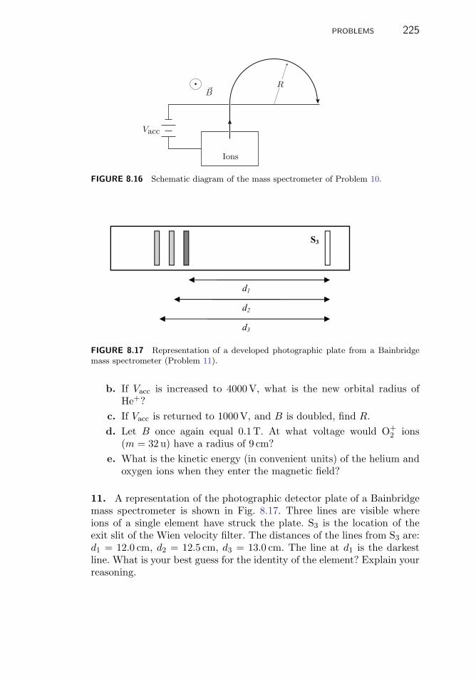
PROBLEMS 225
Ions
B�
Vacc
R
FIGURE 8.16 Schematic diagram of the mass spectrometer of Problem 10.
S3
d3
d2
d1
FIGURE 8.17 Representation of a developed photographic plate from a Bainbridgemass spectrometer (Problem 11).
b. If Vacc is increased to 4000V, what is the new orbital radius ofHe+?
c. If Vacc is returned to 1000V, and B is doubled, find R.d. Let B once again equal 0.1T. At what voltage would O+
2 ions(m = 32 u) have a radius of 9 cm?
e. What is the kinetic energy (in convenient units) of the helium andoxygen ions when they enter the magnetic field?
11. A representation of the photographic detector plate of a Bainbridgemass spectrometer is shown in Fig. 8.17. Three lines are visible whereions of a single element have struck the plate. S3 is the location of theexit slit of the Wien velocity filter. The distances of the lines from S3 are:d1 = 12.0 cm, d2 = 12.5 cm, d3 = 13.0 cm. The line at d1 is the darkestline. What is your best guess for the identity of the element? Explain yourreasoning.

226 8. MAGNETIC FIELD AND MAGNETIC FORCE
2 mm
5 mm
400 V
20 keV
(a) (b)
BE
FIGURE 8.18 A beam of electrons passes (a) through an electric field (Problem 12)and then (b) through a magnetic field (Problem 13).
12. An electric field is produced by applying a potential difference of400V between two parallel plates spaced 2mm apart (see Fig. 8.18).A beam of 20 keV electrons is sent between the plates along the x-axis.
a. What is the momentum px of the electrons as they enter the spacebetween the plates?
b. If the plates are 0.5 cm long, what is the change in momentum Δpy
from the time the electrons enter the space between the plates tothe time they emerge?
c. With no voltage across the plates, the electrons travel on from theplates and strike some point on a screen 15 cm away. Turning on thevoltage across the plates causes the electrons to strike a differentpoint on the screen. What is the distance between the points thatthe electrons strike with voltage off and with voltage on?
13. Now the electric field in the previous problem is turned off and auniform magnetic field is made to fill the space between the plates. Thedirection of B, the magnetic field, is out of the plane of Fig. 8.18.
a. In what direction will the electrons be deflected?b. For what value of B will the magnitude of the change in momentum
Δpy of the electrons passing between the plates be the same as thatproduced by the electric field of the previous problem?
14. In a Wien velocity filter (page 210), perpendicular electric and mag-netic fields are applied to moving charges so that only those charges withvelocity v = E/B pass through the fields without deflection. Figure 8.19illustrates a complementary situation: charged particles moving througha conducting material (such as electrons moving through a copper wire)are confined by the walls of the conductor so that they move in straightlines parallel to the axis of the conductor. A magnetic field applied per-pendicular to the motion causes the moving negative charges to separate
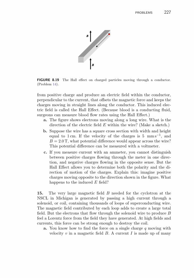
PROBLEMS 227
B
B
B
B
FIGURE 8.19 The Hall effect on charged particles moving through a conductor.(Problem 14).
from positive charge and produce an electric field within the conductor,perpendicular to the current, that offsets the magnetic force and keeps thecharges moving in straight lines along the conductor. This induced elec-tric field is called the Hall Effect. (Because blood is a conducting fluid,surgeons can measure blood flow rates using the Hall Effect.)
a. The figure shows electrons moving along a long wire. What is thedirection of the electric field E within the wire? (Make a sketch.)
b. Suppose the wire has a square cross section with width and heightequal to 1 cm. If the velocity of the charges is 5 mms−1, andB = 2.0 T, what potential difference would appear across the wire?This potential difference can be measured with a voltmeter.
c. If you measure current with an ammeter, you cannot distinguishbetween positive charges flowing through the meter in one direc-tion, and negative charges flowing in the opposite sense. But theHall Effect allows you to determine both the polarity and the di-rection of motion of the charges. Explain this: imagine positivecharges moving opposite to the direction shown in the figure. Whathappens to the induced E field?
15. The very large magnetic field B needed for the cyclotron at theNSCL in Michigan is generated by passing a high current through asolenoid, or coil, containing thousands of loops of superconducting wire.The magnetic field contributed by each loop adds to create a large totalfield. But the electrons that flow through the solenoid wire to produce Bfeel a Lorentz force from the field they have generated. At high fields andcurrents, this force can be strong enough to destroy the coil.
a. You know how to find the force on a single charge q moving withvelocity v in a magnetic field B. A current I is made up of many

228 8. MAGNETIC FIELD AND MAGNETIC FORCE
1 m1 m
FIGURE 8.20 Geometry of the current loop for Problem 15.
such moving charges. Go back to Sect. 6.3 (p. 160) to find anexpression for I in terms of the number of charges per unit volume,and then derive an expression for the force on a long straight wireof length L carrying a current I in a direction perpendicular to auniform magnetic field B.
b. Consider a single loop of the solenoid, which for simplicity take tobe square-shaped with side length 1m, carrying a current of 100 Ain the sense shown in Fig. 8.20. What is the direction of the fieldwithin the loop? What is the direction of the force on each of thefour sides of the loop?
c. If B = 5 T, as in the NSCL K500 magnet, find the magnitude ofthe force on each side of the loop. Assume that the field is uniform.Compare this force to your weight. In magnets made with coils ofsuperconducting wire great care must be used to assure that thereare no small movements of coil wires because these can generateenough heat to turn off the superconductivity with the result thatthe energy stored in the magnetic field explosively dissipates in thecoils. Designing a stable solenoid is not an easy task!

99C H A P T E R
Electrical Atomsand the Electron
9.1 INTRODUCTION
One important result of physicists’ increased understanding of electricityand magnetism was the recognition that atoms are electrical in nature. Inthe 1830s Michael Faraday’s1 studies of the flow of electricity through so-lutions contributed evidence that electricity is itself “atomic,” i.e., madeup of small indivisible units of electric charge. In 1894, G.J. Stoney pro-posed the word “electron” as the name for such a natural unit of charge.In 1897 the British physicist J.J. Thomson used electric and magneticdeflection to establish the existence of the tiny particle of electricity thatwe now call “the electron.” His work also showed that the electron is afundamental component of every atom and intimately related to its chem-ical properties. By the end of the first decade of the twentieth century theAmerican physicist Robert A. Millikan had measured the electron’s massand charge to within one percent.
The experiments that led to the discovery of the electron and revealedits properties are good examples of how physicists use physics to discovermore physics. These experiments illustrate the kinds of physical evidencethat physicists find persuasive. They are also direct applications of the
1Michael Faraday, 1791–1867, born of a poor family near London, received only the equivalentof an elementary school education. Apprenticed to a bookbinder at thirteen, Faraday took toreading everything he could find, especially scientific books. Attendance at some lectures onchemistry by Sir Humphrey Davy led to his applying for and receiving a position as assistant toDavy. From this beginning, Faraday trained himself in science to the point where his discoveriesin chemistry and electromagnetism, as well as his extremely popular public lectures, broughthim renown and many honors.
C.H. Holbrow et al., Modern Introductory Physics, Second Edition, 229DOI 10.1007/978-0-387-79080-0 9, c© Springer Science+Business Media, LLC 1999, 2010

230 9. ELECTRICAL ATOMS AND THE ELECTRON
laws of electricity and magnetism laid out in the previous two chapters,and their results have led to pervasive, contemporary technologies thatprofoundly shape our lives today.
9.2 ELECTROLYSIS AND THE MOLE OF CHARGES
As early as 1800, the passage of electric current through a solution wasknown to decompose it into elemental components. For example, Davy de-composed water into hydrogen and oxygen gas in this way. In the 1830s,Michael Faraday studied the passage of electric current through fluidsthat are good conductors of electricity. A brine solution, sodium chlo-ride dissolved in water, is a good example.2 Acid and base solutions alsoare good conductors. From this work Faraday deduced that electricallycharged atoms, “ions” as he named them, are the conductors of elec-tricity in solutions. He established quantitative relationships between theamount of charge that passed through a solution and the amount of eachelement that was produced.3
Faraday called solutions that could be thus electrically decomposed“electrolytes.” He invented several new words to describe the processeshe observed. Some of these and their definitions are
electrolyte: A solution through which electricity can flow.
electrode: The (usually) metal pieces inserted into the electrolyte topass the electrical current into and out of the solution.
electrolysis: The electrically induced breakup of molecules in theelectrolyte when current flows through it.
anode and cathode: Respectively, the positively and negatively chargedelectrodes.
ions: The bodies, charged atoms or molecules, that constitute an electriccurrent as they move through the electrolyte between the anode andthe cathode.
anions and cations: Ions that move to the anode are called anions; theyare negatively charged. Ions that move to the cathode are called cationsand are positively charged.
2Ordinary tap water has enough dissolved material to be a pretty good electrical conductor,which is why you should not stand in a puddle of water during a lightning storm or becomean electrolytic cell by touching a live wire.3See Great Experiments in Physics. Morris H. Shamos, Ed., Holt and Co., New York, 1959,p. 128, for extensively annotated excerpts from the original publications of Faraday on elec-trolysis and electromagnetism, as well as from the works of other important physicists. Shortbiographies of the pioneers we are discussing in this chapter are also included.

9.2. ELECTROLYSIS AND THE MOLE OF CHARGES 231
Faraday varied the nature of the electrolyte and the size and shapeof the electrodes. He tried different arrangements of electrodes to ensurethat when gases were the product of decomposition all the evolved gaswas collected. When sufficient care was taken, the universal result, nowknown as Faraday’s law of electrolysis, was that the measured amount ofa substance decomposed was “in direct proportion to the absolute quantityof electricity [i.e., total charge] which passes.”
� EXAMPLES
1. In one experiment with zinc and platinum electrodes immersedin water,4 Faraday observed that hydrogen gas was generated from theplatinum electrode while zinc oxidized and left the zinc electrode. Fara-day collected the hydrogen gas and determined that it was released bythe electrolysis of an amount of water that has a mass of 2.35 grains.Before electrolysis, the zinc electrode weighed 163.10 grains; after elec-trolysis it weighed 154.65 grains. This means that during the electrolysisof 2.35 grains of water, 8.45 grains of zinc were removed from the zincelectrode.4
If for every molecule of H2O that is electrolyzed, one Zn atom isremoved from the zinc electrode, then the ratio of the masses of theelectrolyzed water and zinc should equal the ratio of their molecularweights. From Faraday’s data
MZn = MH2O
8.45 grains of Zn2.35 grains of H2O
= 18 × 3.60 = 64.7 u,
which agrees well with today’s accepted atomic mass of 65.4 u for Zn.Notice that in this example it is not necessary to know the SI
equivalent of a grain.
Although in his day there was no way to measure the amount of chargepassed through an electrolyte, Faraday could make a current I that heknew was steady (constant). Then the amount of charge Q passed throughan electrolyte is proportional to the elapsed time Δt because Q = I Δt.If he ran the same steady current I through different electrolytes for thesame length of time Δt, the total amount of charge Q passed througheach electrolyte would be the same. He weighed the amounts of different
4Pages 254–255 in Michael Faraday, Experimental Researches in Electricity (3 vols. bound as2), Dover Publications, Inc., New York, 1965. The three volumes were originally published in1839, 1844 and 1855 respectively.

232 9. ELECTRICAL ATOMS AND THE ELECTRON
TABLE 9.1 Relative masses of elements produced by electrolysis using the sameamount of charge
Element hydrogen oxygen chlorine iodine lead tin silver
Relative mass 1 8 36 125 104 58 108
Atomic weight 1 16 36 125 208 116 108
elements released by the passage of the same amounts of charge Q anddiscovered that the ratios of the weights were closely related to the ra-tios of the elements’ atomic masses. You can see from Table 9.1 that forhydrogen, chlorine, and iodine the ratio of the weights collected is ex-actly the same as the ratio of their atomic masses. In other words, theamount of charge that releases one atomic weight (i.e., 1 mole) of hy-drogen releases one atomic weight of chlorine, iodine, or silver, but thesame amount of electricity releases only half a mole of oxygen, lead, ortin. Once again, simple integer ratios are strong evidence for atomicity. InChap. 3, it was atoms of matter; here it is evidence for atoms of electriccharge.
When it became possible to measure charges accurately, the amount ofcharge required to electrolyze exactly one mole of hydrogen, or silver, orchlorine, was found to be 96 485 coulombs. In other words, 96 485C willcause the electrolytic deposition of one gram atomic weight of silver, i.e.,107.88 g, which is one mole of silver atoms.
Therefore, even without knowing the value of Avogadro’s number NA
it appears quite reasonable to identify this quantity of charge, 96 485C,as NA basic charges. This suggests that there exists some basic, ele-mentary charge and that 96 485C is a mole of them. This quantity ofelectricity, the mole of elementary charges, is called “the faraday” and isoften represented by the symbol F . If we designate this smallest possiblequantity of electric charge by the symbol e (for elementary), then thefaraday is
F = NAe = 96485C. the faraday (1)
Figure 9.1 shows a typical setup for electrolysis along with a simplifiedmodern interpretation of what goes on in the process.
� EXAMPLES
2. Suppose that a cell arranged as in Fig. 9.1 carries a current of 15amperes for 10 min. How much silver will plate out on the cathode?

9.2. ELECTROLYSIS AND THE MOLE OF CHARGES 233
Anode Cathode
Ag+
Ag+
Ag Ag
Ag+
NO3–
+H2O
+ –
I
FIGURE 9.1 An electrolytic cell in which silver dissolves from a silver anode andplates onto the cathode.
The amount of charge, Q, delivered by this current during thisamount of time is (15C/s)(10min)(60 s/min) = 9000C. As a fractionof a faraday F this is
Q
F=
900096/, 485
= 0.0933,
which from the definition of F must be the same fraction of silver’smole atomic weight of 107.88 g. Thus:
Deposited Wt. of Ag = (107.88 g/mol)(0.0933mol) = 10.06 g.
Faraday’s work strongly suggested that chemical reactions involve inte-ger amounts of some basic quantity of electric charge. In conjunction withthe chemical evidence for atoms, these results led to the idea of an integernumber of these basic charges accompanying ions in solution. Faradayeven was so bold as to suggest that it is the electrical charges that arethe source of chemical “affinity,” or bonding, as we would say now.
� EXERCISES
1. Faraday’s results are shown in Table 9.1 along with the knownatomic weights. Use these data to deduce the number of faradays re-quired to produce one mole of each of the elements he studied. Assumethe possibility of different numbers of elementary charges on different

234 9. ELECTRICAL ATOMS AND THE ELECTRON
ionic species (which Faraday apparently did not consider) and explainwhy a faraday of charge might not always generate a mole atomicweight. Explain each of the six results reported in the table.
Note that Eq. 1, the definition of the faraday F , intimately connects Fwith Avogadro’s number and the elementary charge e. If you can deter-mine any two of the three quantities NA, F , or e, Eq. 1 will give you thethird.
� EXERCISES
2. In Chap. 5 you saw that a rough estimate of Avogadro’s number(≈6.6×10²³) could be obtained from kinetic theory and measurementsof the viscosity of air. Using this result and the value of the faraday,estimate a value for the elementary charge e.
In electrolysis a given amount of charge releases a certain mass of anelement. You can use this result to find the ratio of an ion’s charge to itsmass. For example, a charge Q = Ne will release N atoms of hydrogen,and the total mass released will be NmH, where mH is the mass of ahydrogen atom. The charge-to-mass ratio is found from the ratio of thetotal charge used to the total mass collected:
Qtotal
Mtotal=
Ne
NmH=
e
mH.
� EXERCISES
3. You know that one faraday of charge releases one mole of hydrogenatoms. From that fact determine the value of the charge-to-mass ratioof the hydrogen ion.
4. Modify this calculation to find the charge-to-mass ratio of theoxygen ion with charge −2e.
5. Of all the possible singly charged ions that one can imagine formingfrom the periodic table of the elements, which one will have the largestvalue of its charge-to-mass ratio? The smallest?

9.3. CATHODE RAYS, e/m, AND THE ELECTRON 235
Keep this result in mind for comparison with the charge-to-mass ratioof the elementary charge discussed in the next section.
9.3 CATHODE RAYS, e/m, AND THE ELECTRON
By the 1850s it had become possible to generate large electrical potentialsthat could supply sustained electrical currents. When a strong currentwas passed through a low-pressure gas in a glass container (tube), thegas would glow. Also rays were observed to stream from the cathode (thenegative electrode) to the walls of the tube or to the anode. The study ofthese so-called “cathode rays” led to two revolutionary conclusions: atomshave parts; the parts are electrically charged. One of these electricallycharged parts of the atom was the electron, an entirely new entity with amass almost 2000 times less than the mass of hydrogen, the lightest atom.
The Electrical Nature of Cathode Rays
To prove the electrical nature of cathode rays was not easy. First, the ideaof electrical particles was novel; second, if the rays were electrical theyshould be deflected both by magnetic fields and by electric fields. Butelectric deflection did not appear to occur. Although a magnetic field bentthe rays as you would expect if they were electrical charges,5 electric fieldsdid not appear to affect them. In 1883 when the able German physicistHeinrich Hertz tried to deflect the rays by passing them through theelectric field between two charged plates, he saw no effect and concludedthat cathode rays were not electrical. Only later was it found that thelack of electrical deflection was caused by poor vacuum.6
In 1887 J.J. Thomson7 began experiments that proved that cath-ode rays are electrical in nature. He also produced clear evidence thatmagnetic and electric fields bend cathode rays as though they have awell-defined, distinct ratio of charge e to mass m. This finding strongly
5Even when magnetic deflection was observed, it was not easy to understand. These were thefirst observations of particles with well-defined charges moving in magnetic fields, and mostphysicists of that time did not yet have the convenient tool of vector representations or all the“hand rules” that make it so easy (?) for you to predict the motion of charges in a magneticfield.6Hertz’s experiment used a vacuum at the edge of what was technically possible in his time,and it was not good enough. Ionization of residual gas in his cathode-ray tube produced enoughconductivity to short circuit the applied voltage and reduce the electric field to a value too lowto produce any deflection.7Joseph J. Thomson, 1856–1940. See Shamos, op. cit., p. 216. For an interesting account ofThomson and his work see http://www.aip.org/history/electron/jjhome.htm.

236 9. ELECTRICAL ATOMS AND THE ELECTRON
suggested that cathode rays are streams of distinct particles. We call theseparticles “electrons.” For being the first to exhibit its existence and fordetermining some of its properties, Thomson is considered the discoverer(in l897) of the electron.8
Using several different configurations of electrodes and tubes and bend-ing the rays with a magnet, Thomson showed that the observed electricalcharge was associated only with the rays. With improved vacuum tech-nique Thomson showed that cathode rays are deflected by electric fieldsas they should be if they are electrically charged. He also showed that theheat generated in the anode when struck by cathode rays is equal to theelectrical energy given to the beam by the voltage between the cathodeand the anode.
Here is a simplified version of how to compare the heat energy collectedin the anode with the kinetic energy in the beam. Build a metal cup of ashape that will collect all the rays coming from the cathode. Before youput this cup into the tube, measure how much heat energy raises the cup’stemperature by 1K. Say your result is 0.02 J.
Put the cup in a tube and pump out the air. Apply a potential differenceof 400V between the cathode and anode and observe that the cathode-raybeam current I is 2.0μA at the anode. Collect this beam in the anodefor 100 s, and observe that the temperature of the anode rises by 4.0 K.Because the temperature rises 1K for every 0.02 J added, you calculate—assuming no serious losses by cooling—that the anode received 0.08 J ofenergy.
Now compare the energy heating the anode with the kinetic energycarried by your beam of cathode rays. In time Δt the beam delivers atotal charge of Q = IΔt that has been accelerated through a potentialdifference V and therefore has energy K = QV , making the total kineticenergy brought to the anode K = V IΔt. For V = 400V, I = 2μA, andΔt = 100 s, K = 400 × 2 × 10−6 × 100 = .08 J.
The energy of heating equals the kinetic energy imparted electricallyto the beam. This result supports the supposition that cathode rays areelectrically charged.
Deflection
By Thomson’s time pumps could produce vacuums good enough to permitelectric deflection. Consequently, he was able to combine electric deflection
8For his discovery Thomson was awarded the 1906 Nobel Prize in Physics—http://nobelprize.org/nobel prizes/physics/laureates/1906/index.html.

9.3. CATHODE RAYS, e/m, AND THE ELECTRON 237
Va
Va
Vd
Vd
l
y
L(a)
(b)
S
FIGURE 9.2 Thomson’s arrangement of electric and magnetic fields to deflect cathoderays. The screen S on which the deflection was observed is at the extreme right.
with magnetic deflection and measure the charge-to-mass ratio e/m ofcathode ray particles. This section explains how he did this and why hehad to use both kinds of deflection.
Electric deflection is commonly achieved by passing a beam of chargedparticles between oppositely charged parallel plates as shown schemati-cally in Fig. 9.2. You have seen that in the volume between such plates theelectric field E is constant. While the beam is passing between the plates,the electric field exerts a constant force on the beam, upward in the caseshown in Fig. 9.2. The deflection is usually measured by looking at theluminous spot made when the beam strikes a screen a distance L fromthe deflecting plates. When the field is off, the beam strikes one point onthe screen; when the field is on, the spot is deflected some measurabledistance y.
You can predict the amount of deflection by calculating the angle θ atwhich the beam emerges from between the plates when E is on. Assumethe beam enters the region between the plates with a horizontal speedvx but no upward motion. Because the field E exerts an upward force onthem, the cathode rays leave the region between the plates with an upwardspeed of vy. Because these particles still have their original horizontalspeed vx, they travel the distance L to the screen in a time t such thatvxt = L. In that same time t they travel vertically a distance y = vyt.

238 9. ELECTRICAL ATOMS AND THE ELECTRON
The result is that
y
L=
vyt
vxt=
vy
vx= tan θ. (2)
It is useful to think of deflection as produced by a change of momentum.Multiply the top and bottom of Eq. 2 by the mass m, and you see thatthe deflection angle is also the ratio of a beam particle’s acquired upwardmomentum Δpy to its horizontal momentum px.
tan θ =mvy
mvx=
Δpy
px.
The cathode rays are deflected because a force acts for some timeinterval Δt in the y direction on each particle. Each is traveling withmomentum px in the x direction.9 The force, acting over time, impartsan increment of momentum Δpy in the y direction. When the force isapplied for only a short time, you can think of it as a blow or swat inthe y direction, as when a soccer ball rolls in the x direction across yourpath, and you kick it in the y direction. It doesn’t go directly off in the ydirection; rather, it is deflected and travels away from the x direction atsome angle θ = tan−1
(Δpy
px
)where Δpy is the effect of your kick.
� EXERCISES
6. Why is the horizontal momentum px not affected by the electricfield between the plates?
In Thomson’s experiment the cathode rays pass quickly between theplates and experience a kick from the electric field E. Each charge eexperiences a constant force Fy = Ee during the time Δt it is in theregion between the plates, and gets a kick of Δpy = Fy Δt. If the lengthof these plates is � and the speed of the electrons is vx, then
Δt =�
vx.
Because px is mvx, the angle of deflection is
θ =Δpy
px=
EeΔt
px=
eE�
mv2x
,
9This is a good description of what happens to the cathode rays, but in general the deflectingforce need not be constant or at right angles to the initial path of the deflected particles.

9.3. CATHODE RAYS, e/m, AND THE ELECTRON 239
where tan θ has been replaced by θ because, as is often the case, Δpy <<px, and the small-angle approximation is valid. To find y, just multiply θby the distance to the screen:
y = Lθ =eE�L
mv2x
. (3)
As expected, y depends on e, m, and vx.Electric deflection is a basic tool for controlling charged particles of all
kinds. As Eq. 3 shows, electric deflection is inversely proportional to thekinetic energy of the particle being deflected; this is a general property ofelectric deflection.
The above calculation of displacement on the screen neglects y-displacement occurring while the cathode ray particles are between theplates. In cathode ray tubes, this is usually negligible compared to theamount of displacement that occurs after leaving the plates, but it is nothard to include it if you need to. (For example, see p. 261.)
Equation 3 was not enough for Thomson to find the value of e/m ofcathode rays. He could measure y and E, but not vx. You might think hecould use the fact that he gave the rays their kinetic energy by acceleratingthem through a known voltage Va (subscript “a” for acceleration). As aresult
12mv2
x = eVa,
but, as you can show, using this equation to eliminate vx from Eq. 3 alsoremoves e and m from the equation.
� EXERCISES
7. Show that this last statement is true.
In contrast to electric deflection, magnetic deflection of a particle isinversely proportional to its velocity or, equivalently, its momentum. Thisproperty allowed Thomson to use magnetic deflection to determine vx inEq. 3 without eliminating e/m from the equation. First, he measured thedeflection y caused by the electric field E; then he produced in the regionbetween the plates a uniform B field with just the right strength to cancelthe deflection due to E. The effects of the two fields cancel when
eE = evxB,
or
vx =E
B. (4)

240 9. ELECTRICAL ATOMS AND THE ELECTRON
(This is the condition for the Wien velocity filter discussed on p. 210.)Thomson could determine both B and E, which meant that he couldreplace vx in Eq. 3 with its experimentally determined value. Or he couldsubstitute Eq. 4 into Eq. 3 and solve to get
e
m=
Ey
B2�L, (5)
where everything on the right side was measurable. These early mea-surements were not very precise; one value Thomson obtained was0.71 × 1011 C/kg, about a factor of 2.5 less than the currently acceptedvalue.
� EXERCISES
8. Derive Eq. 5.
9. If the separation between the plates was d = 5mm and the deflect-ing voltage Vd (d for deflection) was 104 V, what was the value of thedeflecting electric field?
10. You’ve seen that Thomson’s experiments determined only thecharge-to-mass ratio of cathode rays. How then did the mass spec-trometry experiment described in Chap. 8 use a combination of electricand magnetic fields to determine ratios of the masses of charged ions?What additional assumption allows you to infer the mass ratios frommass spectrometry?
e/m by the Bainbridge Method
All methods of measuring e/m use both electric and magnetic fields. In theBainbridge method shown in Fig. 9.3, a large tube is situated between twocoils that produce a reasonably uniform magnetic field B. This field bendsthe cathode rays in a circle with a radius r that depends upon the particlemomentum and the strength of the magnetic field. The beam of cathoderays is produced by a small “electron gun” oriented to inject electronstangent to the circumference of the tube so that the beam can make aslarge a circle as possible. The gun gives the electrons kinetic energy byaccelerating them across a potential difference of Va volts. With a chargee and mass m, each electron gains a kinetic energy of
12mv2 = eVa. (6)

9.3. CATHODE RAYS, e/m, AND THE ELECTRON 241
Gr
VacuumtubeMagnetic field B
(out of page)
Va
FIGURE 9.3 Diagram of an apparatus for measuring e/m. The source of electrons Gdirects a beam accelerated through a voltage Va in a downward direction. An externalmagnetic field B bends the beam in the circle with a radius r as shown.
In modern versions of the Bainbridge apparatus the tube is evacuatedduring its manufacture and then refilled to a low pressure with an inertgas such as helium. When electrons pass through this gas, they cause itto glow, and the path of the rays becomes visible so that an observer canmeasure the radius of curvature r of the electron beam.
The external magnetic field B produces a force on the moving chargesperpendicular to their path. This force supplies the centripetal force Fc
that produces circular motion. Thus
Fc =mv2
r= evB, (7)
where r is the radius of the circle. Solve for v,
v =eBr
m,
then square the result and substitute into Eq. 6 to get
2eVa
m= v2 =
e2B2r2
m2
ande
m=
2Va
B2r2. (8)
Every quantity on the right side of Eq. 8 is measurable, so e/m can bedetermined. The modern value is
e/m = 1.759 × 10¹¹ C/kg.

242 9. ELECTRICAL ATOMS AND THE ELECTRON
� EXAMPLES
3. In Fig. 9.3, suppose that a radius of 8.0 cm is measured and theaccelerating voltage is 400V. What magnetic field is being used tobend the cathode rays?
Solving Eq. 8 gives
B2 =2V
(e/m)r2
from which it follows that
B =
√2 × 400
1.76 × 1011 × (8 × 10−2)2T (for tesla).
Evaluating this expression gives
B =√
7.10 × 10−7 = 8.43 × 10⁻⁴ T.
To check that the units are correct it may help if you use Eq. 4 to see
that 1T = 1 N/Cm/s .
The Significance of e/m
Thomson’s value for e/m was remarkably large, or, to put it anotherway, the value of m/e was remarkably small. From experiments in elec-trolysis one finds that m/e for the hydrogen ion is about 10−8 kg/C(see Exercise 3). Thomson’s value of m/e for electrons was more thana thousand times smaller, indicating that in terms of mass the electronwas a very small part of the atom.
At least as important as its discovery was the recognition that theelectron was a part of every atom. The electrons measured in this appa-ratus must come from the electrodes or the gas in the tube, but the samecharge-to-mass ratio was measured when these materials were changed.This suggested that the electrons in every kind of atom are identical; thatis, electrons are a fundamental building block of atoms.
Furthermore, a year earlier H.A. Lorentz had shown that he could ex-plain a peculiar change that occurred in the frequency of light emittedby neutral atoms placed in a magnetic field if there was inside the atoma charged particle with a charge-to-mass ratio of about 2 × 10¹¹ C/kg,the same value to within experimental uncertainty as the value of e/mmeasured by Thomson for a free electron. This was strong evidence thatthe electron is an internal part of every atom and intimately involved inatomic behavior.

9.4. THE ELECTRON’S CHARGE 243
9.4 THE ELECTRON’S CHARGE
Introduction and Overview
It is important to know the value of the electron’s charge. It sets thescale of electric forces in atoms, and these forces determine atomic size.Moreover, knowledge of e yields NA from the faraday, and the mass ofthe electron from e/m. Consequently, after Thomson’s work, physicistssought to measure the value of the charge e directly.
The most conclusive of the direct measurements of e were made bythe American physicist R.A. Millikan.10 He obtained accurate resultsby studying the speed of motion in air of small electrically charged oildroplets moving under the influence of gravitational and electric fields.His work established that there is such a thing as an elementary indivisibleunit of charge and that its value is e = 1.6 × 10⁻¹⁹ C.
Millikan’s oil droplets were a few micrometers in diameter (a humanhair is about 100μm in diameter). When such a small droplet falls inair, it accelerates only briefly—until resistance from the viscosity of airbalances the force of gravity—after which it falls at a slow, steady speed.These droplets are too small to be seen directly, but when illuminated witha bright light against a dark background, an individual droplet scattersenough light to make a visible glint. Millikan could then measure its speedof fall very accurately. The apparatus to apply the necessary fields andilluminate the oil drops is illustrated in Fig. 9.4.
He made the droplets by spraying oil through a tiny nozzle, and frictionbetween the oil and the nozzle gave each droplet a tiny unknown charge.By measuring the speed vg of a droplet falling under gravity, Millikancould determine its mass. By measuring the speed vF of a droplet risingin an electric field, he could figure out how much electric charge the dropletcarried. He made hundreds of measurements using different charges bothon the same and on different droplets and found that all the charges onhis droplets were integer multiples of a single, smallest amount e—theelementary charge.
Droplet Size from Terminal Velocity
To understand the effects of electric field on his charged oil droplets,Millikan had to know their masses. He determined the mass of a droplet byan ingenious application of the fact that when a small, spherical body falls
10Robert A. Millikan, 1865–1953. See Shamos, op. cit., p. 238. The results of Millikan’sexperiment are reported in Physical Review 32, 349 (1911).

244 9. ELECTRICAL ATOMS AND THE ELECTRON
vg
qE
vF
Fv
Fv
mg mg
V
field FieldNo
(a)
(b)
Telescope
FIGURE 9.4 (a) Millikan’s apparatus for determining the charge of an electron. (b) Acharged droplet of oil can be observed through a telescope to fall at terminal velocityvg between parallel plates in the absence of any electric field and to rise with terminalvelocity vF when an electric field E is present.
freely through a viscous medium, it quickly stops accelerating and fallsat a steady rate vg called its “terminal velocity.” The terminal velocityvg depends on the acceleration due to gravity, g, on the viscosity η ofthe medium, on the sphere’s radius a, and on the density ρ of the oil ofwhich the droplet was made. Millikan measured the terminal velocity of afalling droplet and from his knowledge of g, η, and ρ, found its radius a.Then he calculated the mass m of the spherical droplet from the fact thatm = 4
3πa3ρ.
� EXAMPLES
4. If a spherical droplet of oil of density ρ = 0.92 × 10³ kg m−3 hasa radius of 1μm, what is its mass m? Because the mass of the sphereequals its volume times the density of the oil, you get
m =43π(1 × 10⁻⁶)3 (0.92 × 10³) = 3.9 × 10⁻¹⁵ kg = 3.9 pg.
How do you find the droplet’s radius a from its speed of fall vg? Think ofan oil droplet falling freely through the air inside the chamber of Millikan’s

9.4. THE ELECTRON’S CHARGE 245
experimental apparatus (Fig. 9.4) with the electric field turned off. Twoforces act on the droplet: gravitational attraction downward and viscousdrag opposing the droplet’s motion. The gravitational force is just mg.The retarding viscous force due to the air is proportional to the viscosity ofair and to the droplet’s velocity. The British physicist Sir George Stokesshowed in the nineteenth century that the viscous force Fv acting ona small sphere of radius a falling with velocity v through a fluid withviscosity η is
Fv = 6πηav. (9)
Consider what happens when the droplet falls. It starts off with anacceleration of g, but as its velocity increases, the retarding viscousforce increases, opposing the gravitational attraction and decreasing thedroplet’s acceleration. As the value of v continues to increase, the accel-eration continues to decrease until the droplet reaches the velocity vg atwhich the force Fv retarding the droplet just equals mg, the force of grav-ity downward. At this velocity vg the opposing forces are balanced, theacceleration goes to zero, and the velocity stops changing. The velocityvg at which this balance occurs is called the “terminal velocity.”
You can find an expression for vg in terms of the droplet radius aand density ρ. Begin by equating the viscous and gravitational forces,Fv = mg, and solving for vg:
6πηavg = mg,
vg =mg
6πηa. (10)
Now express m in terms of a and the known density of the oil, (ρ =0.92 g/cm3 for the oil Millikan used), m = 4
3πa3ρ; substitute for m inEq. 10 and do some algebra to get
vg =29
ρga2
η. (11)
Millikan measured vg and used the known values of ρ, g, and η to find theradii and masses of droplets.
� EXERCISES
11. Derive Eq. 11 from Eq. 10.

246 9. ELECTRICAL ATOMS AND THE ELECTRON
� EXAMPLES
5. How slowly does a droplet fall through air if its radius is only 1μm,i.e., what is its terminal velocity? Assume that the density of the oil isρ = 0.92 g cm−3 and the air temperature is 20 ◦C.
From Chap. 5 you know that for air η = 18.3 μPa s. Now use Eq. 11:
vg =29
(0.92 × 10³)(9.8)(1 × 10⁻⁶)2
18.3 × 10−6= 1.1 × 10⁻⁴ m/s.
A droplet 1μm in radius will fall with a terminal velocity of 0.11mm/s;it will take 9 s to fall 1mm! For a small droplet in air this equilib-rium speed is reached almost immediately, and an observer will see thedroplet fall slowly at constant velocity.
� EXERCISES
12. What would be the terminal velocity of an oil droplet if it were10μm in radius?
To measure vg Millikan watched a falling droplet through a telescopeand measured the time tg it took the droplet to fall a known, small height hmarked by two reference lines in his telescope eyepiece. Then he calculatedthe terminal velocity as vg = h/tg. Knowing vg, he used the inversion ofEq. 11 to find the droplet radius
a =√
9vgη
2ρg,
and then found the weight of the droplet:
mg =4π3
a3ρ g =4πρ
3g
(9vgη
2ρg
)3/2
= 9π(
2η3
ρg
)1/2
v3/2g . (12)
Using his oil drop technique, Millikan could weigh a tiny oil droplet.Knowing the weight of the droplet, he could then determine how muchelectric charge q was on it.
� EXERCISES
13. Suppose a droplet has a terminal velocity of 0.43mm/s. What isits radius and mass? Efficiency tip: Use the values worked out for a 1μmradius drop and scaling arguments to avoid unnecessary calculation.

9.4. THE ELECTRON’S CHARGE 247
14. How big is the viscous force acting on the 1μm-radius dropletwhen it is moving with terminal velocity? On the 10μm droplet?
Finding the Charge on a Droplet
By applying an electric field Millikan could cause the charged dropletsto rise. Turning the field repeatedly on and off, he could cause an indi-vidual droplet to rise and fall repeatedly as he observed its motion forhours. From the speeds of fall and rise that he measured, Millikan coulddetermine the amount of charge on a droplet. He could also change theamount of charge on a given droplet, measure changes in its speed of rise,and calculate by how much the droplet’s charge had changed. Here’s howhe did these things.
Millikan produced an electric field E by applying a potential differenceV to a pair of metal plates separated by a small distance d. As notedearlier, this creates a constant electric field E = V/d between the plates.When the field is on, the droplet experiences a force qE in addition to thedownward force mg. The force qE could be either upward or downward,depending on the sign of q and the direction of E. However, Millikan wasonly able to experiment with particles that rose under the influence of theelectric field; other particles would quickly fall out of the region he couldobserve in his telescope, so we’ll work out the theory for this case. Call theterminal velocity vF when the droplet is rising with the field turned on(F for field). When the electric field is off, the drop falls with a terminalvelocity vg (g for “gravity only”).
For a given drop there is a simple proportion between its terminalvelocity and the effects of gravity or the electric field acting on the droplet.As Eq. 10 shows
vg ∝ mg,
i.e., the downward terminal velocity is proportional to the downwardforce of gravity. When an applied electric field makes the droplet rise,the upward terminal velocity is proportional to qE − mg
vF ∝ qE − mg.
Divide the second expression by the first to get:vF
vg=
qE − mg
mg.

248 9. ELECTRICAL ATOMS AND THE ELECTRON
Solve for q:
q =mg
E
(vF
vg+ 1)
=mg
vgE(vF + vg). (13)
Now use the expression for mg from Eq. 12 in Eq. 13 to find the chargeon the droplet solely in terms of quantities that can be determined frommeasurements. You get
q =9πV/d
(2η3
ρg
)1/2
v1/2g (vF + vg). (14)
� EXERCISES
15. Derive Eq. 14.
16. Show explicitly that the right-hand side of Eq. 14 has units ofcoulombs when all the quantities are measured in SI units.
� EXAMPLES
6. For one particular droplet Millikan used a potential difference of5085V between two plates 16mm apart. When the electric field wasoff, the droplet fell with a speed of 0.08584 cm/s; when the field was on,the droplet rose with a speed of 0.01274 cm/s. What was the charge onthis droplet?
For ρ = 0.92 × 10³ kgm−3, η = 18.2μPa s, and g = 9.8m s−2, youfind from Eq. 14 that
q =9π 0.016
5085
√2(18.2 × 10⁻⁶)3(8.584 × 10⁻⁴)
920 × 9.8(15)
× (1.274 × 10−4 + 8.584 × 10⁻⁴)= 2.97 × 10⁻¹⁸ C.
Notice that this is not really what we want to know. It is the charge onthe given droplet; it is not the elementary charge. Only if a droplet hadexactly one unneutralized elementary charge would the above equationgive the value of the elementary charge. In fact a singly charged dropletcould not be made to rise in the electric field of Millikan’s apparatus, sohe never observed such a droplet. To get around this problem Millikanchanged the charge on a given droplet from time to time. He did this

9.4. THE ELECTRON’S CHARGE 249
by slightly ionizing the air of the chamber with x-rays or radioactivity.A droplet would then pick up one or more ionized molecules and changeits charge. As a result, the electric force on the droplet would change andso would the droplet’s terminal velocity vF . The velocity vg stayed thesame because the mass added to the oil drop by a few ions was utterlynegligible compared to the mass of the droplet. By measuring the changesin vF , Millikan could calculate by how much the charge had changed. Heobserved that this change was always an integer multiple of some smallestamount, 1.602×10⁻¹⁹ C by modern measurements. He concluded that thissmallest change corresponded to the elementary charge we denote as e.
� EXERCISES
17. How many elementary charges were there on the droplet referredto in Example 6?
18. Suppose the charge on a 1-μm radius droplet increased by 3ebecause it picked up three nitrogen ions. What would be the fractionalincrease in the droplet’s mass?
Quantization of Electric Charge
It is interesting that Millikan did not need actually to measure the valueof the elementary charge e in order to demonstrate experimentally thatthe electric charge on a droplet is always an integer multiple of e. His workis such a nice example of reasoning with ratios that it is worth lookingat closely. Table 9.2 is a reproduction of data that Millikan published11
to show the atomic nature of charge. (Other examples of Millikan’s datacan be found in Shamos’s book.) Along with the data, Table 9.2 showsvarious parameters of his apparatus, such as voltage V , spacing betweenthe plates d, the distance h of fall and rise of a droplet, etc. The datarecorded by Millikan are the values of the quantities actually measured.These are the times of fall under gravity, tg, and the times of rise whenthe field was on, tF . You can see that when he caused the charge on adroplet to change, the time of rise with the field on changed because theelectrical force qE changed.
There is enough information in the table so that from these times you(and he), using Eq. 14, could calculate the charge on every droplet. But
11R.A. Millikan, Electrons (+ and −), Protons, Photons, Neutrons, Mesotrons and CosmicRays, revised edition, University of Chicago Press, Chicago, 1947, p. 75.

250 9. ELECTRICAL ATOMS AND THE ELECTRON
TABLE 9.2 Data from Millikan’s measurements on an oil dropa,b
aTaken with permission from p. 75 of R.A. Millikan, Electrons (+ and −), Pro-
tons, Photons, Neutrons, Mesotrons and Cosmic Rays, University of Chicago
Press, c©1937 and 1947 by the University of ChicagobThe viscosity of air is given here in cgs units; the corresponding SI value is
18.24 × 10⁻⁶ Pa s
this would be neither efficient nor very insightful. Also, as noted in theprevious section, Millikan concentrated on the changes in charge. He didthis because these changes were smaller multiples of e than was the totalcharge on a droplet.
From Eq. 14 you can see that the change in charge Δq is
Δq =9πV/d
√2vgη3
ρg
(v′F − vF
), (16)
where v′F denotes the velocity of rise after the charge has changed andvF denotes the initial velocity of rise (before the droplet charge changed).

9.4. THE ELECTRON’S CHARGE 251
Notice that for a given droplet, Eq. 16 means that
Δq ∝ (v′F − vF
),
or, since v′F = h/t′F and vF = h/tF ,
Δq ∝(
1t′F
− 1tF
)
,
because the distance h over which the fall and rise times were measuredwas the same for every droplet.
If the values of the various occurrences of Δq are multiples of somesmall, elementary value, then so must also be the values of the var-ious occurrences of
(1t′F
− 1tF
). In columns 4 and 5 of Table 9.2 you
see Millikan’s examination of this possibility. All the different values of(1t′F
− 1tF
)are convincingly close to being small integer multiples of the
value 0.005386 s−1 .
� EXERCISES
19. How close to being exact integer multiples of 0.005386 s−1 are thefirst three entries in column 4 of Table 9.2?
20. Explain why Millikan probably would have found the same resultin column 6 of Table 9.2 even if there had not been an instance in whichthe charge changed by a single elementary unit.
Of course, if there is a basic “atom” of charge, then the total charge qon any droplet must be some integer multiple of it, and this quantity mustbe the same as the one of which any change in charge Δq is a multiple.From Eq. 14 it follows that
q ∝ (vg + vF ) ∝(
1tg
+1tF
)
.
Consequently, the quantity of which(
1tg
+ 1tF
)is an integer multiple
should be the same as the quantity of which(
1t′F
− 1tF
)is an inte-
ger multiple. Columns 7, 8, and 9 of Table 9.2 show this to be thecase—0.005386 s−1.

252 9. ELECTRICAL ATOMS AND THE ELECTRON
� EXERCISES
21. Explain why column 7 of Table 9.2 represents the total charge ona droplet (as distinct from the change in charge).
22. As well as showing the times of fall and rise, Table 9.2 lists theparameters of Millikan’s experiment.(a) Use these to show that the radius a is correctly calculated from hisvalues of viscosity, speed of fall, and oil drop density.(b) From these parameters and Millikan’s conclusion that the elemen-tary charge corresponds to
(1t′F
− 1tF
)= 0.005386 s−1 determine the
value of the elementary charge in coulombs.
Millikan reported data on over 50 droplets altogether. He excludedmeasurements on any trial when he thought the charge on the dropletchanged while he was measuring its speed in the electric field. In every caseboth the charge on a droplet and any change of that charge were integermultiples of a single value. The repeatability of these measurements isstrong evidence that a unique atomic unit of charge exists. That chargee is called the “elementary charge.” Often, somewhat carelessly ignoringits sign, people call e the “electron charge.” The quantity e is also themagnitude of the charge on singly ionized atoms such as hydrogen ionsand the like. The modern value for e is 1.602 × 10⁻¹⁹ C. The results youcan obtain from Table 9.2 are slightly different from this value of e becausethey have not yet been corrected for inaccuracies that occur in Stokes’slaw when the size of the droplet is comparable to the mean free path ofthe molecules through which it is falling. Millikan made these correctionsand obtained e = 1.593 × 10⁻¹⁹ C.12 Remember that the charge of anelectron is negative, although the quantity e is usually given as a positivenumber. It is your job to remember the sign when it is needed.
Important Numbers Found from e
From accurate knowledge of e came accurate knowledge of Avogadro’snumber, the mass of the electron, and an order-of-magnitude estimate of
12Millikan claimed that his value for e was accurate to about a tenth of a percent. However,when other techniques became available to measure atomic spacings in solids to high precision,the value for Avogadro’s number derived from these data disagreed with the value calculatedfrom Millikan’s e. The source of the discrepancy was ultimately traced to a slightly inaccu-rate value of the viscosity of air. Millikan used 18.240 μPa s; the currently accepted value is18.324 μPa s. Scale Millikan’s value for e by the ratio of these two numbers and see what youget for e.

9.5. SUMMARY 253
the energy of interaction of an electron with its atom. Knowing a pre-cise value of Avogadro’s number, you can calculate the actual mass inkilograms of any atom or molecule.
� EXERCISES
23. Calculate Avogadro’s number from e and the faraday F .
24. Show how once Millikan had measured the elementary charge, hecould determine that the mass of an electron is 9.11 × 10⁻³¹ kg.
Millikan’s result permits you to estimate with moderate precision theenergy of interaction of the electron with its atom. An electron a distanceof r0 = 0.1 nm—a reasonable number based on the sizes of atoms—froma singly charged ion will have a potential energy of −ke2/r0 = −14.4 eV.This number tells you roughly the amount of energy involved when atomsinteract with each other by means of their electrons. In other words, thisnumber tells you that the energy scale of chemistry is of the order of 10 eV.
9.5 SUMMARY
This chapter has examined three important contributions to our under-standing of atoms. Faraday’s studies of electrolysis and the regularitiesof electrolytic deposition showed that atoms have an electrical nature.The results hinted that electricity, like matter, has an atomic nature andthat there exists such a thing as a mole of charge and, therefore, somesort of atom of electrical charge, some basic unit of electricity. Thomsondiscovered the electron by using electric and magnetic fields to show thatin an electrical discharge in a gas the rays emanating from the cathode areparticles with definite mass and charge. Because the cathode-ray parti-cles were the same regardless of what kind of cathode material or residualgas was in the tube, his results supported other evidence that electronsare parts of all atoms. Millikan’s precise measurements of the electroniccharge confirmed the discrete nature of electricity and established the en-ergy scale of the electron’s interaction with an atom. His results yieldedprecise values of Avogadro’s number and of the electron’s mass as well asof its charge.
The indivisible “a-tom” had been cut, and two new, very important,questions arose at once. If the electron is in the atom, what does it dothere? And if the electron is one part of an atom, what are the other

254 9. ELECTRICAL ATOMS AND THE ELECTRON
parts? The answers to these questions led to a revolution in physics, butbefore you can understand this revolution, you need to study propertiesof light and other forms of electromagnetic radiation. This you do in thenext chapter. Before taking up this new topic, however, you might like tosee two interesting uses of electric fields to manipulate charged particles.
9.6 USES OF ELECTRIC DEFLECTION
A good idea can have many applications. You have seen how J.J. Thomsonused electric deflection to determine that cathode rays are charged par-ticles. Electric deflection of electrons has widespread application as thebasis of the cathode ray tube that is the heart of the oscilloscope, arguablythe most important instrument in all modern sciences. Electric deflectionis also used for low-cost, high-speed, good-quality printing and to huntfor quarks.
The Inkjet Printer
The inkjet printer works by electric deflection of objects orders of mag-nitude greater in size than electrons. In the inkjet printer ink dropletsare electrically charged and then steered by electric deflection so thatthe droplets form characters on paper. The essential features of an inkjetprinter are shown in Fig. 9.5. About 105 droplets are sprayed onto thepaper each second, with about 100 drops forming a single character.13
Each droplet has a diameter of 63 μm. Assuming that the dropletshave the density of water, this diameter corresponds to a droplet mass of1.31 × 10−10 kg. A controlled amount of electric charge between 80 and550 fC can be put on each droplet by varying the voltage on the chargeelectrode. The droplets pass in a stream at a speed of 18m/s between twosmall metal plates 1.3 cm long and 1.6mm apart. These are the deflectionplates.
How Much Can a Droplet Be Deflected?
If the maximum voltage that can be placed across the plates is 3.3 kV,what would be the maximum deflection of the ink drops on a piece of
13A quite detailed description of the considerations that went into the design of the inkjetprinter developed by IBM for the IBM 46/40 Document Printer is given in “Application of InkJet Technology to a Word Processing Output Printer,” W.L. Buehner, J.D. Hill, T.H. Williams,and J.W. Woods, IBM J. Res. Develop., 1–9 (Jan. 1977), and in other articles in this issue ofthe IBM Journal of Research and Development.

9.6. USES OF ELECTRIC DEFLECTION 255
128dro
ps
DeflectionplatesCharge
electrode
Dropgenerator
Pump
Ink
1.8 ms
Vce
Chargeelectrode
Controllogic
DAC
PumpDAC
High/low
High/low
signal
Sensor
sensors
circuits
paperpath
Planeof
Gutter
FIGURE 9.5 Inkjet printer showing droplet generator and charger along with de-flection plates. c©1977 International Business Machines Corporation. Reprinted withpermission of The IBM Journal of Research and Development, Volume 21, Number 1.
paper 1 cm away? You want to use a step-by-step approach to answer thisquestion; stepwise reasoning is usually the best way to solve problemsbecause it gives you more physical insight than blind use of an equation.
Notice that this printer is a scaled-up version of Thomson’s method fordeflecting electrons that was described in Sect. 9.3. A beam of chargedparticles with momentum px passes between a pair of charged plates andis deflected through some angle θ because the electric field between theplates imparts to the particles an increment of momentum Δpy perpen-dicular to their path. By varying E you can vary Δpy and control thedeflection angle according to the relation
tan θ =Δpy
px=
y
L,
where y is the vertical displacement a distance L from the deflectingplates.
� EXERCISES
25. How should the apparatus be designed so it can move the particlesto points other than on the y-axis?

256 9. ELECTRICAL ATOMS AND THE ELECTRON
How much is Δpy? It will be the product of the force qE and the timeinterval Δt during which that force acts. This time interval is just thelength of the plates � divided by the velocity of the particles v. Therefore,
Δpy =qE�
v=
qV �
vd
=550 × 10−15 × 3300 × 1.3 × 10−2
18 × 0.0016= 8.19 × 10⁻¹⁰ kgm s−1.
Then, to find θ you need to find px, the momentum along the x-axis.This is
px = mvx = 1.31 × 10−10 × 18= 2.36 × 10⁻⁹ kgm s−1,
from which you see that Δpy is about 13 of px; in fact,
tan θ =Δpy
px=
8.19 × 10⁻¹⁰
2.36 × 10−9= 0.347.
Over a distance L = 1cm from the deflection plates to the paper, thisangle of deflection will produce a displacement y on the paper such that
y
L= tan θ = 0.347,
from which it follows that
y = 1cm × 0.347 = 0.347 cm = 3.47mm.
With the distance to the screen L = 1cm and the length of the de-flecting plates � = 1.3 cm, the IBM inkjet printer differs markedly fromThomson’s arrangement in that L is not large compared to �. As a con-sequence, the amount of displacement that takes place while the chargedparticle is between the plates is no longer negligible compared to thedisplacement that occurs as the particle travels to the paper.
It is not very difficult to calculate the vertical displacement that occurswhile the particle is between the plates. Between the plates the displace-ment is just what occurs to a particle moving with a constant accelerationa = qE/m. That distance is the old, familiar (?) y = 1
2at2, where t = �/vx.The value of the acceleration is
a =qE
m=
qV
md
=5.5 × 10⁻¹³ 3300
1.31 × 10⁻¹⁰ 0.0016= 8.66 × 10³ m s−2;

9.6. USES OF ELECTRIC DEFLECTION 257
and the value of t is
t =�
vx=
1.3 × 10⁻²
18= 7.22 × 10⁻⁴ s.
From these two numbers you can calculate that
y =12at2 =
12(8.66 × 103) × (7.22 × 10−4)2
= 2.26 × 10⁻³ m,
which is 2.26mm and comparable in size to the 3.47mm of displacementthat occurs between the exit point and the paper. The total displace-ment of a droplet caused by electric deflection is therefore 2.26 + 3.47 =5.73mm.
Noticing that this calculation shows that the droplets will be deflected2.26mm between two plates that are 1.6mm apart, you may think thatthe droplets will hit the deflecting plates. This does not occur for tworeasons. First, air resistance reduces the amount of deflection from whatyou calculate by the arguments given here. Second, as Fig. 9.5 shows, oneof the plates is bent upwards to allow the maximally deflected dropletsto escape without hitting a plate.
Quark Hunting
Electric deflection of droplets produced and charged like those in an inkjetprinter has been used to look for quarks. Quarks are fundamental particlesof which most other particles (but not electrons) are thought to be made.The proton is made of three quarks. One very unusual feature of quarksis their electrical charge: It is a fraction(!) of the elementary charge e.One kind of quark is thought to have a charge of +2e/3 and another tohave −e/3. A burning question for over forty years has been, “Why hasno one ever been able to see an isolated quark with these very unusualcharges?”
It has not been for lack of searching. Quarks have been looked for inmine tailings, in seawater, in old stained-glass windows. They have beensought in niobium spheres and tungsten plates. They have been assid-uously pursued with high-energy accelerators and experiments of greatingenuity. But no one has ever found one. They seem to occur only ingroups inside other particles.

258 9. ELECTRICAL ATOMS AND THE ELECTRON
Separating Droplets by Deflection
One search for quarks used inkjet technology.14 The idea was to generatea series of droplets with different numbers of charges on them and letthem fall in a vacuum through a pair of electrically deflecting plates. Ifthe number of charges on a droplet is an integer multiple of e, then deflec-tions will occur in discrete amounts. For example, a droplet with a chargeof 21e will undergo a certain deflection and land a discrete distance awayfrom the landing points of droplets of charge 20e or 22e. The dropletsshould fall in narrow bands with spaces between them. If a fractionallycharged droplet came along, it would land in one of those spaces and sobe observable. Figure 9.6 shows the apparatus. Droplets of tetraethyleneglycol of mass m = 16 ng and diameter 2r = 30.1 μm were injected atthe top of a 22-m tall tower. The droplets were traveling at a speed ofv1 = 8.6m/s as they entered the 3.05-m long space between the deflectingplates where they were deflected by the electric field produced by a poten-tial difference of 20 kV between the plates, which were 5 cm apart. Afterexiting from between the deflection plates, the droplets fell about 15m toa detector that measured the amount of their sideways displacement.
Does this work? How much will be the separation between dropletswhen they are detected? Will there be enough space between the landingpoints of droplets that differ by one unit of charge so that you can distin-guish any fractionally charged particle if one happens to be present? Toanswer these questions you need to calculate the sideways displacementof a droplet carrying a charge of q = 20e for a deflecting voltage of 20 kV.
Because the tetraethylene glycol droplets are accelerating in the direc-tion of their motion under the force of gravity both as they pass betweenthe deflecting plates and afterwards, it is not adequate to find the angleat which the particles emerge from between the plates as was done in thecases of a beam of cathode rays or a stream of charged droplets of ink.Instead, you must find the sideways displacement x1 and the sidewaysvelocity vx at the time t1 the droplet emerges from between the platesand also calculate the time t2 that it takes the droplet to fall to the de-tector 15m below. The sideways displacement after exiting from betweenthe plates will be x2 = vxt2, and the total sideways displacement will bex1 + x2.
To find the sideways velocity vx as the droplets exit from between theplates, you need to use the sideways acceleration ax = qE/m producedby the electric field E during the time t1 that the droplet is in the field.Then vx = ax t1. But how do you find t1?
14“Search for fractional charges using droplet-jet techniques,” J. Van Polen, R.T. Hagstrom,and G. Hirsch, Phys. Rev. D36, 1983–1989 (1987).

9.6. USES OF ELECTRIC DEFLECTION 259
V–+
x1
x1
z1
x2
t=t1
t=0
t=t1+t2
15 m
Vac
PSD
LI
DR
Droplet(a) (b)
MPMP
FIGURE 9.6 (a) Schematic diagram of a 22-m high evacuated tube inside of whichcharged droplets fall and are electrically deflected: DR is the droplet source; LI is avibration isolator; V is the deflection voltage supply; MP is a mounting plate; Vac is theoutlet to the vacuum pump; and PSD is the position-sensitive detector that records thefallen drops. (b) Variables and quantities for analyzing the deflection of a droplet; theyare described in the text. Taken with permission from J. Van Polen, R.T. Hagstrom,and G. Hirsch, Phys. Rev. Vol. D36, 1983–1989 (1987), c©1987 American PhysicalSociety.
To find t1, use the fact that under constant acceleration the averagevelocity over some time interval t is (v2 + v1)/2, where v1 is the velocityat the start of the interval and v2 is the velocity at the end of the interval.Then the time t1 to fall a vertical distance z1 between the plates is
t1 =2z1
v2 + v1,
where v1 = 8.6m/s is the velocity of the droplet as it enters the electricfield between the plates and v2 is its velocity as it exits. Of course, thismeans you must find v2, but you can do this using the conservation ofenergy as was illustrated in Sects. 2.7 and 7.2.

260 9. ELECTRICAL ATOMS AND THE ELECTRON
� EXERCISES
26. Show that a body with an initial velocity v1 = 8.6m/s will havea velocity of v2 = 11.6m/s after it falls a distance z1 = 3.05m near thesurface of the Earth.
From these values of v1 and v2 you can deduce that
t1 =2z1
v2 + v1=
2 × 3.058.6 + 11.6
= 0.30 s.
To find ax you need the value of the electric field E. You can find E fromthe voltage V = 20kV across the plates and the spacing d = 5cm betweenthe plates.
� EXERCISES
27. Show that ax = 0.0800m s−2, from which it follows that
vx =qE
mt1 = 0.024m/s.
At this point in the calculation you can find the displacement x1 of thedroplet during its passage between the plates. It will be
x1 =vx0 + vx1
2t1 =
0 + 0.0242
0.30 = 0.0036m = 3.6mm.
To find the distance x2 that the drop moves sideways while falling underthe acceleration of gravity through the remaining distance z2 = 15m, itis necessary to find its time of free fall, t2. The approach is the same asfor finding the time of passage between the plates.
� EXERCISES
28. Show that t2 = 0.93 s.
Now knowing the fall time t2 and the sideways velocity vx = 0.024m/s,you can calculate the sideways displacement x2 of the droplet after it hasleft the plates.

9.6. USES OF ELECTRIC DEFLECTION 261
x2 = vx t2
= 0.024 × 0.93 = 0.022m= 2.2 cm.
In the electric deflection of cathode rays the amount of displacementthat occurred between the plates was often negligible compared to theamount that occurred afterwards on the trip to the screen. In this searchfor quarks, the displacement occurring between the plates is not negligible;it is 3.6mm compared to 22mm. To find the total deflection you mustadd the two parts; this gives a total displacement of
x1 + x2 = 25.6mm.
Although it is good to understand the step-by-step argument that hasbrought you to this answer, a complete algebraic expression is also useful.
� EXERCISES
29. Show that a droplet of mass m and charge q that has passedthrough an electric field E in the quark-hunting apparatus will undergoa total displacement of
x1 + x2 =12
qE
mt21 +
qE
mt1t2. (17)
This expression tells you two very important things about the dis-placement: (1) It is proportional to the charge q on the droplet; (2) it isproportional to the strength of the electric field E across the deflectingplates.
Such an expression has several uses. For example, to check that theirapparatus was functioning properly, the experimenters ran a separate setof experiments with 24.2 kV across the plates instead of 20 kV. Whatwould be the displacement produced by a deflecting voltage of 24.2 kV?
Equation 17 shows that you can use a simple proportion to find theanswer:
x′ =24.2 kV20 kV
· 2.56 cm = 3.1 cm.
More to the point, you can now answer the basic question aboutthis experiment: With 20 kV across the plates, by how much will thedisplacement change if a charge of 20 e changes by ±e? The answer is
120
2.56 = 0.128 cm = 1.28mm.

262 9. ELECTRICAL ATOMS AND THE ELECTRON
� EXERCISES
30. Explain the reasoning by which this answer was obtained.
This result means that a stream of droplets charged with different mul-tiples of e will be spread out into a fan of streams, like fingers of a hand,each stream separated from the next by 1.28mm. The authors say thatthe individual streams are only about 0.060mm wide, so the gaps be-tween the streams were pronounced. They looked with their detector tosee whether there were any streams or occasional droplets that fell witha separation 2
3 or 13 of 1.28mm. These might correspond to droplets car-
rying a single quark as part of its charge. The authors report that theysaw no evidence of quarks.
PROBLEMS
1. In performing the experiment described in Example 9.1 Faraday col-lected H2 in a volume of 12.5 cubic inches. His work was done at roomtemperature and at a pressure of 29.2 in Hg. He corrected this volume to12.2 cubic inches at mean pressure (1 atm = 29.9 in Hg) and at “meantemperature” = 50 ◦F and determined that the mass of the collected gaswas 2.35 grains (1 grain = 0.0648 g). What was the room temperature atwhich Faraday performed this experiment? Compare that to your roomtemperature.
2. In another electrolysis experiment, Faraday measured the amountof hydrogen and oxygen gas evolved from water at one electrode andthe amount of tin deposited on the other (tin) electrode. He writes,“The negative electrode weighed at first 20 grains; after the experi-ment it...weighed 23.2 grains....The quantity of oxygen and hydrogencollected...= 3.85 cubic inches.” [This is the volume corrected to 1 atmand to 50 ◦F.]
Use these data and the atomic weights of H2 and O2 to find the atomicweight of tin (Sn). (Remember that Sn is divalent—see Table 9.1.)
3. On page 164 you saw how to estimate the velocity with which electronsmove when they carry a current through a wire. Using the following infor-mation, estimate the speed with which ions move between two electrodesin an electrolytic cell.

PROBLEMS 263
Assume that the cell is filled with 0.01N sulfuric acid (pH ≈ 2.1, whichmeans about 6 × 10¹⁸ H+ ions in each cm3) and that the electrodes havesurface areas of 0.25 cm2 and are 4 cm apart.
If the cell is run with a current of 0.2A, what is the average speed withwhich ions travel from the anode to the cathode? How does your answercompare with the estimated speed of electrons in a current-carrying wire?
4. Millikan used Stokes’s law, which says that a small sphere of radius afalling with velocity v in a homogeneous medium of viscosity η = 18.6×10⁻⁶ Pa s is subject to a retarding force
F = 6πηav.
He observed that a drop of oil of density ρ = 0.92 g cm−3 would fall0.522 cm in 13.6 s.
a. What was the radius of the drop?b. What was its mass?
5. If a charged oil droplet of density ρ = 0.92 g cm−3 and radius a = 2μmis just balanced against gravity’s pull by an electric field of 1.9 ×10⁶ V/m,what is the charge on the droplet? Give your answer in multiples of theelementary charge e.
6. A bowling ball of mass M = 6kg is rolling down a hallway at 1.5m/s.(see Fig. 9.7) If it rolled straight, it would hit an associate dean of studentsD standing at the end of the hall. You are standing at point U, 10m fromthe end of the hall, and you intervene heroically by giving the ball asideways kick as it passes you so that the ball rolls into the corner Cinstead of hitting D.
D
C2 m
10 m
U
FIGURE 9.7 Ball rolling down a hallway towards D is deflected at point U so as tohit C instead (Problem 6).

264 9. ELECTRICAL ATOMS AND THE ELECTRON
a. What must be the angle of deflection θ at point U if the ball is tohit C instead of D?
b. How much sideways momentum Δpy must you give the ball toproduce the desired deflection?
c. Explain the parallels between this problem and one of theexperiments described in this chapter.
7. What was the first evidence that atoms are electrical in nature?
8. Faraday’s work led to the realization that a mole of electric chargesis about 96 500C and that this amount of charge releases 1.008 g of hy-drogen in electrolysis. From these results find the charge-to-mass ratio ofan individual hydrogen ion, H+, and explain your work.
9. Section 9.3 describes a method for measuring e/m of cathode rays.Suppose that you applied this method and observed a beam of mysteryrays emerging from the source and that all that you knew about them wasthat they were charged particles, each carrying one elementary charge.
Now you accelerate them through a potential difference of V = 500V.Then, as shown in Fig. 9.8, they emerge from the source and enter auniform magnetic field of B = 65mT (pointing into the plane of thepage) and bend in a circle of radius 5 cm.
a. Are these particles cathode rays? How do you know?b. What are some of the important conclusions drawn from Thomson’s
measurements of the charge-to-mass ratio of cathode rays?
Tube
Source ofchargedparticles
Circular beampath of radius
R=5.0 cm
FIGURE 9.8 A beam of charged particles moves in a circle in a magnetic field pointinginto the plane of the page (Problem 9).

PROBLEMS 265
10. In an electrolysis experiment a current of 0.5 amperes flowing for20 min (1200 s) liberates 69.6mL of gas at the cathode and 23.3mL atthe anode. You may assume that both gases are at STP (T = 272.3K,P = 1.013 × 10⁵ Pa).
a. How many moles of gas molecules are produced at the cathode?b. How many electrons were needed to form one molecule of gas at
the cathode?c. Which of the following chemical reactions is consistent with the
information given above?
2H2O → 2H2 + O2
2CO2 → 2CO + O2
2N2O3 → 2N2 + 3O2
2NH3 → N2 + 3H2
11. A droplet 10μm in radius will fall in air at a steady velocity of1.1 cm/s because its weight mg (m is its mass, g is the acceleration due toEarth’s gravity) is balanced by the viscous force 6πηav (η is the viscosityof air, 18.2 μPa s; a is the radius of the droplet; and v is the velocity offall).
a. Use these data to find the radius of a droplet that falls with avelocity of 8.59 ×10⁻⁴ m/s.
b. When an electric field of 317.5 kV/m is turned on, the droplet in(a) is observed to rise at a steady speed of 2.41 × 10⁻⁴ m/s.
c. Show that the upward electrical force on the droplet is 1.28 timesthe downward gravitational force mg.
d. To within a couple of electrons, how many excess electrons arethere on this droplet?
e. What important conclusions do we draw from Millikan’s measure-ments?
12. Faraday’s work led to the realization that 96 500C of charge willcause 1 mole of hydrogen or of silver or of chlorine to evolve from electrol-ysis. Thomson’s work led to the measurement of q/m = 1.76 × 10¹¹ C/kgfor cathode rays. Millikan measured the elementary charge.
a. What did Faraday’s laws of electrolysis imply about atoms andelectricity?
b. What did Thomson’s work reveal about cathode rays?

266 9. ELECTRICAL ATOMS AND THE ELECTRON
c. Combining Faraday’s result and Thomson’s, find the value of theratio of the mass of the hydrogen atom to that of the electron.
d. What did Millikan’s result reveal about electric charge?
13. a. Explain the significance of the faraday of charge Q = 96500C.b. Explain the significance of the discovery that all cathode rays have
a definite charge-to-mass ratio of 1.7 ×10¹¹ C/kg.c. Show by direct calculation how Millikan’s experimental measure-
ment of the elementary charge made it possible to determinei. Avogadro’s constant.ii. The mass of the electron.iii. The actual masses of atoms.What fundamental property of electric charge did Millikan’s workconfirm?
14. In electrolysis 96 500C of charge releases 1 mole of hydrogen atoms.a. From this information show how to determine the charge-to-mass
ratio of the proton. Clearly state any assumptions you make.b. Suppose in measuring e/m of the electron you observed that elec-
trons accelerated through a voltage acquire velocity of v = 0.03 c(where c is the speed of light in vacuum) and bend in the circle ofradius r = 3cm in a magnetic field of B = 2mT. What would youdetermine e/m to be? (Your answer should be different from theaccepted value.)
c. Explain why results like your answers to (a) and (b) implied toJ.J. Thomson the existence of a new particle. What was it, and inwhat ways is it important?
15. Use a spreadsheet least squares routine to derive a best value for efrom Millikan’s data in Table 9.2. Do this in the following way: Plot agraph of 1/t′F −1/tF vs n′ (columns 4 and 5 in the table). Take the slopeof this graph and multiply it by the factor (which you must determinefrom the information Millikan provides) that converts this slope into e.Explain why this calculation gives e. (Millikan corrected his results forinaccuracies in Stokes’s law that occur when droplets are very small.)
16. The diagram in Fig. 9.9 shows a pair of parallel plates 60mm longand separated by 12mm to which a power supply (not shown) is con-nected. An electron beam enters the region between the plates from theleft as shown.

PROBLEMS 267
12mm
60 mm
y
x
FIGURE 9.9 Electron beam passing between parallel plates (Problem 16).
a. Assuming that the electric field between the plates is uniform, findthe magnitude of the force exerted on any electron by the fieldgiven that the potential difference between the plates is 48V.
b. If the speed of the electrons is 5 ×10⁷ m/s, find the electron’schange of momentum in the y direction that results from passingbetween the plates.
c. Suppose that the beam of electrons is replaced by a beam of neg-ative hydrogen ions of the same speed (a hydrogen ion, H−, hasthe same charge as an electron and a mass equal to 1836 electronmasses). Which, if any, of your answers to (a) and (b) above wouldhave to be changed? Why?
17. Give brief, compact answers to each of the following. Use specificfacts, equations, or diagrams to support your answers.
a. Explain why we think that there is such a particle as the “electron.”b. Explain how Millikan’s measured value of e can be used to find
both Avogadro’s number and the mass of the electron.c. What is the evidence for thinking that atoms are electrical in
nature?
18. Olive Oyal, a promising young physicist, has decided to recreateMillikan’s famous oil-drop experiment using modern materials. Ratherthan employing oil, Olive chooses precision glass microspheres of diameter1.0 μm and density 2.5 g cm−3. Figure 9.10 illustrates her experimentalapparatus and three spheres A, B, and C. Olive observes that(1) before the switch is closed, all three spheres fall with the same speedvf , and(2) after the switch is closed, sphere A rises with speed vf , sphere B fallswith speed vf , and sphere C comes to rest.

268 9. ELECTRICAL ATOMS AND THE ELECTRON
A B C200 V
1 cm
FIGURE 9.10 Charged glass microspheres between two plates to which a voltage canbe applied (Problem 18). Arrows show direction of motion when the switch is closed.
a. Based on the information given above, specify whether the chargeon each of the three drops is +, −, 0, or indeterminate.
b. Prove that the mass of each sphere is equal to 1.31 pg.c. Now calculate the charge on each of the three spheres. From these
results what might Olive conclude is the basic, elementary, unit ofcharge?
19. The magnitude of the charge on an electron is 1.6 × 10⁻¹⁹ C; it isnegatively charged.
a. Could Millikan have done his experiment with the air pumped outof the volume of space where he made an electric field, i.e., betweenthe plates? Why?
b. Find the mass of a droplet of oil of density 0.92 g cm−3 if the radiusof a droplet is 3μm.
c. An electric potential difference of 5000V is put across two largeconducting plates separated by 2 cm. What is the value of theelectric field in the space between the plates?
d. If an electric field of 300 kV/m exerts a force of 4.8 ×10⁻¹⁴ N onan electrically charged drop of oil, how much is the electric chargeof the oil drop?
20. We measure electrical charge in units of coulombs; a hundred yearsago it was common to measure electrical charge in units called esu. Theconversion is 3 × 10⁹ esu = 1C.
a. What is the charge of the electron measured in esu?b. Thomson measured e/m to have a value of 2.3×10¹⁷ esu/g. Convert
this to C/kg and compare the result with the currently acceptedvalue.
c. Why was Thomson the first to see cathode rays be deflected by anelectric field?

PROBLEMS 269
Vd
FIGURE 9.11 An oil drop suspended in an electric field. (Problem 22).
21. J.J. Thomson measured e/m for cathode rays.a. Who was J.J. Thomson? Give a few biographical facts about the
man.b. What are cathode rays?c. Thomson noted two significant properties of the rays. What were
they and why were they important?
22. A charged oil droplet is suspended motionless between two parallelplates (d = 0.01m) that are held at a potential difference V as shown inFig. 9.11. Periodically, the charge on the droplet changes, as in Millikan’soriginal experiment. Each time the charge changes, V is adjusted so thatthe droplet remains motionless. Here is a table of recorded values of thevoltage V :
i. 350.0 volts.ii. 408.3 volts.iii. 490.0 volts.iv. 612.5 volts.
a. In which case is the charge on the droplet the greatest?b. From the data above, determine the charge on the droplet for case
(i) above. What assumptions do you need to make?(Hint: the ratio of voltages = ?)
c. Find the magnitude and direction of the electric field in case (i)above.
d. What is the mass of the drop?
23. From Faraday’s experiment you find that during the electrolysis ofwater, 0.01 g of H2 gas is liberated by the passage of 965C of charge. Findthe charge-to-mass ratio of a proton from these data.
24. Particles each with mass m and charge q accelerate through a po-tential difference of V = 100 volts and enter a region of uniform magnetic

270 9. ELECTRICAL ATOMS AND THE ELECTRON
V
0.05 m
FIGURE 9.12 Accelerated charged particles enter a uniform magnetic field.(Problem 24).
field B, where their paths are circular with radius R = 0.05m as shownin Fig. 9.12. The magnitude of the field is B = 6.75 × 10⁻⁴ T.
a. Indicate the direction of B on a drawing.b. Derive the following relationship between the radius R and q, m,
V , and B:
R2 =m
q
2VB2
.
c. Find the value of the charge-to-mass ratio (q/m) of these particlesand identify them. Justify your answer!
25. In a laboratory electrolysis experiment, 40mL of N2 gas and 60mLof O2 gas are liberated at the cathode and anode, respectively. The roompressure and temperature are 730Torr and 25 ◦C.
a. Which of the following overall reactions has taken place?
2N2O → 2N2 + O2
2NO2 → N2 + 2O2
2N2O3 → 2N2 + 3O2
2N2O5 → 2N2 + 5O2
b. Figure 9.13 shows a plot of the volume of N2 evolved at the cathodevs. the time in minutes. Which of the following statements mostlikely explains the “kink” in the graph?i. The current was increased after 15 min.ii. A gas leak developed above the cathode.iii. A gas leak developed above the anode.iv. Data points were collected more frequently after the first
15 min.

PROBLEMS 271
20
40
60
5 10 15 20 25 300
t (min)
V(m
L)
FIGURE 9.13 Rate of electrolytic evolution of N2 (Problem 25).
H2O2
SnCl2 Cl2 gas evolved here
Sn metal plated on this electrode
FIGURE 9.14 An arrangement for studying the electrolysis of SnCl2. (Problem 26).
c. At the temperature and pressure given above, what volume would1mole of N2 gas occupy?
d. What is the total mass of N2 gas that has evolved after 25 min?
26. Michael Faraday was a consummate experimentalist. In his earlieststudies of electrolysis, he used the volume of gas evolved by the decom-position of water as a measure of the amount of electricity (total charge)passing through his electrolysis cells. Figure 9.14 illustrates an experimentto study the electrolysis of tin chloride (SnCl2). Two platinum electrodesare immersed in a molten bath of SnCl2 and connected in series with asecond cell containing a weak solution of sulfuric acid in water. (Because

272 9. ELECTRICAL ATOMS AND THE ELECTRON
the cells are connected in series, the same current flows through each cell.)In the reaction, gaseous Cl2 is evolved at one electrode, and solid (metal-lic) Sn is plated onto the second electrode. Faraday measured the mass ofthe Sn and the volumes of the H2 and O2 evolved in the water cell.
Faraday stopped the experiment when the total volume of H2 and O2
equaled 63.1 cm3, and found that 0.207 gm of Sn had been deposited.a. What volume of H2 was evolved? Assuming standard temperature
and pressure, what fraction of a mole is this? (The overall reactionis 2H2O → 2H2 + O2.)
b. What reactions are occurring at the two electrodes in the SnCl2cell? What fraction of a mole of Sn is deposited?
c. From Faraday’s numbers, find the atomic weight of Sn.d. If the Cl2 gas had been collected, what would its volume have been?
27. A battery is a chemical cell in which electrolysis occurs sponta-neously. Faraday formed a battery from zinc (Zn) and platinum (Pt)electrodes immersed in a weak sulfuric acid solution (see Fig. 9.15). Whenthe two electrodes were electrically connected, hydrogen gas evolved atthe Pt electrode, and Zn dissolved from the Zn electrode. No gas wasreleased at the Zn electrode. When the experiment was done, 205 cm3 ofH2 had been collected, and 0.548 g of Zn had dissolved.
a. Faraday reported that, while the experiment was in progress, theambient temperature and pressure were 52 ◦F (11 ◦C) and 29.2inches Hg (29.9 inches Hg = 1 atm). Convert the volume of H2
gas collected to the volume of the same amount of gas at STP.
Pt Zn
CollectiontubeH2
FIGURE 9.15 In this chemical cell electrolysis occurs spontaneously when the switchis closed; it is a battery. (Problem 27).

PROBLEMS 273
(Hint: you don’t need to convert the pressure from inches Hg to Paor Torr if you set up a ratio of volumes.)
b. Find, from the numbers above, the atomic weight of Zn.
28. In a modern version of Millikan’s famous experiment, a charged ra-dioactive sphere of mass 1 ng (=? kg) is suspended motionless betweentwo parallel conducting plates spaced by 1.0mm.
The apparatus (plates and sphere) is in vacuum. Initially, a potentialdifference of 15.3 kV is required to counteract the gravitational force.
a. Determine the magnitude of the following forces:i. Gravitational force.ii. Electric force.iii. Viscous force.
b. What is the charge on the sphere?c. By radioactive decay, the sphere periodically emits a charged par-
ticle, and the voltage required to balance the gravitational forcechanges suddenly. You observe the following:i. The sphere is balanced by a voltage of 15.3 kV for a short time,
whereupon....ii. the sphere begins to fall, and the voltage must be increased to
30.6 kV in order once again to levitate the sphere, and then....iii. the sphere falls and is unaffected by the magnitude or sign of
the potential difference applied to the plates.Explain these observations and determine the charge of the particleemitted in each radioactive decay.
29. In a lab experiment, an unknown species of charged particle isproduced and accelerated through a potential difference of 200V. Theparticles then enter a region of constant magnetic field B = 1.0mT,where they trace out a circular orbit of radius r = 4.8 cm. The apparatus,particle trajectory, and magnetic field are as shown in Fig. 9.16.
a. Starting from the expressions for the magnetic force, the centripetalforce, and the kinetic energy vs. accelerating voltage, prove that
m
q=
B2r2
2V.
b. From the information given, identify the particle.

274 9. ELECTRICAL ATOMS AND THE ELECTRON
B�
V
rout of paper
FIGURE 9.16 Charged particles accelerate through a voltage V and then travel in aregion of uniform magnetic field �B (Problem 29).
B�
r
0.036 T
+++ +++
– – – – – –
50 V
200 V
SA
FIGURE 9.17 Experimental setup for Problem 30. Note that the region to the rightof the anode A is filled with a magnetic field B = 0.036 T pointing out of the paper.
c. Suppose the above particles were replaced by “negative muons,”which have the same charge as an electron and a mass 207 timeslarger than an electron mass. What magnetic field �B (direction aswell as magnitude) is required if the muons (accelerated throughthe same potential difference) are to follow the same circular pathas the original particles?
d. Explain the significance of the discovery that all cathode rays havea definite mass-to-charge ratio of 0.57 × 10⁻¹¹ kg/C.
30. As shown in Fig. 9.17, charged particles are produced in a source Sand accelerated through a potential difference Vacc = 200V. The particles

PROBLEMS 275
enter a region of constant magnetic field B = 0.036T (directed out of thepaper) and pass undeflected through two charged parallel plates spacedby 1.0 cm. The voltage across the plates is 50V.
a. Study the figure carefully. Are the particles positively or negativelycharged? How do you know?
b. Prove that the particle velocity v = 1.39 × 10⁵ m/s.c. Find the mass-to-charge ratio of the particles, and from this
identify the particle, choosing from the following list:i. Electron.ii. Alpha particle.iii. Proton.iv. None of the above.
31. From what you know about J.J. Thomson’s discovery of the electron:a. Explain how one can use a combination of electric and magnetic
fields to determine the ratio of charge to mass of a particle whenyou don’t know either.
b. Tell what there is about such experiments that leads you toconclude that cathode rays are particles?
c. Describe the ways in which Thomson’s experiments suggest thatatoms contain electrons, i.e., that electrons are parts of atoms?
SPREADSHEET EXERCISE: THE MILLIKAN OIL DROPEXPERIMENT
Millikan’s oil drop experiment had two important outcomes: it found thevalue of the charge on the electron, and, equally important, it providedconvincing evidence that all electrical charge is some integer multiple ofan elementary charge e. This computer exercise illustrates how to use acomputer spreadsheet to analyze Millikan’s data and show both of theseoutcomes. The data to be analyzed are shown in Table 9.3. The originaltable is in Millikan’s paper “The isolation of an ion,” Phys. Rev. 32,356–358 (1911); in the version given here the values of the charges andviscosity have been converted to SI units.

276 9. ELECTRICAL ATOMS AND THE ELECTRON
TABLE 9.3 Millikan’s Oil-Drop Data in Modern Units
Distance between crosshairs dc = 1.010 cm
Distance between plates dp = 1.600 cm
Temperature t = 24.6 ◦C
Density of oil at 25 ◦C σ = 0.8960 g cm−3
Viscosity of air at 25.2 ◦C η = 18.36 μPa·s
G F n en e1
(sec) (sec) (10−19 C) (10−19 C)
G = 22.28
V = 7950 V
V = 7920 V
G = 22.80
F = 14.17
F = 17.13
F = 10.73
V = 7900 V
G = 22.82
F = 6.7
F = 7.25
F = 8.65
⎧⎪⎪⎪⎪⎪⎪⎪⎪⎪⎪⎪⎪⎪⎨
⎪⎪⎪⎪⎪⎪⎪⎪⎪⎪⎪⎪⎪⎩
22.8
22.0
22.3
22.4
22.0
22.0
22.7⎧⎪⎪⎪⎪⎪⎪⎪⎪⎪⎪⎪⎪⎪⎪⎪⎪⎪⎪⎪⎨
⎪⎪⎪⎪⎪⎪⎪⎪⎪⎪⎪⎪⎪⎪⎪⎪⎪⎪⎪⎩
22.9
22.4
22.8
22.8
22.8
23.0
22.8
−−22.8
⎧⎪⎪⎪⎪⎪⎪⎪⎪⎪⎪⎪⎪⎪⎪⎪⎪⎪⎪⎪⎪⎪⎪⎪⎪⎪⎪⎪⎪⎪⎪⎪⎪⎪⎪⎪⎪⎪⎪⎪⎪⎪⎨
⎪⎪⎪⎪⎪⎪⎪⎪⎪⎪⎪⎪⎪⎪⎪⎪⎪⎪⎪⎪⎪⎪⎪⎪⎪⎪⎪⎪⎪⎪⎪⎪⎪⎪⎪⎪⎪⎪⎪⎪⎪⎩
22.8
−−22.9
22.8
22.8
22.8
22.8
22.8
22.7
22.9
22.8
−−−−−−23.0
−−−−
29.0
21.8
17.2
−−17.3
17.3
⎫⎪⎪⎪⎪⎪⎬
⎪⎪⎪⎪⎪⎭
14.2
21.5
11.0
17.4
14.3
12.2
12.3
⎫⎬
⎭
14.2
−−14.0
⎫⎪⎪⎬
⎪⎪⎭
17.0
17.2
17.2
⎫⎪⎪⎬
⎪⎪⎭
10.9
10.9
10.6
⎫⎪⎪⎬
⎪⎪⎭
12.2
8.7
6.8
6.6
⎫⎬
⎭
7.2
7.2
7.3
7.2
7.4
7.3
7.2
⎫⎪⎪⎪⎪⎪⎪⎪⎪⎪⎪⎪⎪⎪⎬
⎪⎪⎪⎪⎪⎪⎪⎪⎪⎪⎪⎪⎪⎭
7
8
9
10
8
12
9
10
11
10
9
12
11
14
17
16
11.50
13.16
14.82
16.48
13.16
19.72
14.82
16.48
17.99
16.48
14.82
19.72
17.99
22.90
27.76
26.13
1.642
1.645
1.647
1.648
1.644
1.635
1.648
1.647
1.644
1.635
1.636
1.633
1.634

PROBLEMS 277
TABLE 9.3 Millikan’s Oil-Drop Data (cont.)G F n en e1
(sec) (sec) (10−19 C) (10−19 C)
F = 10.65
V = 7820
F = 9.57
G = 23.14
F = 8.65
F = 12.25
⎧⎪⎪⎪⎪⎪⎪⎪⎪⎪⎪⎪⎪⎪⎪⎪⎪⎪⎪⎪⎪⎪⎪⎪⎪⎪⎪⎪⎪⎪⎪⎪⎪⎪⎪⎪⎪⎪⎪⎪⎪⎪⎪⎪⎪⎪⎪⎪⎪⎪⎪⎪⎪⎪⎪⎪⎪⎪⎨
⎪⎪⎪⎪⎪⎪⎪⎪⎪⎪⎪⎪⎪⎪⎪⎪⎪⎪⎪⎪⎪⎪⎪⎪⎪⎪⎪⎪⎪⎪⎪⎪⎪⎪⎪⎪⎪⎪⎪⎪⎪⎪⎪⎪⎪⎪⎪⎪⎪⎪⎪⎪⎪⎪⎪⎪⎪⎩
22.8
23.1
23.2
−−23.5
23.4
23.2
23.0
23.0
23.2
23.0
−−22.9
−−22.9
−−−−23.4
23.0
23.3
−−23.3
8.6
8.7
⎫⎬
⎭
9.8
9.8
⎫⎬
⎭
10.7
10.6
⎫⎬
⎭
9.6
9.6
9.6
9.5
9.6
9.4
9.6
9.6
9.6
⎫⎪⎪⎪⎪⎪⎪⎪⎪⎪⎪⎪⎪⎪⎪⎪⎪⎪⎪⎪⎬
⎪⎪⎪⎪⎪⎪⎪⎪⎪⎪⎪⎪⎪⎪⎪⎪⎪⎪⎪⎭
10.6
8.7
8.6
⎫⎬
⎭
12.3
12.2
12.1
12.4
⎫⎪⎪⎪⎪⎪⎬
⎪⎪⎪⎪⎪⎭
14
13
12
13
12
14
11
22.90
21.24
19.72
21.24
19.72
22.90
17.99
1.636
1.635
1.644
1.635
1.644
1.636
1.635
Change forced with radium
F = 72.10
V = 7800
G = 23.22
F = 39.20
⎧⎪⎪⎪⎪⎪⎪⎪⎪⎪⎪⎪⎪⎪⎪⎪⎪⎪⎪⎪⎪⎪⎪⎪⎪⎪⎪⎪⎪⎪⎪⎪⎪⎪⎪⎪⎪⎪⎨
⎪⎪⎪⎪⎪⎪⎪⎪⎪⎪⎪⎪⎪⎪⎪⎪⎪⎪⎪⎪⎪⎪⎪⎪⎪⎪⎪⎪⎪⎪⎪⎪⎪⎪⎪⎪⎪⎩
23.4
22.9
23.2
23.5
23.0
23.0
23.2
−−−−−−−−23.3
23.3
23.4
23.3
72.4
72.4
72.2
71.8
71.7
⎫⎪⎪⎪⎪⎪⎪⎪⎬
⎪⎪⎪⎪⎪⎪⎪⎭
39.2
39.2
⎫⎬
⎭
27.4
20.7
26.9
27.2
⎫⎬
⎭
39.5
39.2
39.0
39.1
⎫⎪⎪⎪⎪⎪⎬
⎪⎪⎪⎪⎪⎭
5
6
7
8
7
6
8.207
11.50
13.14
11.50
9.881
1.641
1.642
1.642
1.647

278 9. ELECTRICAL ATOMS AND THE ELECTRON
TABLE 9.3 Millikan’s Oil-Drop Data (cont.)G F n en e1
(sec) (sec) (10−19 C) (10−19 C)
V = 7760
G = 23.43
F = 379.6
G = 23.46
F = 39.18
V = 7730
F = 70.65
⎧⎪⎪⎪⎪⎪⎪⎪⎪⎪⎪⎪⎪⎪⎪⎪⎪⎪⎪⎪⎪⎪⎪⎪⎪⎪⎪⎪⎪⎪⎪⎨
⎪⎪⎪⎪⎪⎪⎪⎪⎪⎪⎪⎪⎪⎪⎪⎪⎪⎪⎪⎪⎪⎪⎪⎪⎪⎪⎪⎪⎪⎪⎩
23.2
23.4
23.2
23.4
23.8
23.4
23.1
23.5
23.4
23.6
23.4
23.6
23.4⎧⎪⎪⎪⎪⎪⎪⎪⎪⎪⎪⎪⎪⎪⎪⎪⎪⎪⎪⎪⎪⎪⎪⎪⎪⎪⎪⎪⎪⎪⎪⎪⎪⎪⎪⎪⎪⎪⎪⎪⎪⎪⎪⎪⎪⎪⎪⎪⎨
⎪⎪⎪⎪⎪⎪⎪⎪⎪⎪⎪⎪⎪⎪⎪⎪⎪⎪⎪⎪⎪⎪⎪⎪⎪⎪⎪⎪⎪⎪⎪⎪⎪⎪⎪⎪⎪⎪⎪⎪⎪⎪⎪⎪⎪⎪⎪⎩
23.5
23.4
23.2
23.4
23.6
23.3
23.4
−−23.5
23.5
23.4
−−−−−−
23.6
Saw it, here, at end of 305 sec, pick up two negatives
23.6
23.6
71.8
382.5
374.0
}
71.0
70.6
}
38.5
39.2
}
70.3
70.5
71.2
71.4
71.0
71.4
⎫⎪⎪⎪⎪⎪⎪⎪⎪⎪⎪⎬
⎪⎪⎪⎪⎪⎪⎪⎪⎪⎪⎭
380.6
384.6
380.0
375.4
380.4
374.0
383.6
⎫⎪⎪⎪⎪⎪⎪⎪⎪⎪⎪⎪⎪⎪⎪⎪⎪⎬
⎪⎪⎪⎪⎪⎪⎪⎪⎪⎪⎪⎪⎪⎪⎪⎪⎭
39.2
39.2
39.0
39.6
⎫⎪⎪⎪⎪⎪⎬
⎪⎪⎪⎪⎪⎭
70.8
70.4
70.6
⎫⎪⎪⎬
⎪⎪⎭
378.0
39.4
70.8
5
4
5
6
5
4
6
5
4
6
5
8.207
8.207
8.207
6.559
9.881
8.207
6.559
9.881
8.207
1.641
1.641
1.641
1.640
1.647
1.641
0
1.647
1.641
Mean of all e1s = 1.640
Differences
8.207 − 6.559 = 1.65
9.881 − 8.207 = 1.67
11.50 − 9.881 = 1.62
13.14 − 11.50 = 1.64
Mean dif. = 1.64

PROBLEMS 279
THEORY
Millikan measured the terminal velocity v1 of a charged droplet of massm falling in air in a gravitational field g; he then applied an electric fieldF to the droplet and measured its terminal velocity as it rose againstgravity under the effect of the field. He showed that for this situation theelectric charge q on the droplet is given by
q =mg
F
(v1 + v2
v1
)
. (18)
His experiment was designed to work with the same oil droplet for hoursat a time. In column G of Table 9.3 the values of t1, the time the drop fallsbetween the crosshairs when the electric field is turned off, are essentiallyconstant because they are for the same droplet. Using radiation from aradioactive source, Millikan changed the charge on the droplet from timeto time. Changes in charge changed the time t2 that it took the dropletto rise in the applied electric field. These changes show up clearly in thevariations of the times recorded in column F of Table 9.3. The change incharge, Δq, can be found from Eq. 18:
Δq =mg
Fv1
(v′2 − v2
)=
mgt1F
(1t′2
− 1t2
)
. (19)
The droplet’s mass m is found from the time of fall t1 by connecting themass of the droplet to its size and density and then using Stokes’s lawto find its size from its measured terminal rate of fall. The mass m of aspherical droplet is
m =43πa3σ, (20)
where σ is the density of oil and we neglect Millikan’s correction for buoy-ancy due to ρ, the density of air. The drop’s radius a is obtained fromStokes’s law for the terminal velocity of a small sphere falling in a viscousmedium,
a =√
9ηv1
2gσ, (21)
where η is the viscosity of air. If you replace a in Eq. 20 with Eq. 21, youget
m =43π
(9ηv1
2g
) 32(
1σ
) 12
. (22)

280 9. ELECTRICAL ATOMS AND THE ELECTRON
Dividing the measured value of t1 into the distance between the crosshairs dc gives the value of v1, and this substituted into Eq. 22 gives thevalue of m.
The values of the constants needed for Eqs. 22 and 19 are:
g = 9.8m/s2,
σ = 896 kg/m3,
ρ = 1.28 kg/m3,
η = 1.836 × 10⁻⁵ N s/m2,
dp = 0.016m,
dc = 0.0101m,
V = 7800V.
PROCEDURE
This procedure has two goals: First, to enable you to show that Δq isalways an integer multiple of some basic quantity, and, second, to enableyou to find the value of that quantity. The step-by-step instructions givenbelow are for Microsoft R©Office Excel.15
a. In an Excel spreadsheet, type into cell A1 your name; into cell A2the title of this exercise; into cell A3 the date. Then, in A4 type‘quantity’; in B4 type ‘value’; in C4 type ‘units’. Next, in cells A5to A11 enter the names of the quantities given in the above table.Enter their values into cells B5 to B11; enter their units into cellsC5 to C11. (For computers you enter a number like 1.836 × 10⁻⁵
by typing 1.836E-5; the computer uses “E-5” instead of 10−5.) Incell A14 enter ‘t1 (sec)’; in cell A15 enter 23.4, the average valueof t1 in seconds.
b. In Cells A18 and A19 type ‘t2’ and ‘(sec)’. This will be a headerfor the column of numbers that you will type underneath. Startingwith cell A20, enter the values of t2. Take them from column F inMillikan’s data in Table 9.3 and use only the values that appearbelow the words “Change forced with radium.” This will be 45
15Keep in mind that like all instructions having to do with computers, these only make sensewhen you already know how to do what they are telling you how to do. It is almost alwayseasier to abase yourself and ask the person next to you how to do what you want to do.

PROBLEMS 281
values in all, starting with 72.4 and ending with 70.8. If you getambitious, you can type in all 78 values.You could use the times t2 and dc to calculate the velocities v2 asMillikan did, but since the velocities are all proportional to 1/t2,it is simpler to calculate just the reciprocal times by setting upcolumn B to contain 1/t2. To do this, type the header ‘1/t2’ inB18 and ‘(1/sec)’ in cell B19.Now to calculate the reciprocals of t2, type into cell B20 ‘= 1/A20’.The ‘=’ sign tells Excel that you want it to compute something.After you type in ‘= 1/A20’, copy this cell to the cells B21 to B65.Properly done the copy will put the value of ‘1/A21’ into B21; thevalue of ‘1/A22’ into B22; etc. Here is one way to do the copy:Put the cursor on cell B20 and click your mouse, i.e. select cellB20. The selected cell will have a little black square at its bottomright hand corner. Move the cursor to that little black square and asolid black cross will appear. Now hold down the click button anddrag the B20 cell down the B column to cell B64; release the clickbutton. Cells B20 to B64 should now contain the values of 1/t2corresponding to the values in the A column.
c. You now have enough data in your spreadsheet to see whether thereis anything to this idea of charges being integer multiples of somesmallest quantity of charge.A revealing way to see differences between the values of 1/t2 isto plot your data in a ‘column chart’, as Excel calls a bar graph.(Excel calls all graphs ‘charts.’) To make such a plot, first click on‘Insert’ in the menu bar at the top of your computer screen; thenclick on ‘chart’; choose ‘column’ for ‘Chart Type’ (it may be thedefault); click on ‘Next’ and you will get a panel asking for ‘ChartSource Data’. The panel will have a box ‘Data range’; click in it.Move your cursor to B20 to select the data to be plotted. Withthe cursor at B20 you will see a hollow cross; hold down the mousebutton and drag the hollow cross to B64; release; press ‘enter’. Youshould now see a graph of vertical bars, each of which representsthe charge on the oil droplet; click on ‘finish’. You can click anddrag the graph to some convenient place on your spreadsheet. If youlook at your graph carefully, you can see that the differences be-tween the heights of the bars seem to be multiples of some smallestdifference. And that is the point; the differences are equal.Not convinced? Use your spreadsheet to make the evidence clearer.Sort the data in ascending order, and make another column chartto show that the successive changes have the same size, as theymust if they are changing by some smallest, elementary amount.

282 9. ELECTRICAL ATOMS AND THE ELECTRON
To do this, make a copy of cells from B20 to B64 and put the copyin column D. (This is so you don’t destroy your data and have tore-enter them.) To copy, select columns B20 to B64; then click theright-hand button of your mouse to get a pop-up menu; left clickon ‘copy’ in the pop-up menu. Now move your cursor to, say, D20;right click the mouse; left click on ‘paste special’; click on the radiobutton for ‘values’; click ‘OK’. The numbers in column D shouldbe the same as those in column B.To sort the numbers in column D, click on ‘Data’ in the menu barat the top of the screen; click on ‘Sort’. You may need to tell it tosort on column D, but if you have already selected a cell in columnD, it will probably do the sort without further instruction. Make acolumn chart of the sorted numbers in column D. You should geta nice staircase with steps of equal height, strong evidence of the“quantization” of charge.
d. Now find the value of the amount of charge Δq that corresponds tothe step height. You can do this from the sorted values by averagingeach of two different groups of similar values and then subtractingthe smaller average from the larger. For example, find the averageof the values from D30 to D47 and then find the average of thevalues from D21 to D29. Then subtract the two averages to get anumber corresponding to the smallest Δq.This is a good opportunity to learn to use Excel functions. Selectcell F20; this is where your average will appear. Just above thespreadsheet there is an entry box. At its left corner is fx. Click onfx to get the ‘Insert function’ panel. Type in ‘average’ in place of‘enter a brief description’ in the search box; click on ‘average’ inthe select box; click on OK; if you get a box asking for ‘functionarguments’, select D30 to D47; press the ‘enter’ key. Do this againfor cell F21 and cells D21 to D29. In cell F24, type ‘=’; then selectF20; type ‘-’ (minus sign); select F21; press ‘enter’. Voila! The dif-ference you are after appears in cell F24. It is proportional to thevalue of the elementary charge Δq, so you must multiply it by theconstants specified by Eq. 19. It’s easiest to do this in steps.
A. Calculate a using Eq. 21. Type into a convenient cell,say H24, ‘=sqrt(9*[click on B8]*[click on B10]/[click onA16]/(2*[click on B5]*[click on B6])) and press ‘enter’. Ifyou made your entries correctly, the value of a, of the orderof micrometers, will appear in H24.
B. Find the value of m. In cell H25 type ‘=4*pi()/3*[click onH24]ˆ 3*[click on B6]; press the ‘enter’ key. Your answerwill appear. It should be of the order of tens of picograms.

PROBLEMS 283
Notice that to type in an exponent you use the ˆ symbol.For example, to raise the contents of cell F17 to the power3/2, you type ‘F17ˆ(3/2)’.
C. Calculate the electric field strength F (which is Millikan’snotation for what we usually call E). In H26 type ‘= [clickon B11]/[click on B9]’; press ‘enter’ to get the value of F .Millikan’s data show that the voltage varied slowly as hedid his experiment, but the variation is not significant, andan average value of 7800V will do very well.
D. Calculate Δq using Eq. 19. Type into H28 ‘= [click onH24]*[click on B6]*[click on A26]/[click on H25]*[click onF23]’; press ‘enter’. You get an answer slightly larger thanthe accepted value and larger than Millikan’s actual resultbecause no corrections have been made for small deviationsfrom Stokes’s law.
Finally, spend countless hours fiddling with your spreadsheet, ti-tling your graphs, labeling their axes, providing labels for yourcalculated quantities, and making the spreadsheet clear and infor-mative. Hand in a printout of your data sheet, graphs, and thenumerical value of Δq.

1010C H A P T E R
Wavesand Light
10.1 INTRODUCTION
The preceding chapters have illustrated the power of the atomic hypoth-esis. From the observations of Dalton and Gay-Lussac you saw how todeduce the chemical composition of molecules and determine ratios ofatomic masses. You also saw that by modeling gas atoms and moleculesas featureless hard spheres, you could develop a kinetic theory of gasesthat allowed you to interpret physical quantities such as temperature andpressure in terms of the more fundamental concepts of kinetic energy andmomentum. Also you saw how the kinetic theory can be used to con-nect the concept of mean free path to measured values of the viscosityof gases to obtain an estimate of Avogadro’s number and, consequently,the size and mass of single atoms. Later, the experiments of Faraday,Thomson, and Millikan proved that atoms have internal structure, i.e.,they are themselves composed of smaller, more fundamental particles.One of these particles is the electron, and it is removable, replaceable,and interchangeable. What other particles are contained in atoms? Howare they assembled, and what holds them together?
Some answers to these questions were found by analyzing the lightemitted and absorbed by atoms; other information came from probingatoms with electromagnetic radiation not visible to the human eye. Thetools and techniques for such analysis and such probing could only bedeveloped as physicists learned more about light and other forms of elec-tromagnetic radiation. Because the wave properties of light are centralto understanding how it can be used to reveal the inner secrets of theatom, you should now spend some time understanding waves and thewave behavior of light.
C.H. Holbrow et al., Modern Introductory Physics, Second Edition, 285DOI 10.1007/978-0-387-79080-0 10, c© Springer Science+Business Media, LLC 1999, 2010

286 10. WAVES AND LIGHT
10.2 THE NATURE OF WAVES
After a brief description of the general nature of waves, we will look closelyat a special class of periodic waves, those with a pure sinusoidal waveform,the so-called “harmonic,” or “sine,” waves. Such waves represent simplephysical situations: A sinusoidal sound wave is a pure tone; a sinusoidallight wave is a pure color.
Harmonic waves also have the virtue of being mathematically fairlysimple. A few parameters are enough to completely describe a harmonicwave, and it is a major goal of this section to define and describe these:“amplitude,” “wavelength,” “frequency,” “velocity,” and “phase.”
The manner in which waves combine when two or more come togetherat the same place is a fundamental property of waves, and it plays a majorrole in exploring matter in general and atoms in particular. Therefore, alarge portion of this chapter is devoted to studying the combination, or“interference,” of waves.
A Traveling Disturbance
What is a wave? A wave is a traveling disturbance without any transportof matter. For example, when you snap a jump rope, a pattern of defor-mation passes from one end of the rope to the other, but the parts of therope stay put. Or again, consider a long line of upright dominoes. Youcan start a wave of falling dominoes by striking the end domino so thatit topples against its neighbor, which then falls and strikes its neighbor,and so on. The disturbance—falling dominoes—propagates from one endof the line to the other, yet no domino moves far from its initial position.
The same behavior holds for other kinds of waves. Imagine tossing apebble into a quiet pond. The resulting circular ripples—surface waterwaves—travel outward for several meters before disappearing. The indi-vidual water molecules, however, do not move more than about 1 cm. Infact, they return to their original positions after the waves die out. Thesound waves reaching your ear during a physics lecture are a further ex-ample of this property. They have traveled a distance of 10m or so, yetthe individual air molecules have not moved more than a few microns inresponse to the passing wave. Consider the alternative: If molecules actu-ally traveled from speaker to listener, then you not only would hear thelecture, but you would also smell the lecturer’s most recent meal. “Thislecture stinks!” would take on a new meaning.
Light waves are somewhat more abstract than the examples of theprevious paragraph. For one thing, they can travel in a vacuum: They donot need a “medium” such as air or rope or dominoes or a water surface.

10.2. THE NATURE OF WAVES 287
For another, the disturbance is in the form of a mixture of changingelectric and magnetic fields. Nevertheless, it turns out that the descriptionof wave properties that works well for sound waves in air or deformationstraveling through solids works equally well for light.
Velocity, Wavelength, and Frequency
All waves travel with a finite velocity. This is certainly as true for lightas it is for each of the other examples discussed above. The successionof observations and experiments over the last three centuries that haveled to the determination of the speed of light (≈ 3 × 10⁸ m s−1) makes afascinating story.
� EXERCISES
1. Anyone who has witnessed a fireworks display has direct evidencethat light travels much faster than sound. It takes about 5 s for soundto travel 1 mile (1.6 km). How long does it take light to travel thesame distance? If you hear an explosion 3 s after you see its flash, howfar away did it occur? Write an equation relating distance to the timedelay. Amaze your friends next July 4!
Consider again the example of circular water ripples. Figure 10.1 con-tains two cross-sectional views of the water surface, one at time t1 andthe other at a later time t2. Each graph shows the height of the surfaceas a function of the radial distance r from the center, i.e., each is a plotof the waveform. The wave velocity is given by:
v =r2 − r1
t2 − t1. (1)
t1
r2 – r1
r1
r2
t2
at time
at time
FIGURE 10.1 Views at two different times of water waves traveling across a surface.

288 10. WAVES AND LIGHT
xx
x
x
x+(a)
(b)
(c)
t
t + TAt time
At time
FIGURE 10.2 Views at three different times of a sinusoidal wave with period Ttraveling to the right: (a) at time t; (b) at time t + T
4; (c) at time t + T .
Now study Fig. 10.2, which illustrates a different waveform called, forobvious reasons, a sinusoid or sine wave. The graphs might represent thesurface of water, the shape of a stretched string, the pressure (or density)fluctuations associated with a sound wave, or the variation in electric fieldin a light wave. The sinusoidal waveform is a particularly useful one foryou to study, and much of the following discussion is devoted to it.
The sine wave in Fig. 10.2 is an example of a wave that is peri-odic. It is periodic in space (position) because the pattern of the waverepeats regularly as a function of position. As Fig. 10.2 shows, theform of the wave at any arbitrary point x is the same at distances±λ, ±2λ, ±3λ, ±4λ, . . . from x. The shortest repeat distance λ is calledthe “wavelength.” The Greek letter λ, i.e., lambda, is customarily usedto represent the wavelength.
Because the waveform is traveling, it is also periodic in time. An ob-server stationed at some position x0 watching the waveform pass by willsee the basic pattern repeat itself. The number of repeats in a unit time(e. g., the number of wave crests that pass in 1 s) is called the “frequency”f of the wave, and is measured in number of occurrences per second. TheSI units are s−1 and are called “hertz” (Hz).
Humans can hear sound waves with frequencies between 20Hz and20 kHz. Dogs can hear up to 35 kHz. Medical sonograms are taken withsound waves with frequencies above 1MHz. The range of electromag-netic wave frequencies is enormous, and the uses are numerous and

10.2. THE NATURE OF WAVES 289
TABLE 10.1 Some different kinds of electromagnetic waves
Commonly used name Frequency Wavelength
AM radio waves 540–1500 kHz –
FM radio waves 88–108 MHz –
TV channelsa 2–6 54–88 MHz –
TV channelsa 7–13 174–216 MHz –
TV channelsa 14–83 524–890 MHz –
Cell phone channels 128–249 824–849 MHz –
Cell phone channels 512–810 1850–1910 MHz –
Microwaves – 30–0.03 cm
Infrared – 300–0.7 μm
Visible – 700–400 nm
Ultraviolet – 400–30 nm
X-rays – 30–0.03 nm
Gamma rays – <0.03 nm
a The FCC officially assigns these channel numbers to these frequencies. Withthe arrival of digital TV, some TV stations keep their brand name familiar chan-nel numbers while actually using different channels. For example, WABC-TVChannel 7 in New York City broadcasts on channel 49.
vary depending upon the frequency. For example, the AM radio broad-cast band uses frequencies of electromagnetic radiation between 540 and1500 kHz. The FM band lies between 88 and 108MHz. Your microwaveoven cooks food with 1450MHz electromagnetic radiation. Visible lighthas frequencies between 430THz and 750THz (that’s nearly 1015 Hz).Other examples of electromagnetic waves are given in Table 10.1.
Since the distance between successive crests is λ, and the number ofcrests passing per second is f , then the wave velocity must be given by
v = λf. (2)
The situation is exactly analogous to a passing railroad train. If the lengthof each car is L meters, and N cars pass per second, then the velocity ofthe train is LN meters/sec.
The time between arrival of successive crests is called the period T ofthe wave. If f crests pass per second, then the time between crests mustbe 1/f , i.e., the period is
T =1f
. (3)

290 10. WAVES AND LIGHT
� EXERCISES
2. “Concert A” is a pure sinusoidal wave having a frequency of 440Hz.The speed of sound in air at room temperature is about 340m/s. Howfar apart are the pressure maxima in the sound wave? The pressureminima? What is the period of the wave?
3. Complete Table 10.1 by calculating the missing entry (frequencyor wavelength) in each row. What wavelength radiation is beingtransmitted by your favorite radio station?
Amplitude
If you were asked what the amplitude of a wave is, you could probablygive a reasonable answer based on your intuition. It certainly is a measureof the magnitude of the disturbance, but for a sine wave like that shownin Fig. 10.2, amplitude usually refers to the maximum displacement fromthe undisturbed state. Thus in Fig. 10.2 the amplitude is the maximumheight of the sine curve above the x-axis.
Represent the amplitude by A. Then you can write an equation for thewave in Fig. 10.2a as
y = A sin(2π
x
λ
). (4)
Notice that in Eq. 4 the argument of the sine must be an angle. For reasonsof convenience (believe it) the angle is usually given—as here—in radians.Because this periodic function is to repeat every wavelength—that’s thedefinition of a wavelength, the sine’s argument must increase by 2π at onewavelength, by 4π at x = 2λ, by 6π at x = 3λ, and so on. That is exactlywhat Eq. 4 accomplishes.
� EXERCISES
4. Suppose Eq. 4 describes a wave on a long string. Let A = 5cm; λ =10 cm. What would be the displacement y of the string at x = 2.5 cm?x = 5cm? x = 7.5 cm? x = 10 cm? Graph the displacement y of thestring vs. its length.
5. In the previous exercise, what would be the amplitude of the waveat each of the four x locations?

10.2. THE NATURE OF WAVES 291
If for Exercise 5 you answered that the amplitude is 5 cm for each x, patyourself on the back. Strictly defined, “amplitude” means the value of A,and this does not change with x. On the other hand, be aware that manyphysicists are sloppy in their terminology and may say “amplitude” whenthey really mean “displacement.” There is not much you can do aboutthat except be alert to the context.
� EXERCISES
6. Suppose Eq. 4 describes a wave traveling down a gas-filled pipe.Let A = 5Pa; λ = 10 cm. What would be the extra pressure in thepipe at x = 2.5 cm? At x = 7.5 cm?
7. Suppose you are observing a light wave traveling down a thin trans-parent fiber. Let A = 5V/m; let λ = 10μm. What would be the electricfield in the fiber at x = 2.5μm? At x = 5μm? At x = 7.5μm?
Exercises 4, 6, and 7 show you how a single mathematical form, Eq. 4,represents different kinds of waves.
Phase
The argument of the sine wave in Eq. 4 is called its “phase.” Referringto Fig. 10.2a, you can see that at x = 0 the phase of the wave is 0. Atx = λ/8 its phase is π/4 radians; at x = λ/4 its phase is π/2 radians.
� EXERCISES
8. Show that the phase difference, Δφ, between two points x1 andx2 is
Δφ = 2πx2 − x1
λ. (5)
Notice that the three sine curves of Fig. 10.2 have identical shapes butdifferent phases. The curve of Fig. 10.2b has the same shape as (a) butit is shifted to the right. Do you recall that a function f(x) is shifted tothe right a distance h just by writing it as f(x−h)? So you can write theequation of Fig. 10.2b simply by shifting Eq. 4 by a constant amount of

292 10. WAVES AND LIGHT
phase. From the figure you can see that this amount is π/2 radians, andtherefore
y = A sin(2π
x
λ− π
2
)
is an equation that describes the curve in Fig. 10.2b.There is always more than one way to write the phase. For one thing,
there is no way to tell whether the curve of Fig. 10.2b was shifted to theright by π/2 or shifted to the left by 3π/2 radians. It would have beenjust as correct to write
y = A sin(
2πx
λ+
3π2
)
.
For another, changing the phase by any multiple of 2π does not changethe value of the function, so if you had not been told that (c) has beenshifted one period, you would not be able to know that the phase of curve(c) differs by 2π from the phase of (a). Curve (c) will look the same ascurve (a) whenever their phases differ by any multiple of 2π. There is alsothe fact that sin(θ−π/2) is the same as − cos(θ), so that Fig. 10.2b couldalso have been written
y = −A cos(2π
x
λ
).
You can also think of phase difference as arising from a shift of theentire waveform along the x axis. From this point of view the curve inFig. 10.2b arises from a shift of (a) a distance λ/4 to the right. Then
y = A sin(
2π(x − λ/4)
λ
)
,
which is the same as the equation for curve (b) in Fig. 10.2.
� EXERCISES
9. Think of some other equivalent forms of Eq. 4.
You can use the same argument to make any function f(x) into amoving function. Let h = vt where v is the speed and t is time, thenf(x − h) becomes f(x − vt) and it moves to the right at the speed v.To represent a moving sinusoidal waveform, just replace x in Eq. 4 withx − vt:
y = A sin(
2πx − vt
λ
)
.

10.2. THE NATURE OF WAVES 293
TABLE 10.2 Parameters of periodic waves
y Displacement
A Amplitude
x Position
λ Wavelength
t Time
T Period
f = 1T
Frequency
φ Phase constant
2π xλ− 2π t
T+ φ Phase
k x − ω t + φ Phase
If you use the fact that v = λf = λ/T and add an arbitrary phase constantφ, you get as the general form of a one-dimensional traveling harmonicwave moving in the direction of increasing x:
y = A sin(
2πx
λ− 2π
t
T+ φ
)
. (6)
Table 10.2 lists the notation and terminology commonly used to describeperiodic waves.
Transverse and Longitudinal Waves
Waves are also characterized by the direction of the displacement of thewave relative to its direction of propagation. In Fig. 10.3a, the wave istraveling on a taut string, and each element of the string moves up anddown vertically as the wave moves in the positive x-direction. When thedisplacement associated with a wave is perpendicular to the directionof propagation as in Fig. 10.3a, the wave is said to be a “transverse”wave. If the displacement is parallel to the direction of propagation as inFig. 10.3b, the wave is said to be a “longitudinal” wave. Sound waves inair are longitudinal waves; light waves in a vacuum are transverse waves.
� EXERCISES
10. Imagine that Fig. 10.3a is a snapshot of the wave traveling to theright along the string. At the exact moment that the photo is taken,what is the direction of motion of the string at point A? At point B? At

294 10. WAVES AND LIGHT
high density
A B C(a)
(b)
FIGURE 10.3 (a) Transverse wave on a string. (b) Longitudinal sound wave in a gas.
point C? (Hint: Sketch the wave both at the time shown in the figureand at a short time afterwards.) How would your answers change if thewave were traveling to the left?
11. Table 10.2 says that phase is sometimes given as k x−ωt+φ. Thequantity k is called the “wave number” and ω is called the “angularfrequency.” Show that k = 2π
λ and ω = 2πT = 2πf .
Intensity
Although waves do not themselves transport matter, they do carry mo-mentum and energy from one point in space to another. It is by meansof such transported momentum and energy that waves have effects. Thewarmth of sunshine tells you that light waves carry energy. The pain inyour ears tells you that rock music transports momentum.
The specific definition of “intensity” of a wave in three dimensions isthe amount of energy carried across a unit area in a unit time. Thus theSI units of intensity are J m−2 s−1 or, equivalently, Wm−2.
� EXAMPLES
1. The intensity of sunlight on the upper atmosphere of Earth is about1.39 kWm−2. How much solar energy does Earth receive in 1 s?

10.3 INTERFERENCE OF WAVES 295
The Earth with its radius of about R = 6400 km offers to the Suna circular target with an area of πR2 = π(6.4 × 10⁶)2 = 1.3 × 10¹⁴ m2.Therefore, in 1 s the Earth will receive
1.39 × 103 × 1.3 × 1014 = 1.8 × 10¹⁷ J.
This means that the Sun delivers 180 000 TW (terawatts) of powerto Earth. About half reaches the surface. In 2005 the world-wide rateof human energy consumption was abut 16 TW. Do you see why peoplewould like to figure out how to make efficient use of solar energy?
It is important for you to know that the energy carried by any wave isproportional to the square of its amplitude. This should seem plausible toyou if you know that the energy stored in a stretched spring is proportionalto the square its stretch. Sound waves and waves along strings all stretchand compress the matter through which they travel just the way a springcan be stretched and compressed. It is not obvious that this rule shouldwork for water waves and light waves, but it does.
10.3 INTERFERENCE OF WAVES
Imagine the following peculiar situation. After a long day’s drive, you havejust checked into the Bates Motel and are about to enjoy a warm, relaxingshower. When you enter the shower stall, you notice that it is equippedwith two independent water nozzles, each of which operates normally anddelivers a fine spray distributed uniformly over the entire stall. Imagineyour surprise when, turning on both shower heads together, you noticethat there are positions under them where you do not get wet at all, andother positions where you get four times as wet as with a single showerhead! This does not really happen, of course, but it would if the nozzlesemitted waves instead of particles of water.
Here is a more plausible example to illustrate the point. Suppose youand a dozen friends lug a CD player and two stereo speakers out ontoa flat, grassy, open field. You set up the speakers a distance d apart,and then you and your friends form a line at a perpendicular distance Dfrom the speakers as shown in Fig. 10.4. Now play a rather dull recordingconsisting of a single pure note, i.e., a sinusoidal wave, sustained for theentire duration of the CD. If only one speaker is plugged in, then youall will hear the note, with the observers near O0 recording the highest

296 10. WAVES AND LIGHT
Dd O0
–1
1
–2
2
–3
3
–4
4
–5
5
–6
6
Position of listener (m) Intensity
FIGURE 10.4 Acoustic interference experiment between two stereo speakers. Thecurve represents the intensity of the received sound as a function of position. Eachtic mark signifies an attentive student listener.
intensity. When both speakers are activated, some of you will hear nothingat all, while O0 will report an intensity four times greater than for thesingle-speaker case! This phenomenon is called “interference.”
Interference is a unique and defining property of waves. If any kindof radiation exhibits interference, you know it is a wave. Thus, if thewater from the shower actually behaved the way described above, youwould know immediately that the water spray was wavelike. This ideathat interference tells you when something is a wave is important laterin this book. Interference is also very important for the study of atomicproperties.
Interference Along a Line
Interference is a consequence of the property of superposition, a word thatmeans that when two waves occupy the same points in space, their dis-placements just add together algebraically. To understand this principleconsider a case in which two pulsed waves with the same shape approacheach other on a long stretched string, as shown in Fig. 10.5. As a specificexample, suppose that each pulse has a trapezoidal shape. What happensas the two pulses come together? As shown in Fig. 10.5, the string’s shape

10.3. INTERFERENCE OF WAVES 297
FIGURE 10.5 Two waves approaching on a string and combining. At each momentthe resulting wave shape is the point-by-point sum of the two waveforms.
is exactly what you calculate if each pulse passes undistorted through theother and their heights simply add together at each point along the string.This simple additivity occurs for all small-amplitude waves and is calledthe “principle of superposition.” It means that to find the waveform dueto a combination of waves, you just add, point by point, the displacementsof each wave.
� EXERCISES
12. To see that superposition can be quite interesting, consider whathappens in Fig. 10.5 when the wave coming from the right has nega-tive displacement, i.e., if the right-hand trapezoid is flipped over withrespect to the axis.
Now look at Fig. 10.6. Imagine you are an observer standing on a linewith two stereo speakers, one behind the other, emitting sine waves ofthe same frequency f and amplitude A toward you. The speakers are adistance L apart along the straight line running from the speakers to you.
With both speakers turned on, you hear the same frequency f as whenonly one speaker is on. However, you hear an intensity that varies dramat-ically when the distance L between the speakers is changed. As Fig. 10.6shows, when L = 0, λ, 2λ, . . ., the waves add together to form a largerwave with total amplitude 2A. This is called “constructive interference.”

298 10. WAVES AND LIGHT
/2
/4
A2 A
0
1.4 A
(a)
(b)
(c)
FIGURE 10.6 Constructive and destructive interference of sine waves. The output ofthe left speaker is the solid curve; the output of the right speaker is the dashed curve.One cycle of the sums of these two curves is shown at the extreme right.
If L = λ/2, 3λ/2, . . . the superposed waves cancel exactly, and you hearnothing even though both speakers are emitting sound! This is called“destructive interference.” For other speaker separations, the resultingamplitude takes on values between 0 and 2A. Since the sound-wave in-tensity is proportional to the energy carried by the wave, and since theenergy is proportional to the square of the amplitude, the intensity forconstructive interference is four times as large as it was for a singlespeaker.
Now think about what the sine curves sketched in Fig. 10.6 represent.They are “snapshots” of the wave. In this case all the snapshots weretaken at the instant when the displacement of the wave emerging fromeach speaker was zero. The two speakers are “in phase”; they are bothemitting a null at the same time, because the apparatus has been set upto make this happen. If, for example, the two speakers are driven by thesame amplifier, then, because the signal from the amplifier travels quicklyalong wires to each speaker (almost at the speed of light), the sound waveswill come out of the speakers with the same phases no matter where thespeakers are located.
You could take your snapshot at any time. Suppose you took a snapshotof the waves just as the phases of the waves emerging from the speakersare both π/2. At this instant the wave displacements at the speakerswould be maxima, but φ, the phase difference between the two waves,would still be zero, and they combine as before.

10.3. INTERFERENCE OF WAVES 299
� EXERCISES
13. Repeat the sketch shown in Fig. 10.6a at a time T/4 later, whenthe phase of the wave emerging from each speaker is π/2 so that thedisplacement is a maximum.
You see in Fig. 10.6 that at each instant of time the wave emerging fromone speaker has the same phase as the wave emerging from the other adistance L away. But notice that this does not mean that the phases ofthe two waves are the same at the place where the waves overlap andsuperpose (add together). Since the waves are traveling to the right, ittakes some time for the wave from the first speaker to reach the secondspeaker. As a result, the phase of the first wave as it arrives at the secondspeaker can not be the same as that of the wave just emerging fromthe second speaker. The snapshots in the figure show this. In the firstsnapshot (Fig. 10.6a), the speakers are separated by a distance λ. Thewave emerging from the first speaker reaches the second speaker after atime t = λ/v = 1/f = T , one full period later. Therefore, its phase differsby exactly 2π radians from that of the wave just emerging from the secondspeaker. The two waves add together with this phase difference all alongthe line along which they are traveling to the detector, and because thephase difference is an integer multiple of 2π (n = 1) the interference isconstructive. In snapshot (b) of the figure, the first wave requires a timet = T/2 to travel from the first to the second speaker, so all along the lineof travel the two waves differ in phase by π radians, and there is completedestructive interference.
Keep in mind when looking at Fig. 10.6 that for a sound wave the sinecurve describes small, longitudinal variations in pressure. The amplitudeof the wave is then the maximum amount of increase in pressure producedby the source of the wave. (This maximum increase is usually quite small.)The sine curve shows you how the pressure in the sound wave swings upand down around the average pressure by this increment.
� EXERCISES
14. Each speaker in Fig. 10.6 is emitting a 1 kHz sound wave withan amplitude A. Calculate three speaker separations L that lead todestructive interference, i.e., Atot = 0.

300 10. WAVES AND LIGHT
What happens when you superpose two waves differing in phase by anarbitrary angle? The two cases of interference you have already studiedare for special values of phase difference. For constructive interference, thewaves are in phase, i.e., their phases differ by an integer multiple of 2πradians, and they add in a simple, direct way. For destructive interference,the two waves are exactly out of phase, i.e., their phases differ by an oddinteger multiple of π radians, and they completely cancel each other. Butwhat if the phases of the two waves differ by some arbitrary angle φ? Canyou see intuitively that there will be partial interference? You can showthis by plotting on the same graph the two waves shifted in phase relativeto each other by φ, and then adding them together point by point. (Go top. 335 to see how to do this with a computer spreadsheet.)
There is a nice formula for the sum of two waves with equal amplitudesA that shows explicitly how their sum changes when you vary their phasedifference φ. The formula is based on a (seldom remembered) trigono-metric identity for combining two sines with arguments that differ inphase:
A sin α + A sin(α − φ) = 2A cos(
φ
2
)
sin(
α − φ
2
)
. (7)
This formula shows that when two waves of the same wavelength λ butdiffering in phase by an angle φ are superposed, they form a single wave ofthe same wavelength and with an amplitude 2A cos
(φ2
). Notice that when
φ = π, the amplitude of the combined waves is zero, i.e., total destructiveinterference.
� EXAMPLES
2. You can understand these statements better if you see how theyapply to the waves emitted by the two speakers shown in Fig. 10.6. Forthese waves
α = 2πx
λand φ = 2π
L
λ,
where the location of the speaker on the left is taken to be x = 0 andthe location of the speaker on the right is x = L. When you replaceα in Eq. 7 with 2π x
λ , you find that the superposition of the two wavesfrom the speakers in Fig. 10.6 is
yleft + yright = 2A cos(
πL
λ
)
sin(
2πx
λ− πL
λ
)
. (8)

10.3. INTERFERENCE OF WAVES 301
� EXERCISES
15. Show that for cases (a), (b), and (c) in Fig. 10.6 the amplitude ofEq. 8 gives the result shown in the figure.
16. What would be the amplitude of the superposed waves if the righthand speaker was at L = λ/8?
Example 2 is like most of the cases of interference that you will studyin this book in that the phase difference is due to a difference in thelength of the paths that each wave must travel to reach the detector. Toanalyze these cases you first find the difference in the distances traveledby two (or more) waves to reach a detector and then see how much phasedifference results from that difference of path lengths.
In practice you usually measure intensity, not amplitude. Intensity(loudness of sound or brightness of light) is proportional to the squareof the amplitude. This means that the intensity I of the wave arisingfrom the superposition of two waves according to Eq. 8 is proportional tothe square of cos φ
2 :
I ∝ 4A2 cos2
(φ
2
)
, (9)
where, as before, φ = 2πL/λ. The intensity of the sum of the two wavesis equal to 4 cos2(φ/2) times the intensity of either wave:
Isum
Iindividual= 4cos2
(φ
2
)
. (10)
Notice that you do not need to know the constant of proportionality toget the result given by Eq. 10.
These results are summarized in Fig. 10.7. Part (a) shows the corre-spondence between the phase difference of the two waves (in this case,π/2) and the difference L in the distances from the wave sources to thedetector (in this case, λ/4), where the relationship between the phase shiftand the distance is φ = 2π L
λ . The graph in Fig. 10.7b shows you that theamplitude and intensity are greatest when the phase difference is an in-teger multiple of 2π, and that they are zero when the phase difference isan odd integer multiple of π.

302 10. WAVES AND LIGHT
FIGURE 10.7 In (a) the upper graph shows a wave shifted in phase by π/2 radiansrelative to another; the lower graph shows that the phase shift arises because thesources are separated by a distance of λ/4. In (b) the upper graph shows how, at thedetector, the amplitude of the two superposed waves varies as a function of their phasedifference (produced by changing the separation of the speakers); the lower graph showsthe intensity corresponding to the amplitude of the upper graph.
� EXERCISES
17. Find a phase difference at which the sum of the two waves inFig. 10.7a will have exactly the same amplitude and intensity as eitherwave individually.
18. What separation of the speakers will give this phase difference?
19. Suppose that for the two speakers one behind the other as shownin Fig. 10.6, total destructive interference first occurs at a separationof L = 15 cm, and then at 45 cm, 75 cm, . . . .(a) What is the frequency of these sinusoidal waves?(b) If the amplitude of each wave is A, calculate the ratio of the intensityrecorded by the listener at L = 10 cm to the intensity she would hearif one of the speakers was turned off.
Visualizing Waves in Three Dimensions—Wavefronts
The examples of two stereo speakers one behind the other and of twospeakers side-by-side emphasize that phase difference is produced when

10.3. INTERFERENCE OF WAVES 303
waves generated in phase travel different distances to a detector. Theseexamples are idealizations. Only under special circumstances do waves ofsound or light travel in only one or only two dimensions. In general, soundand light waves travel in three dimensions.
Consider a mental-images-of-planes or MIP wave, invented to help youvisualize waves in three dimensions. This is a sine wave that fills 3-D spaceand is traveling from left to right through a stack of large, thin, flat cards.As the wave passes along the stack of cards, they become colored. Thecolor at each point on a card depends on the displacement of the wave atthat point on the card, and the colors range from dark red through redto pink to white to light gray to dark gray to jet black. The shades ofred stand for negative displacements; the shades of gray stand for positivedisplacements. Jet black is the maximum positive displacement, and soit corresponds to the wave’s amplitude; similarly, dark red represents thenegative amplitude. Because the wave’s displacement at any point onany card in the stack depends on the value of the wave’s phase at thatpoint, each color also corresponds to a definite phase of the wave at eachpoint.
Now comes the important idea of a plane wave. This wave has theproperty that at each card the phase of the wave is the same at everypoint on the card. If you suppose that at any instant of time you canfreeze the effect of the MIP wave on the cards, the colors will be uniformover each card. The jet black card will be jet black everywhere; a pinkcard will be the same shade of pink everywhere; a white card will bewhite all over. The MIP wave is a plane wave because it has surfacesof constant phase that are planes perpendicular to the wave’s directionof travel. At each instant of time the planar surfaces of constant phasecoincide exactly with the planar cards. A surface of constant phase isoften called a wavefront. Plane waves have planar wavefronts.
� EXERCISES
20. Suppose you riffle through the stack of cards and observe thatevery 16th card is jet black. Do you see that this tells you that thewavelength is 16 card thicknesses?
21. If card 24 is jet black, where to its right will you find the nextdarkest red card?
22. Suppose you assign a phase of 0 radians to card 20. What then isthe phase of the wave at card 24? Of card 36? Of card 4?

304 10. WAVES AND LIGHT
23. After taking a snapshot of the stack, you wait 1 s and take anotherand find that in the second recording cards 27, 43, 59, ... are jet black.Do you see that the wave might be traveling to the right with a speedof 3 card thicknesses per second?
Suppose the MIP wave is a sinusoidal plane wave traveling from leftto right. It has a wavelength of 16 card thicknesses, a velocity of 3 cardthicknesses per second, and, by arbitrary choice, the phase of the wave atcard 20 is 0 radians at time t = 0. To repeat, a wave is a plane wave whenits phase is constant everywhere on any plane surface perpendicular to thedirection of the wave’s travel. The uniformity of color on the plane surfaceof each card represents the constancy of phase over a plane. Because youchose the phase of the wave at the all-white card 20 to be 0 radians, thephase of the wave at card 24 is π/2 radians, and the card is jet black.Remember, the cards don’t move; they are the medium through whichthe wave moves.
Now apply these ideas to sound waves. A plane wave of sound is like theMIP wave except that instead of color at each card there is a compressionor rarefaction of air pressure. Because these variations in air pressureoccur along the line of travel of the wave, a sound wave is a longitudinalwave.
What about light? A sinusoidal plane wave of light is like the MIPwave except that at every point on each card, instead of color there existboth electric field E and magnetic field B. That’s right; the two fields arepresent at every point on each card. For a plane wave the value of E is thesame at every point on a given card; so is the value of B. You can thinkof a plane wave of light as a succession of sheets of electromagnetic field.The magnitudes of the two fields vary from sheet to sheet like the colorsof the MIP wave as it passed along the stack of cards. Just as the densityof coloration varies sinusoidally, so do the magnitudes of the electric andmagnetic fields; the change of color from black to red in the MIP wavecorresponds to the reversal of direction of the fields in an electromagneticwave.
The E and the B fields point at right angles to each other and also atright angles to the direction of travel of the wave. Because the fields liein the plane of the card and are perpendicular to the direction of travel,light waves are transverse waves. Transverse waves exhibit a phenomenoncalled polarization; it will come up later.

10.3. INTERFERENCE OF WAVES 305
A plane wave is a special case.1 Real waves are only ever approximatelyplane waves, but often you can arrange your apparatus to make waves thatclosely approximate them: If you are far from the source of light, any smallportion of its wavefront will be flat enough to act like a plane wave forpractical purposes; or you can use lenses to shape light waves to have flatphase planes over some useful area; or you can use light from lasers thatproduce beams of light with nearly flat wavefronts.
Interference in Terms of Wavefronts
You can use these ideas to analyze interference occurring in two dimen-sions. Look again at the example on p. 295 of two stereo speakers in anopen field. As shown in Fig. 10.8, an observer at any position (D, y) withy = 0 is at different distances from the two speakers, i.e., r1 = r2. In thefigure, the line EC is the difference between r2 and r1.
The type of interference (constructive, destructive, or partial) is de-termined by the difference between the two path lengths r1 and r2.Two waves emitted with the same phase from the speakers arriveat the observer (screen) with different phases if they travel differentdistances. The difference between their phases, often called their “relativephase,” is
φ = 2πr2 − r1
λ.
r1
r2
D
d
y
CE = d sin
A
EC
B
FIGURE 10.8 Geometry of the two-speaker interference experiment; the origin of thex-y coordinate system is at the midpoint of the line AE connecting the two speakers.
1There are other special-case wave forms. The phase of waves coming from a point source willbe constant on spherical surfaces; such waves are called spherical waves. The phase of wavescoming from a long narrow slit will be constant on cylindrical surfaces; these waves are calledcylindrical waves. They are all idealization to a greater or lesser extent.

306 10. WAVES AND LIGHT
The relative phase of the two waves at any point B is fixed by the differ-ence in the values of r1 and r2. This difference does not change in timeeven though every point of each wave and its corresponding phase movesteadily (and rapidly) from source to detector (and beyond). As before,when EC is an integer multiple of λ then φ is an integer multiple of 2π,and there is constructive interference; if EC is an odd integer multiple ofλ/2 then φ is an odd multiple of π radians, and there is destructive inter-ference; for all other values of EC and the corresponding φ, there is partialinterference.
� EXERCISES
24. Using the coordinates of Fig. 10.8, show that
r1 =√
(y − d/2)2 + D2
r2 =√
(y + d/2)2 + D2.
25. Assume the two speakers are a distance d = 4m apart and emit-ting a pure tone with λ = 0.34 m. For D = 12m at what y positions onthe vertical line do observers hear the loudest sound? What frequencycorresponds to this wavelength?
Often the distance D to the detectors is much greater than the sep-aration d between the sources of the waves, i.e., D � d. For this casethere is an approximation that you must learn to use. The idea is thatwhen D � d the lines AB and EB in Fig. 10.8 are essentially parallel.To understand this, imagine that the line of detectors is moved very farto the right so that D is in fact much greater than d. Can you see thatthen at the base of the isosceles triangle ΔABC the two angles � BACand � BCA become ever more nearly right angles? (This is the same assaying that the lines AB and EB are becoming nearly parallel.) As a re-sult, the small triangle ACE becomes almost a right triangle, and youcan find the length of CE from trigonometry: CE = d sin θ. As you know,when this extra distance is equal to an integer number of wavelengths,there is constructive interference. Therefore, when D � d the conditionfor constructive interference is quite accurately
d sin θ = nλ, (11)
and the condition for destructive interference is
d sin θ =(
n +12
)
λ, (12)
where n = 0, 1, 2, 3, . . . .

10.3. INTERFERENCE OF WAVES 307
1–1 0 2–2 3–3 4–4 5–5 6–60
0.2
0.4
0.6
0.8
1.0
1.2
Inte
nsi
ty (
rela
tive
units)
Position of listener (m)
FIGURE 10.9 A listener moving along the line x = D in Fig. 10.8 will hear theintensity from the two speakers vary as shown above.
Once again, observers at certain locations would hear almost nothing,while observers at other places would record an intensity four times thatcoming from a single speaker. Along the line of observers the sound in-tensity, which is proportional to the square of the amplitude, varies as afunction of phase difference φ according to Eq. 9 on p. 301. Because ob-server position is directly related to φ, the difference between the phasesof the waves arriving from the two speakers, a graph of intensity vs. ob-server position varies as the square of a cosine curve and looks like thegraph in Fig. 10.9. This plot, the pattern of intensity vs. the position ofthe detector (the observer) along the line x = D, is an example of whatis called an “interference pattern.”
In general any combination of waves with a well defined relationshipamong their phases will form a three-dimensional pattern of intensityvariations at every point in the space through which the waves are passing.On any plane surface in this space there will be a two-dimensional patternof intensity variations. Such a pattern of spatial variation of intensity isthe unmistakeable signature of interference. An interference pattern tellsyou that a wave is present, and the details of the pattern contain a greatdeal of information about the wave and its sources.
� EXERCISES
26. Use the equations in Exercise 24 to find an expression for sin θ interms of y and D. Simplify your answer for the case when y � D.
27. Compare the result you found in Exercise 25 to the result ofEq. 11. The requirement D � d is not fulfilled in this case, but theresult of Eq. 11 is surprisingly accurate.

308 10. WAVES AND LIGHT
28. Two speakers, such as those shown in Fig. 10.8, are separated bya distance d = 1m and emit sound waves of frequency 1 kHz. Calculatethe smallest three angles θ for (a) constructive and (b) destructiveinterference. If D = 30m, at what locations y should observers standin order to observe constructive interference?
29. If the frequency in the previous exercise is slowly increased to2 kHz, should the observers move away from or toward the center(y = 0) to follow the intensity peaks?
10.4 LIGHT INTERFERES; IT’S A WAVE
What does all this have to do with light? In 1801 Thomas Youngdemonstrated that light forms interference patterns and, thereby, provedconclusively that light is a wave. Young’s experiment was analogous to thesound-wave experiment described above. He directed a strong light source(sunlight) through a tiny aperture and then onto a card containing twoclosely spaced small holes. Light passing through the holes illuminated adistant screen and formed unmistakable intensity maxima and minima—certain evidence of interference. The bright maxima and dark minima areoften referred to as fringes Interference fringes of light can be quite smalland hard to see because the wavelength of visible light is much smallerthan the dimensions of ordinary objects.
Wavelength of Light Is Color
The wavelength of visible light tells you its color. White light is a mixtureof all colors of the rainbow. If white light passes through a glass prism, itspreads out into all its component colors—red, orange, yellow, green, blue,violet (roygbv). You will often need to know roughly what wavelengths oflight correspond to which colors. A list is given in Table 10.3. the longestvisible wavelengths are red, and the shortest visible wavelengths are blueor violet.
TABLE 10.3 Rough correspondence of wavelengths and colors of visible light
Color Red Orange Yellow Green Blue Violet
Wavelength (nm) 660 620 580 520 440 380

10.4. LIGHT INTERFERES; IT’S A WAVE 309
Analyzing Light: Interference of Light from Slits
Young’s discovery that light is a wave was a major advance in human un-derstanding of the physical world. The new understanding of light led tonew research tools with which physicists and chemists learned more aboutatoms. They discovered that atoms emit and absorb light, and that dif-ferent atoms emit and absorb different wavelengths. From highly precisemeasurements of these wavelengths and their intensities, they deducedthe internal structure and behavior of atoms and molecules. In the earlytwentieth century their discoveries led to the development of quantum me-chanics, a remarkable theory that revolutionized scientists’ understandingof the behavior of atoms and molecules and their components.
The “diffraction grating” is one of the main tools that made possibleprecise measurements of wavelengths. A diffraction grating is a regulararray of very narrow, closely spaced slits. When light passes through them,interference causes the different wavelengths present to separate out witha separation that is better than that obtained by passing light througha prism. The diffraction grating’s importance as a tool for looking intothe insides of atoms is reason enough to study its principles of operation,but there is the bonus that these principles will also help you understandbasic ideas of quantum theory later in this book.
Double-Slit Interference
To learn how a diffraction grating works consider first the interference oflight from just two narrow slits spaced close together. You can reproducethe essence of Young’s famous experiment by shining a laser beam ontotwo closely spaced, narrow slits. As shown in Fig. 10.10a, a monochro-matic2 beam of light from a laser shines on the two identical slits S1
and S2.3
When illuminated by the plane wave radiation of the laser beam, thetwo slits become radiators themselves. From them emerge two cylindricalwave fronts centered on the slits. These cylindrical phase surfaces spreadout at speed c = 3× 10⁸ m/s, and the waves superpose everywhere in thespace through which they travel. At any instant in time (snapshot), theelectric field from a single slit is a maximum on the surfaces of concentric
2This word comes from the Greek roots “mono” (single) and “khromatos” (color).“Monochromatic” light is a single wavelength and frequency.3Young did many of his experiments with a beam of sunlight formed with a pinhole. Theresults are much more evident when you use monochromatic light. To read excerpts fromYoung’s papers on interference look in Morris H. Shamos, Great Experiments in Physics, DoverPublications, 1987, pp. 93–107.

310 10. WAVES AND LIGHT
FIGURE 10.10 Geometry for a double-slit interference experiment. (a) Two side-by-side slits, with their long dimension perpendicular to the plane of the page, serve asin-phase sources of light; (b) variation of the path difference L with angle θ; (c) intensityof interference pattern on a screen far from the sources.
half cylinders spaced a distance λ apart. The circular arcs in Figs. 10.10and 10.11, which are cross sectional views of the slits and wavefronts,represent the edges of such cylindrical phase surfaces. The intersection oftwo arcs corresponds to the intersection of cylindrical wave fronts from thetwo slits. Constructive interference occurs along the line of intersection ofthe two cylinders, i.e., the line running perpendicular into and out of theplane of the page.
By the time the cylindrical wave fronts have traveled a distance D � d,they are nearly flat. They are also nearly parallel, with only a very smallangle between them. That small angle, however, means that if you inserta screen perpendicular to the wavefronts’ direction of travel, you will seelight and dark bands called fringes resulting from constructive and de-structive interference. Examine Fig. 10.11b to see how intersecting planewaves produce constructive interference on a screen, but keep in mindthat the angle between the planes is grossly exaggerated for purposes ofillustration. Note also that the separation between planes is λ, so the spa-tial scale of parts of the diagram is vastly larger than what you observe inthe laboratory. For light and two slits, just as for sound and two speakers

10.4. LIGHT INTERFERES; IT’S A WAVE 311
FIGURE 10.11 (a) Cylindrical wavefronts emerge from two slits illuminated by a laserbeam. The lines along which the points of intersection lie are where there is constructiveinterference. (b) By the time these wavefronts reach the distant screen, they are nearlyplane waves; the places where the points of intersection strike the screen are whereintensity maxima occur.
(Fig. 10.8), the location of the bright fringes, the interference maxima, isgiven by
d sin θ = nλ, double-slit interference maxima (11)
where n is any integer.Observation of this interference pattern confirms that light is a wave.
The pattern also yields reliable measurements of the wavelength of visiblelight. From measured values of d and θ, you find for visible light the valuesof λ given in Table 10.3 (λ ∼ 500 nm).
From Eq. 11 you can see that if d is too large, then sin θ will be toosmall to measure, i.e., the fringes will be so crowded together you won’tbe able to measure their separation. On the other hand, if d is too small,that is if d < λ, then there is no value of θ that satisfies Eq. 11, becausethe geometry of the set up is such that the path difference between thewaves from the two slits can never equal λ, and the phase difference cannot become 2π, and, therefore, there can not be any fringes. In practice, to

312 10. WAVES AND LIGHT
obtain an interference pattern with noticeably separated fringes, d shouldbe greater than several wavelengths, but no greater than about 1000 timesthe wavelength of light, or 0.5mm.
For light, because d must be so small, the condition d � D required toderive Eq. 11 is almost always satisfied. If, as is often the case, you areobserving fringes at different positions y on a screen a distance D fromthe slits where y � D, you can also use the small angle approximationsin θ ≈ y/D.
� EXERCISES
30. Two slits spaced 0.5mm apart are illuminated by monochromaticlight of wavelength 650 nm.(a) What color is this light?(b) Using the notation of Fig. 10.10 write down the angles θ at whichthe first three bright fringes appear to one side of the central fringe.Express these angles in radians.(c) Is the small-angle approximation valid for this exercise? Explain.(d) If the interference pattern is projected onto a screen a distanceD = 2m from the slits, what is the distance between the fringes?
31. An electrical discharge in hydrogen gas emits a mixture of red,green, blue, and violet light. The source illuminates a pair of slits,causing an interference pattern to appear on a distant screen. Make asketch showing the relative position of the first few bright fringes ofeach color. What color is the center of the pattern (n = 0)?
Single-Slit Diffraction
In Figs. 10.10 and 10.11 light is shown spreading out from the slits. Thisspreading is actually an interference effect called “diffraction” that youneed to understand. A plane wave of light travels in a straight line, so youmight expect that when such a wave passes through a rectangular slit, itwill cast a bright rectangle with sharp edges on a distant screen. But if youlook carefully, you will see the edges are blurred with faint lines of brightand dark where some light has spread into the shadow. This is diffraction.
The shape of the intensity pattern for the particular case of a rectangu-lar slit of width b is shown in Fig. 10.12. (The slit is perpendicular to thepage so Fig. 10.12 shows you its width, not its length.) If light were nota wave and there were no diffraction, the large central maximum wouldbe constant (flat top) between − b
2 and + b2 and zero everywhere else.

10.4. LIGHT INTERFERES; IT’S A WAVE 313
2
—3
b sin
b
bB
D
A
E
OC
(a) (b)
—b
—b
FIGURE 10.12 Single-slit diffraction: (a) geometry; (b) interference pattern.
Because of diffraction the light’s intensity is not uniform on the screen,and it spreads into the shadow where it appears as secondary maxima.Notice that between bright places in the shadow there are dark places—intensity minima—where there is no light. This feature is not so surprisingif you think of a single slit of finite width b as two slits of width b
2 with noseparation between them. There might be interference between the lightwavefronts coming from these two different halves of the slit.
By considering the slit of width b to be made up of narrower slits, youcan calculate where the intensity minima of the diffraction pattern occur.To organize your thoughts about the arrangement, imagine a coordinatesystem on the diagram in Fig. 10.12. Put the origin in the middle of theslit; have the x-axis run from the slit to the screen; and have the y-axisrun across the width of the slit. The edges of the slit are at (0, b
2) and(0,− b
2 ), and the long dimension of the slit runs along the z-axis, into andout of the plane of the diagram.
Now in Fig 10.12 use the same geometrical argument that you usedin Fig. 10.10 for double-slit interference: Assume the distance from theslit to the screen is so large that wavefronts reaching it from differentpoints of the slit are nearly parallel. Then the angle � ECA is essentiallya right angle. As a result, the path difference between the wave travelingfrom the origin O (0, 0) along the line OB and the wave traveling fromA, i.e., (0, b
2), along AB is b2 sin θ. If this path difference equals λ/2 the
two wave fronts will arrive out of phase by π radians and they will canceleach other; there will be complete destructive interference.

314 10. WAVES AND LIGHT
Here is the crucial step in the argument: If the path difference of wavesfrom (0, b
2) and (0, 0) is λ/2, so will be the path difference of waves from(0, b
2 − δ) and (0,−δ) for any value of 0 < δ < b2 . In other words, there
is an angle θ and a corresponding point B on the screen where all thewavefronts from across the full width of the slit will cancel in pairs andproduce the first minimum in the diffraction pattern.
What about the other minima? Divide the slit into fourths, so that eachpath difference between corresponding points on neighboring segments isb4 sin θ. Then the condition for destructive interference is
b
4sin θ =
λ
2or
b sin θ = 2λ, etc.
In other words, minima occur at those angles θ where EC is an integermultiple of λ. Consequently, you can write the condition for single-slitdiffraction minima as
b sin θ = mλ, single-slit diffraction minima (13)
where m = ±1,±2,±3, . . . . Given the slit width b and the distance D tothe screen, you can use Eq. 13 to calculate the locations of the diffractionminima for any given wavelength λ; to find the locations of the maximarequires more discussion than is useful at this point.
Although Eqs. 11 and 13 look alike, they describe very different phe-nomena. Keep in mind that Eq. 13 tells you where the minima occur fordiffraction from a single rectangular slit of width b, while Eq. 11 tellsyou where the maxima occur in the interference pattern arising from lightpassing through two very narrow slits spaced a distance d apart. ForEq. 11 you can use any values of n = 0,±1 ± 2,±3, . . .. For Eq. 13 youcan use m = ±1 ± 2,±3, etc., but you can not use m = 0 because thediffraction pattern actually has a maximum at θ = 0.
Combined Double-Slit and Single-Slit Patterns
In the discussion of the double-slit interference pattern there was no men-tion of the width of the slits. Only their separation d was taken intoaccount. This is an oversimplification. Real slits have both finite widthb and a separation d, and both slit width and slit separation affect theinterference pattern. Together they result in an intensity pattern that isa double-slit pattern inside the envelope of a single-slit pattern as shownin Fig. 10.13c. A more complete argument would show you that mathe-matically the combined intensity pattern is the intensity of the idealizeddouble-slit pattern multiplied by the intensity of the single-slit pattern.

10.4. LIGHT INTERFERES; IT’S A WAVE 315
5
(a)
(c)
(b)
—d
—b
—b
FIGURE 10.13 (a) Single-slit diffraction pattern; (b) double-slit pattern for d = 5b;(c) resultant interference pattern.
In other words, the intensity of the double slit interference given inEq. 9 must be modified by the effect of the single-slit diffraction pattern.Figure 10.13 illustrates the resulting intensity distribution for the specialcase d = 5b. In general the peak intensities of a double-slit pattern de-crease for large θ; they are reduced by the effects of single-slit diffractionoccurring at each slit. Notice also in Fig. 10.13c the double-slit maximumcorresponding to n = 5 in Eq. 11 is missing because the m = 1 minimumof the single-slit pattern Eq. 13 occurs at the same angle. When this hap-pens, the single-slit pattern eliminates the double-slit maximum becauseit is multiplying it by zero.
Conversely, if you see a double-slit pattern where the 5th, 10th, . . . ,maxima are absent, you know that the slit width b is 1/5 of the slitseparation d.
� EXERCISES
32. A single slit of width b = 0.2 mm is illuminated with 633 nm lightfrom a helium–neon laser.(a) Calculate the angular positions of the first 3 minima.(b) Is the small-angle approximation valid for these angles?(c) If the interference pattern is projected on a screen 2m away, howfar apart are the dark fringes?
33. Sketch, as in Fig. 10.13, the interference pattern for d = 3b.

316 10. WAVES AND LIGHT
Multislit Interference Patterns
As the number of slits producing the interference is increased from 2 tomany (N), the pattern changes and becomes more and more useful foranalyzing the wavelength composition of light. Figure 10.14 illustrateswhat happens to the interference patterns as N takes on the values of 2,3, 4, and 10. The assumption here is that b � d, so that the first single-slit diffraction minimum is located at a large value of θ ≈ λ/b. Note thatlarge-intensity maxima occur at the same θ values as for the double-slitcase, but for N slits there are N − 2 smaller maxima between the largeones. The smaller ones are called “secondary” maxima; the large ones arecalled “principal” maxima. As N increases, the principal maxima becomenarrower and more sharply defined. They also get brighter because of thelarger amount of light collected by the N slits.
Such N -slit interference devices are called “diffraction gratings.”4 AsN is made larger and d is made smaller, the principal maxima be-come sharper and separated by larger angles; the secondary maximabecome smaller and negligible. The principal maxima occur at the anglessuch that
d sin θ = nλ. (10)
1
2.25
4
25
N= 2 N= 4
N= 3 N= 10
sin sin
sinsin—d
—d
—d
—d
FIGURE 10.14 Multislit interference patterns for N = 2, 3, 4, 10.
4The word “grating” seems to have been chosen because the closely spaced slits remindedsomeone of spaced slits in iron grillwork of a fireplace grating.

10.4. LIGHT INTERFERES; IT’S A WAVE 317
These are the same angles as for maxima from double-slit interference,but now the maxima are extremely sharp and well defined. If θ and d areknown accurately, then the wavelength λ can be determined with six-digitprecision.
Equally important, a good diffraction grating will separate light con-sisting of two wavelengths that are nearly the same into two distinctprincipal maxima that can be located and compared with high precision.The larger you make N the better you can separate and distinguish max-ima from two different wavelengths. It is useful to remember that thesmallest difference in wavelength δλ that can be separated is δλ = λ/N .The ratio δλ/λ = 1/N is called the “resolution” of the grating.
� EXAMPLES
3. It is possible to prepare a glass plate with as many as 30 000 slitsper centimeter. When a 1 cm wide piece of such a closely ruled grating isused to examine green light, λ= 550nm, the grating can distinguishablyseparate wavelengths that differ by as little as 550/(3×104) = 0.018 nm.
Diffraction gratings can work by reflection as well as by transmission.You probably know that compact disks spread out reflected incident lightinto bands of colors. The reason is that the tracks on a compact disk are1.6μm wide and make the surface of the disk a nice diffraction grating.
Caution: In diffraction gratings, it’s not unusual for the spacing d tobe so small that the angle θ in d sin θ = nλ is not a small angle. In thiscase, you cannot use the small-angle approximation.
� EXERCISES
34. If you look at the light reflected from a compact disk, what angularseparation would you expect to see between the red light (λ= 625 nm)that corresponds to n = 1 and that which corresponds to n = 2 inEq. 11?
Spectra, Spectrometers, Spectroscopy
The collection of different wavelengths emitted by a source is called itselectromagnetic “spectrum.” The rainbow produced when water dropletsspread out the visible wavelengths present in sunlight is the spectrum

318 10. WAVES AND LIGHT
of sunlight. Because there is present some amount of almost every wave-length, the Sun’s spectrum is said to be “continuous.” Many sources,especially hot gases, emit light that is not continuous in its spectrum butis instead a mixture of quite distinct separate wavelengths. To observe aspectrum it is usual to define a beam of light from the source by pass-ing the beam through a narrow slit; then when the beam is spread outby a prism or diffraction grating, the observer sees the separate colors inthe light spread out into lines of light that are images of the slits. Theseimages are called “spectral lines.” Spectra composed of spectral lines arecalled “line spectra.” The study of line and continuous spectra is called“spectroscopy,” and those who perform such studies are called “spectro-scopists.” The study of the spectra of light from atoms is called “atomicspectroscopy.”
Precision optical instruments that spread out light into its compo-nent wavelengths for the measurement of their values of λ are called“spectrometers.” The principal components of a spectrometer that uses adiffraction grating are shown in Fig. 10.15. Modern optical spectrometerscan measure wavelengths to a precision of 1 part in 105 and differencesin wavelengths λ1 − λ2 to a precision of 1 part in 107. With moderntechniques of laser-based technology, it is now possible to measure wave-lengths to parts in 1015–1018. Powerful instruments such as these havebeen essential for exploring the structure of atoms and developing andtesting the quantum theory.
Grating
Collimator withentrance slit
FIGURE 10.15 Components of a grating spectrometer.

10.5. ATOMIC SPECTROSCOPY 319
10.5 ATOMIC SPECTROSCOPY
Helium, the lightest of the inert gases and the second-most-abundantelement in the universe, was first discovered on the Sun in 1868. It wasnot found on Earth until 27 years later. Preposterous? Not at all. Thediscovery of helium illustrates the power of spectroscopic techniques.
Atomic spectroscopy reveals a most important experimental result: Iso-lated (i.e., gaseous) atoms gain and lose energy by absorbing and emittinglight at certain precisely defined wavelengths (or frequencies); each atomicspecies has its own unique set of wavelengths. When light from a collectionof these atoms comes through a slit to a diffraction grating, the outputfrom the grating will be colored lines of light—the “spectral lines.” Thecollection of lines is the spectrum of the atom. An atom’s spectrum is itsfingerprint. If the light emitted by a hot, glowing gas contains the spectrallines of, say, oxygen, then oxygen must be present in the gas. Wavelengthsof spectral lines of several elements are listed in Table 10.4.
Helium was discovered when its spectral lines were seen in light comingfrom the Sun. Physicists attached a spectrometer to a telescope to studythe spectrum of the hot gases of the solar corona when it was visiblefor several minutes during the total eclipse of 1868. The measured wave-lengths were then compared to spectra obtained from laboratory samplesof known elements. The spectral lines of hydrogen and sodium were easily
TABLE 10.4 Wavelengths (in nm) of some representativeatomic spectral lines—only the strongest emission linesare shown
hydrogen—H helium—He neon—Ne
656.28 667.82 626.6
486.13 587.56 621.7
434.05 501.57 618.21
410.17 447.15 585.25
mercury—Hg sodium—Na argon—Ar
614.95 588.995 706.72
579.07 589.592 696.54
576.96 568.82 487.99
546.07 498.28 476.49
435.83 442.60
404.66 434.81

320 10. WAVES AND LIGHT
Electrode
Gas-filled tube
FIGURE 10.16 Discharge tube for producing visible spectral lines.
identified, but the solar corona also emitted a bright yellow line with awavelength that did not match up with light from any known element.Physicists concluded that they had discovered a new element, and theynamed it helium from helios, the Greek word for the Sun. Twenty-sevenyears later, when the same yellow line was observed in the spectrum ofgas released from a sample of uranium ore, researchers knew that theyhad discovered helium on Earth.
A common way to produce atomic spectra in the laboratory is a gasdischarge tube like the one shown in Fig. 10.16. In this device electronsare accelerated through a low-pressure gas in a glass container, or “tube.”The electrons collide with the gas atoms, transferring some of their kineticenergy to the atoms, which then shed their excess energy by radiating lightat the wavelengths of their characteristic emission spectrum.
� EXERCISES
35. Light from a gas-filled discharge lamp is analyzed by a spectrome-ter using a diffraction grating with 10 000 slits per cm. Bright lines arerecorded at the angles θ = 26◦, 29◦, 41◦, 62◦, and 75◦. Using Table 10.4,identify the gas and specify the color of each line.
The spectroscopy of visible spectral lines has played a central role inthe development of modern physics. When in the early twentieth centuryphysicists sought to explain and understand the bewildering complexity

10.6. PROBING MATTER WITH LIGHT 321
of the spectra of even the simplest atoms, they concluded that some ofNewton’s basic ideas about motion do not apply to atomic-sized systems,and they developed a more fundamental description of the behavior ofmatter, now called “quantum theory” or “quantum mechanics.” Spec-troscopy has been a major tool for carefully testing the predictions ofquantum theory and also for stimulating further theoretical advances.
In astronomy all of our information is conveyed by electromagneticwaves, especially visible light. Using spectroscopy, astronomers can mea-sure the temperature and composition of the stars, their rotation rates,and also their motion relative to Earth.
10.6 PROBING MATTER WITH LIGHT
You can also use interference patterns to infer the geometrical structureof the objects that produce them and thus learn about the structure ofbits of matter far too small to see. Figure 10.17a is a simple examplefrom which you can extract information about the slits responsible for aninterference pattern when neither N the number of slits nor d the spacingbetween them is known. There are no secondary maxima, so you know
0
1
2
3
4
0
0
2
4
6
8
0.001 0.002 0.003 0.004 0.005 0.006
(a)
(b)
(radians)
Inte
nsi
ty I
FIGURE 10.17 Interference patterns from two “unknown” slit structures. The dashed-line envelope of the fringes is shown to help you do Exercise 36.

322 10. WAVES AND LIGHT
it is a double slit pattern (N = 2). The first minimum (m = 1) dueto diffraction falls at the third minimum due to double-slit interference.Therefore, the ratio of d/b = 2.5. If you know that λ = 550 nm (yellow-green), then you can determine d and b without ever examining the slitsdirectly.
The ability to deduce things about a structure from the interferencepattern it produces is important, because the structure causing the in-terference may be out of reach, as are stars, or perhaps too small to bemeasured with ordinary instruments, as are atoms.5 The structures youcan infer from interference patterns can be much more complicated thanjust collections of slits. For example, it is possible to reconstruct a crys-tal structure from the interference patterns produced when x-rays passthrough the crystal. You will learn more about this in Chap. 14.
� EXERCISES
36. Given λ = 550nm, find d and b from Fig. 10.17a. Describethe slit structure (number, width, and separation) giving rise to theinterference pattern in Fig. 10.17b.
The lower curve in Fig. 10.18 shows the pattern of intensity of lightthat will appear on a screen after the light in a laser beam passes througha single slit 100 wavelengths wide. The upper curve in Fig. 10.18 showsthe intensity pattern of light diffracted around an opaque strip 100 wave-lengths wide. The narrow fringes arise because the incident laser beam isonly 16 times wider than the strip; in effect it acts like a double slit. Noticethat the envelopes of the intensity patterns are similar. In particular, thediffraction minima occur at the same angles in the two cases.
Because of these similarities, it is possible to infer the width of a solidobject from its diffraction pattern, just as you can deduce the width ofa transparent slit from its diffraction pattern. Figure 10.18 shows thatfor the simple case of a single slit or strip you can use exactly the sametechnique: Measure the angles at which the minima occur and then useEq. 13 to find b.
The similarities between the patterns are not coincidences. The factthat in the right sort of experimental arrangement an obstacle that blockslight forms the same pattern of interference minima as an opening of the
5The American physicist A.A. Michelson had a remarkable talent for devising instruments andtechniques for precision measurements. For a fascinating and readable account of his exploitssee A.A. Michelson, Light and Its Uses, University of Chicago Press, 1902.

10.6. PROBING MATTER WITH LIGHT 323
Inte
nsi
ty I
Inte
nsi
ty I
–0.01 –0.005 0 0.005
5000
0
0
0.01 0.015 0.02 0.025 0.03
–0.01 –0.005 0 0.005 0.01 0.015 0.02 0.025 0.03
1.0 104
1.0 105
2.0 104
4.0 104
3.5 106
(radians)
(radians)
FIGURE 10.18 The lower curve shows the pattern of intensity from a single slit ofwidth 100λ. The upper curve is the pattern of intensity of laser light diffracted aroundan opaque strip of width 100λ. The width of the laser beam is 16 times the width ofthe strip.
same size is related to “Babinet’s principle.” We mention the principlehere only to emphasize that interference can be interpreted as arisingfrom spaces between matter (e. g., slits), or, equivalently, from the matteritself (e. g., the screen material surrounding the slits).6
Regardless of the detailed shape of the object (slits, obstacles, lines, cir-cles, whatever), there are fundamental limits on the information availablefrom interference patterns. Consider once again a single-slit diffractionpattern such as that shown in Fig 10.18. To determine the size of theobject, you must be able to locate the positions of the intensity minimaor maxima. Because the positions of the minima are given by b sin θ = mλand because sin θ ≤ 1, you must have λ ≤ b if you are to measure b. This
6The notable differences between the two intensity patterns in Fig. 10.18 arise largely because ofthe finite size of the illuminating laser beam, but there are other possible sources of differencesthat become significant when the width of the structure gets close to the size of the wavelength.For example, see R.G. Greenler, J.W. Hable, and P.O. Slane, “Diffraction around a fine wire:How good is the single-slit approximation?” Am. J. Phys. 58, 330–331 (1990).

324 10. WAVES AND LIGHT
is an important conclusion: To determine the size of an object, you needto use a wavelength of light that is smaller than the object.
Now consider a double-slit pattern such as that of Fig. 10.13b on p. 315.The same reasoning as in the previous paragraph shows that in order tomeasure d you must have λ ≤ d. In other words, to distinguish structuralfeatures of size x or to resolve two features separated by a distance x,you must use radiation with wavelength λ ≤ x. The tinier the objectsyou study, the shorter must be the wavelengths you use. For example, thespacing between atoms in a solid is about 0.2 nm. To measure this spacingyou need radiation of comparable wavelength. Electromagnetic radiationof these wavelengths exists but is not visible to the eye; this kind of “light”is called “x-rays.”
� EXERCISES
37. Suppose the interference pattern of Fig. 10.18b was created by athin wire illuminated by light from a helium–neon laser at a wavelengthof 633 nm. Determine the diameter of the wire.
38. Describe the interference pattern that would arise if Isaac Newtonhad placed a strand of his hair in the ∼ 1 mm diameter beam of ahelium–neon laser. If the pattern were projected onto a screen 2mfrom the hair, how far from the center of the pattern would the firstthree minima fall? (If you can, borrow someone’s laser pointer and trythe experiment; look carefully.)
10.7 SUMMARY
A wave is a propagating disturbance. It travels with a finite speed, about340 m s−1 for sound waves in air and 3× 10⁸ m s−1 for all electromagneticwaves in vacuum.
Sine waves can be used as the building blocks of all waveforms. Asine wave is characterized by its amplitude A, wavelength λ, frequency f(or, equivalently, its period T ), and its phase. The sinusoidal variation ofsome property y, e. g., displacement, pressure, or electric field, travelingas a wave to the right is described by the equation
y = A sin(
2πx
λ− 2π
t
T+ φ
)
,
where (2π xλ − 2π t
T + φ) is the phase, and φ is the phase constant.

10.7. SUMMARY 325
If the variation of the property is along the line of travel of the wave,it is a longitudinal wave; if the variation is perpendicular to the directionof propagation of the wave, it is a transverse wave.
Both the energy carried by a sine wave and its intensity are proportionalto the square of the wave’s amplitude.
The velocity of propagation of a sinusoidal wave is given by
v = λ f.
This relationship holds for any periodic waveform.Waves interfere with one another. Any phenomenon exhibiting inter-
ference must have a wave nature. Since light forms interference patterns,then light must be a wave.
Two important interference patterns are single-slit diffraction anddouble-slit interference. The minima of the single-slit diffraction patternoccur at angles θ given by the expression
b sin θ = mλ,
where b is the width of the slit and m is any positive or negativeinteger = 0.
The maxima of the double-slit interference pattern occur at angles θgiven by the expression
d sin θ = n λ,
where d is the separation between the slits and n is any integer 0,±1 ±2, . . ..
An array of N equally spaced slits (N ≥ 2) has principal maximasatisfying the double-slit equation above. For N � 2, the array is called adiffraction grating. The integer n is called the “order” of the correspondingintensity maximum.
Diffraction gratings are used to measure accurately and precisely thewavelengths of light emitted from or absorbed by atoms. Each atomicspecies has a unique spectrum that identifies the atom and provides cluesto its internal structure. Visible-light, or optical, spectroscopy has playedan extremely important role in the development of modern physics andespecially atomic physics.
If λ is known, an interference pattern can be used to study the objectthat generates it. Interference can be used to determine the sizes andstructures of objects over an enormous range, from smaller than atoms tolarger than stars. To distinguish structural features of size x with wavesrequires waves with wavelength λ of the order of x or smaller.
Light waves are remarkable in that their speed c in a vacuum is constantregardless of how fast an observer is moving toward or away from theirsource. In Newtonian physics this is impossible, and physics had to be

326 10. WAVES AND LIGHT
completely restructured to take this property of light into account. Thenext two chapters will discuss this restructuring, Einstein’s special theoryof relativity, and some of its surprising consequences.
PROBLEMS
1. The diagram in Fig. 10.19 shows two waves labeled #1 and #2 asthey appear at time t = 0.
a. Write an equation for wave #1 in terms of its wavelength at t = 0.b. Write an equation for wave #2 at t = 0. Be particularly sure to
get the phase constant correct.
2. In North America electricity is sent over wires in waves that have afrequency of 60Hz. If these waves travel over wires at the speed of light,3 ×108 m/s, what is their wavelength? Compare this to the wavelength ofvisible light.
3. A TV picture is generated by an electron beam that makes 512parallel passes from left to right across the screen 30 times each second.In the days before cable TV, “ghosts,” or secondary images, would appeardue to reflections of the signal from nearby buildings. (See Fig. 10.20.)If a ghost appears 1 inch to the right of the main image on the screen,and the screen is 20 inches wide, what is the extra distance L that thereflected wave travels to reach the TV antenna?
1
-1
0.8
-0.8
0.6
-0.6
0.4
-0.4
0.2
-0.2
0
0 1 2 3 4 5 6 7 8 9
Position x (m)
Am
plitu
de
(cm
)
#1
#2
FIGURE 10.19 Two waves at time t = 0 (Problem 1).

PROBLEMS 327
L/2
FIGURE 10.20 How reflections produce ghost TV signals (Problem 3).
0 1 2 3 4 5 6 7 8 9 10 11 12 13 14
0.5
1
-1
-0.5
0
Position x (cm)
FIGURE 10.21 Two waves identical except for phase (Problem 0a).
4. Using a microscope a student finds that there are 50 slits per cm in adiffraction grating. She then takes light from a laser of unknown frequencyand shines it through the grating onto a wall 6m distant from the slits.On the wall she finds that the displacement of the first maximum fromthe center is 1.5 cm.
What is the wavelength of the laser light?
5. Consider the diagram in Fig. 10.21 showing a snapshot, taken att = 0 s, of two waves.
a. What is the phase difference between the two waves?b. What is the wavelength of the above waves?c. If snapshots taken 0.5 s apart show that the waves move 2 cm during
that interval of time, what is the frequency of the waves?

328 10. WAVES AND LIGHT
6. Two sinusoidal waves are given by y1 = A sin(kx − ωt) and y2 =A sin(kx − ωt + π
3 ), where k = 5π m−1, ω = 800π s−1, and A = 4.0 cm.a. What is the frequency f of each wave?b. What is the wavelength λ of each wave?c. What is the speed v of each wave?d. What is the amplitude Atotal of the superposition of the two waves
y1 + y2?
7. Figure 10.22 shows two small loudspeakers in open air, A and B, emit-ting sinusoidal sound waves of equal amplitude and of frequency 840Hz.An observer listens to the sound from the speakers while moving alongthe line OO′. At point M, directly opposite the midpoint of the line AB,he is aware that the sound is the loudest; as he continues toward O′, henotices that the intensity has dropped to zero at point Y. He measuresthe distances AY and BY to be 3.35m and 3.15m, respectively.
a. From this information, findi. the wavelength of the sound andii. the speed of sound in air.
b. Suppose the observer returns to point Y and stays there as thefrequency of the sound is slowly raised. At what frequency will hehear the sound intensity go through a maximum? Can this happenat other frequencies? Explain clearly.
8. Consider further the cards discussed in Exercises 20–23 on p. 303.Assume the MIP wave is a sinusoidal plane wave traveling from left toright. It has a wavelength of 16 card thicknesses, a velocity of 3 cardthicknesses per second, and, by arbitrary choice, the phase of the wave atcard 20 is 0 radians at time t = 0.
A
B
O
M
Y
O
FIGURE 10.22 Speakers and listener for Problem 7.

PROBLEMS 329
a. Show that to the left of the jet black card 24 card 20 will be white.What are some possible phases corresponding to this card?
b. If you hadn’t already been told that the wave is moving from leftto right, why in Exercise 5 are the two snapshots consistent withthe wave traveling to the left with a speed of 13 card-thicknessesper second?
c. If you didn’t already know the direction of the wave, it could havemany other speeds consistent with these observations from twosnapshots. Give two of them in each direction.
d. Suppose you had not been told the wave is moving left to right.What measurements might you make to decide whether the wavewas traveling to the right or to the left?
e. Suppose the wave is traveling to the right. Suppose also you canwatch the color of card 24 without removing it from the stack.Describe what happens to the color of card 24 as you watch.
f. If you take a snapshot 3 s after the one you took at time t = 0, youwill find that card 29 is white. What is the phase of the wave atcard 29? What is the phase of the wave at card 13?
9. A laser emitting light of wavelength 600 nm illuminates a long, thinwire 20 cm from a screen and parallel to it. The illumination produces aninterference pattern as shown in Fig. 10.23.
a. At what angle does the first minimum of the intensity patternoccur? The second minimum?
b. What is the diameter of the wire?c. If the wire used above were replaced by one having twice the di-
ameter, what would be the new positions on the screen of the firstand second intensity minima?
Laser
0
0
5 10 1520
-1
-2
-3
1
2
3
4
(cm)
(cm)
Intensityon screen
Screen
Wire
FIGURE 10.23 Intensity pattern produced when a laser illuminates a thin wire(Problem 9).

330 10. WAVES AND LIGHT
0.9 m
1.2 m
1.5 m
P
FIGURE 10.24 Two speakers emitting the same wavelengths in phase with eachother—(Problem 10).
d. How thin could a wire become and still produce at least one in-tensity minimum on the screen? What does this imply about usinglight to measure small objects?
10. Two identical small loudspeakers emit sound waves of wavelength λ,and the waves are in phase. The loudspeakers are separated by a distanceof 0.9m, as shown in Fig. 10.24.
a. If λ = 30 cm, will the interference at point P be constructive ordestructive? Explain.
b. What is the frequency of the waves?c. If the frequency is halved, what kind of interference occurs at point
P? Explain.
11. Light of wavelength 600 nm illuminates a double slit apparatus andproduces the interference pattern shown in Fig. 10.25. Note that θ isexpressed in radians.
a. Find the slit spacing d.b. Find the width b of each slit.c. If the number of slits is increased to 3, with the same d and b as
above, how would the intensity of the central maximum (θ = 0)change? For your answer give the ratio of the new intensity to theold intensity.
d. If the slit width b is doubled, what would happen to the interferencepattern? Draw a sketch of the new interference pattern.
12. 600-nm light passing through a single slit produces the diffractionpattern shown by the solid line in Fig. 10.26.
a. What is the slit width?

PROBLEMS 331
0.7 0.6 0.5 0.4 0.3 0.2 0.1 0 0.1 0.2 0.3 0.4 0.5 0.6 0.70
1
2
3
4
5
I( )I( )
(rad)
FIGURE 10.25 Interference pattern from the double slit arrangement in problem (11).
0.08 0.06 0.04 0.02 0 0.02 0.04 0.06 0.080
0.2
0.4
0.6
0.8
1
I2( )
I3( )
I( )
(rad)
FIGURE 10.26 Single-slit diffraction patterns for problem 12. The solid linecorresponds to light with wavelength λ = 600 nm.
b. Light of a different wavelength produces the diffraction patternshown by the dotted line. What is the wavelength of this light?
c. Suppose, instead of changing the wavelength, you change the widthof the slit to produce the dotted diffraction pattern. Did you widenor shrink the width of the slit? What is the new width?
13. If you know the wavelength of the light incident on a single slit,you can determine the slit’s width from measurements of the observed

332 10. WAVES AND LIGHT
diffraction pattern and the geometry of your set up. What is the minimumslit width you could determine using 600-nm light?
14. Suppose that you wish to measure the exact width of a human hairusing light. You also know that the diameter of the hair is roughly 0.1mm.Using the diffraction pattern as a measuring technique, would it be betterto use far-infrared radiation (λ = 1000μm) or visible light (λ = 600nm)?Explain.
15. It is quite possible to build a useful spectrometer from simple com-ponents. Figure 10.27 shows such an instrument. Construct your ownspectrometer using an inexpensive replica grating (your instructor shouldbe able to get you one) and Fig. 10.27 as a guide. Use your spectrometerto measure the spectrum emitted by the streetlamps on your campus orin your town. Identify the gas emitting the light. Table 10.4 (p. 319) maybe of help.
16. The bright colors given off by aerial fireworks are due to metallicpowders mixed with the explosive. The rapid combustion of the explosiveheats the metal, causing it to emit radiation at wavelengths included inits emission spectrum. What metals are responsible for the various colors?Search the literature for answers and write a paragraph or two describingthe physics of fireworks. Hint: A 1991 issue of Scientific American carrieda full article devoted to fireworks displays.
17. Visible light emitted by a gas discharge tube like the one shownin Fig. 10.16 (p. 320) passes through a diffraction grating. Interferencemaxima are seen only at angles 24.0◦, 27.1◦, 32.3◦, 37.4◦, 54.4◦, and 65.8◦.
Slit
cm measure
Stick 0.5 m
Grating
Card
FIGURE 10.27 Basic components of a diffraction spectrometer (Problem 15).

PROBLEMS 333
FIGURE 10.28 A diffraction grating made of alternating strips of transparent andopaque material (Problem 18).
a. Which angle belongs to the shortest wavelength light?b. The vapor within the discharge tube is one of those shown in
Table 10.4 (p. 319). Which one is it? Show how you found youranswer.
c. Find the distance d between the slits of the diffraction grating.
18. A diffraction grating is made of alternating strips of transparent andopaque material, each of the same width b, as shown in Fig. 10.28. Whenmonochromatic visible light of wavelength λ illuminates the grating, thefirst interference maximum appears at θ = ±15◦.
a. At what other angles do interference maxima appear?b. Estimate the largest and smallest values of b that will produce a
diffraction grating useful for working with visible light.
19. The amplitude Atot of the sum of two waves of equal amplitude Aand frequency f (and thus wavelength λ) that are out of phase by Δφ is
Atot = 2A cos(
Δφ
2
)
.
This result can be represented geometrically by the sum of two vectors(arrows) of the same length A attached end-to-end with an angle Δφbetween them as shown Fig. 10.29.
Use the law of cosines and show that the geometric representation inFig. 10.29 gives the correct result for Atot.
20. Consider a double slit apparatus with slit width b much smallerthan the slit separation d (see Fig. 10.30a). When monochromatic light

334 10. WAVES AND LIGHT
Atot A
A
FIGURE 10.29 Amplitudes of waves that differ in phase by an angle Δφ add likevectors with the angle Δφ between them (Problem 19).
¾ dd
(a) (b)
FIGURE 10.30 Two different arrangements of slits for Problem 20.
of wavelength λ passes through the apparatus, the first interference max-imum falls at an angle θ and has an intensity I. Now imagine that twomore slits are added in between the original two slits such that the fourslits are equally spaced (Fig. 10.30b), and that the slit assembly is thenshrunk to 75% of its original length. At the same angle θ, what is the newintensity? (Hint: use the geometric construction from Problem 19.)
21. The interference pattern shown in Fig. 10.31 is observed whenmonochromatic light of wavelength 600 nm passes through an array ofseveral evenly spaced slits. The angle θ is given in radians.
a. How many slits are there?b. What are their spacing and width?c. The interference pattern appears on a screen 15 m away from the
slits. How far apart on the screen are the points P and P’?

PROBLEMS 335
0.2 0.15 0.1 0.05 0 0.05 0.1 0.15 0.20
5
10
15
I( )
(rad)
PI( )P
FIGURE 10.31 Interference pattern produced by 600-nm light passing through anarray of evenly spaced slits (Problem 21).
SPREADSHEET EXERCISE: ADDINGWAVES—INTERFERENCE
In this exercise you use a spreadsheet such as Microsoft Excel R© to gen-erate two sine waveforms with the same wavelengths λ but differentamplitudes A1 and A2 and different phase constants φ1 and φ2. Thenyou add the waves together and see how their phase difference φ2−φ1 de-termines their interference. A good way to make the interference apparentis to use the spreadsheet to graph the waveforms and their sum.
You can also show that the general formula for the sum of two waves
B sin(
2π x
λ+ φ3
)
,
where
B =√
A21 + A2
2 + 2A1 A2 cos(φ2 − φ1)
and φ3 = φ1 ± cos−1
(A1 + A2 cos(φ2 − φ1)
B
)
,
gives the same result as you get when you numerically add the wavestogether point by point.

336 10. WAVES AND LIGHT
Or you might settle for examining the simpler case when the two waveshave the same amplitude A = A1 = A2. For this special case B and φ3
become
B = 2A cos(
φ2 − φ1
2
)
and φ3 = φ1 ± (φ2 − φ1)2
,
which agrees with Eq. 7 on p. 300.
When you write these formulas in your spreadsheet you may want tosave some typing by setting φ1 = 0 and letting φ2 be the phase difference.If you do this, be sure you have the correct sign for φ2.
INSTRUCTIONS
The following step-by-step instructions are for Microsoft Excel R©. Theyare supplied for two purposes. First, they are to help you through whatmay be unfamiliar uses of Excel and to show you how to fix up the graphsto be useful. Second, and more important, the instructions show you howto set up a spreadsheet with parameters that you can vary. If you followthese instructions, the spreadsheet will be set up so that you can changethe phase difference by typing in a single number. Such an arrangement isvery useful for doing a succession of calculations with different parameters.In this case you will be able to vary the phase difference and show howadding the waves can give constructive, destructive, or partial interferencedepending on the difference in phase between the two waves.
In what follows, the material on the left side of the arrows is what youshould type; the address to the right of the arrow tells you in what cellof the spreadsheet to type it.
Begin by setting up some headings and putting in some initial valuesfor the wavelength and the phases of the waves.
Phase →A5
Radians→B5
Degrees→C5
phi-1 →A6
0 →B6
phi-2 →A7

PROBLEMS 337
=pi()/3 →B7
=degrees(B7) →C7
4 [wavelength]→B8
x →A10
Next fill up 101 cells with successive values of x from 0 to 10 in stepsof 0.1:Enter 0 into A11; enter =A11+0.1 into A12; click on A12 and grab thelittle square in the lower right hand corner and drag it to A111.
Now put in some more headings.
Wave1 →B10
Wave2 →C10
Sum →D10
Theory→E10
Now load some formulas, one for wave1 and another for wave2:7
=sin(2*PI()*$A11/$B$8 + $B$6) → B11=sin(2*PI()*$A11/$B$8 + $B$7) → C11.
Then put the sum of these two waves into D11:=$B11 + $C11 → D11.
Copy these formulas into the rest of the cells of their columns by click-ing on B11 and dragging to B111; on C11 and dragging to C111; on D11and dragging to D111.
You should now have the two waves in the B and C columns andtheir sum in the D column. Notice that if you want to change the phasedifference, all you need to do is change the entry in cell B7. Try entering=PI() into B7. What happens to the sum?
Notice that this program is set up to have you enter the phase anglein radians into cell B7. When you do that, it automatically calculates thephase angle in degrees in cell C7. Perhaps you would like to do it theother way around.
7The dollar signs are important in the cell addresses. They freeze the reference to the cell sothat if you move the cells containing the reference the address does not change. A dollar sign infront of the letter freezes reference to the corresponding column but allows the row to change;a dollar sign in front of both letter and the number freezes the reference to the particular cell.We want to do this when we have stored in a cell a number that we will use in many otherplaces in the spreadsheet.

338 10. WAVES AND LIGHT
MAKING A NICE GRAPH
Try to set up your graph with a nice grid and uncluttered lines.Begin by clicking on the Chart Wizard icon. Choose chart type “XY(Scatter)” and choose a sub-type (“smooth without data points” is good).Click “finish” and some sort of graph should appear.
To tell the graph what data to plot:Right click on the grey area of your graph and choose “Source Data”;name your data “wave1”; click on“X values” and select A11 to A111 andclick on the button at the end of the line containing this information;repeat for “Y values”; now click on “Add” and repeat for wave-2; againclick on “Add” and repeat for “Sum.”
Your graph should now contain three plots: wave1 wave2, and theirsum.
To be quantitatively useful a graph should have a grid. Also its axesshould be labeled and have reasonable scales. The various curves on yourgraph should be clearly labeled and easily distinguished. Right click onthe grey area of your plot and choose “Chart Options.” The various tabsavailable enable you to supply all the foregoing features.
Give each of the three curves on your graph a distinctive line style.
TASKS
a. Put some useful titles and identifying labels on your graphs.b. Print two graphs, one for a phase difference of π/3 and another for
a phase difference of 0.9π.c. Add to the spreadsheet a column that calculates the sum of the
waves according to the formula for adding waves of the same am-plitude and wavelength. To take a square root, use the spreadsheetfunction =SQRT( ). Print one page of your spreadsheet, the first35 lines or so, showing that direct addition of the waves and theaddition formula give the same result.
d. Show the formula that you used above the column containing theevaluations of the formula.
Hand in your three printouts.

1111C H A P T E R
Time and Lengthat High Speeds
11.1 INTRODUCTION
Electrons and light are two of the most important tools we have forlearning about the structure of atoms. To use these tools correctly, youneed to know how energy and momentum are transferred by objects mov-ing with speeds approaching the speed of light. This means that you needto be able to use some of the ideas of Einstein’s special theory of relativity.
The fundamental ideas of the special theory of relativity have to dowith the nature of space and time. At high speeds it becomes apparentthat these two concepts are interconnected in ways not suspected untilEinstein proposed his theory. These connections mean that for objectsmoving with speeds approaching the speed of light, energy and momen-tum are related in ways quite different than experience with everydayspeeds suggests. Although energy and momentum are the tools we needfor studying atoms, the ideas of space and time that come from the specialtheory of relativity are so interesting in themselves that you should learna little about them first.
It is fundamental to the special theory of relativity that the speed oflight c is constant for all observers regardless of their relative motion.Equally fundamental is the idea that the laws of physics are the samein all frames of reference moving at constant velocity. This is called the“principle of relativity.”In the following sections, after a look at someearly experimental evidence for the constancy of c for all observers mov-ing or at rest, we will see how these facts of nature lead us to expectmoving clocks to run slow and moving lengths to become shorter. Thesecurious predictions of the special theory of relativity have a surprisingimplication called the “relativity of simultaneity.”: Two events that occur
C.H. Holbrow et al., Modern Introductory Physics, Second Edition, 339DOI 10.1007/978-0-387-79080-0 11, c© Springer Science+Business Media, LLC 1999, 2010

340 11. TIME AND LENGTH AT HIGH SPEEDS
some distance apart and at the exact same time in your reference framewill occur at two different times in the reference frame of someone movingrelative to you.
It is important for you to get a working understanding of what it meansto say E = mc2. You especially need to know how to describe kineticenergy at high speeds and how kinetic energy is connected to momentum.Therefore, the next chapter will deal with these topics and the relatedfact that mass depends on velocity.
The ideas presented in this chapter mean that Newton’s description ofmatter and motion and time and space is wrong. In other words, most ofthe physics you have been taught so far is wrong! Yet Newton’s physicsworks very well for the world in which you live because at low relativespeeds it is the best approximation to the special theory of relativity.This statement has a precise mathematical sense: Newtonian physics isthe limiting case of Einstein’s theory of relativity for objects whose relativespeeds v are much smaller than c. Thus Newton’s physics is an excellentdescription of the world in which you live, sufficient to build skyscrapersor send astronauts to the Moon. You have not wasted your time learningNewtonian physics.
This idea of one formulation of physics as a limiting case of a moregeneral theory is important. You will see this sort of thing happen oftenas you study more physics. To fully appreciate how one formulation canbe obtained as the limiting case of another, you need a mathematicaltool that permits you to create simple approximate equations from com-plicated exact ones. This tool is so important and so useful that we aregoing to introduce it to you before going any further.
11.2 APPROXIMATING A FUNCTION
Physics theories usually give us formulas, i.e., algebraic relations betweensome independent variables and some dependent variables. You have runinto lots of these: y = 1
2g t2, K = 12m v2, 2 a y = v2 − v2
0 , and so on. Thealgebraic equation is a particularly convenient representation of a simplefunction, but there are many other representations. For example, yourmath and physics teachers are always nagging you to use graphs. Withgraphs you get an overall picture of a function’s behavior; with graphsyou can represent complicated functions for which there are no formulas.
Figure 11.1 shows the graph of a smooth, single-valued function y(t)vs. t. Perhaps it describes a mass falling and rising in some weird waythat no formula can describe. But formulas are quite convenient, so hereis how to approximate with a simple formula at least part of the behaviorshown in the graph.

11.2. APPROXIMATING A FUNCTION 341
Time t0
t
Posi
tion
y
FIGURE 11.1 A graph of position as a function of time.
Straight-Line Approximations
To approximate the function look at such a small part of the curve that itis smooth and simple. The graph in Fig. 11.1 shows you that if you takea small enough part of y(t) centered on some time t0, the function willbe almost a straight line. If you don’t let t get very far from t0, you canapproximate y(t) with a linear function, yline(t) = m t + b, the equationof a straight line.
To write down the equation of the straight line that best approximatesthe curve in the graph around t0, you need values for the slope m andthe intercept b. You can see that the best straight-line approximation willbe the line tangent to the curve y(t) and touching it at the point y(t0).Figure 11.2 reminds you that for any point yline(t) on the line, the slopem is the constant ratio
m =yline(t) − y(t0)
t − t0,
so you can write the equation of the straight-line approximation at thepoint (y(t0), t0) as
yline(t) = y(t0) + m (t − t0). (1)
� EXERCISES
1. Consider the curve in Fig. 11.3. Find equations that give the beststraight-line fit to the curve at points (a), (b), and (c).
You can use Eq. 1 to find a straight line to approximate a small segmentof any curve, but it’s particularly convenient to apply to it curves for which

342 11. TIME AND LENGTH AT HIGH SPEEDS
FIGURE 11.2 The best straight-line approximation to a curve near some point(y(t0), t0) on the curve is the straight line tangent to the curve at that point.
– 0.5 0.5 1.0
5
10
(a)(b)
(c)
Time t (s)
Posi
tiony
(cm
)
FIGURE 11.3 An arbitrary curve.
formulas—even quite complicated ones—exist. If you have a formula, youcan use the fact that the slope of a curve at a particular point t0 can befound by taking the derivative y′(t) and evaluating it at that point; thatis, m = y′(t0). Then you can write the approximation to the curve as
y(t) ≈ yline(t) = y(t0) + (t − t0) y′(t0). (2)
� EXAMPLES
1. Suppose the function is y(t) = 5/t2. What would be the beststraight-line approximation of this function at t = 5?

11.2. APPROXIMATING A FUNCTION 343
TABLE 11.1 Comparison of values of theexact and approximate versions of the
function 5/t2
Time Exact Approx Percent
t y(t) yline(t) difference
4 0.3125 0.2800 −10.4
4.4 0.2583 0.2480 −4.0
4.6 0.2363 0.2320 −1.8
4.8 0.2170 0.2160 −0.5
5. 0.2000 0.2000 0
5.2 0.1849 0.1840 −0.5
5.4 0.1715 0.1680 −2.0
5.6 0.1594 0.1520 −4.7
The derivative of 5/t2 is −10/t3. The value of this derivative at t = 5is −0.08. The value of the function at this point is y(5) = 0.2. Therefore,the equation of the straight-line approximation is
yline(t) = 0.2 − (t − 5) 0.08.
If you evaluate y(t) and its approximation yline(t) at points in the vicin-ity of t = 5, you will get the results shown in Table 11.1. For any valueof t between 4.8 and 5.2 the straight line approximation gives the sameanswer as the exact formula to within 0.5%. If that is precise enough, youcan use the approximate formula.
� EXERCISES
2. Use a spreadsheet to evaluate the function of Table 11.1 and itsapproximation. Then have the spreadsheet plot the two functions onthe same graph. Choose your ranges of values and scale your plots toshow clearly that the approximation works well around t = 5 and notso well for values more distant from 5.
3. Find the linear function that best approximates 5/t2 in the vicinityof t = 10. Plot both the exact function and the approximate one forvalues of t around t = 10.

344 11. TIME AND LENGTH AT HIGH SPEEDS
Binomial Expansions
Functions of the form
y = (1 + x)n
are common, and they deserve particular attention. Because the argumentof the function has two terms, 1 and x, it is called a “binomial function.”You will often want to approximate a binomial function around x = 0, soconsider linear approximations for just this case.
To use Eq. 2 first find y(0). For binomial functions of this form and forany value of the exponent n, y(0) = 1. Next find y′(0). The derivative ofthe binomial function is
dy
dx= f ′(x) = n(1 + x)n−1,
and when you evaluate this at x = 0 you get f ′(0) = n for any valueof n. Inserting these values, you see that around the origin any binomialfunction of the form y = (1+x)n can be approximated by the straight-lineequation
y = 1 + nx. (3)
The quantity n here can have any value, integer or fractional, positive ornegative. If you know Eq. 3, you then never have to do any differentiation.All you need to do is look at the exponent of the binomial. Anotheradvantage is that it is easy to show that the approximation is quite goodas long as x is much smaller than 1. If x ≤ 0.1, the approximation willbe accurate enough for most of our purposes. Equation 3 is an exampleof the first step of what is called the “binomial expansion.”
� EXAMPLES
2. Find a linear approximation to the function y =√
1 + x at theorigin. Recognize that y =
√1 + x is the same thing as y = (1 + x)1/2
so that in Eq. 3 n = 12 , and the approximation is
y = 1 +x
2.
3. Here is the linear equation that best approximates the functiony(x) = 1/
√1 + x near the origin:
y =1√
1 + x= (1 + x)−
12 ≈ 1 − 1
2x
This example shows that n can be a negative fraction.

11.2. APPROXIMATING A FUNCTION 345
To use Eq. 3 you may need to manipulate a given binomial into theform (1 + x)n. For example, suppose the binomial is y =
√4 + 8x. If you
realize that you can factor the radical, you can rewrite it as y = 2√
1 + 2x.Next imagine the substitution z = 2x, so that you get y = 2
√1 + z. Then
apply Eq. 3 to get
y = 2(
1 +12z
)
= 2 + 2x.
With practice you can do a lot of this in your head.Fairly often, you may want to find an approximate function that is
linear in some compound quantity. To see what this means, look at thefollowing.
� EXAMPLES
4. Suppose you have a function
K(p) =√
m2 + p2 − m,
where m is constant and p is the independent variable. Find an approx-imate formula for K when p � m. Then factor m out from the radical,and treat the compound quantity p2
m2 as a single entity. Because p � m,
you know p2
m2 is small compared to 1, and you can write
K(p) = m
(√
1 +p2
m2− 1
)
≈ m
(
1 +12
p2
m2− 1)
=p2
2m.
Not only does the above example show you an important trick forfinding an approximate formula, it also illustrates one of those cases wherethe approximate formula is simpler than the exact one.
Amaze Your Friends!
You can use the binomial expansion to do mental arithmetic. Suppose youwish to know the square root of 1.03. You now know that this is the sameas (1 + 0.03)1/2, which has a binomial expansion of 1 + 0.03/2 = 1.015.When you compare this to the 1.0149 you get with your calculator, yousee that the approximation is very good.

346 11. TIME AND LENGTH AT HIGH SPEEDS
� EXERCISES
4. What is the cube root of 1.05? Do it in your head.
5. What is the square root of 0.96? Do it in your head.
6. Use the binomial expansion to find the square root of 4.8. Do it inyour head.
7. Evaluate the cube root of 0.00103. Do it in your head.
The Small-Angle Approximation
You have been using the small-angle approximation, sin θ ≈ θ or tan θ ≈ θsince you began taking physics (e. g., see Chap. 2). Now you can discoverthat it is just the best approximation of the sine function by a straightline.
It may help you to start your discovery by doing the following exercise.
� EXERCISES
8. Draw a graph of y = sin θ for −π/4 < θ < π/4. From the graphobtain the equation of the straight line that best approximates thegraph in the vicinity of θ = 0. Do your work in radians.
Now use y(x) ≈ y(t0) + (t − t0) y′(t0) Eq. 2 to derive the small angleapproximation.
� EXAMPLES
5. To apply Eq. 2 to sin θ in the vicinity of θ0 = 0 make the followingsubstitutions:
y(t0) −→ y(θ0) = sin 0 = 0,y′(t0) −→ y′(θ0) = cos 0 = 1,t − t0 −→ θ − θ0 = θ − 0 = θ.
So the best linear approximation to sin θ around θ = 0 is
sin θ ≈ θ,
which, voila, is the small-angle approximation.

11.3 FRAME OF REFERENCE 347
You can use this technique to produce approximations to anyreasonable function.
� EXERCISES
9. Show that the best straight-line approximation to the function y =tan θ around the point θ = 0 is y ≈ θ.
10. Show that the best straight-line approximation to the functiony = a ex around the point x = 0 is y ≈ a(1 + x).
11. Show that the best straight-line approximation to the functiony = ln(1 + x) around the point x = 0 is y ≈ x.
In discussing and listening to physics you will often need to know thelinear approximations to sin θ, tan θ, ex, ln(1 + x), and (1 + x)n; learnthem.
In this and the next chapter you will see how the approximation(1+ x)n = 1+ n x+ · · · shows that at low speeds Newtonian mechanics isthe best approximation to the exactly correct special theory of relativity.
11.3 FRAME OF REFERENCE
The idea of a “frame of reference” is central to any discussion of mo-tion. An object’s frame of reference is the object and the collection of allthings that are at rest relative to it. Thus, assuming that you are notdoing anything very weird as you read this, your frame of reference rightnow includes yourself, your table, chair, lamp, room and its surroundingbuildings and landscape.
Right away you can see that different objects can have different framesof reference. For example, if you are reading this while riding on a bus,then you, the vehicle, its seats, windows, aisle, and driver make up areference frame. If there happens to be a car in the lane next to yourstraveling at exactly the same speed, then it is also in your reference frame.But someone standing on the roadside as you drive past clearly is in adifferent reference frame, as are people in cars moving past your bus ineither direction.
In important ways the appearance of the world depends on your choiceof reference frame. If you are riding in a bus, the trees and houses movepast you. If you are standing under a tree at the side of the road, you see

348 11. TIME AND LENGTH AT HIGH SPEEDS
the bus move by. If you are driving along in a car, you might see the busapproach from one direction and pass you while the tree approaches andpasses you from the other direction. You can see that the velocities youmeasure depend on what frame of reference you choose.
Velocity Depends on Reference Frame
For everyday events we so often choose Earth as the frame of referencethat we usually forget that a choice was made. If someone told you thatthe bus is going 60mph, you probably would not ask what reference framewas being used. And you might chuckle if someone said that a telephonepole leaped at his car and dented the bumper. The statement is wry andironic, but in the reference frame of the driver of the car it describes whathappened.
The velocity describing an object’s motion depends on what frame ofreference is used.
� EXERCISES
12. Imagine that you are standing out on the highway (see Fig. 11.4)as a bus drives by going east at 60mph and overtakes a truck going eastat 30mph. There are three different reference frames involved here.
13. What reference frame has been used to describe this situation?
14. Describe the velocities using the reference frame of the bus.
15. What do the motions look like in the reference frame of the truck?
vb
vt
vt – vb
(a) (b)– vb
FIGURE 11.4 (a) Motion of bus and truck seen from observer’s frame of reference S;(b) motion of observer and truck seen from bus’s frame of reference S′.

11.3. FRAME OF REFERENCE 349
16. Simplicio says that momentum, mv, is an intrinsic property ofa body like its color. What do you tell him? Give some numericalexamples to illustrate your argument.
Does Physics Depend on Reference Frame?
A major historical achievement of physics is the description of how forcesproduce the velocities and paths followed by moving bodies. But if veloci-ties and paths depend on the reference frame in which they are described,does this mean that the laws of physics are different in different referenceframes?
You need to be careful about the word “mean” here. Clearly, the nu-merical values of physical quantities depend on the reference frame. If youtake a 6 kg bowling ball at rest and set it rolling at 3m/s down a bowlingalley, it goes from having a kinetic energy of 0 J to having a kinetic energyof 27 J in your frame of reference. But if someone is traveling along a con-veyor belt at 1m/s beside the alley, then in her frame of reference thekinetic energy is initially 3 J, and then 12 J. In the first case the kineticenergy changes by 27 J; in the second case the change is 9 J, quite differentnumbers.
But a law of physics is not the same thing as the number it predictsin given circumstances. In this case the relevant law of physics is that aconstant force F applied over some distance s changes the kinetic energy ofa mass m by an amount equal to F s. The law ΔK = F s can be correct inboth reference frames even if ΔK is different in the two reference frames,as long as the value of the product F s also differs in the two referenceframes.
Suppose the bowling ball was thrown in 0.5 s with a constant force of36N, so that the force was applied over a distance of 0.75m (s = 1
2at2) inthe reference frame of the bowling alley. Then in that frame of referencethe change in kinetic energy would be 36N×0.75m = 27J. In the referenceframe of the conveyor belt, the force and the time of throw are the same,1
but because the belt is moving away from the thrower at 1m/s, the forceis applied over a distance shorter by 0.5 s × 1m/s = 0.5m. Therefore, inthis frame of reference the force is applied over a distance of only 0.25mand so produces a change in kinetic energy of 36N × 0.25m = 9J, whichis the result obtained above. Thus, the equation F s = ΔK holds in thetwo different frames of reference although the actual values are different.
1Force and time behave this way in Newtonian physics, but not in Nature, which is why it isnecessary to replace Newton’s theory with Einstein’s.

350 11. TIME AND LENGTH AT HIGH SPEEDS
This idea that laws of physics are the same in different reference frameshas led physicists to propound “the principle of relativity.” The principleis most easily understood if we use only frames of reference that are inuniform, straight-line motion relative to one another. The bowling alleyand the conveyor belt discussed above are good approximations of twosuch frames. (They are not moving in exactly straight lines, because theyare all rotating around Earth’s axis while going around the Sun in anellipse.) Then experience leads us to say that the laws of physics are thesame in all such frames of reference. This is the “principle of relativity.”
Notice that if the laws of physics are identically the same in all uni-formly moving frames of reference, then there is no experimental basis forthinking that any one frame is the “right” or “special” one. You choose aparticular reference frame for describing some set of motions not becausethe physics will be correct in one and wrong in another, but because thechosen frame is convenient—maybe it makes calculations easier; maybe itmakes interrelationships more evident.
The principle of relativity means that for physicists in enclosed labo-ratories moving with constant velocity relative to each other there is noexperiment that can be done that will tell who is moving and who is not.There is no special frame of reference, no place in the universe that isabsolutely at rest relative to everything else.
How Motion Described in One Frame is Described in Another
Given a description of motion in one reference frame, you often need tofind its description in another. You have already transformed one de-scription tFo another when you thought about the bus, the truck, and anobserver (you). In the observer’s frame of reference, call it the S frame(Fig. 11.4a), the bus was traveling with a speed of vb = 60mph, the truckwith vt = 30mph, and the observer was at rest, vo = 0mph. However, inthe bus’s frame of reference, call it S′n (Fig. 11.4b), the velocities werev′b = 0mph, v′t = −30mph, and v′o = −60mph. You probably made thecalculations without much thought about what you were doing. Now let’scodify what you did.
First, notice that relative to the S frame, from which you are trans-forming, the S′ frame, to which you are transforming, has a velocityV = 60mph. (Use + for eastward and − for westward motion.) Then,to transform the velocities of objects in the S frame to their velocities inthe S′ frame, you do the following calculations:
v′b = vb − V,
v′t = vt − V,
v′o = vo − V.

11.4. THE CONSTANCY OF c 351
The general rule to go from the S frame to the S′ frame is to subtract thevelocity of S′ relative to S from the velocity of the object in S, i.e.,
v′ = v − V. (4)
Equation 4 is called a “transformation,” because it transforms the velocityfrom the S frame to the S′ frame.
� EXERCISES
17. Use Eq. 4 to find the velocities of the bus, truck, and observer inthe frame of reference of the truck.
The most astonishing feature of Eq. 4 is that it is WRONG. It is anexcellent approximation as long as all the velocities are small comparedto the speed of light c = 3 × 10⁸ m/s, but it is never exact.
11.4 THE CONSTANCY OF c
The incorrectness of Eq. 4 follows from a most surprising fact: The speed oflight is the same in all reference frames regardless of their relative motion.
You can see at once that this fact contradicts Eq. 4. Imagine a parkedcar that turns on its headlights. The light will come past you at aspeed c. Now imagine that you are moving toward the car at 120mph(V = −120 mph), and it turns on its lights. Equation 4 predicts thatyou will measure the speed of the light going past you to be greaterby 120mph. However, no change in the speed is observed experimentally,and so Eq. 4 must be wrong.
From early in the 1800s, when interference phenomena showed thatlight is a wave, physicists thought that light must be a disturbance insome medium and that light passed from one point to another like soundwaves through a solid. As they learned more about electromagnetism,physicists deduced more properties of the medium and gave it a name.The hypothetical medium that carried light waves was called the “ether.”If there were an ether and it carried light waves, then an observer movingrelative to the ether would observe light moving faster or slower thanc depending on whether the observer was moving toward or away fromthe source. For a number of reasons, particularly for logical consistency,Einstein concluded there was no ether and that c would be the same for allobservers independent of the relative motions of the light source and theobservers, and Eq. 4 must then be wrong. His conclusion was supported

352 11. TIME AND LENGTH AT HIGH SPEEDS
by the results of a remarkable experiment performed by the Americanphysicists Albert A. Michelson and Edward W. Morley.
The Michelson–Morley Experiment
Although by the end of the nineteenth century most physicists thoughtthere was some medium that supported the propagation of electro-magnetic waves, there was no experimental evidence for its existence.Michelson set out to find experimental proof that the ether existed. Herealized that in its orbit around the Sun, Earth must move through theether and at some point during the year travel with at least its orbital ve-locity of 30 km/s relative to the ether. Under these conditions the speed oflight measured along the line of Earth’s motion through the ether wouldbe slightly different from the measured speed of light traveling perpen-dicular to the direction of Earth’s motion through the ether. Even usingthe high speed of Earth’s motion in space, Michelson expected the effectto be small. Earth’s speed relative to the Sun is only (3 × 10⁴ m/s)/(3 ×108 m/s) = 10−4 of the speed of light, and, as you will see, the effect thatcould be measured was proportional to the square of this number, i.e., to10−8. Despite the smallness of the effect, Michelson expected to obtain asignificant result because he had invented an ingenious instrument thatcould measure a difference in the travel times of two wavefronts to withina hundredth of a period of a light wave, i.e., to within 2 × 10⁻¹⁷ s.
Michelson Interferometer
In his work with interference of light waves, Michelson developed a de-vice that he called the “interferometer.” With it he could measure lengthdifferences as small as a few nanometers. The interferometer split lightfrom an extended source into two wavefronts and sent them on roundtrips along two paths at right angles to each other and recombined themat the end of their trips. Two paths at right angles were exactly the rightarrangement for testing the existence of the ether. He understood thatwhen he measured a 6 nm difference between the lengths of the pathstraveled by two wavefronts of light, he was also determining that thetimes for the two wavefronts to travel through the interferometer differedby 6 × 10⁻⁹/3 × 108 = 2 × 10⁻¹⁷ s. The capability of measuring a timeinterval so small meant that he could hope to measure the very small dif-ference in the travel times expected for two wavefronts of light travelingalong paths at right angles to each other in the ether.
Figure 11.5 shows a diagram of a Michelson interferometer. Its essentialfeatures are the two arms of equal length L at right angles to each other,the partially silvered mirror (G1) that splits the incoming wavefront oflight into two wavefronts, and the fully reflecting mirrors (M1 and M2) at

11.4. THE CONSTANCY OF c 353
Path 1
Path 2
Partially reflectingmirror
Fixed Mirror M2
MovableMirror M1
Compensator
L
LLamp housingwith diffuser
G1
E
FIGURE 11.5 Schematic diagram of a Michelson interferometer.
the ends of the arms. To the left there is a source light that is arranged toproduce a fairly flat wavefront (usually of a nearly pure single wavelength)that passes into the interferometer. G1 produces a wavefront in each arm,one by reflecting half of the light into Path 1, and the other by trans-mitting half of the light along Path 2. The two wavefronts then go alongtheir respective arms separately and are reflected by mirrors M1 and M2.When the wavefronts arrive back at G1, half of each is reflected and halfis transmitted. The result is that an observer E receives a superpositionof two wavefronts, one that has made a round trip along Path 1 and onethat has made a round trip along Path 2.
In an ideal case the two wavefronts would travel exactly the same dis-tance and return to G1, recombine exactly parallel to each other, andmove on to the detector E. Under these circumstances the two wavefrontswould be π radians out of phase over the whole field of view of the detectorE, and a viewer would see a uniform darkness like that in Fig. 11.6c.2 Theideal situation is hard to achieve, and usually the phase difference variesfrom constructive interference to destructive interference several timesacross the field of view. The result is a pattern of dark and light rings orbands called “fringes,” like those shown in the other panels of Fig. 11.6.
2You might think that the two wavefronts should be exactly in phase, but a light wave travelingthrough air undergoes a phase change of about π radians when it reflects from a glass (or metal)surface; but when it is traveling through glass and reflects from a surface with air on the otherside it undergoes very little phase change. In the Michelson interferometer one wave makestwo reflections at air-to-glass interfaces, and the other wave makes one. As a result, the twowavefronts arrive at the detector essentially π radians out of phase when the two arms of theinterferometer are exactly equal.

354 11. TIME AND LENGTH AT HIGH SPEEDS
(a) (b) (c) (d) (e)
(f ) (g) (h) (i) (j)
FIGURE 11.6 The white represents fringes; the dark is the space between them. (a)Fringes when the distance to M1 is somewhat less than the distance to M2; (b) whenthe distances are nearly the same (reflection from the beam splitter changes the phaseby 180◦, leading to destructive interference); (c) when the distances are exactly thesame; (d) when the distance to M1 is a bit more than the distance to M2; (e) whenthe distance to M1 is somewhat more than the distance to M2; (f)–(j) are for the samemirror separations respectively as (a)–(e), except that now the mirrors are not parallelbut slightly tilted relative to one another. Taken with permission of the McGraw-HillCompanies from F.A. Jenkins and H.E. White, Fundamentals of Optics 2nd edition,McGraw-Hill, 1950.
Whatever the actual lengths of the two paths, light from the wavefrontsfrom the two arms arriving in phase at the detector produces bright placesin the interference pattern. If the length of the path through one arm isthen changed by λ/2, the bright parts of the pattern will become darkand the dark parts will become bright—the pattern will shift. To changethe path length by λ/2, you move a mirror half that distance to change Lby λ/4, because the light makes a round trip between the beam splitterG1 and the mirror. The interferometer is thus an extremely sensitive in-strument, able to reveal length changes as small as 0.01 of the wavelengthof light, i.e., five nanometers.3
A Moving Interferometer
If the speed of light c were constant relative to the ether—as the speed ofsound is constant relative to the air through which it moves—Michelsonknew that in an interferometer moving through the ether, the time t1 for
3Since Michelson’s time, the sensitivity of interferometers has been increased to the point thatscientists searching for gravity waves have built an interferometer that can detect motion onthe order of attometers (10−18 m). For more information read about LIGO on the web.

11.4. THE CONSTANCY OF c 355
FIGURE 11.7 Rowing with a speed c relative to the water, your velocity upstreamagainst a current moving with speed v will be c − v relative to the bank; downstreamit will be c + v.
light to complete a round trip along Path 1 would be different from thetime t2 to make a round trip along Path 2. To see why this would be so,consider the analogy of rowing a boat in a river. Figure 11.7 illustratesthe situation. Assume you row your boat with a steady speed c relativeto still water (the analog of the ether), and take v to be the speed of theriver relative to its banks.
How long will it take you to row your boat upstream a distance L alongthe riverbank? Relative to the bank your speed will be c − v, so it willtake you a time tu = L
c−v to travel upstream the distance L. Now turnaround and row back. Your rowing speed relative to the water is still c,but now relative to the bank your speed is c + v so it will take you only atime td = L
c+v to get back downstream to your starting point. Your totaltravel time against the current and then with the current will be
t2 = tu + td =L
c − v+
L
c + v=
2Lc
c2 − v2=
2Lc
1(1 − v2
c2
) . (5)
The factor 2L/c is the time it would take you to row the round trip instill water (v = 0).
Now suppose you row your boat a distance L directly across the streamand back. To reach a point directly across the stream, you must row yourboat heading upstream. Suppose it takes you t seconds to row across.If, as you start out, there is a float in the water on the far side of theriver and a distance vt upstream, and you row heading toward the float,you will reach the point opposite your starting point just at the sametime the float does. This is the same as rowing into the current so that acomponent of your speed c cancels the v of the water. The result is that,although relative to the banks of the river you travel a distance L acrossthe river, in the reference frame of the water you travel a distance greaterthan L. In Fig. 11.8 the dotted lines indicate the path of the boat relative

356 11. TIME AND LENGTH AT HIGH SPEEDS
FIGURE 11.8 To row your boat to a point directly opposite on a stream moving withspeed v, you must row upstream at an angle and row a distance relative to the waterthat is the hypotenuse of a triangle as shown.
to the water. Rowing to reach the other side, you will have to travel adistance vt across the current. This distance is at right angles to the Lthat you travel across the river, so the total distance you travel relativeto the water is
√L2 + (vt)2. Because your speed relative to the water
is c, the time it takes you to travel the distance relative to the water ist =
√L2+v2t2
c . You can solve this equation for t and multiply by 2 to getthe round trip time:
t1 = 2t =2L√
c2 − v2=
2Lc
1√
1 − v2
c2
. (6)
� EXERCISES
18. Show how Eq. 6 follows from the discussion in the precedingparagraph.
19. Show that if you direct your boat with speed c heading into thecurrent just enough to cancel the effect of the flowing current v, thenyour velocity perpendicular to the banks will be
√c2 − v2. This is a
slightly different way to get the same result as Eq. 6.
Comparing Eqs. 5 and 6 you can see that the time t1 to row a distance2L across the river and back, perpendicular to the river bank, is differentfrom the time t2 to row the same distance upstream and return parallelto the river banks. If two boats start out together, one rowing across andback and the other rowing upstream and down, they do not return to

11.4. THE CONSTANCY OF c 357
their starting point at the same time even though they row at the samespeed c relative to the water and travel the same distance 2L relative tothe banks. If light travels at a speed c in some ether, the same wouldbe true for wavefronts of light traveling through an ether stream. Thedifference in the two travel times is what Michelson expected to observefor wavefronts of light passing through his interferometer.
� EXERCISES
20. Explain how Eqs. 5 and 6 show that it takes longer to go a distanceL upstream and return than to go the same distance across the riverand back.
In the rowboat analogy the boat traveling with speed c in still waterstands for a wavefront of light traveling with speed c in stationary ether;the river banks represent the interferometer; and the water traveling withspeed v past the river banks is the analog of the ether flowing throughthe interferometer with speed v because of Earth’s motion through space.A boat moving up and downstream corresponds to a wavefront movingin one arm of the interferometer; a boat moving across the river is theanalog of a wavefront moving in the other arm.
The beam splitter G1 produces two wavefronts at the same instantof time. With the interferometer properly aligned with Earth’s directionof motion, one wavefront moves upstream and downstream between thebeam splitter G1 and mirror M2 along Path 2 in Fig. 11.5. The othermoves along Path 1 perpendicular to the ether flow. Along the arm ofPath 2 towards the mirror the speed of light relative to the interferometershould be c− v Eq. 4. Coming back, the light is moving with the stream,and its velocity relative to the interferometer should be c + v. The totaltime t2 for a round trip of a wavefront along Path 2 of the interferometeris then given by Eq. 5. The total time t1 for a round trip of a wavefrontalong Path 1 perpendicular to the direction of Earth’s motion throughthe ether is given by Eq. 6.
Δt, the difference between the times the wavefronts take to travel 2L,is the difference between Eqs. 5 and 6:
Δt = t2 − t1 =2Lc
⎧⎨
⎩
1
1 − v2
c2
− 1√
1 − v2
c2
⎫⎬
⎭.

358 11. TIME AND LENGTH AT HIGH SPEEDS
This expression for Δt gives a correct result, but an approximate expres-sion obtained using the binomial approximation is more convenient andmore informative:
Δt =2Lc
{[
1 −(v
c
)2]−1
−[
1 −(v
c
)2]−1/2
}
≈ 2Lc
{[
1 +(v
c
)2]
−[
1 +12
(v
c
)2]
+ · · ·}
≈ 2Lc
12
(v
c
)2. (7)
The quantity 2L/c is the round trip time for light to travel through theinterferometer when there is no motion relative to the ether.
When the two wavefronts reach the output of the interferometer, theyform a pattern of interference fringes of the sort shown in Fig. 11.6. Ifone wavefront reaches the observer at a time slightly different from theother, the fringes in the pattern shift their positions because a differencein arrival times corresponds to a change in the phase difference betweenthe wavefronts. For example, if the period of the light wave is T and ifone wavefront is delayed by Δt = T/4 relative to the other, their phasedifference will change by 1/4 of 2π radians, and the pattern of fringes willshift in position by 1/4 of the distance between two adjacent fringes. Theamount of this shift of the fringes depends on the size of the difference inthe round trip times of the wavefronts.
It is from Eq. 7 that Michelson knew, as was mentioned on pg. 352,that he was looking for an effect proportional to v2/c2 ≈ 10−8. This issmall, and inserting some numbers makes the challenge of his experimentevident. In an early version of his apparatus, he used yellow light with λ =589 nm; L was ∼ 1.2 m; and v, the orbital speed of Earth, was 30×103 m/s.Thus
Δt =2.4
3 × 10⁸
12
(3 × 10⁴
3 × 10⁸
)2
= 0.40 × 10⁻¹⁶ s.
Light with λ = 589 nm has a period T = λ/c = 19.6 × 10⁻¹⁶ s, so a timedifference of Δt = 0.4× 10⁻¹⁶ s is ∼ 0.02 of the period T and correspondsto a change of 0.02 of 2π radians in the phase difference between the twowavefronts. Consequently, Michelson expected to observe that the patternof fringes had shifted by 0.02 of the distance between adjacent fringesfrom where the pattern would occur if there were no ether. He believedhis apparatus was precise enough to reveal a shift as small as 0.01 of thedistance separating adjacent fringes. This small shift corresponds to 0.01of a period, i.e., 2.0 × 10⁻¹⁷ s or, equivalently, 0.01 of a wavelength, i.e.,6 nm.

11.4. THE CONSTANCY OF c 359
Michelson did not need to know where the pattern of fringes wouldhave been if it had not been shifted by motion relative to the ether,because he measured the fringe pattern and then rotated his entire ap-paratus through 90◦. This rotation reversed the roles of the two arms. Ifin the initial orientation Path 2 was oriented parallel to the motion rela-tive to the ether, then the travel time of a wavefront along Path 2 wouldbe 2L
c12
v2
c2more than along Path 1. After the interferometer was rotated,
the longer travel time would be along Path 1, and the fringe patternwould shift by twice the amount predicted by Eq. 7. He expected thatwhen the interferometer was rotated, the fringe pattern would shift by0.04 = 1/25 of the distance separating adjacent fringes. This is four timeslarger than the smallest shift that Michelson thought he could measurewith his apparatus.
� EXERCISES
21. Suppose by an improved design Michelson could lengthen thearms of the interferometer from 1m to 10m. What then would bethe predicted shift in fringes when the interferometer was rotatedthrough 90◦?
Michelson’s Results
Michelson’s first experiments did not show any detectable fringe shift.Although he was sure that his apparatus should have revealed the ex-pected shift, he and Morley built a larger interferometer, shown inFig. 11.9, that would produce a larger fringe shift. In the improved
FIGURE 11.9 (a) The interferometer used by Michelson and Morley in 1886. Theapparatus sits on a stone base floating in mercury. This makes it easy to rotate theinterferometer through 90◦. (b) A diagram of how the arm length L was lengthenedby multiple reflections. Taken from A.A. Michelson and E.W. Morley, Am. J. Sci.Vol. 34 No. 203, 333–345 (1887) as reproduced in Selected Papers of Great AmericanPhysicists, S.R. Weart, editor, published by the American Institute of Physics, c©1976The American Physical Society.

360 11. TIME AND LENGTH AT HIGH SPEEDS
NS
0.05
0.00
0.05
0.00
NS E
W
FIGURE 11.10 The solid lines are the observed fringe shifts vs. compass headingof the interferometer. The dotted curves are 1
8of the expected fringe shifts. Taken
from A.A. Michelson and E.W. Morley, Am. J. Sci. Vol. 34 No. 203, 333–345 (1887)as reproduced in Selected Papers of Great American Physicists, S.R. Weart, editor,published by the American Institute of Physics, c©1976 The American Physical Society.
apparatus the mirrors were arranged so that the path of the light in eacharm was lengthened by reflecting back and forth several times before thewavefronts combined. To permit easy rotation without mechanical distor-tion, they mounted the interferometer on a large stone base and floatedit in mercury. With the effective arm length L increased to about 11m,the total fringe shift should have been 0.4 of a fringe. The experiment wascarried out in 1886. Figure 11.10 shows their published results; there wasno fringe shift.
“Now what?” he probably said to himself. Well, possibly the motionof the Sun through the Galaxy was canceling Earth’s motion, producingzero velocity relative to the ether. If so, then wait half a year until Earthwas on the other side of the Sun, and see double the effect. No luck thereeither. They tried many other possibilities, including checking that thearms did not change length by thermal expansion. In all cases the resultof the experiment was still a “null.” The fringe pattern did not shift.
This is the result that Einstein would have predicted nineteen yearslater. As already mentioned, for reasons of consistency and logic he con-cluded that there is no ether and that c is the same for all observersindependent of how fast or slow they are moving relative to the lightsource. It is not clear whether Einstein was aware of Michelson’s and Mor-ley’s result when he came to this conclusion.4 Whatever the case, theirresult is strong evidence for Einstein’s conclusion. Michelson and Morley
4Einstein later wrote that he first began thinking about this problem when he was twelve yearsold and wondered: What does a light wave look like to someone traveling with it at or close tothe speed of light? What were you thinking about when you were twelve?

11.5. CONSEQUENCES OF CONSTANCY OF c 361
saw no fringe shift because the speed of light c is the same in all framesof reference. Consequently, it was c along each arm of the interferometer,and rotating the interferometer had no effect on the fringe pattern.
11.5 CONSEQUENCES OF CONSTANCY OF c
Einstein realized that the constancy of c and the principle of relativitycould both hold only if space and time were interlinked in ways quitestrange to Newtonian physics. He worked out a complete and consistenttheory that accurately describes the motions and interactions of matterat high velocities as well as at low.
Moving Clocks Run Slow—Time Dilation
It follows from the constancy of c that the time interval between twoevents depends on the frame of reference from which they are observed.Einstein’s theory correctly describes this behavior. To see that this be-havior must occur, consider the “event generator”5 shown in Fig. 11.11.
L
(a) (b)
Δv t
v
FIGURE 11.11 This event generator consists of two mirrors separated by a lengthL. (a) The system is stationary with respect to the textbook page; (b) the system ismoving with velocity v with respect to the page.
5Sometimes called a “light clock.”

362 11. TIME AND LENGTH AT HIGH SPEEDS
This hypothetical device works by the emission of a pulse of light fromnear the bottom mirror (event 1). The pulse travels to the upper mirror,is reflected, and returns to the bottom one (event 2).
Descriptions of Einstein’s theories often refer to “events.” An event isany observable happening that occurs at a certain place and time. Eachreturn of a light pulse to the bottom mirror is an event. (So is the arrivalof the hand at some number on the face of a wall clock.) To measurethe time of an event, it is convenient to imagine there are a clock anda recorder wherever the event occurs. A collection of such recorders andsynchronized clocks at rest relative to each other is a reference frame.
Any recorder and clock at rest with respect to the event generator(Fig. 11.11a) will measure the elapsed time between events 1 and 2 to be:
Δt1clock =2Lc
because the light pulse travels a distance 2L. The label “1clock” is toremind you that this time interval is measured in the “one-clock” referenceframe, the frame in which you need only one recorder and one clock tomeasure the time between events because both events occur at the samepoint in space.
Now imagine yourself in a reference frame in which the event generatoris moving sideways as in Fig. 11.11b. To measure the time between thefirst event (emission) and the second event (return) in this reference frame,you need two clocks, one located at the position of the first event, andanother at the right at the position of the second event. The times of theevents are being recorded in a “two-clock” reference frame.
In this “two-clock” reference frame what is the time interval Δt2clock
between the two events? The constancy of c specifies your answer. Thelight pulse travels a longer distance in this reference frame, but, as in everyreference frame, it still travels at speed c. From Fig. 11.11b, assuming thatL is the same in both frames of reference,6 you can use the Pythagoreantheorem to find the distance d the light pulse travels in the two-clockframe:
d
2=
√
(L)2 +(
v Δt2clock
2
)2
,
and then you can use the fact that d = cΔt2clock, and solve these equationsand get:
6L is the same in both reference frames as long as it is perpendicular to the direction of theirrelative motion.

11.5. CONSEQUENCES OF CONSTANCY OF c 363
Δt2clock =2Lc
1√
1 − v2
c2
. (8)
The fraction 1√1−v2/c2
shows up so often in relativity that it is
customarily given its own symbol, the lower case Greek letter gamma:
γ ≡ 1√
1 − v2
c2
.
You will often see Eq. 8 written as
Δt2clock = γΔt1clock. Time Dilation (9)
Notice that because v is always less than c, γ is always ≥1. The quantityγ = 1 when v = 0 and then increases toward ∞ as v approaches c.Consequently the time interval between two events is always longer inany two-clock frame than in the one-clock frame. This is a general result.For any pair of events, the time interval between them will be shortest ina reference frame in which the two events occur at the same place wheretheir times can be measured with just one clock.
For any pair of events, there’s an unlimited number of reference framesin which two clocks are necessary to record their times, but there is onlya single one-clock frame. The time measured in this one-clock referenceframe, Δt1clock, is called “proper time.”
Now you can understand what it means to say that “moving clocksrun slow.” A clock is an event generator; for instance, one event mightbe the second hand pointing at 12, and a second event, 10 s later, thesecond hand pointing at 2. If this clock is moving with respect to yourframe of reference, you will need two recorders and two clocks in yourreference frame to measure the time elapsed between the moving clock’stwo events.7 As the sweep hand moves from 12 to 2 on the face of themoving clock, the sweep hands of your two clocks will go beyond 2. Themeasured time interval in your two-clock frame is always longer thanthe time interval that passes on the face of the moving clock; the movingclock is running behind the clocks in the two-clock frame. It is runningslow in the two-clock frame. This is a general result.
7You may argue that, no, you only need one clock because you can sit in one place and stillsee both events on the moving clock. It turns out that the corrections you need to make toallow for the fact that light from at least one of the two events must travel some distance toyour eyes (recorder) are equivalent to using two clocks located at the points in space wherethe events occur.

364 11. TIME AND LENGTH AT HIGH SPEEDS
� EXAMPLES
6. Suppose a clock is moving past you at v =√
32 c. How many minutes
would go by on clocks in your two-clock reference frame as 1min goesby on the moving clock?
Find the value of γ = 1√1−v2/c2
. For v =√
32 c,
γ =1
√1 − 3
4
= 2.
Since Δt2clock = γΔt1clock, 2min will go by on the clocks in yourreference frame while 1min goes by on the moving clock.
The phenomenon of moving clocks running slow is called “timedilation.” Time dilation is a property of time and space, not of clocks,and it has real physical consequences. The time intervals between all pairsof events—heart beats, the passages of a satellite overhead, creation anddecay of radioactive atoms, the successive swings of a pendulum, the ro-tation of a wheel—are longer in two-clock frames of reference than inone-clock frames. For example, imagine a can of radioactive atoms suchthat half of them disintegrate every 1μs. If you form the atoms into abeam and make them move past you at v =
√3
2 c, how long will it take forhalf of them to disintegrate? Because γ = 2, in your frame of referenceyou will find that it takes 2μs for half of the particles in the moving beamto disintegrate. Their rate of decay is slower in your frame of reference.
� EXAMPLES
7. To see why no one noticed time dilation until the twentieth century,calculate the time dilation after an hour has elapsed on the clock in anautomobile moving past you at 30m/s (67mph). How much would itbe after a year?
To answer this question you must find γ, and you may face a difficultythat the binomial expansion can deal with. The ratio v/c = 10−7,so γ = 1/
√1 − 10−14. If you try to calculate γ with your hand-held
calculator, you are likely to get γ = 1.000000000. Fortunately, youknow about the binomial expansion, so you can write down the answerwithout using any calculator:
γ = 1 +12× 10−14,

11.5. CONSEQUENCES OF CONSTANCY OF c 365
The car’s clock will lag behind your measuring clock by 5×10⁻¹⁵ timesthe elapsed time. This would be
(3600 s)(5 × 10⁻¹⁵) = 18 × 10−12 s
after an hour. It would be 15.8 × 10⁻⁸ s after a year. There are nowclocks good enough to measure such small time differences, but theyare not usually in automobiles.
� EXERCISES
22. Suppose a clock moves past you at v = 0.8c. How far will it travelin 1 s (in your reference frame)? How much time will elapse on thetraveling clock during that time?
23. What would be the time dilation of a clock moving at 30 km/srelative to Earth?
Time dilation may seem strange enough, but here is something else tothink about. Imagine that you switch reference frames, so that you are inthe frame of reference of the moving clock. Now the clocks of your formerframe of reference are moving with velocity −v. What does the principleof relativity tell you about the behavior of those moving clocks whenyou measure their elapsed time using the clocks of your newly adoptedreference frame?
The principle of relativity says—quite correctly—that observers in ei-ther frame will measure the clocks of the other frame running slow. Howcan that be? The key idea is that clocks that are synchronized in one ref-erence frame are not synchronized in another reference frame. Take sometime and think about it. Try doing Problems 6 and 8.
Moving Lengths Shrink—Lorentz Contraction
In relativity, length and time are intimately connected. Therefore, onceyou know that a moving clock runs more slowly than identical stationaryclocks, it is not so surprising to find that moving lengths differ fromstationary lengths. For example, a rod that is 1m long at rest shortens inthe direction of its motion; if it is moving at
√3
2 c, it will be half as longas when at rest.
This remarkable behavior follows from the constancy of the speed oflight for all observers. To see that a moving rod must shorten, consider a

366 11. TIME AND LENGTH AT HIGH SPEEDS
1234
5678910
1112
1234
5678910
1112
1234
5678910
1112 1234
5678910
11121
234
5678910
11121234
5678910
1112
1234
5678910
1112
1234
5678910
1112
Δt
v
– v
L0
Moving clock Δt
Δt
Stationary clocks
Moving rod
(a)
(b)
L
FIGURE 11.12 Measuring the length of a rod moving in the direction of its length. In(a) the length of a stationary rod is found by measuring the time Δt2clock it takes anobject (here a clock) to travel from one end of the rod to the other at speed v. In (b)an observer attached to the moving clock sees the rod move past with speed −v andfinds its length by measuring the time Δt1clock the rod takes to pass his clock.
rod of length L0 measured at rest and three recording clocks, two at restrelative to the rod and the other moving past it with a velocity v as shownin (a) and (b) of Fig. 11.12. How does each set of observers measure thelength of the rod?
To measure the length of a rod at rest you can send an object from oneend of the rod to the other at a constant speed, call it v, and measurethe time Δt2clock that it takes to make the trip. The time interval Δt2clock
is the time between event 1 when the object lines up with one end ofthe rod, and event 2 when it lines up with the other end of the rod. Thelength of the rod is then
L0 = v Δt2clock,
where Δt2clock is the time interval measured by two clocks synchronizedin the rod’s reference frame and positioned one at each end of the rod.The subscript 0 indicates that this is the length of the rod in the (only)reference frame in which it is at rest. The measurement process is illus-trated in Fig. 11.12a, where for the sake of the next step in this argumentthe object moving past the rod has been chosen to be a clock.
In the reference frame of this third clock, the rod is flying past withspeed −v. This single clock is able to record the time of both events,since both occur at the position of the clock. Therefore, it will measure

11.5. CONSEQUENCES OF CONSTANCY OF c 367
the length of the rod to be
L = v Δt1clock.
From Eq. 9 you know that Δt2clock = γΔt1clock. Combine this with theexpressions for L and L0 to get
L =L0
γ. Lorentz Contraction (10)
This result says that a rod (or any object) is longest when measured inits own reference frame. This longest length is called its “proper length.”When measured in any reference frame in which it is moving, the rod isshorter by 1/γ. This shortening is called the “Lorentz contraction” afterthe physicist who first considered its possibility. Like all other predic-tions of Einstein’s special theory of relativity, it is a consequence of theconstancy of c for all observers and the principle of relativity.
Just as time dilation went unnoticed for so long, so too did Lorentzcontraction, and for the same reason: the speed of light is so much largerthan the speeds of objects familiar to humans that for us γ is usually veryclose to 1, and the effect is not observed.
� EXAMPLES
8. An example similar to Example 7 shows how small the Lorentzcontraction is for everyday objects. What is the Lorentz contraction ofa 5m long automobile traveling at 30m/s? First find the value of γ orjust use the calculation in Example 7:
γ =1
√1 − (v
c )2≈ 1 +
12
v2
c2+ · · ·
and use the fact that v/c = 10−7, so γ = 1 + 5 × 10⁻¹⁵. From this itfollows that the change in length of the speeding car is (5×5×10−15) =25×10−15 m, i.e., 25 fm. This is about the diameter of an atomic nucleusand is 107 times smaller than the wavelength of visible light. Clearly,the effect is not going to be very noticeable at speeds you experiencein everyday life.
� EXERCISES
24. What would an observer find to be the Lorentz contraction of a100m long space ship passing by at 30 km/s?

368 11. TIME AND LENGTH AT HIGH SPEEDS
The Doppler Effect
It is remarkable that any observer measures the speed of light from anysource to be c regardless of how fast the source and observer are movingtowards each other. But isn’t there some effect of the relative motion?Yes, observers moving with different speeds relative to a light source willmeasure different frequencies (or wavelengths) of the same light. When asource and a detector are moving toward each other, the detector mea-sures a higher frequency (shorter wavelength) than when they are at restrelative to each other; when they are moving away from each other, thedetector measures a lower frequency (longer wavelength) than when theyare at rest. This dependence of frequency on the relative motion of sourceand observer is called the “Doppler effect.”
That such an effect must occur follows from time dilation. The deriva-tion of the Doppler effect is a good way to practice your understanding ofthe ideas of the special theory of relativity. So consider the case in whichthe source and a detector are moving directly toward each other.
Assume that when a source and a detector are at rest relative to eachother, as shown in Fig. 11.13a, the source produces a periodic wave offrequency f0. The source then emits crests separated in time by T1clock =1/f0, and a detector stationary relative to the source records the arrivalof crests separated in time by T1clock.
But what if the source and detector are moving toward each other atsome speed v? The time interval between the arrival of two successivecrests recorded by the detector will change for two reasons. First, there
DetectorSource
cT0
cγT0
vγT0 γT0(c – v )
(a)
(b)
FIGURE 11.13 (a) The distance between crests of a wave moving between a stationarysource and detector; (b) the distance between the crests when the source is movingtoward the detector with speed v.

11.5. CONSEQUENCES OF CONSTANCY OF c 369
will be time dilation. If a time T1clock elapses on the clock of the source,a time T2clock = γT1clock will elapse on clocks in the detector’s referenceframe.
But T2clock is not the time interval Tdetector between crests arriving atthe detector, because each crest travels a shorter distance to reach thedetector than the preceding crest, and it arrives sooner than if there wasno relative motion between source and detector.
In the reference frame of the detector, the successive crests are emittedat time intervals of γT1clock, as shown in Fig. 11.13b. During this timethe source moves closer to the detector by a distance vγT1clock, so thecrests, instead of being separated by a distance cγT1clock, are separatedby a distance (c− v)γT1clock. The time separation between these crests isthis distance divided by c (because light waves travel at speed c in everyreference frame):
Tdetector =(c − v)γT1clock
c=(1 − v
c
)γT1clock.
This expression can be simplified by using γ = 1/√
1 − v2/c2 =1/√
(1 − v/c)(1 + v/c). Also, to make explicit that T1clock is the period ofthe emitted light in the source’s rest frame, we relabel T1clock as Tsource:
Tdetector =(1 − v
c
)√
1(1 − v
c )(1 + vc )
Tsource
=
√(1 − v
c )2
(1 − vc )(1 + v
c )Tsource =
√1 − v
c
1 + vc
Tsource.
To see what this means for frequencies use the fact that f = 1/T andtake the reciprocals of both sides of the equation. This gives
fdetector =
√1 + v
c
1 − vc
fsource. Doppler shift (approaching) (11)
� EXERCISES
25. Derive the relationship between fsource and fdetector if the sourceand observer are moving directly away from each other.
26. Distant galaxies are observed to emit spectra that have the samepatterns as well-recognized atomic spectra but with their wavelengthsall shifted toward the red. What does this tell you about the motion ofdistant galaxies relative to Earth?

370 11. TIME AND LENGTH AT HIGH SPEEDS
How Do Velocities Transform?
This chapter began with a bus, a truck, and an observer moving in dif-ferent frames of reference. Given the velocity v of an object in one frame,we transformed v to its velocity v′ in another. The method of transform-ing velocities in one reference frame to another is summarized in Eq. 4.Although the method seems intuitively obvious, it must be wrong. It pre-dicts that observers in different reference frames should see a given pulse oflight travel with different speeds, but experiments show that light travelswith the same speed for all observers regardless of their relative motions.
If Eq. 4 is wrong, what is correct? Einstein showed that if an objectis moving with a speed v in one reference frame, then in a frame movingwith a speed V relative to the first, the object will have a speed v′ givenby the relation
v′ =v − V
1 − vVc2
. (12)
This example, as all our examples so far, is for motion in one dimension.Notice that this equation is like Eq. 4 except for the denominator. And
notice that this denominator is not going to be significantly different from1 unless v and V both begin to approach c.
� EXERCISES
27. Suppose you measure the speed of a pulse of light. You find v = c.What would an observer in a frame moving with a speed V =
√3
2 c findfor the velocity v′ of this light pulse? You know the answer, but showthat Eq. 12 gives it.
28. When you calculated the speed of the bus in the reference frame ofthe truck (p. 351), you got +30mph. Calculate the difference betweenthis answer and the relativistically correct answer.
Something to Think About
Let’s conclude this section with a mindbender. Here is how to put a 10mlong pole into a barn that is only 5m wide. Imagine a pole 10m longwhen at rest moving with a speed of
√3
2 c towards the open door of the5 m wide barn, as shown in Fig. 11.14a. For this speed (as you should nowbegin to know by heart) γ = 2. This means that the pole is contractedto a length of 5m in the frame of reference of the barn. Will it fit in thebarn even ever so briefly before crashing into the back wall?

11.5. CONSEQUENCES OF CONSTANCY OF c 371
FIGURE 11.14 A 10 m pole and a 5m barn with a relative speed such that γ = 2: (a)in the frame of reference of the barn; (b) in the frame of reference of the pole.
You can imagine a farmer standing by the barn door. Setting asidecertain practicalities of reaction time, inertia of the door, air resistance,and how do you get a pole moving that fast in the first place, you cansee that it is in principle possible to shut the door of the barn before thepole goes into the back wall. (If you want a little extra time for closingthe door, have the pole move a little faster, so that it is a little shorterthan 5m.)
But to really bend your mind, imagine riding on the pole so that youare in the pole’s frame of reference. Now the pole is 10m long and thebarn is moving toward you at
√3
2 c, so it is Lorentz contracted by γ = 2to 2.5m. This situation is shown in Fig. 11.14b. Will the pole fit in thebarn? How do you reconcile these two quite different pictures of whatis likely to happen? Be assured that the special theory of relativity saysthat these two different views of the pole entering the barn are correctand consistent.
The crux of the solution is that observers in the two different framesof reference will predict and observe different sequences of events: Thefarmer’s clocks will show the barn door closed before his clocks show therod crashed into the wall; the rider’s clock will show that the door closedafter the rod crashed into the wall. However, it would be too great adigression to explore how clocks synchronized in one reference frame arenot synchronized in another, with the result that events simultaneous inone frame of reference are not simultaneous in another, and we leave thepole-in-the-barn problem for you to ponder on your own.
(a)
(b)
v
– v

372 11. TIME AND LENGTH AT HIGH SPEEDS
PROBLEMS
1. Evaluate each of the following without a calculator and using the kindof series approximation discussed in this chapter.
a. (1.02)2.b. 1
0.96 .
c. 3√
1.09.d.
√0.0408.
2. Michelson showed that if there were an ether, the hypotheticalmedium in which light was thought to travel, then light from a sourcemoving with speed v through this medium would take a time t‖ to travela distance L and back along the line of motion of the source; and it wouldtake a time t⊥ to travel a distance L perpendicular to the line of motion,where
t‖ =2Lc
11 − v2
c2
,
t⊥ =2Lc
1√
1 − v2
c2
.
Show, using the expansion technique, that t‖ is greater than t⊥.
3. The He–Ne laser commonly used in physics laboratories emits redlight with a wavelength of λ = 633nm.
a. What is the frequency of that light?b. Given that the time for light to travel a distance L parallel to
Earth’s motion through a hypothetical ether is
t‖ =L
c − v+
L
c + v=
2L
c(1 − v2
c2
) ,
while its time to travel perpendicular to Earth’s motion is
t⊥ =2L
c√
1 − v2
c2
,
use the binomial expansion to find an approximate formula fort‖ − t⊥.

PROBLEMS 373
c. Find the value of t‖ − t⊥ for Earth’s motion of v = 30km/s ifL = 1m. Express your answer as a fraction of the period of the633 nm red light.
d. What did Michelson and Morley observe when they tried to mea-sure the phase difference between the two arms, and why was theirresult important?
4. Evaluate without a calculatora. 1/1.05.b. (1.05)2.
c. (1.05)12 .
5. A stick at rest has a length of 2m. One observer, call her S′, moveswith the stick at a speed of 0.6 c past another observer, call him S. Thelength of the stick is parallel to her direction of motion.
a. When S′ measures the length of the stick, what value does sheobtain?
b. When S measures the length of the stick, what value does heobtain?
c. Which of these values is correct?d. How much time will elapse on the watch of S′ as the stick passes S?e. How much time will elapse on the watch of S as the stick
passes him?
6. In the S frame illustrated in Fig. 11.15 Bob observes three clocks,e′, f′, and g′, moving at v/c =
√3/2 past three stationary clocks, e, f,
and g, 10 light seconds apart. (Clocks e′, f′, and g′ are synchronized inthe S′ frame; e, f, and g are synchronized in the S frame.) Just as his
1234
5678910
1112 1234
5678910
1112 1234
5678910
1112
1234
5678910
1112 1234
5678910
1112 1234
5678910
1112
e f g
e f g
v = 3 c
10 c . s
S
2
FIGURE 11.15 Three clocks moving at v/c =√
3/2 past three stationary clocks(Problem 6).

374 11. TIME AND LENGTH AT HIGH SPEEDS
stationary clocks all read 0, the three moving clocks line up exactly withthe stationary clocks, and Bob observes that f′ also reads 0.
a. How far apart are the moving clocks in their rest frame?b. What does e′ read in seconds when it is coincident with e?c. In S′ what does e read when e′ reads 0?d. In S′ what does g′ read when f′ reads 0?e. In S′ what does g read when f′ reads 0?
7. In the S frame of reference object 1 moves from the left with a velocityv1 = 0.8c while object 2 moves from the right with a velocity v2 = −0.8c.What will be the velocity of object 2 in the rest frame of object 1?
8. This problem makes the point that what a clock reads and how muchtime elapses on it are not necessarily the same thing.
Ann observes two clocks moving past her at 0.8c, as shown inFig. 11.16. She sees they are 16 light minutes apart and that as theright-hand clock comes by her, it reads 0 and her wristwatch reads 0.
a. What is the proper length between the clocks? (“Proper length”means the length measured in the rest frame.)
b. What does her wristwatch read when the left-hand clock passesher?
c. If the two moving clocks have been synchronized in their rest frame,what does Ann find the left-hand clock to read when her wristwatchreads 0?
d. How much time will have gone by on the right-hand clock whenthe left-hand one passes Ann? Explain.
12
345
6789
1011
12
1234
5678910
11121234
5678910
1112
16 c min
v = 0.8 c
FIGURE 11.16 Two clocks moving past a stationary observer (Problem 8).

1212C H A P T E R
Energyand Momentumat High Speeds
12.1 INTRODUCTION
Einstein’s special theory of relativity modifies the Newtonian concepts ofenergy and momentum so that they correctly describe bodies moving athigh speeds. The modifications lead to the best-known prediction of thetheory of relativity: Energy has mass and vice versa,
E = mc2,
and they also show that the relationship between kinetic energy and mo-mentum that you have frequently used, K = p2
2m = 12mv2, is only an
approximation of the equations that are exact at all speeds. You nowneed to become familiar with the relativistically correct relationships andhow they are used to extract information about atoms and the particlesthey are made of.
12.2 ENERGY HAS MASS
Einstein used the conservation of momentum and the fact that light exertspressure to show that energy must have mass.
Light Exerts Pressure
Einstein knew, as did other physicists of his time, that light exerts aforce on whatever it strikes. When a light wave is absorbed, it delivers anamount of energy ΔE to an object, and it imparts to the object a change
C.H. Holbrow et al., Modern Introductory Physics, Second Edition, 375DOI 10.1007/978-0-387-79080-0 12, c© Springer Science+Business Media, LLC 1999, 2010

376 12. ENERGY AND MOMENTUM AT HIGH SPEEDS
in momentum Δp = ΔE/c, where c is the speed of light. This means thatlight delivering a certain amount of power P is delivering momentum ata rate of
Δp
Δt=
1c
ΔE
Δt=
Pc
.
But Δp/Δt is force F , and, spread over a surface area A, it constitutes apressure P = F/A.
It is common to specify intensity of light as the power delivered to aunit area. For example, the Sun delivers about 1.4 kWm−2 to the upperatmosphere of Earth. Dividing such a quantity by c gives the force perunit area; this is the pressure exerted by the light.
� EXAMPLES
1. Sunlight absorbed by a square meter of collector above Earth’satmosphere results in a pressure of
P =1.4 × 10³
3 × 108= 4.7 × 10⁻⁶ Pa.
This is quite small compared to atmospheric pressure of 105 Pa, but itis enough to push a spacecraft to the outer reaches of the solar system.
� EXERCISES
1. A laser beam 2mm in diameter carries 0.5mW of power. How muchpressure does this beam exert when it is absorbed?
E = mc2
The most famous result of Einstein’s theory, the equivalence of mass andenergy, is a straightforward prediction of his special theory of relativity;he also showed that E = mc2 must hold if there is to be a relativisticallycorrect law of conservation of momentum.
To remind yourself of an important consequence of the conservationof momentum, imagine a gun and a target mounted rigidly a distance Lapart on a cart equipped with frictionless wheels. The situation is shownschematically in Fig. 12.1. When the gun fires a bullet of mass m to theright with speed u, the rest of the apparatus—the gun, target, wheels,etc.—with a total mass M , recoils to the left with velocity v.

12.2. ENERGY HAS MASS 377
Eye of laboratoryobserver
L L
L – xv u
x
x
(a) (b) (c)
FIGURE 12.1 A gun and target are mounted on a frictionless cart. Before the gunfires, the total momentum of the system is zero. When the gun fires a bullet of massm, the apparatus recoils until the bullet stops in the target.
The Newtonian form of conservation of momentum says that Mv = mu.However, by now you know enough relativity to be uneasy. There may beeffects of the relative motion of M and m that make the Newtonianequation only approximate. You can evade this uncertainty by examin-ing the situation of M and m after they come to rest. This will occurafter the time Δt that it takes the bullet to reach the target. During thattime the cart travels x = vΔt to the left, and the bullet travels a distanceL − x = u Δt to the right.
Newtonian physics predicts that Mv Δt = mu Δt, so that after thetransfer of the bullet we must have
Mx = m(L − x). (1)
Since this result does not depend on the motion of anything, it mustalso be correct in the special theory of relativity as well as in Newtoniantheory. Both theories require that a mass m be transferred a distanceL − x in order to conserve momentum.
Now consider the same setup with the gun emitting a pulse of light ofenergy E instead of a bullet of mass m. Because light carries momentumE/c, the gun, target, and cart must recoil with momentum −E/c. Dur-ing the time Δt it takes the pulse of light to reach the target, the cartand attachments—still of mass M—recoil a distance x = v Δt, and thelight travels a distance L − x to reach the target. Since the light trav-els with speed c regardless of the recoil velocity, the pulse requires timeΔt = (L− x)/c to reach the target. In the Newtonian approximation, wehave Mv Δt = (E/c) Δt, and therefore, after the pulse of light has been

378 12. ENERGY AND MOMENTUM AT HIGH SPEEDS
absorbed by the target and all the parts of the system are again at rest,we have
Mx =E
c2(L − x). (2)
Comparing Eqs. 1 and 2 it is apparent that momentum is conserved onlyif the light pulse carries to the target an amount of mass m = E/c2.Conservation of energy implies that any form of energy can be convertedinto another; therefore, if light energy E has a mass equivalence of mc2, sodoes every other form of energy. The result turns out to be fully general:Mass and energy are equivalent. The amount of energy E associated withany mass m is given by Eq. 3:
E = mc2. (3)
This famous equation also means that if the energy of an objectincreases, so does its mass, i.e.,
ΔE = Δm c2. (4)
Suppose an object sitting on a flat frictionless surface is made to slide.It must have more energy moving than at rest because it has its kineticenergy in addition to any other forms of energy, and more energy meansmore mass. The equivalence of energy and mass means that an object willhave more mass when it is moving than when it is at rest just because itis moving. Therefore, for a moving body the mass m appearing in Eq. 3is greater than the mass m0 of the body at rest.
It is helpful to distinguish between m and m0, so m0 is called “the restmass” of a particle. This is always the mass that would be measured byan observer in the particle’s rest frame.
Einstein’s theory predicts that when a body with a rest mass m0 moveswith a speed v, it will have a mass m such that
m =1
√1 − v2
c2
m0 = γ m0. (5)
Therefore, Eq. 3 can be written as
E = mc2 = γm0c2, (6)
and Eq. 4 can be written as
ΔE = Δmc2 = (γ − 1)m0c2. (7)
From here on, unless the context tells you differently, m0 will mean therest mass and γm0 or m will represent the relativistic mass. Notice alsothat Eq. 3 assigns a certain amount of energy to an object even when it

12.2. ENERGY HAS MASS 379
is at rest. This is often called the particle’s rest energy. For example, anelectron has a rest mass of m0 = 9.11 × 10⁻³¹ kg, so its rest energy is
m0c2 = 9.11 × 10−31 × (3 × 108)2 = 8.20 × 10⁻¹⁴ J.
Almost never does one express the electron’s rest energy in joules; thepreferred units are electron volts. Then
m0c2 = 5.11 × 10⁵ eV = 511 keV.
This is a fact you will use often.Physicists frequently do not distinguish between rest energy and rest
mass; after all, one is just the other multiplied by a constant. Althoughstrictly speaking it is not correct, physicists often say: “The rest mass ofthe electron is 511 keV” when they mean 511 keV/c2. (Note that keV/c2
has dimensions of mass.)
� EXERCISES
2. Given the validity of Eq. 5, derive Eqs. 6 and 7.
Experimental Evidence for m = γ m0
To derive Eq. 5 would take us more deeply into Einstein’s theory than weneed to go. Instead, let’s examine an experiment that shows that massdepends on velocity just as Einstein predicted.1 The velocity dependenceof mass is difficult to observe until v becomes comparable to c, as you cansee by expanding γ:
γ =(
1 − v2
c2
)−1/2
= 1 +v2
2c2+ · · · .
The expansion shows that the fractional change in the mass due to itsmotion, Δm/m = γ − 1, will be less than 10−4 until v/c = 0.014. Thiscorresponds to v = 4243 km/s, nearly 10million mph and more than 140times faster than Earth’s motion in its orbit.
To find objects moving fast enough to show a measurable effect,Kaufmann used electrons emitted in the radioactive decay of atoms. This
1 The experiment was done by Walter Kaufmann in 1901, (see pp. 502–512 in The World ofthe Atom, edited by H. A. Boorse and L. Motz, Basic Books, New York, 1966) four years beforeEinstein published his theory.

380 12. ENERGY AND MOMENTUM AT HIGH SPEEDS
x y
z
Plates K
Projection ofpath in xz
Projection ofpath in yz
A B
C
Q
P
Particlepath
E�
B�
FIGURE 12.2 Kaufmann’s arrangement for measuring e/m of electrons from radioac-tive atoms. Electrons from a point source of radioactive material at A pass betweenplates K across which is an electric field perpendicular to the plates; the electrons passthrough a small hole B and strike a photographic plate in the z-y plane Q. A stackof permanent magnets provided the entire apparatus with a uniform magnetic field Bparallel but opposite to E. The curve ABQ is the trajectory of one electron along acircular arc of radius ρ.
choice in 1901 is remarkable when you realize that radioactivity wasonly discovered in 1896 and the electron in 1897. As did J.J. Thomson,Kaufmann used a combination of electric and magnetic fields to measuree/m. But where Thomson had the E and B fields at right angles to eachother, Kaufmann had them parallel.
Electrons from a tiny grain of radioactive material passed through thisarrangement of fields and struck a photographic plate placed in the CPQ(y-z) plane in Fig. 12.2.
If the electrons all had the same velocity, they would follow a singlepath such as ABQ in Fig. 12.2 and they would all strike a single point onthe photographic plate, e. g. the point Q for the trajectory ABQ. However,electrons from radioactive atoms have a wide range of velocities, and theywill follow a correspondingly wide range of trajectories.
Kaufmann realized that the electric field E would deflect electrons inthe y direction (Fig. 12.2) inversely proportional to the square of theirvelocity, i.e ∝ 1/v2, while a magnetic field B parallel to E would deflectthe electrons in the z direction ∝ 1/v. This was well known—see p. 239. Asa result, in an ideal geometry the electrons arriving at the photographicplate would lie on a parabolic curve y = kz2. The constant k would dependon the known geometry of his apparatus and on e/m the charge-to-mass

12.2. ENERGY HAS MASS 381
ratio of the electron. In principle he could determine e/m for each pointon the curve; that is, he could find e/m for electrons with quite differentvelocities. It’s a clever idea.2
Of course, if m varies with v, then k will change with v, and thecurve where the electrons strike the photographic plate will deviate froma parabola. By measuring the amount of deviation Kaufmann coulddetermine by how much the mass changed as a function of v.
Kaufmann exposed a photographic plate for 48 h. He carefully measuredthe coordinates of five different points on the curve that appeared on thedeveloped plate. From his measurements he determined the velocities andcharge-to-mass ratios of electrons arriving at each of these points. Thetrajectory of one particular electron is shown in Fig. 12.2 along with adashed line showing the curve formed by electrons with other velocities.
Data based on Kaufmann’s measurements are shown in Table 12.1. Thetable shows velocities and corresponding values of e/m for his five datapoints. It is clear that e/m gets smaller as the velocity gets larger. Thisis just the effect that you would expect if m grows larger with speed.Also included in the table are values of γ = 1√
1−v2/c2corresponding to
the measured values of v. If the observed variation in e/m arises becausem = γ m0, then multiplying any measured value of e/m by its correspond-ing γ should give e/m0. The average of all the values of e/m0 obtainedfrom Kaufmann’s data is 1.732×10¹¹ C/kg, which agrees remarkably wellwith the currently accepted value of 1.759 × 10¹¹ C/kg.
TABLE 12.1 e/m for electrons of different speeds va
Velocity v e/m e/m0 γ m/m0
(108 m/s) (1011 C/kg) (1011 C/kg)
2.815 0.620 2.891
2.674 0.751 2.205
2.526 0.927 1.854
2.366 1.066 1.627
2.230 1.175 1.495a These data are adapted from W. Kaufmann, “Die magnetischeund electrische Ablenkbarkeit Becquerelstrahlen und die scheinbareMasse der Elektronen,” Nachrichten von der konigl. Gesellschaft derWissenschaften zu Gottingen 2, 143–155 (1902).
2It’s also difficult to do and requires good vacuum, stable power supplies, and measurementsaccurate to a small fraction of a millimeter. In fact, although Kaufmann showed that massincreased with velocity, he was never able to use his measurements to convincingly confirmEinstein’s theory compared to other plausible theories of the time.

382 12. ENERGY AND MOMENTUM AT HIGH SPEEDS
0 0.1 0.2 0.3 0.4 0.5 0.6 0.7 0.8 0.9 1.0
3
2.8
2.6
2.4
2.4
2
1.8
1.6
1.4
1.2
1
v/c
m/m
0
FIGURE 12.3 Comparison of results derived from Kaufmann’s data (solid dots) withEinstein’s prediction (solid line).
� EXERCISES
3. Use the above prescription to convert the values of e/m tabulatedin Table 12.1 to e/m0, and calculate the average value of e/m0. Yourresults should show that Einstein’s prediction that mass will vary asm/m0 = γ is supported by Kaufmann’s experiment.
4. Another way to show that Einstein’s prediction is correct is tocompute m/m0 from Kaufmann’s data and compare it to the values ofγ calculated for the corresponding values of v. To find m/m0 you needonly divide the accepted value of e/m0 by the measured value of e/m.Do this and put the values into column 5 of Table 12.1.
The graphical comparison of m/m0 and v/c in Fig. 12.3 shows thatEinstein’s theory is consistent with Kaufmann’s observations.
12.3 MOMENTUM AND ENERGY
If the mass of an object depends on its velocity, how does this affect ourconcepts of momentum and kinetic energy?

12.3. MOMENTUM AND ENERGY 383
Relativistic Momentum
Let’s begin by asking: What is the momentum of a particle in a framewhere the particle is moving at velocity v? It turns out that for momentumto be conserved we must use the following specification for momentum:
p = mv = γm0v.
This is the quantity that you must use to analyze collisions of moving par-ticles, and it is the quantity p that you obtain from the relation p = qBR(Eq. 2 on p. 205) when you deflect charged particles by a uniform mag-netic field B.3 For a particle moving with speed v, the combination γ m0
gives the increased mass. This increase is confirmed by measurements.In Kaufmann’s e/m experiment, for example, the momentum determinedfrom the curvature in a magnetic field yielded a larger value of m for ahigh velocity v and hence a smaller e/m than for a low velocity.
� EXAMPLES
2. Suppose that an electron has a velocity of v = 0.25c. What is itsmomentum? By what percent does its value of e/m differ from e/m0,the low-energy result?
γ =1
√1 − (0.25c/c)2
=1√
1 − 0.0625= 1.0328,
p = 1.0328 × 9.11 × 10−31 × 0.25 × 3 × 108
= 7.05 × 10⁻²³ kg m/s.
You can get the answer to the second part of the question by notingthat if m is multiplied by 1.0328, then e/m must be divided by thesame number. So
e
m=
1.7587 × 10¹¹
1.0328= 1.7028 × 10¹¹ C/kg,
or a 3.3% decrease.
3Buried in this statement and in the treatment of Kaufmann’s data is a nontrivial assumption:Unlike mass, the electric charge is the same in all reference frames regardless of relative veloc-ity. The success of the theory of electrodynamics, which deals with the transformations thatdetermine how electric and magnetic fields appear in different reference frames, shows that thisassumption is correct.

384 12. ENERGY AND MOMENTUM AT HIGH SPEEDS
3. What is the radius of curvature of the path of an electron movingwith v = 0.25c in a magnetic field of B = 1T?
You can answer this question using Eq. 2 and the value of themomentum p from the previous example.
R =p
eB=
7.05 × 10⁻²³
1.602 × 10−19 × 1= 4.4 × 10⁻⁴ m = 0.44mm.
Relativistic Kinetic Energy
To handle kinetic energy correctly at high speeds you need to rethinkthe idea slightly. Kinetic energy is the additional energy that an objectacquires because it is moving. Therefore, kinetic energy is the differencebetween the energy of a moving object, mc2, and its energy at rest, m0c
2:
K = mc2 − m0c2 = (γ − 1)m0c
2. (8)
What would be the best approximation of this equation at low veloci-ties, i.e., what should K be when v/c � 1? You know the answer, but youcan use the binomial expansion to prove that it is the familiar formula forkinetic energy
K = m0c2
[(
1 − v2
c2
)−1/2
− 1
]
≈ m0c2
[
1 +12
v2
c2+ · · · − 1
]
= m0c2 v2
2c2
=12m0v
2.
Once again, Newtonian mechanics is the low-velocity approximation toEinsteins’s theory; i.e., K is very accurately the old familiar quantitywhen speeds are small compared to c.
The equality of E = mc2 is very general. It applies to all forms ofenergy, not just to kinetic energy. What effect does potential energy, forexample, have on the mass? To be consistent with our principle of energyconservation, we have to conclude that these other forms of energy havemass also. Where would such mass be found? It can only be a part of therest mass. But this will be the rest mass of the entire system, not justin a single part of the system, so it is not always clear where the newenergy-associated mass is located in the system. Nevertheless, it must bethe case that rest mass can include such things as thermal energy—the32 kBT of average random-motion energy you learned about when studying

12.3. MOMENTUM AND ENERGY 385
the kinetic theory of gases—and potential energy. Does this mean thatyou are a little more massive at the top of a hill (where your potentialenergy is greater) than at the bottom?
� EXAMPLES
4. Find the change in mass corresponding to the change in gravi-tational potential energy of an 80 kg student after he climbs a 60mhigh hill. Assume rather unreasonably that there is no loss of mate-rial through such things as respiration or perspiration. Is such a masschange detectable?
ΔE = mgΔh = 80 × 9.8 × 60 = 47, 040 J,
Δm =ΔE
c2=
47, 0409 × 1016
= 5.2 × 10⁻¹³ kg.
It is not likely to be measured. Your gain in weight has nothing to dowith climbing hills!
But wait! What about the energy that was used to do the work inclimbing the hill? Since it had to come from chemical reactions in thebody, all that has been done has been to convert chemical potentialenergy to gravitational potential energy. Both forms have equivalentmass, so there is no net change at all. Only if some outside agent(a roommate’s car, perhaps) carried you up the hill would your masschange.
� EXERCISES
5. Consider an electron and a point charge of −1μC. At first the twoparticles are at rest very far apart. What will be the change in the massof this system if they are arranged to be at rest and 10mm apart?
6. Calculate the change Δm in the combined mass m of a positivecharge of 50 e and an electron when both are at rest and a distance1 × 10−12 m apart, relative to their combined mass when both are atrest and very far apart.
7. In x-ray machines electrons are accelerated through 100 kV or more.What is the speed of a 100 keV electron? What is its momentum? Howmuch error do you make in your answers if you use the Newtonianequations instead of the relativistically correct ones?
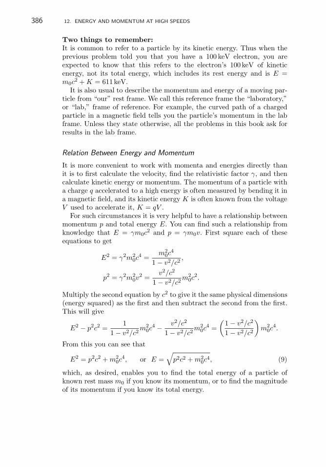
386 12. ENERGY AND MOMENTUM AT HIGH SPEEDS
Two things to remember:It is common to refer to a particle by its kinetic energy. Thus when theprevious problem told you that you have a 100 keV electron, you areexpected to know that this refers to the electron’s 100 keV of kineticenergy, not its total energy, which includes its rest energy and is E =m0c
2 + K = 611 keV.It is also usual to describe the momentum and energy of a moving par-
ticle from “our” rest frame. We call this reference frame the “laboratory,”or “lab,” frame of reference. For example, the curved path of a chargedparticle in a magnetic field tells you the particle’s momentum in the labframe. Unless they state otherwise, all the problems in this book ask forresults in the lab frame.
Relation Between Energy and Momentum
It is more convenient to work with momenta and energies directly thanit is to first calculate the velocity, find the relativistic factor γ, and thencalculate kinetic energy or momentum. The momentum of a particle witha charge q accelerated to a high energy is often measured by bending it ina magnetic field, and its kinetic energy K is often known from the voltageV used to accelerate it, K = qV .
For such circumstances it is very helpful to have a relationship betweenmomentum p and total energy E. You can find such a relationship fromknowledge that E = γm0c
2 and p = γm0v. First square each of theseequations to get
E2 = γ2m20c
4 =m2
0c4
1 − v2/c2,
p2 = γ2m20v
2 =v2/c2
1 − v2/c2m2
0c2.
Multiply the second equation by c2 to give it the same physical dimensions(energy squared) as the first and then subtract the second from the first.This will give
E2 − p2c2 =1
1 − v2/c2m2
0c4 − v2/c2
1 − v2/c2m2
0c4 =
(1 − v2/c2
1 − v2/c2
)
m20c
4.
From this you can see that
E2 = p2c2 + m20c
4, or E =√
p2c2 + m20c
4, (9)
which, as desired, enables you to find the total energy of a particle ofknown rest mass m0 if you know its momentum, or to find the magnitudeof its momentum if you know its total energy.

12.4. MASSES IN eV/c2; MOMENTA IN eV/c 387
� EXAMPLES
5. Find the momentum of a 100 keV electron (Exercise 7. p. 385)without finding γ. Use SI units.
The basic approach is to solve Eq. 9 for p. This gives
p =
√E2 − m2
0c4
c2.
Then you need to determine E, and to do this you need to know m0.From p. 635 of the appendix or from Exercise 17 in Chap. 9 you canfind that m0 = 9.11 × 10⁻³¹ kg for an electron. Then
E = K + m0c2 = qV + m0c
2
= 105 × 1.6 × 10−19 + 9.11 × 10−31 × 9 × 1016 = 9.80 × 10⁻¹⁴ J,
and
p =
√(9.8 × 10⁻¹⁴)2 − (8.20 × 10⁻¹⁴)2
9 × 1016= 1.79 × 10⁻²² kgm s−1.
This is pretty messy. An easier and more common way to work with Eand p is to abandon SI units and work with units based on the electronvolt (eV).
12.4 MASSES IN eV/c2; MOMENTA IN eV/c
Because units of electron volts are widely used in measurements of atomicparticles, it is convenient to express their masses and momenta in termsof electron volts.
� EXAMPLES
6. To see how to use these units, consider a 100 eV electron. Supposeyou want to find its velocity. It is of such low energy, i.e., v � c, thatyou can use
K =12m0v
2.
If you multiply the right-hand side by c2/c2, you will get
K =12m0c
2 v2
c2.

388 12. ENERGY AND MOMENTUM AT HIGH SPEEDS
In this form the convenience of the units becomes more evident.Knowing that m0c
2 for an electron is 511 keV, you get
100 =12· 511 × 103 · v2
c2,
which you can solve for v/c,
v
c=
√2 × 100
511 × 103= 1.98 × 10⁻²,
from which it follows that v = 5.94 × 10⁶ m/s.
The trick is to bundle together the right combination of m and c to geta quantity identifiable as an energy. Once you get used to it, using eV andsuppressing the factor c2 makes calculations easier and more informative.
� EXERCISES
8. What is the velocity of the 200 eV electrons used for measuringe/m in many undergraduate laboratories?
� EXAMPLES
7. You can also use this trick to find momentum. Suppose you want toknow the momentum of a 100 eV electron. Because this is a low-energyelectron, you can use the Newtonian approximation
K =p2
2m0.
Multiplying the right side by c2/c2 gives
K =p2c2
2m0c2,
which can be solved for pc:
pc =√
2Km0c2.
Now, if K is in eV and m0c2 is in eV, you will obtain pc in eV, so
pc =√
200 × 511 × 103 = 1.011 × 10⁴ eV,

12.4. MASSES IN eV/c2; MOMENTA IN eV/c 389
and you get p = 1.01 × 10⁴ eV/c, or, more compactly, p = 10.1 keV/c.The units eV/c are units of momentum commonly used in nuclear andparticle physics; they have dimensions M L T−1 like any other unit ofmomentum.
8. Find the momentum of a 1MeV electron.This electron has a kinetic energy twice its rest mass; therefore, it
is a high-energy electron for which you must use the relativisticallycorrect equations
E = K + m0c2 = 1 + 0.511MeV =
√(pc)2 + (0.511)2,
pc =√
(1.511)2 − (0.511)2 = 1.422MeV,
and thus p = 1.422MeV/c.
Momentum is frequently found by measuring the radius of curvatureR of a charged particle’s trajectory perpendicular to a uniform magneticfield B.Remember that a particle of charge e and momentum p will bendaccording to the relationship
p = eBR. Eq. 2, p. 205
To use eV units in this equation requires a little ingenuity. Notice thatif you multiply both sides by c, the dimensions of the equation becomethose of energy, i.e., pc has units of energy. At first glance it seems thatyou must evaluate eBRc using consistent SI units and obtain an answerin joules. This will certainly work, but notice that if you convert the rightside of the equation into electron volts, you divide by a conversion factorthat has a numerical value just equal to e. This means that if you dropthe factor of e and multiply B in tesla by R in meters and c in metersper second, your answer BRc will come out numerically in eV.
� EXAMPLES
9. What is the value of pc of an electron moving in a circle of radius1 cm perpendicular to a uniform magnetic field of 0.5 T? The answer(in eV) is BRc = 0.5× 0.01× 3× 108 = 1.5× 10⁶ eV = 1.5MeV. So themomentum of this electron is 1.5 MeV/c.
10. What uniform magnetic field B will bend an electron havingmomentum 1.422 MeV/c in a circle of radius R = 2.37 cm?

390 12. ENERGY AND MOMENTUM AT HIGH SPEEDS
Suppose you are unwilling to use eV units and cling to the SI. Atleast start with pc = qRBc. Then you need to convert the left side intojoules:
1.422 × 10⁶ [eV] × 1.602 × 10⁻¹⁹ [J/eV].
The right side will be
= 1.602 × 10⁻¹⁹[C] B[T] 0.0237[m] 3 × 10⁸[m/s]
= 1.139 × 10⁻¹²[J/T] B[T].
Now solve for B.But notice that the factor 1.602 × 10⁻¹⁹ appears on both sides of
the equation. On the left it is the conversion factor with units of J/eV;on the right it is the elementary charge with units of C (coulombs).Although the units are different, the numerical factor is the same, andwhen you divide both sides by 1.602 × 10⁻¹⁹ J/eV, you get
1.422 × 10⁶ eV = 0.0237 × 3 × 108 B [C·m·m/s·T·eV/J = eV]
where the equation F = qvB shows you that C·m·m/s·T is J (joule).So why not take this fact into account right from the start and skip
the SI units?
B =pc
Rc=
1.422 × 10⁶
0.0237 × 3 × 108= 0.20 T.
11. Suppose you want to know the radius of curvature with whichan electron with momentum of 10 keV/c bends in a magnetic field of10−3 T. Then
R =pc
Bc=
10 × 103
10−3 × 3 × 108= 3.37 × 10⁻² m = 3.37 cm.
� EXERCISES
9. A proton, (M0c2 = 938MeV) bends with a radius of curvature of
1m in a magnetic field of 0.1T. What are the momentum and thekinetic energy of that proton?

12.4. MASSES IN eV/c2; MOMENTA IN eV/c 391
� EXAMPLES
12. Here is a repeat of Example 5 using units of electron volts. Youare given that K = 100 keV, and you remember that for an electron,m0c
2 = 511 keV. The total energy E is the sum of the kinetic energyK and the rest energy, E = K + m0c
2, so E = 100 keV + 511 keV =611 keV.
Equation 9 tells you that 611 keV =√
(pc)2 + 5112, which you cansolve for pc:
6112 − 5112 = (pc)2,pc = 335 keV and p = 335 keV/c.
� EXERCISES
10. Show that the momentum of 335 keV/c obtained in Example 12 isthe same as the value of 1.79 × 10⁻²² kgm s−1 obtained in Example 5.
To work easily in eV you need to know the masses of the electron andthe proton in eV/c2. It may also be helpful to know the energy equivalentof one atomic mass unit, although for most purposes of this book youcan use the proton or hydrogen-atom mass instead. Energy equivalents ofthese and other useful masses are summarized in Table 12.2. From nowon work all energy and momentum problems in units of eV (or keV orMeV, etc.). The scale of these units is appropriate to atoms and smallerparticles.
TABLE 12.2 Some massesin energy units
Entity mc2 (MeV)
electron 0.511
H atom 938.8
proton 938.3
neutron 939.6
1 u 931.5

392 12. ENERGY AND MOMENTUM AT HIGH SPEEDS
12.5 WHEN CAN YOU APPROXIMATE?
In the preceding examples we told you when to use the Newtonian ap-proximation and when not to. What if you have to decide on your own?How can you tell whether to use K = p2/(2m0) or K = E − m0c
2? Herewe give you some guidance and some rules of thumb. Where the rulescome from is left for later courses in physics.
Nonrelativistic Approximations
You will often have to solve one or the other of two related problems:a. Given the momentum p, find the particle’s kinetic energy K.b. Given the kinetic energy K, find the particle’s momentum p.
When v/c is small, you can solve these problems using the approximateNewtonian equations:
K =p2c2
2m0c2,
or pc =√
2Km0c2.
As a measure of how good an approximation is, it is usual to use the“fractional difference” between the approximate and exact answers. (Frac-tional difference is often referred to as “fractional error.”) Therefore, givenan approximate value Ka and an exact value Ke, you want
Ka − Ke
Ke=
ΔK
Ke
to be small enough.How small is “small enough”? It depends on what you are doing with
your answer. If you are building a bridge or a particle accelerator, youwant a smaller fractional error than if you are doing physics homeworkproblems. For physics problems a fractional error of a few percent is oftensatisfactory. For the purposes of this book 2.5% is usually good enough.
� EXAMPLES
13. What is the fractional difference between 200 and 204? Between200 and 220?
The answer for the first case is (204 − 200)/200 = 0.02, or, as oneoften says, 2%. For the second case the fractional difference is 0.1, or10%.

12.5. WHEN CAN YOU APPROXIMATE? 393
The rest energy m0c2 is the key quantity for judging the accuracy of
the approximate equations. The precision of results is governed by theratio of K or pc to the rest energy m0c
2. You need to know m0c2 to judge
whether you can use approximate equations or if you must use the exactones.
For example, if the ratio of the particle’s kinetic energy to its restenergy, K/(m0c
2), is 0.1, a value of p calculated from√
2Km0 will deviatefrom the exact value by 2.5%. In other words, if you have a 51.1 keVelectron and you calculate its momentum non-relativistically, your answerwill differ from the exact answer by about 2.5%. For a proton the kineticenergy would have to be 94 MeV—10% of its rest energy—before thenon-relativistic equations would be in error by 2.5%.
� EXERCISES
11. What is the fractional error between the relativistic and non-relativistic calculations of momentum if the electron has a kineticenergy of 5.1 keV? 102 keV?
For a precision of 2.5% or better use the following rule of thumb:
• If K/(m0c2) < 0.1, you may use nonrelativistic equations to find
momentum from kinetic energy.
� EXERCISES
12. Suppose you had a 50MeV proton. Would the Newtonian equa-tions be good enough for calculating the proton’s momentum? Howmuch error would you make using the Newtonian equation?
If you know the momentum p and need to find the kinetic energy K,the nonrelativistic equation K = p2/(2m0) will give an answer that has afractional deviation from the relativistically exact answer that is ≤2.5%as long as pc/(m0c
2) <∼ 0.32. This means that for an electron with mo-mentum of 162 keV/c the nonrelativistic equation will give an answer thatis 2.5% low.
So if 2.5% is good enough precision, you have the following rule:
• To find K from p you may use nonrelativistic equations whenpc/(m0c
2) < 0.3.

394 12. ENERGY AND MOMENTUM AT HIGH SPEEDS
What if you know v and want to find K or p? When do you need touse the exact equations?
• To find K or p with an accuracy of 2.5% or better when you know v,you can use non-relativistic equations if v/c <∼ 0.2.
If you would rather remember only one rule of thumb, just rememberthe most restrictive:
• If the ratio of K/(m0c2) or pc/(m0c
2) or v/c is <0.1, you can usenonrelativistic equations with an error of less than 3%.
Ultrarelativistic Approximation
There is another extreme useful to know about. If the ratios of K or pcto the rest energy m0c
2 are greater than ≈40, you can simply ignore them0c
2 terms in Eq. 9. The connections of E, K, and pc become
K ≈ E ≈ pc.
This is called the “ultrarelativistic” approximation, and it is good tobetter than 2.5%.
� EXAMPLES
14. What is the momentum of a 1GeV electron? In this caseK/(m0c
2) is about 2000, so the particle is ultrarelativistic. Itsmomentum is 1GeV/c.
12.6 SUMMARY
In the study of a moving particle the quantities of most interest are itskinetic energy K, its closely related total energy E, and its momentum �p.
At high speeds, i.e., when v/c >∼ 0.1, the values of these quantities dif-fer appreciably from the predictions of Newtonian physics. This differentbehavior arises because inertial mass increases with a particle’s speed:
m =m0√
1 − v2/c2= γm0,

12.6. SUMMARY 395
where v is the particle’s speed, m0 is its mass in its rest frame of reference,and
γ ≡ 1√
1 − v2/c2.
The relativistically correct formulas connecting total energy E, kineticenergy K, momentum p, and mass m are
�p = m�v
E = mc2
E =√
m20c
4 + p2c2
K = E − m0c2.
The following relations are also useful:
v
c=
pc
E=√
1 − 1γ2
pc
m0c2=√
γ2 − 1
K
m0c2= γ − 1.
In the limit of v/c <∼ 0.1 the relativistically correct equations are verywell approximated by the nonrelativistic Newtonian equations �p = m0�v,K = p2/(2m0), and E = K+const. For many practical purposes whenv/c < 0.1 or K /(m0c
2) < 0.1 or pc/(m0c2) < 0.3, the Newtonian
equations are sufficiently accurate and easier to use.At speeds where v/c > 0.9997 or when K /(m0c
2) or pc/(m0c2) > 40,
you can neglect the m0c2 terms in the above equations. This is called the
ultrarelativistic approximation. Then K ≈ E and p ≈ E/c.In modern physics the units of energy are electron volts (eV) and their
SI multiples such as keV, MeV, GeV, TeV. They are used as units ofkinetic energy and potential energy. By extension they are used as unitsof mass, eV/c2, and units of momentum, eV/c. It is fairly common usageto say that the mass of a particle is so many eV, e. g., the mass of aproton is 938MeV. You are supposed to know that this number includesthe factor of c2.
You need to know the values of the speed of light c = 3 × 10⁸ m/s andthe rest masses of the electron (511 keV/c2) and the proton (938MeV/c2).

396 12. ENERGY AND MOMENTUM AT HIGH SPEEDS
PROBLEMS
1. A 9.38MeV proton enters a magnetic field and is bent in a circle ofradius r = 0.2 m.
a. Is this a relativistic, nonrelativistic, or ultrarelativistic proton?How do you know?
b. What is the extra mass of this proton arising from its motion? Giveyour answer in the appropriate multiple of eV.
2. Suppose you have an electron traveling with a velocity such thatγ = 3.
a. What is its kinetic energy?b. What is its momentum?c. What would be its radius of curvature in a magnetic field of B =
0.1 T?d. What is its velocity?
3. Suppose a stick and S′ are moving past S at a velocity such that γ = 3.If the stick has a mass of 1 kg when it is at rest,
a. What does S′ measure its mass to be?b. What does S measure its mass to be?
4. What is the kinetic energy of the stick in the previous questiona. as measured by S′?b. as measured by S?
5. a. We know that E = mc2 = γm0c2. Use this relation to give a
relativistically correct definition of kinetic energy K. Explain whythis is a sensible definition.
b. Show by a series expansion that for v/c � 1 your above definition iswell approximated by the usual classical formula for kinetic energy.
c. An electron is accelerated through a potential difference of 10V.What is the relativistic increase in its mass? Explain.
6. A stationary particle having a rest mass energy of 1400MeV disin-tegrates into two particles called “pions,” a π+ and a π−, that travel inopposite directions, as shown schematically in Fig. 12.4. Each of the pionshas a rest-mass energy of 140MeV.

PROBLEMS 397
π– π+
M(a)
(b)
FIGURE 12.4 A particle disintegrates into two pions (Problem 6).
a. Find the kinetic energy, in appropriate units, of each outgoingparticle.
b. What is the value of γ (“gamma”) for either pion?c. When the pions are at rest, they have a lifetime of 0.28 ns. Accord-
ing to an observer in the laboratory, what is the lifetime of themoving pions (in ns)?
7. A positively charged K meson—a K+ kaon—with a momentum p =8.2 GeV/c enters a bubble chamber (a device in which charged particlesleave visible tracks) and decays into two pions: K+ → π+ + π0. The restmass of the kaon is 494 MeV/c2 and that of each pion is 140 MeV/c2.
a. Calculate the total energy of the kaon. Do this exactly.b. What is the value of γ? Find the speed of the kaon in terms of c.
Is the ultra-relativistic approximation valid for this kaon?c. The K+ has an average lifetime of 12.4 ns in its rest frame.
What lifetime would you measure in the rest frame of the bubblechamber?
d. In the rest frame of the bubble chamber how far (on average) woulda kaon travel before decaying? What distance would this be in thekaon’s frame of reference?
e. Suppose that the two pions have the same kinetic energy. Whatwould that kinetic energy be? What is the value of γ for eitherpion? What is the magnitude of the momentum of either pion?
f. Assuming that the paths of the pions make equal angles θ, find θ(Fig. 12.5).
8. The rest mass energies of a proton and an electron are 938MeV and0.511MeV, respectively. Calculate the total energy of each of the followingparticles:

398 12. ENERGY AND MOMENTUM AT HIGH SPEEDS
0
+
K+
FIGURE 12.5 A positively charged kaon traveling through a bubble chamber dis-integrates into two pions. This diagram shows their momenta before and after thedisintegration (Problem 7(f)).
e e–
(a) (b)
FIGURE 12.6 An electron and a positron collide and become two photons (Problem 9).
a. a 10MeV proton.b. an electron with γ = 1000.c. a 500MeV electron.Are any of these particles “ultrarelativistic?” If so, which one(s)?
9. There is a particle with the same mass as the electron but positivelycharged. It is called a “positron.” The “Tristan” particle accelerator atTsukuba, Japan, accelerates both electrons and positrons to energies of25GeV and then directs them into head-on collisions in which they an-nihilate one another; i.e., they turn into a pair of high-energy photons,as illustrated in Fig. 12.6. Give your answers to the following questionsin eV.
a. Are these particles nonrelativistic, relativistic, or ultrarelativistic?Justify your answer briefly.
b. Find the momentum of a 25GeV electron.c. Suppose a single new particle is formed in the collision of a positron
and an electron in this machine. Determine the momentum, kineticenergy, and rest mass of such a particle.
d. If instead of forming a new particle, all of the electron and positronenergy is used to produce two photons of equal wavelength travelingin opposite directions (See Fig. 12.6b):

PROBLEMS 399
i. Estimate the wavelength of each photon.ii. Why are two photons, rather than one, generated? (Hint:
consider the conservation laws.)
10. What magnetic field will bend a 1.02MeV electron in a circle witha radius of 1m?
11. What magnetic field will bend a 1.02MeV proton in a circle with aradius of 1m?
12. What magnetic field is required to bend a 1GeV electron in a circle10m in radius?
13. What magnetic field is required to bend a 1GeV proton in a circle10m in radius?
14. What is the velocity of a 1.02MeV electron? Express your answeras a fraction of the speed of light c.
15. An electron in a magnetic field of 1 kG (0.1 T) is bent in an arc witha radius of 1m. What is the electron’s kinetic energy?
16. For each of the preceding six questions, justify using the nonrela-tivistic approximation, the ultrarelativistic approximation, or the exactrelativistic equations.
17. The rest mass energies of the electron and proton are respectively511 keV and 938MeV. For the cases i–iv below:
a. Determine whether the particles are nonrelativistic or ultrarela-tivistic. Justify your answer.
b. Calculate the kinetic energies (in eV) for each case, using the ap-propriate approximate formulas in each case and also the exactrelativistic formulas.i. An electron with a momentum of 10 keV/c.ii. An electron with a momentum of 10GeV/c.iii. A proton with γ = 50.iv. A proton with v/c = 0.05.
18. A proton and an antiproton each traveling with a momentum of10GeV/c collide head-on in a high-energy physics experiment. The proton

400 12. ENERGY AND MOMENTUM AT HIGH SPEEDS
and antiproton have equal rest masses (938MeV/c2), and charges ofopposite sign but equal magnitude.
a. What is the total energy before the collision?b. If they collide to form a new particle, determine its momentum,
charge, and rest-mass energy.c. The new particle is unstable and decays into two pions, π+ and
π−, both of which have rest masses of 140MeV/c2, and oppositebut equal-magnitude charges. Find the resulting kinetic energy ofeach pion.
19. What is the speed, relative to the speed of light, of an electron withkinetic energy equal in value to its rest mass?
20. A typical nuclear reactor produces about 2.5 × 10⁹ J of thermalenergy in 1 s.
a. What mass does this energy correspond to?b. If 200MeV of energy is released per fission, how many fissions occur
per second in this nuclear reactor?c. What fraction of the mass of a 235U nucleus is converted into
thermal and radiant energy when it undergoes fission?
21. Find the energy released in the deuterium–deuterium fusion reaction2H + 2H → 3He + 1n.
The rest masses of 2H, 3He, and the neutron 1n are 2.014102 u, 3.016029 u,and 1.008665 u respectively.
22. Consider the decay 55Cr → 55Mn + e−, where e is an electron.The nuclei 55Cr and 55Mn have masses of 54.9279 u and 54.9244 u, respec-tively. Calculate the mass difference of the reaction. What is the maximumkinetic energy of the emitted electron?
23. In the electron–positron collider at Cornell University, electrons andpositrons acquire oppositely directed momenta of 4.0GeV/c before theycollide head-on.
a. Suppose that after the two particles collide they unite to form anew particle at rest. What is the rest mass of the new particle?
b. Suppose the new particle decays into a proton and an antiprotonthat move in opposite directions. What is the kinetic energy ofeither particle?
c. What is the velocity relative to the speed of light, and what is themomentum of either particle?

1313C H A P T E R
The Granularityof Light
13.1 INTRODUCTION
The discovery of the electron swiftly led to better understanding of thenature of matter. This in turn led to a revolution in the understandingof the nature of light. The most surprising outcome was the discoverythat under many circumstances light and other forms of electromagneticradiation behave like particles instead of waves. There are two outstand-ing examples of light behaving like particles. One example is called “thephotoelectric effect” and the other “the Compton effect.”
13.2 THE PHOTOELECTRIC EFFECT
Discovery of the Photoelectric Effect
In 1887 Heinrich Hertz showed that, as Maxwell had predicted, oscillatingelectric and magnetic fields produce radiation that travels with speed c.In effect, Hertz discovered electromagnetic radiation in the form of radiowaves and provided convincing evidence that visible light is just a shorterwavelength form of such radiation. While doing this work, Hertz alsodiscovered the photoelectric effect.
On one side of a room he generated radio waves by means of a high-frequency current sparking across a gap. The resulting waves crossed theroom and induced sparking in a properly adjusted detecting apparatus.He observed that this induced spark was much larger when the metaltips of the spark gap were illuminated with light from the sparks of thegenerator across the room. When the light from the generating sparks waspassed through glass before reaching the detecting spark gap, the spark
C.H. Holbrow et al., Modern Introductory Physics, Second Edition, 401DOI 10.1007/978-0-387-79080-0 13, c© Springer Science+Business Media, LLC 1999, 2010

402 13. THE GRANULARITY OF LIGHT
became smaller, but when the light came through a quartz plate, theinduced spark remained large. Hertz knew that glass absorbs ultravioletlight and that quartz does not, so he concluded that it was ultravioletlight causing the spark in the detector to become larger.1
In 1888, shortly after Hertz’s observations, Hallwachs found that anegatively charged zinc plate would discharge when illuminated with ul-traviolet light, while a positively charged plate would not.2 This emissionof negative electricity from the metal when illuminated with light of suit-ably short wavelength is called the “photoelectric effect.” In 1889 Elsterand Geitel showed that the photoelectric effect could be produced usingvisible light on metals that were amalgams of mercury with the alkalimetals cesium, sodium, and potassium, as well as with zinc.
As you have seen, it was another decade before techniques were devel-oped that gave reliable measurements on charged particles such as theelectron. Understanding of the photoelectric effect did not progress muchuntil it was possible to measure directly the actual charges released whenlight struck these metals.
Properties of the Effect
In 1899, two years after discovering the electron, J.J. Thomson, inEngland, and Philipp Lenard, in Germany, measured the charge-to-massratio q/m of the negative charges emitted in the photoelectric effect. Theyfound q/m to be similar to the ratio already measured by Thomson forcathode rays, i.e., electrons, and concluded that the photoelectric chargesmust also be electrons.
Figure 13.1 is a diagram of the apparatus Lenard used to study theelectrons emitted when light strikes a metal. Electrons produced usinglight are often called “photoelectrons.” He used the apparatus both tomeasure the q/m ratio of the photoelectrons and to learn some thingsabout their energy. The apparatus is in some ways like the one used tomeasure e/m. Here the cathode rays are produced when ultraviolet lightfrom S shines through the window Q and strikes the cathode C, releasingcharges. The flow of charges initiated by the light is often called the“photocurrent.” The charges emitted at the cathode C have some initialenergy Ki, and they acquire more kinetic energy by passing through apotential difference V maintained between C and A. The charges thatpass through the hole in A proceed on with kinetic energy
12mv2 = e V + Ki.
1Heinrich Hertz, Electric Waves, MacMillan & Co., London and New York, 1893.2W. Hallwachs, Ann. d. Phys. 33, 301 (1888).

13.2. THE PHOTOELECTRIC EFFECT 403
Ipc
Ipc
Electron currentmeter 2
Electron currentmeter 1
P2
P1
A
B
C
Q S
FIGURE 13.1 Lenard’s apparatus for measuring q/m and Kmax of photoelectrons. Thedashed oval curve surrounds the region where a magnetic field is applied perpendicularto the plane of the page.
In Fig. 13.1 the dashed oval shows where a uniform magnetic field Bcan be applied directed out of the plane of the paper. When the field isoff, charges coming through the hole A strike the anode P1, and there is aphotocurrent in meter 1; when the field is on and properly adjusted, thecharged particles bend in a circle of radius R onto P2. Then in meter 2there is a photocurrent that becomes maximum for some value of B. Ris measured from the geometry of the apparatus. If V is large enough sothat eV � Ki, you can combine the energy equation with mv = eBRand show that
e
m=
2VB2R2
. (1)
Equation 1 is the same as Eq. 8 derived in Chap. 9 (p. 241). Lenardmeasured q/m to be 1.2 × 10¹¹ C/kg and concluded that the emittedcharges were electrons.
� EXERCISES
1. How does this value compare with the value of e/m obtained byThomson as described in Chap. 9? With the currently accepted value?Why do you suppose people measuring values of e/m that differed by≈ 50% or more all agreed that they were seeing the same particle?

404 13. THE GRANULARITY OF LIGHT
Lenard observed that some photocurrent flowed even when the voltageof C was made positive—up to 2.1V—relative to A. He realized that thismeant that some of the electrons were emitted with enough energy toescape the attraction of plate C when it was positively charged. Whenthe voltage on C became too positive, that is, greater than 2.1V, no morecharge flowed. This result meant that the photoelectrons had a maximumkinetic energy of 2.1 eV.
Lenard’s most surprising observation was that an increase in the in-tensity of the incident light led to a proportional increase in the numberof photoelectrons but did not change their maximum energy! Only whenLenard varied the frequency of the incident light did the maximum en-ergy change. Later, more refined experiments confirmed these resultsand showed that the higher the frequency of incident light, the higherwould be the maximum energy of the emitted electrons. In Fig. 13.2schematic plots of photocurrent Ipc vs. the cathode voltage V show theeffects of changing the intensity and also the frequency of the illuminatinglight.
(a)
(b)
Ipc
I1
I2
I3
f2
f1
f3f1<f2<f3
I1<I2<I3
Ipc
5 –5 –10 –15
5 –5 –10 –15
V (volts)
V (volts)V01V02
V0
FIGURE 13.2 Photocurrent Ipc vs. cathode voltage V (a) for different intensities I1,I2, I3 and (b) for different frequencies f1, f2, and f3 of incident light. Increases inintensity increase the photocurrent but do not change the voltage V0 corresponding toKmax; only increases in frequency increase Kmax.

13.2. THE PHOTOELECTRIC EFFECT 405
� EXERCISES
2. When you shine ultraviolet light on a zinc plate connected to acharged electroscope, it discharges when negatively charged but notwhen positively charged. Use the discovery that the charges emitted inthe photoelectric effect are electrons to explain these observations.
There was another surprising property of the photoelectrons. They be-gan to flow as soon as the cathode was illuminated; there was no timedelay between the arrival of the light and the emission of photoelectrons.This was unexpected for the same reason that it was a surprise to findthat the maximum energy of the electrons did not depend on the intensityof light. Recall that the model of light as a wave implies that light emittedfrom a source spreads out through space and, like a water or sound wave,becomes ever weaker the farther it is from its source.
The fact that the intensity of light from a point source of light decreasesas 1/r2 as you move a distance r from the source follows from the geometryof a sphere. As an example, consider light from the Sun, which emits atotal of W0 = 3.9 × 1026 J/s of electromagnetic radiation (mostly in thevisible spectrum). By the time this radiation reaches Earth 1.5 × 10¹¹ mfrom the Sun, its energy is spread over a sphere of area
4πr2 = 4π(1.5 × 10¹¹)2 = 2.8 × 10²³ m2,
so that measurements of the solar energy incident at the top of Earth’satmosphere show that the amount of energy incident per second per unitarea (the definition of intensity) is
3.9 × 1026
2.8 × 1023= 1390 J s−1 m−2.
As the sunlight travels further and further, the area of the surroundingsphere grows as r2, so the energy is spread over a larger area, and itsintensity drops as 1/r2. Thus, at the planet Jupiter, which is 5.2 timesfurther from the Sun than Earth, the intensity of sunlight striking theouter atmosphere of Jupiter is
1390(5.2)2
= 51J s−1 m−2.
To see what is surprising about the fact that photoelectrons are emittedas soon as light strikes the metal, consider how quickly an atom couldaccumulate energy from a wave and get enough to eject the photoelectron.Assume that the photoelectric effect is to be produced with a narrow bandof frequencies of sunlight, say between 700.0THz and 700.3THz (a deep

406 13. THE GRANULARITY OF LIGHT
blue light). This range contains about 7× 10⁻⁵ of the total energy in thesunlight, and only half of that reaches the ground. Therefore, the intensityof the light for our experiment might be in the range of
3.5 × 10−5 × 1390 = 0.049 J s−1 m−2.
A beam of light with this intensity is very easy to see.The research of Lenard and others showed that it takes different
amounts of work to release an electron from different metals. Supposeyou have a metal which requires about 2.9 eV to release an electron. Howlong do you expect it to take light with an intensity of 0.049 J m−2 s−1 tosupply the necessary 2.9 eV to an atom? If the energy of light is spreadsmoothly over space, then the rate that energy is supplied to an atom isWa = Iπr2, where πr2 is the cross-sectional area of the atom of radius rand I is the intensity of the light. For an atom with a typical radius of0.2 nm,
Wa = 0.049π(0.2 × 10⁻⁹)2 = 6.2 × 10⁻²¹ J s−1,
or
Wa = 0.038 eV s−1.
This result tells you that if this light were arriving as a wave spreadingout from its source, it would take about 76 seconds before the incidentlight could supply the 2.9 eV the atom needs to release an electron.
� EXERCISES
3. Complete the calculation to show that it would take about 76seconds, or well over a minute, to release one electron under theassumptions discussed above.
Einstein’s Explanation: E = hf
The essentially instantaneous emission of an electron was an extraordinaryresult, totally at odds with classical physics. Sir William Bragg describedthe strangeness of the effect very well when he said:
It is as if one dropped a plank into the sea from a height of 100 feet,and found that the spreading ripple was able, after travelling 1000miles and becoming infinitesimal in comparison with its originalamount, to act on a wooden ship in such a way that a plank ofthat ship flew out of its place to a height of 100 feet.

13.2. THE PHOTOELECTRIC EFFECT 407
Think about this image. When you understand it, you will understandwhy the photoelectric effect was so remarkable. No matter how low theintensity of the light, energy was either delivered instantly and completelyto the atom or not at all.
The idea of the continuous, smooth spreading of electromagnetic energymust simply be wrong. Einstein was the first to accept that possibility.He generalized an idea of Max Planck and asserted that light (both thevisible part and all other forms of electromagnetic energy) carries energyin indivisible amounts, or “quanta.” Each quantum of light of frequency fhas an energy of hf , where h is a constant known as “Planck’s constant”with the value 6.63 × 10⁻³⁴ J s.
� EXERCISES
4. Find the value of h in eV s, units that will often be useful in thisbook.
Your answer h = 4.14 × 10⁻¹⁵ eV s means that light of frequency700THz consists of many packets, or quanta, each carrying an energyof 700 × 1012 × 4.14 × 10−15 = 2.9 eV.
If that is the case, said Einstein, then we can understand that eachelectron is emitted immediately following the absorption of a single quan-tum of light. It is then evident that reducing the intensity of the lightjust reduces the number of quanta, but not the time it takes a particularquantum to be absorbed and produce the emission of an electron.
Also, it is clear from conservation of energy that no electron can beejected from the metal with more energy than the quantum of lightbrought to it in the first place. In fact, experimental evidence showed thateven the electrons emitted with maximum energy did not have the fullenergy supplied by the “photon,” as a quantum of light is often called.Einstein understood that it would take some energy to break the elec-tron loose from the surface; this energy is called the “work function” ofthe metal and is often represented by the lowercase Greek letter phi, φ.Einstein summarized his ideas by a simple statement of the conservationof energy,
Kmax =12
mv2max = hf − φ, (2)
which says that the maximum kinetic energy a photoelectron can have isthe amount carried in by the photon less the energy used to break theelectron loose.

408 13. THE GRANULARITY OF LIGHT
Experimental Verification of Einstein’s Equation
Precise experimental verification of Einstein’s equation was difficult forpractical reasons. The energies of emitted photoelectrons depend sen-sitively on the state of the metallic surface. Metal surfaces are alwayscoated with oxide layers, and surfaces usually have thin films of oil orother contaminants. It is difficult to prepare surfaces so that from exper-iment to experiment the surface is in the same state. Millikan3 partiallysolved this problem by installing a machine tool in an evacuated box andusing it to shave off a thin layer of metal to make a surface in a well-defined state of cleanliness. Even then, it was hard to get reproducibleresults because a vacuum is never perfect, and a surface will quickly ox-idize and pick up contaminants after it is cleaned. Millikan’s results wereconvincing because he found an independent way to determine φ, andthen he showed that there was a way to prepare the surface so that φremained unchanged over several weeks. The surface was quite dirty, butit was reproducibly dirty. That was enough to make his measurementsmeaningful.4
Millikan measured the maximum kinetic energy of photoelectrons emit-ted from sodium metal illuminated with various wavelengths of light. Hisapparatus, shown schematically in Fig. 13.3, was entirely contained invacuum. The wheel W would rotate one of the three metal cylinders—one of sodium metal, one of lithium, and one of potassium—under theknife K, which then shaved off a layer of metal to clean the surface. Thecylinder was then rotated around to face a window O through which camea beam of monochromatic light.
The energy of the electrons was determined by measuring the photocur-rent versus the electric potential difference between the sodium metal andthe wire mesh B and collector C. This electric potential difference is thecathode voltage, V , and when it is positive, it impedes the flow of theelectrons from the sodium cathode to the mesh and the anode. The cath-ode voltage was varied until the photocurrent vanished. The value of V0 atwhich electrons just cease to flow corresponds to the maximum electronenergy, i.e., Kmax, because
12mv2
max = eV0
3R.A. Millikan, A direct photoelectric determination of Planck’s “h,” Phys. Rev. 7, 355–388(1916); Einstein’s photoelectric equation and contact electromotive force, Phys. Rev. 7 (Secondseries), 18–32 (1916).4This is another situation where inadequate vacuum resulting from the limits of the technol-ogy of the day caused much confusion that was cleared up only by ingenious design of theexperiment and by carrying it out very carefully.

13.2. THE PHOTOELECTRIC EFFECT 409
light
alkalimetal
rotating knife
FIGURE 13.3 Diagram of Millikan’s photoelectric effect apparatus. Taken with per-mission from R.A. Millikan, Phys. Rev. Vol. 7, 355–388 (1916), c©1916 The AmericanPhysics Society.
TABLE 13.1 Experimental values of photocurrent Ipc vs. cathode voltage V for
sodium illuminated with six different wavelengths of lighta
546.1 nm 433.9 nm 404.7 nm 365.0 nm 312.6 nm 253.5 nm
V0
(V)Ipc
(mmdefl)
V0
(V)Ipc
(mmdefl)
V0
(V)Ipc
(mmdefl)
V0
(V)Ipc
(mmdefl)
V0
(V)Ipc
(mmdefl)
V0
(V)Ipc
(mmdefl)
0.253 28 0.829 44 0.934 82 1.353 67.5 1.929 52 2.452 68
0.305 14 0.889 20 0.986 55 1.405 36 1.981 29 2.568 38
0.358 7 0.934 10 1.039 36 1.458 19 2.034 12 2.672 26
0.410 3 0.986 4 1.091 24 1.510 11 2.086 5 2.777 16.5
1.143 10 1.562 4 2.882 8
1.196 3
0.46 V 1.03 V 1.21 V 1.59 V 2.13 V 3.03 Va Adapted from Millikan, A direct photoelectric determination of Planck’s “h,” Phys. Rev. 7355–388 (1916). Three entries from his table have been corrected to agree with his graphs, andevery entry has been corrected for 2.51V of contact potential. The bottom row of the table
contains the values of V0 at which Ipc goes to zero as determined by Millikan’s extrapolation.The current was read as millimeters of deflection (mm defl) on the scale of an electrometer.
(after correcting for the voltage produced by the battery action of thedifferent metals of which the apparatus was made).
Millikan made careful measurements using several different wavelengthsof light on lithium, sodium and potassium. His data for sodium are givenin Table 13.1. These data illustrate an important difficulty of experi-

410 13. THE GRANULARITY OF LIGHT
Stopping voltage (V)
Photo
curr
ent
(mm
def
lect
ion)
0.20.30.40.5
60
50
40
30
20
10
0
546.1 nm
FIGURE 13.4 Use of extrapolation to determine the cathode voltage V0 at which thephotocurrent Ipc → 0 for 546.1 nm light on sodium.
ments that try to determine the point at which a quantity becomes zero.Accurate location of this point is usually difficult because there are alwaysa few electrons around from stray light or other sources, and they obscurethe zero point. The answer is found by measuring V at points where thephotocurrent is not zero and then determining V0 by extrapolation, asshown in Fig. 13.4. There is always some guesswork in such extrapolationbecause the data points that will best inform you about where the zeropoint is are also the least reliable data points because they are small andmore like the obscuring background. Millikan’s extrapolated values aregiven in the last row of Table 13.1.
� EXERCISES
5. Try some extrapolation yourself. Find the zero points for 433.9 and404.7 nm light. How well do your values agree with Millikan’s?
� EXAMPLES
1. How can you find the work function from Millikan’s data? For546.1 nm light the cathode voltage at which the photocurrent be-comes zero (found by extrapolation) is 0.46V; therefore, the maximumenergy Kmax of electrons from the photoelectric effect induced with

13.2. THE PHOTOELECTRIC EFFECT 411
TABLE 13.2 Work functions of somemetals
Metal Work function (eV)
silver 4.73
aluminum 4.20
calcium 2.7
cesium 1.9
potassium 1.76–2.25
sodium 1.90–2.46
rubidium 1.8–2.2
copper 4.1–4.5
iron 4.72
nickel 5.01
platinum 6.30
this light is 0.46 eV. Because the energy of a 546.1 nm photon is1240/546.1 = 2.27 eV, the work function must be 2.27−0.46 = 1.81 eV.
� EXERCISES
6. Calculate the work function using Millikan’s data for λ = 433.9,404.7, 365.0, 312.6, and 253.5 nm. How do your answers compare amongthemselves? With the value(s) given in Table 13.2?
7. Consider Eq. 2. In a plot of Kmax of the photoelectrons vs. thefrequency of the incident light, what functional dependence and shapeof curve do you expect? What should be the slope?
8. Use Millikan’s data to determine values of Kmax. Plot them versusfrequency. Do the slope and intercept agree with what you would expectfrom Eq. 2? Your results should show excellent agreement betweenMillikan’s measurements and Einstein’s predictions.
So Einstein was right. Electromagnetic radiation has its energy in pack-ets. It is quantized. Light of frequency f has a smallest indivisible amountof energy hf . Light possesses a kind of atomicity; it consists of photons.

412 13. THE GRANULARITY OF LIGHT
� EXAMPLES
2. What is the maximum velocity of photoelectrons emitted when250 nm light strikes a clean aluminum plate?
Notice that in addition to answering the question, this example in-troduces you to an efficient way to calculate a photon energy hc =1240 eV nm because
hc = 4.136 × 10⁻¹⁵ eV s × 2.9979 × 10⁸ m s−1 = 1240 eV nm.
To find the maximum possible velocity, find hf and φ and then useconservation of energy Eq. 2 to calculate the maximum possible kineticenergy of an emitted electron. For Al, φ = 4.20 eV (see Table 13.2).For 250 nm light,
hf =hc
λ=
1240250
= 4.96 eV.
(Learn to use this way to connect hf and λ; it permits you to use photonenergies given in eV and wavelengths given in nm without having toconvert them to SI units.)
From conservation of energy12mv2
max = 4.96 − 4.20 = 0.76 eV.
To find vmax rewrite the above to have mass in units of eV/c2,
12mv2
max =12mc2
(vmax
c
)2= 0.76 eV,
which you can solve for vmax/c:
vmax
c=
√2 × .76mc2
=
√1.52
511 × 103= 1.73 × 10⁻³,
so
vmax = 1.73 × 10⁻³c = 5.2 × 10⁵ m s−1.
13.3 PHOTOMULTIPLIER TUBES: AN APPLICATIONOF THE PHOTOELECTRIC EFFECT
Within five years of its discovery the photoelectric effect was used tomeasure ultraviolet radiation from the Sun. Since then, many instrumentsfor detecting and measuring light have been based on the photoelectric

13.3. PHOTOMULTIPLIER TUBES 413
effect. One of these, the photomultiplier tube, is widely used in industryand in research. This device can detect individual photons; it can directlydemonstrate the granularity of light.
How the Photomultiplier Tube Works
The photomultiplier uses two different effects: the photoelectric effect andelectron multiplication. When a photon strikes a surface coated with amaterial with low work function, an electron is sometimes emitted. Thisis just the photoelectric effect, and it represents a conversion of lightenergy into an electric current, i.e., into the motion of an electric charge.
A single electron charge is difficult to detect, and it is desirable toamplify it. This is done by placing nearby a second surface at a voltagepositive with respect to the first. The electron emitted from the firstsurface is then accelerated toward the second surface. It gains enoughenergy so that when it strikes the second surface, it causes the emissionof several electrons. This process is called “secondary emission,” and itmultiplies the electrons.
The multiplication can be repeated by placing a third surface nearbywith a voltage positive relative to the second. Then if the surfaces areproperly shaped and arranged, the electric fields associated with the volt-age difference between them will direct all the electrons emitted from thesecond surface onto the third one. Each impacting electron causes theemission of several electrons, and the multiplication repeats, as shown inFig. 13.5.
Parts of a Photomultiplier Tube
The surfaces that emit and collect electrons are called the “electrodes”of the photomultiplier. The first electrode, where the photoelectric effectoccurs, is called the “photocathode.” The last electrode, where the mul-tiplied electrons emerge as a current, is called the “anode.” (You can seethat these names are adapted from Faraday’s names for the parts of anelectrolytic cell.) The electrodes between the photocathode and the anodeare called “dynodes.” It is at the dynodes that electron multiplicationoccurs.
An electron from the photocathode passing down a string of dynodeseach 100 volts higher than the preceding one can give rise to an overallamplification from 103 to 108. Exactly what amplification occurs dependsupon the voltage between the dynodes, the material of which the dynodesare made, the total number of dynodes in the string, and the particulargeometric arrangement of the dynodes. Figure 13.5 shows schematicallyone possible arrangement of photomultiplier electrodes.

414 13. THE GRANULARITY OF LIGHT
e-
Window
Photo-cathode
Light
Focusingelectrode
Secondaryelectrons
(Anode)Last dynode Vacuum
(10–4 Pa)
Electronmultiplier(dynode array)
FIGURE 13.5 Schematic diagram of electrodes and electron multiplication in aphotomultiplier tube.
� EXERCISES
9. What is the overall amplification of a photomultiplier tube thathas nine dynodes and an electron multiplication factor of six at eachdynode?
Among the many practical considerations in the design of photomul-tiplier tubes is finding photocathode materials that can emit an electronfor long wavelengths of light, i.e., materials with especially low work func-tions. Even with enough energy, not every photon causes the emission ofan electron. Therefore, we look for materials in which production of a pho-toelectron is both energetically possible and maximally probable. Somealkali metals produce only one photoelectron for every 1000 incident pho-tons, while some mixtures of alkalis, e. g., the multialkali Na K Sb Cs,can produce as many as 300 electrons for every 1000 photons. This ratiois very important and is called the “quantum efficiency.” The two ex-amples here illustrate quantum efficiencies of 0.1% and 30%. A quantumefficiency of 30% is about as large as you can get with visible light.

13.4. SUMMARY 415
Scintillation Counting of Radioactivity: A Useful Application
When an energetic charged particle or a high-energy photon strikes a pieceof matter, it may impart all or some of its energy to an electron in thematter. The electron’s energy will often go to make a small flash of light,and if the crystal is transparent, as is, for example, sodium iodide dopedwith thallium, NaI(Tl), this flash can be detected. A small flash of light iscalled a “scintillation.” By detecting and counting the scintillations, onedetects and counts incident particles. Even better, the size of the lightflash is proportional to the amount of energy the particle or incident pho-ton leaves in the crystal. By comparing the amounts of light in differentscintillations one compares the energies of incident particles. The scintil-lator converts the energy of an invisible charged particle or high-energyphoton into a pulse of low-energy visible photons.
The photomultiplier tube is very effective for counting such scintil-lations. The tube (see Fig. 13.5) is arranged to view the crystal intowhich the incident particles are directed. Photons from a scintillationstrike the photocathode of the photomultiplier, which emits a tiny pulseof electrons. These are then amplified, and there appears at the anode anelectrical pulse signaling the presence of an incident particle; the pulsesize is proportional to the energy deposited in the crystal by the detectedparticle.
13.4 SUMMARY
Electromagnetic radiation comes in discrete packets of energy called pho-tons. For radiation of frequency f , the energy of a single photon is hf ,where h is an experimentally determined constant called “Planck’s con-stant.” Its value is 4.14×10⁻¹⁵ eV s, but it is especially useful to rememberthat hc = 1240 eVnm.
Einstein’s idea of the granularity of light explained the photoelectriceffect. He showed that if light came in discrete quanta, then radiation offrequency f upon being absorbed into a surface could release electronswith a maximum kinetic energy
12mv2
max = hf − φ,
where φ is the work function of the surface. Millikan’s experimentalmeasurements verified Einstein’s predictions.

416 13. THE GRANULARITY OF LIGHT
PROBLEMS
1. You have been put in the basement of a building from which you canescape only by riding up to the ground floor on a coin operated elevatorthat requires $2. Someone passes you a $5 bill through the bars of thebasement window. Fortunately, the elevator’s money slot makes change.There is also in the elevator a video game that requires $0.50 per game.
a. What is the maximum amount of money that you can have leftwhen you reach the ground floor?
b. What is the minimum amount of money that you can have leftwhen you reach the ground floor?
c. How is this situation analogous to the photoelectric effect?
2. Light is directed onto a metal surface for which the work functionis 2 eV. If the light’s frequency f is such that hf = 5eV, what is themaximum energy with which an electron can be emitted from the surface?
3. Light with wavelength of λ = 450 nm shines on a cesium sample, and aphotoelectric current flows. With a retarding voltage of 0.85 V the currentgoes to zero.
a. What is the maximum kinetic energy of electrons emitted by thecesium?
b. Find the work function for cesium.
4. A marvelous new metal, phonium, is found to have a work functionof 1 eV.
a. If a photon of 3 eV energy strikes phonium and causes the emissionof an electron, what is the maximum kinetic energy that electroncan have?
b. Light of wavelength 620 nm strikes phonium. What is the maximumenergy of electrons emitted by the photoelectric effect under thesecircumstances?
c. What are two features of the photoelectric effect that supportthe idea that light energy comes as multiples of some smallest,indivisible packet?
d. What is the highest energy photon that can be produced when elec-trons that have been accelerated through 40 kV stop by a suddencollision with a tungsten anode?

PROBLEMS 417
I(nA)
12 –1 –2 –3 V (volts)
V A
Cathode Anode
620 nm
FIGURE 13.6 Photocurrent vs. cathode voltage (Problem 5).
5. The schematic diagram in Fig. 13.6 shows an apparatus for studyingthe photoelectric (PE) effect. When light of wavelength 620 nm shines onthe cathode, electrons are emitted. The current I of electrons that reachthe anode across a potential difference V is measured on the ammeter A.(In what follows neglect any contact potential.)
a. What did Einstein conclude about the nature of light in order toexplain the various features of the PE effect?
b. As the voltage V is varied from negative to positive values, thecurrent I changes as shown in the graph above.i. Why is the current of emitted electrons not zero when V < 0?ii. What is the maximum kinetic energy of an electron emitted
when 620 nm light strikes the cathode?c. On the same graph, sketch how the current I varies as V is changed
when the cathode is illuminated with 310 nm light.d. What is the work function (in eV) of the cathode?
6. Visible light from a mercury lamp is composed mainly of five wave-lengths: 615 nm, 579 nm, 546 nm, 435 nm, and 405 nm. The lines arecolored blue, violet, red, green, and yellow (in no particular order). When

418 13. THE GRANULARITY OF LIGHT
Hglamp
1
Grating
Vstope–
FIGURE 13.7 A photoelectron is just prevented from reaching the anode (Problem 6).
passed through a diffraction grating, the colors separate as shown inFig. 13.7 (only one side of the pattern is shown).
a. Identify the color and wavelength of λ1 in the figure.b. By appropriate placement of the apparatus, one of the five wave-
lengths is selected and illuminates the cathode in a photoelectricexperiment. If the violet line is used, the stopping potential Vstop =0.762V. What is Vstop for the blue line?
c. What is the stopping potential when red light from the mercurylamp is used? Explain your result carefully.
7. An electric discharge causes atomic hydrogen to emit photons withenergies of 1.89, 2.55, and 2.86 eV. In an experiment these are passedthrough a 1mm wide slit and then through a diffraction grating that has5000 rulings per centimeter. The photons then go on and strike a screen1m away.
a. What are the wavelengths of these photons?b. Describe what appears on the screen and where. Be quantitative.
Also give colors and tell how you know them.c. Explain why these results suggest that light is a wave?
8. Millikan’s photoelectric data for a lithium cathode are:
λ (nm) 433.9 404.7 365.0 312.5 253.5
V0 (V) 0.55 0.73 1.09 1.67 2.57
Make a plot of the stopping potential versus frequency and find:a. The value of Planck’s constant.b. The work function of lithium.

PROBLEMS 419
c. The cutoff frequency below which no electrons are emitted fromthe lithium cathode.
9. The stopping potential for photoelectrons emitted from a photocath-ode surface illuminated by light of wavelength 491 nm is 0.63V. When thewavelength is changed to a new value, the stopping potential is found tobe 1.43V.
a. What is the new wavelength?b. What is the work function of the surface?c. Use Table 13.2 to identify the material of which this photocathode
might be made.
10. An experimental physicist tells you that when she studied photoe-mission from a certain material, she found the work function to be 2.35 eVand the threshold wavelength (i.e, the wavelength at which electrons justbegin to be emitted) to be 438 nm. Would you believe these results or askthat she repeat her measurements? Justify your answer.

1414C H A P T E R
X-Rays
14.1 INTRODUCTION
As the nineteenth century came to a close, three discoveries revolution-ized physics, set the stage for remarkable technological developments, andushered in a new century and a new physics. In 1895 Roentgen discoveredx-rays; in 1896 Becquerel discovered radioactivity; in 1897 J.J. Thomsondiscovered the electron. Each discovery became a new tool with whichphysicists explored the atom and made the discoveries that have led tothe extraordinary technology that underpins our society today.
Each discovery resulted in a similar pattern of exploration. A newparticle or radiation was discovered. Its properties were determined; atechnology for its production was developed; and once its properties wereunderstood, it was used to explore matter further. For example, afterthe discovery of x-rays, physicists learned to generate them, detect them,measure their energy, produce beams of them, and use them as probes toexplore the way in which crystals are built up of atoms.
In this chapter we discuss the technology for producing and measuringx-rays. A later chapter will discuss how x-rays are used to probe andreveal basic features of atomic structure.
14.2 PROPERTIES OF X-RAYS
Roentgen discovered x-rays while studying cathode rays. He noticed thatcertain materials outside and a little distance away from the cathode-raytube would fluoresce, i.e., give off light, when cathode rays were striking
C.H. Holbrow et al., Modern Introductory Physics, Second Edition, 421DOI 10.1007/978-0-387-79080-0 14, c© Springer Science+Business Media, LLC 1999, 2010

422 14. X-RAYS
the wall of the tube. He realized that some new form of radiation wastraveling from the tube to make the material fluoresce. He did not thenknow that it was short-wavelength electromagnetic radiation, so he calledthe mystery radiation “x-rays.”
He quickly found that x-rays would cause fluorescence in many mate-rials, that they would darken photographic plates, and that they wouldcause air to become electrically conducting. Fluorescence, photography,and ionization are still important ways to detect and measure x-rays.
14.3 PRODUCTION OF X-RAYS
You can produce x-rays by sufficiently large acceleration of any kind ofcharged particle. Electrons, because of their small mass, are the easiestand most practical to accelerate. The simplest way to give electrons alarge acceleration is to bring them to an abrupt stop by colliding a beamof them with a metal target. The “Coolidge tube” shown in Fig. 14.1works this way. Electrons are boiled off a hot cathode C, formed into abeam, and accelerated to a potential of some tens of thousands of volts—10kV to 100 kV. They then smash into a water-cooled metal target T,often made of copper or tungsten or molybdenum. The collision producesx-rays. The target is set at an angle so that x-rays can come off at a rightangle to the tube without being absorbed by the target material.
Target T(anode)
Heater coil
C
e–
X-rays
30-150 kV
FIGURE 14.1 Diagram of a Coolidge tube for the production of x-rays. Electrons areboiled off from the cathode C, which is heated by the current produced by a powersupply that is not shown. Electrons from C are accelerated toward target T by voltagefrom a high-voltage source. X-rays are produced when the electrons strike the target.

14.4. X-RAYS ARE WAVES 423
� EXAMPLES
1. You can see why water cooling might be needed. An electron currentof 10mA at 50 kV delivers 10 × 10−3 × 50 × 103 = 500W of power tothe target. Water cooling is a practical way to carry off this heat.
� EXERCISES
1. How much power would be delivered to the target by a 75 kV,10mA beam of electrons?
14.4 X-RAYS ARE WAVES
The wave nature of x-rays remained hidden for more than 15 years aftertheir discovery. As you know from Chap. 10, the test for wave natureis to look for interference. The results of early investigations were am-biguous. The shadow cast onto a photographic plate by x-rays passingaround a sharp edge showed a faint fuzziness that might be diffraction.The problem was that if x-rays were waves, their wavelengths were soshort that they did not exhibit much diffraction in the sizes of slits onecould make in a machine shop and use in a laboratory. Indeed, the un-successful attempts at observing diffraction implied that the wavelengthmust be shorter than 0.1 nm, more than a thousand times less than thewavelength of visible light.
In 1912 von Laue suggested that nature provides slits or gratings withdimensions small enough to diffract waves as short as the x-rays mightbe.1 From indirect evidence of shapes and sizes it appeared that crystallinematter was composed of atoms laid out in simple patterns with regularspacings of the order of a few tenths of nanometers. Von Laue realizedthat such arrays should act as three-dimensional diffraction gratings forx-rays, and he predicted that when a beam of x-rays of many differentwavelengths passed through a crystal, interference would cause a single
1W. Friedrich, P. Knipping, and M. Laue, “Interferenzerscheinungen bei Rontgenstrahlen,”(Interference phenomena with Roentgen rays), Sitzungsberichte d. Bayer. Akademie derWissenschaften, 303–322 (1912); an abridged translation is given in The World of the Atom,edited by Henry Boorse and Lloyd Motz, Basic Books Publishers, New York, 1966, pp. 832–838.

424 14. X-RAYS
H H
CAl filter
Photographicplate
(a) (b)
FIGURE 14.2 (a) Friedrich and Knipping’s apparatus for producing and detectingx-ray diffraction: X-rays are collimated by apertures in the lead plates H and thendiffracted by crystal C. (b) An example of the diffraction data they obtained: Theblack dots are places where diffraction concentrated the x-rays on the photographicplate. By permission of Oxford University Press from M. Siegbahn, The Spectroscopyof X-Rays, p. 14, Oxford University Press, 1925.
incident beam to emerge as a sheaf of beams the way a single beam ofmany wavelengths of light on a diffraction grating emerges as a fan ofbeams. He predicted that x-rays passed through a crystal would make apattern of dots on a photograph placed to intercept the emerging sheafof beams.
Acting on von Laue’s idea, Friedrich and Knipping did the simpleexperiment diagrammed in Fig. 14.2a. They used a crystal of coppersulfate (because it was easy to obtain) and a beam of x-rays contain-ing a broad range of wavelengths. The very first results confirmed vonLaue’s prediction. Figure 14.2b shows the pattern Friedrich and Knip-ping obtained. Each dot in the pattern corresponds to a diffracted beamcaused by constructive interference from the regular array of atoms inthe three-dimensional crystal. The experiment established that x-rays arewaves and confirmed that crystals are three-dimensional ordered arraysof atoms.
Nowadays, the pattern of dots produced when a beam of x-rays con-taining a broad range of wavelengths diffracts from the crystal is called a“Laue pattern,” and the dots are called “Laue spots.” For his work vonLaue received the Nobel Prize in physics in 1914.
14.5 THE BRAGG LAW OF CRYSTAL DIFFRACTION
The work of von Laue, Friedrich, and Knipping established the wave na-ture of x-rays, but it did not provide a quantitative description to guide

14.5. THE BRAGG LAW OF CRYSTAL DIFFRACTION 425
1
2
3
4
5
12
3
4
5
1d
1O
O
a
bc
d
2O
2d
3d
4d
5d
1 1 2
(a)
(b)
FIGURE 14.3 Bragg conditions for constructive interference of x-rays in a crystal.(a) Geometry for derivation of the Bragg law; (b) illustration of the presence of differentsets of Bragg planes; in this illustration five different planes can satisfy the Bragg lawfor five different wavelengths and so produce five Laue spots.
further exploration. A quantitative theory was developed by W.H. Braggand W.L. Bragg, father and son.2
They recognized that Laue spots could be described as arising fromthe constructive interference of x-rays reflected from parallel planes ofatoms in the crystal. It is as though each atomic plane acts as a slightlyreflective mirror, so that a small portion of the x-ray radiation of wave-length λ incident on an atomic plane at a grazing angle θ (see Fig. 14.3)is reflected—mirror-like—at the same angle θ. The rest of the radiationpasses through this plane and a part of it is reflected at the same angleθ by the next plane immediately below, and so on, so that there emerges
2W.H. Bragg and W.L. Bragg, “Reflection of x-rays by crystals,” Proc. Roy. Soc. (London),Series A, 88 (1913), 428–438; reprinted in part in The World of the Atom, pp. 845–852. See alsoX-Rays and Crystal Structure, W.H. Bragg and W.L. Bragg, G. Bell and Sons, Ltd., London,1915.
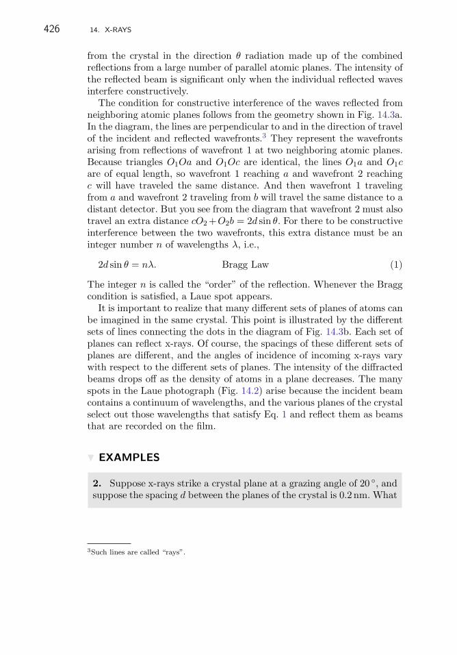
426 14. X-RAYS
from the crystal in the direction θ radiation made up of the combinedreflections from a large number of parallel atomic planes. The intensity ofthe reflected beam is significant only when the individual reflected wavesinterfere constructively.
The condition for constructive interference of the waves reflected fromneighboring atomic planes follows from the geometry shown in Fig. 14.3a.In the diagram, the lines are perpendicular to and in the direction of travelof the incident and reflected wavefronts.3 They represent the wavefrontsarising from reflections of wavefront 1 at two neighboring atomic planes.Because triangles O1Oa and O1Oc are identical, the lines O1a and O1care of equal length, so wavefront 1 reaching a and wavefront 2 reachingc will have traveled the same distance. And then wavefront 1 travelingfrom a and wavefront 2 traveling from b will travel the same distance to adistant detector. But you see from the diagram that wavefront 2 must alsotravel an extra distance cO2 +O2b = 2d sin θ. For there to be constructiveinterference between the two wavefronts, this extra distance must be aninteger number n of wavelengths λ, i.e.,
2d sin θ = nλ. Bragg Law (1)
The integer n is called the “order” of the reflection. Whenever the Braggcondition is satisfied, a Laue spot appears.
It is important to realize that many different sets of planes of atoms canbe imagined in the same crystal. This point is illustrated by the differentsets of lines connecting the dots in the diagram of Fig. 14.3b. Each set ofplanes can reflect x-rays. Of course, the spacings of these different sets ofplanes are different, and the angles of incidence of incoming x-rays varywith respect to the different sets of planes. The intensity of the diffractedbeams drops off as the density of atoms in a plane decreases. The manyspots in the Laue photograph (Fig. 14.2) arise because the incident beamcontains a continuum of wavelengths, and the various planes of the crystalselect out those wavelengths that satisfy Eq. 1 and reflect them as beamsthat are recorded on the film.
� EXAMPLES
2. Suppose x-rays strike a crystal plane at a grazing angle of 20 ◦, andsuppose the spacing d between the planes of the crystal is 0.2 nm. What
3Such lines are called “rays”.

14.5. THE BRAGG LAW OF CRYSTAL DIFFRACTION 427
wavelength will emerge at 20 ◦ to the crystal? The first-order value ofλ is just
λ = 2d sin θ = 2 × 0.2 sin 20 ◦ = 0.137 nm.
There might also be a second-order or a third-order wavelength present.
� EXERCISES
2. Suppose the crystal in the above example is rotated to 30 ◦ with re-spect to the incident beam and the detector is rotated to 30 ◦ withrespect to the crystal. What is the wavelength of the x-rays that aredetected?
Powder Diffraction Patterns
If you use x-rays of a single wavelength, you can also obtain diffractionpatterns from powdered samples. A powdered sample of crystalline ma-terial consists of many small crystals randomly oriented relative to eachother; foils of hammered metal may also consist of many small randomlyoriented crystals. When such a sample is irradiated with x-rays, the out-going diffracted x-rays form a pattern of concentric rings like that shownin Fig. 14.4a and not the array of spots observed in the Laue experiments.Such diffraction from many small randomly oriented crystallites is called“Debye–Scherrer diffraction.”
Each ring of the Debye–Scherrer diffraction pattern (Fig. 14.4) cor-responds to a different spacing between planes in the crystal beingirradiated. To see how a ring might arise, consider a single set of par-allel atomic planes within a tiny crystal. If the crystal is tipped so thatthe incoming beam is incident at the angle θ satisfying the Bragg law, abeam will be diffracted and emerge at an angle 2θ relative to the incidentbeam and at an angle θ relative to the plane of the crystal, as illustratedschematically in Fig. 14.4b. For the particular spacing d there will bea few other orientations of the crystal relative to the beam that satisfythe Bragg law. These orientations correspond to the higher orders, i.e.,n = 2, 3, etc.
If the crystal can be tipped only about an axis perpendicular to theplane of the page, as in Fig. 14.4b, the outgoing Bragg reflected beam will

428 14. X-RAYS
2
2
(c)
(b)(a)
FIGURE 14.4 Why small randomly oriented crystallites produce ring-shaped x-raydiffraction patterns: (a) example of Debye–Scherrer diffraction; (b) schematic illus-tration of a crystallite satisfying the Bragg law for the incident x-ray wavelength;(c) randomly oriented crystallites will produce a cone of radiation at an angle 2θ to theaxis of the incident beam; this forms the circular pattern on the photograph.
lie only in that plane. However, if the crystal were rotated about an axisparallel to the incident beam, the beam would go off at some angle outof the plane of the page. Therefore, from a sample consisting of a largenumber of tiny crystallites oriented every which way, the outgoing beamswill lie along the surface of a cone around the incident beam, as shownin Fig. 14.4c. When these cones meet a photographic plate some distanceaway, they produce circles like those shown in Fig. 14.4a.
� EXERCISES
3. Explain what pattern might appear on the photograph if the x-rayshad a continuum of wavelengths. Why would this not be useful?

14.6. A DEVICE FOR MEASURING X-RAYS: THE CRYSTAL SPECTROMETER 429
14.6 A DEVICE FOR MEASURING X-RAYS:THE CRYSTAL SPECTROMETER
The Braggs realized that diffraction from the planes of a single crystalspread x-rays out in space according to their wavelengths, and that thisproperty could be the basis for constructing a spectrometer for x-rays.To make their x-ray spectrometer they arranged a crystal at an angle θrelative to the beam coming from an x-ray tube and placed a detector atan angle θ relative to the crystal, as shown in Fig. 14.5. According to Eq. 1,only those x-rays with wavelength λ = 2d sin θ or, less likely, some simplefraction, e. g., λ/2, λ/3, will undergo Bragg reflection through the angle θ.Thus the device selects out from all the different wavelengths of incidentx-rays the particular wavelengths that will produce a beam at angle θ.As θ is changed (by rotating the crystal), the wavelength of the Braggreflected beam changes as determined by the Bragg equation. Then thedetector is rotated to the new value of θ to intercept the outgoing beamof the new wavelength. By successive rotations of crystal and detector,through θ and 2θ respectively, you can measure the intensity of x-rays asa function of λ.
Determining the Spacing of Atoms in Crystals
Notice that to extract useful numbers you need to know either the spacingd between planes of atoms in the crystal or the wavelength λ. If you knowthe crystal spacing, you can use the crystal spectrometer to measure x-raywavelengths. If you know the wavelength, then you can use those x-raysto measure the spacings of various crystals and so learn how crystalline
2
Detec
tor
S1 S2
S3Collimating slits
Crystal on turn-table
FIGURE 14.5 Schematic diagram of a Bragg spectrometer.

430 14. X-RAYS
solids are put together. Physicists do both: They use crystals to studyx-rays; they use x-rays to study crystals. But how do they get started?It is necessary to measure some crystal spacing or some x-ray wavelength.After that you can use one to measure others. Where do you get the firstmeasurement?
From its Laue pattern the Braggs were able to infer that the Na andCl atoms of a crystal of table salt sit on the corners of a cube equallyspaced a distance d from one another. For such a simple structure thevolume occupied by a single atom is d3, and a numerical value of d3
can be calculated from the molar weight MM, the density ρ of salt, andAvogadro’s number NA.
A mole of NaCl has a mass of M = 35.453 + 22.99 = 58.443 g, and thedensity of salt is ρ = 2.163 g cm−3. Therefore, the volume of a mole ofNaCl is
58.4432.163
= 27.01 cm3.
Because 1 mole of NaCl contains 2 moles, i.e., 2NA, of atoms, each atomoccupies a volume
d3 =27.01
2 × 6.022 × 1023cm3,
from which it follows that
d = 2.820 × 10⁻⁸ cm = 0.2820 nm.
It is common, especially in older books, to measure atomic-sized lengthsin angstroms (A) where 1 A = 10−8 cm = 10−10 m = 0.1 nm. In theseunits the spacing between the planes of a rock salt crystal is d = 2.82 A.In modern textbooks, however, it is customary to use nanometers foratomic-sized dimensions, and we will do that.
Knowing the spacing of a rock-salt crystal, you can make quantitativemeasurements of the yield of x-rays as a function of wavelength, and youcan find spacings of other crystals.
� EXAMPLES
3. For example, one might take x-rays from a tungsten target, formthem into a beam with slits, as in Fig. 14.5, and allow them to strikea crystal of rock salt. The x-rays emitted at an angle of, let’s say, 25 ◦will then have a wavelength of λ = 2d sin θ = 2 × 0.2820 × sin 25 ◦ =0.2384 nm.
In this way the Bragg spectrometer is used to measure unknown x-raywavelengths.

14.7. A DEVICE FOR MEASURING X-RAYS: THE CRYSTAL SPECTROMETER 431
� EXAMPLES
4. The x-rays coming from the rock-salt crystal in Example 3 areallowed to strike a calcite crystal (CaCO3). The calcite crystal is rotateduntil there is a strong reflection from it. This occurs when the angles ofgrazing incidence and reflection are each 23.1 ◦. From this measurementyou can deduce that the spacing of the planes of atoms in the calcitecrystal is
d =0.2384
2 sin 23.1 ◦ = 0.3036 nm.
In this way a known x-ray wavelength is used to find an unknownspacing of atoms, i.e., the x-rays are used to explore the structure ofcrystalline matter.
� EXERCISES
4. At what angle would such a beam of x-rays reflect strongly from aquartz crystal? From a mica crystal?
It is important to keep in mind that there are many other sets of planeswithin the crystals, and each set will give rise to an x-ray beam when theBragg law is satisfied. The theory of these is elaborate, but the abovesimple examples suffice to show you how x-rays can be used to find newdetails of atomic structure.
The spacing of the calcite crystal is useful information because calcitewas a crystal frequently used in early x-ray spectrometers. Its spacing andthose of some other historically important crystals are given in Table 14.1.
TABLE 14.1 Spacing betweenplanes of commonly used crystalsat 18 ◦C
Crystal d (nm)
Calcite CaCO3 0.3036
Rock salt NaCl 0.2820
Quartz SiO2 0.4255
Mica SiO2 0.9963

432 14. X-RAYS
14.7 CONTINUUM X-RAYS
Using known crystal spacings you can make a spectrometer from anyconvenient crystal and measure how much of each different wavelengthis present in the x-rays. Ulrey used a Bragg spectrometer with a calcitecrystal to measure the intensity of x-rays from a tungsten target as afunction of the angle of orientation θ of the crystal. This angle is relatedto the wavelength by the Bragg law, Eq. 1.
Remember that in a Bragg spectrometer (Fig. 14.5) the detector isrotated to view an exit angle θ corresponding to the angle of grazingincidence θ. In other words, the detector must always be at an angle of2θ relative to the axis of the incident beam of x-rays in order to registerthe intensity of the x-rays diffracted through the Bragg angle θ. WithVacc = 50 kV and setting the crystal and detector at many different angles,Ulrey obtained the data shown in Table 14.2: the intensity distribution ofthe x-rays produced when energetic electrons strike a tungsten (W) anodein an x-ray tube.
Ulrey’s data4 are plotted in Fig. 14.6 for several values of Vacc. Theyshow two particularly interesting features: a continuous, smooth variation
TABLE 14.2 Intensity of X-rays vs. angle of grazing exit θfrom calcitea
X-Ray intensity θ X-Ray intensity θ
(relative units) (degrees) (relative units) (degrees)
1.9 2.45 6.4 6.24
5.0 2.83 5.6 6.62
6.8 3.30 4.8 6.91
8.6 3.59 4.1 7.19
9.5 3.87 3.2 7.57
9.9 4.25 2.6 7.86
9.9 4.53 2.3 8.14
9.6 4.91 2.0 8.52
9.1 5.29 1.7 8.81
8.0 5.58 1.5 9.19
7.0 5.86a Taken from Ulrey, Phys. Rev. 11, 401 (1918).
4C.T. Ulrey, “Energy in the continuous x-ray spectra of certain elements,” Phys. Rev. 11,401–410 (1918).

14.8. X-RAY PHOTONS 433
00
2
4
6
8
10
0.02 0.04 0.06 0.08 0.10
Wavelength (nm)
Rel
ative
inte
nsi
ty
50 kV
40 kV
30 kV
20 kV
FIGURE 14.6 Relative intensity of continuum x-rays from electrons striking a tung-sten target. Each curve is labeled with the voltage through which its correspondingelectrons were accelerated. Taken with permission from C.T. Ulrey, Phys. Rev. 11,401–410 (1918) c©1918 The American Physical Society.
of intensity from long wavelengths down to some short wavelength and asudden termination, or “cutoff,” of the curve at that short wavelength.
The continuum is to be expected from the simple picture of howx-rays are produced. Not all electrons striking the target undergo thesame acceleration; some are accelerated suddenly, some less so. Thedistribution of wavelengths should follow the distribution of accelera-tions. The largest intensity corresponds to the acceleration that occurswith greatest probability.
But the short wavelength cutoff warns us that this simple picture isincomplete. Although we might expect extremely sudden decelerations tobe less probable, there is no reason in classical physics why their probabil-ity should suddenly drop to zero. Classical physics leads us to expect thatthe continuum will peter out at short wavelengths, not stop suddenly.
14.8 X-RAY PHOTONS
The short-wavelength cutoff is explained by the granular nature of electro-magnetic radiation. Just as there are photons of visible light, so also arethere x-ray photons, and x-ray energy comes in packets E = hf = hc/λ.

434 14. X-RAYS
Because x-ray photons cannot have energy larger than the maximumkinetic energy of the incident electrons, electrons of charge e acceler-ated through a voltage V cannot produce photons with energies greaterthan eV . Therefore, there will be a shortest possible λ, and it will be
λcutoff =hc
eV. (2)
In Fig. 14.6 the curves are labeled with the accelerating voltage appliedto the x-ray tube. As expected, the value of the cutoff wavelength becomessmaller as the accelerating voltage is increased.
� EXAMPLES
5. What should be the cutoff wavelength for an accelerating voltageof 30 kV?
Electrons accelerated through 30 kV cannot deliver more than 30 keVof energy to the target. Therefore, the shortest possible x-ray wave-length is hc/(eV ) = 1240/30 000 = 0.0413 nm. This agrees well withUlrey’s data.
Table 14.3 shows cutoff wavelengths determined from Ulrey’s data forvarious accelerating voltages.
� EXERCISES
5. Use Eq. 2 to predict the cutoff wavelengths for the curves labeled40 kV and 20 kV in Fig. 14.6. How do your answers compare withUlrey’s data?
TABLE 14.3 X-Ray tube voltage andcutoff wavelengths
Tube voltage (kV) λcutoff (nm)
20 0.062
30 0.0413
40 0.031
50 0.0248

14.9 THE COMPTON EFFECT 435
6. In an old fashioned color-television tube electrons pass througha potential difference of 30 kV before they strike the phosphorescentscreen at the end of the tube. What is the maximum energy that anx-ray photon can have coming from this tube? What is the wavelengthof that photon?
7. In the previous exercise what (approximately) is the most probableenergy of photon that will be produced by the TV tube?
14.9 THE COMPTON EFFECT
Introduction
The existence of the short wavelength cutoff is a reminder that x-raysdo not always behave like waves. Indeed, studies with the crystal spec-trometer and other techniques for measuring x-rays show that in somecircumstances they behave like hard, featureless particles. Photons cancollide with electrons and bounce off them like tiny BBs.
Bragg scattering is an important special case of the interaction of x-rayswith matter, but it is not the only kind of x-ray scattering. A beam ofx-rays directed at a crystal will result in the weak emission of x-rays atall angles relative to the incident beam. In the early 1920s, the Americanphysicist Arthur Holly Compton studied this kind of x-ray scattering. Hescattered x-rays of a single well-defined wavelength from a small pieceof carbon and observed that at scattering angles other than 0 ◦ someof the scattered radiation came out with its wavelength unchanged andsome came out with its wavelength increased. He explained the change inwavelength as the result of a billiard-ball-like collision of an x-ray photonwith a nearly free electron of a carbon atom. Such a change in wavelength(or energy) of a photon after it scatters from a charged particle is calledthe “Compton effect.”
The discovery and explanation of the Compton effect decisively per-suaded physicists of the granularity of light. This was important becausethe idea of corpuscular electromagnetic radiation, e.g., photons of lightor of x-rays, was widely doubted even after Einstein explained thephotoelectric effect in terms of the absorption of photons.

436 14. X-RAYS
Compton Scattering
Figure 14.7 shows a diagram of the apparatus Compton used to exhibit theeffect. X-rays of a well-defined wavelength5 were generated by a speciallydesigned x-ray tube and directed at a small block of graphite (carbon)place near the anode at the point R in the figure. The x-ray source andthe graphite were surrounded by a lead box. The graphite scattered thex-rays in all directions, but collimating slits S1 and S2 allowed only x-rays scattered through a chosen angle θ to escape from the box. For thesetup shown in Fig. 14.7 the scattering angle is θ = 90 ◦. These scatteredx-rays are quite weak, so the graphite must be placed close to the anodeto increase their intensity.
To measure the wavelengths of the scattered x-rays, Compton let themstrike a calcite crystal that he used as an x-ray spectrometer. By rotatingthe calcite and the detector, as shown in Fig. 14.5, and using the BraggLaw, he could measure the intensity of the scattered x-rays as a functionof their wavelength.
Figure 14.8 shows Compton’s results for scattering angles θ = 45 ◦,90 ◦, and 135 ◦. The y-axis in each figure is the intensity measured by thedetector. The x-axis displays the Bragg angle θB of reflection from thecalcite crystal in the spectrometer. To find the wavelength of each peak,
FIGURE 14.7 Diagram of Compton’s apparatus. Taken with permission fromA.H. Compton, Phys. Rev. 22, 409–413 (1923) c©1923 The American Physical Society.
5In addition to the spectrum of continuum radiation (Sect. 14.7), x-ray tubes also emit intenseradiation at one or more well-defined wavelengths. These “characteristic” wavelengths becomemuch more intense than the continuum radiation as the accelerating voltage is increased; youwill encounter them again in Chap. 17.

14.9. THE COMPTON EFFECT 437
A
B
C
6 30 7 7 30
Scattered bygraphite at
45
90Scattered at
135
FIGURE 14.8 Compton’s data showing the appearance of the longer-wavelengthx-rays as the scattering angle θ is increased; the abscissa is the angle θB of the Braggspectrometer. Taken with permission from A.H. Compton, Phys. Rev. 22, 409–413(1923) c©1923 The American Physical Society.
you apply Bragg’s Law to θB. (Note that there are two different anglesin this discussion: θ is the angle through which x-rays are scattered fromthe graphite, and θB is the angle of reflection from the calcite crystal ofthe spectrometer.)
� EXAMPLES
6. For calcite d = 0.3036 nm. From the scale of Fig. 14.8 you can seethat the primary peak occurs at 6 ◦ 42′ = 6.7 ◦. The wavelength of thex-rays making this peak must then be
λ = 2 × 0.3036 sin 6.7 ◦ = 0.0708 nm.
The figure shows that a second peak emerges and moves toward largerBragg angles as the scattering angle is increased. Larger Bragg anglescorrespond to longer wavelengths and thus to lower photon energies.

438 14. X-RAYS
TABLE 14.4 Relative intensity of X-rays scatteredfrom carbon
θ = 135 ◦ Wavelength θ = 135 ◦ Wavelength
Intensity (nm) Intensity (nm)
4.3 0.0688 13.8 0.0734
0.5 0.0689 20.0 0.0739
5.5 0.0697 25.8 0.0745
8.0 0.0703 25.6 0.0750
13.0 0.0707 18.9 0.0754
7.8 0.0713 10.8 0.0760
3.0 0.0719 4.8 0.0765
2.8 0.0725 2.0 0.0773
11.0 0.0729
� EXERCISES
8. Use the data in Fig. 14.8 to find the wavelength of the lower energyphotons when the scattering angle is 90 ◦.
Table 14.4 shows the data Compton obtained when he scattered0.0708 nm radiation, looked at x-rays coming out at 135 ◦, and used theBragg Law to find their wavelengths.
� EXERCISES
9. Make a graph of the data in Table 14.4 and draw a smooth curvethough the points. Label the peak that has the same wavelength as theincident photons; label the peak that arises from Compton scattering.By how much is the wavelength shifted?
The occurrence of the shifted peak is the Compton effect. Comptonexplained the effect as due to elastic scattering, i.e., scattering like that ofhard spheres bouncing off each other. One of the “spheres” was an electronin the carbon; the other was a packet of electromagnetic energy—thephoton. Elastic scattering of a photon from an unbound charged particleis called “Compton scattering.”

14.9. THE COMPTON EFFECT 439
The fact that Compton’s explanation worked so well led to generalacceptance of the concept of the particle-like photon with energy hf ,where h is Planck’s constant and f is the frequency of the radiation.
Derivation of the Energy Change of a Compton Scattered Photon
Figure 14.9a is a diagram of the scattering process as Compton imaginedit. A photon of energy hf enters from the left and strikes a stationaryelectron of rest mass m. After the collision, the electron recoils awaywith momentum pe at an angle φ with respect to the line of motion ofthe incident photon, and a photon of energy hf ′ travels away at an angleof θ; the electron stops inside the target and is not measured. Becausethe electron has gained energy from the collision, the outgoing photon’senergy of hf ′ will be less than that of the incoming photon hf .
Although the data in Table 14.4 are the wavelengths λ and λ′, it is moreconvenient to discuss Compton scattering in terms of the correspondingfrequencies f and f ′ and derive a relationship between f ′ and f and thescattering angle θ.
To do this use the relativistically correct expressions for conservationof energy and momentum. First notice that the relation of photon energyto photon momentum is
E = hf =√
0 + p2c2
because m0 = 0 for a photon. Therefore, for a photon,
E = hf = pc.
� EXERCISES
10. Show from the above equation that for a photon, p = h/λ.
p
pe
p
Before After
(a) (b)
FIGURE 14.9 (a) Schematic representation of a Compton scattering event. (b)Momentum diagram of Compton scattering.

440 14. X-RAYS
Now use this relationship between photon energy and photon momen-tum to write down the total energy of the photon and electron before thecollision and after. Before the collision, the energy is just the photon’senergy plus the rest energy of the electron: pc + mec
2. After the collision,the total energy is the photon’s somewhat lower energy p′c plus the elec-tron’s larger energy, as shown below. Because energy is conserved, thetotal energy before the collision equals the total energy after:
pc + mec2 = p′c +
√m2
ec4 + p2
ec2, (3)
where pe is the momentum of the recoiling electron and me is its restmass.
To find the relation of the scattering angle of the photon and itsmomentum after scattering, use conservation of momentum as well asconservation of energy. Conservation of momentum gives two more equa-tions that you can use to eliminate pe from Eq. 3 so that you can find thephoton’s momentum and thus its energy.
In Fig. 14.9a a photon travels toward positive x and scatters from anelectron as shown. The electron recoils at an angle φ while the photon goesoff at an angle θ relative to the x-axis. Figure 14.9b shows that there aretwo momentum equations, one for vertical, or y, momentum, and the otherfor horizontal, or x, momentum. In the y direction the total momentumis initially zero, so after the collision the amount of momentum up mustequal the amount down, and
p′ sin θ = pe sinφ. (4)
The amount of momentum in the x direction before the collision equalsthe total amount in the x direction after, so
p = p′ cos θ + pe cos φ. (5)
Our aim is to find p′ of the outgoing photon in terms of the incident pand the scattering angle θ. This means that we need to eliminate both φand pe from Eqs. 3, 4, and 5.
Whenever you have an angle α appearing in trigonometric functionsthat you want to eliminate from a set of equations, the first approach isto see whether you can combine the trig functions in such a way that youcan use the identity sin2 α + cos2 α = 1.
Rewrite Eq. 5 as
p − p′ cos θ = pe cos φ (6)
and square it to get
p2 + p′2 cos2 θ − 2pp′ cos θ = p2e cos2 φ.

14.9. THE COMPTON EFFECT 441
Square Eq. 4 to get
p′2 sin2 θ = p2e sin2 φ.
Add the two equations and use the trig identity to eliminate φ:
p2e = p2 + p′2 − 2pp′ cos θ. (7)
� EXERCISES
11. Show that Eq. 7 is correct by deriving it as above but include anymissing steps.
Replace p2e in Eq. 3 with the expression given by Eq. 7, to eliminate the
electron momentum. The result is an explicit expression for p′ in termsof the incident p and the outgoing scattering angle θ:
(pc − p′c + mec2)2 = m2
ec4 + p2
ec2,
(pc − p′c + mec2)2 − m2
ec4 = p2
ec2 = p2c2 + p′2c2 − 2pp′c2 cos θ,
pp′(1 − cos θ) = mec(p − p′), (8)
p′ =mepc
p(1 − cos θ) + mec. (9)
� EXERCISES
12. Do this entire derivation from start to finish.
13. From Eq. 9 show that f ′ in terms of f and θ is
hf ′ =hf
hfmec2
(1 − cos θ) + 1, (10)
which is very convenient for calculating how the energy of a photonchanges when it scatters.
It is often helpful to express these photon energies relative to the restenergy of the electron. Notice that if you define the ratio of the photonenergy to the electron rest energy as
x =hf
mec2,

442 14. X-RAYS
you can write Eq. 10 in the compact form
x′ =x
x(1 − cos θ) + 1. (11)
� EXAMPLES
7. Remembering that the rest mass energy of an electron is 511 keV,suppose a 256 keV photon undergoes Compton scattering through 180 ◦.What will be the energy of the outgoing photon? What will be theenergy of the recoiling electron?
For this case x = 12 . Since cos θ = −1, it follows from Eq. 11 that
x′ = 14 . This means that hf ′ = 511/4 = 128 keV. Because the electron
must have the remaining part of the energy, its kinetic energy in thisparticular case will be 128 keV.
Another virtue of this version (Eq. 11) of the Compton scattering equa-tion is apparent if you want to know about Compton scattering fromparticles other than an electron. Suppose you want to know what happensto a photon that scatters off a proton, mpc
2 = 938MeV.
� EXAMPLES
8. To see what happens when a 256 keV photon scatters 180 ◦ from aproton, calculate x = 0.256/938 = 2.729 × 10⁻⁴, from which it followsthat x′ = 2.728 × 10⁻⁴. There is hardly any effect.
� EXERCISES
14. If a 100 keV photon scatters from an electron through an angle of90 ◦, what will be the recoil energy of the electron?
15. What is the maximum energy that an electron can acquire froma 600 keV photon by means of Compton scattering?
The Compton effect is customarily described as a change in wavelengthrather than as a change in frequency. To get it in that form divide both

14.9. THE COMPTON EFFECT 443
sides of Eq. 8 by pp′ and also by me. This gives
1 − cos θ
me= c
(1p′
− 1p
)
= c
(λ′
h− λ
h
)
,
where p and p′ have been replaced by h/λ and h/λ′ respectively, and itfollows that
λ′ − λ =h
mec(1 − cos θ). (12)
When physicists refer to the “Compton scattering equation” or to theequation for “Compton wavelength shift,” they mean Eq. 12, which givesthe change in wavelength of the scattered photon as a function of its angleof scattering.
Equation 12 shows the curious fact that the change in wavelength dueto Compton scattering does not depend upon the frequency (i.e., energy)of the incident photon.
� EXERCISES
16. Is the frequency shift of the scattered photon independent of thefrequency of the incident photon? Explain.
17. Table 14.4 shows actual Compton scattering data. What is theenergy of the 0.07078 nm incident photon? Calculate the shift in wave-length you would expect when that photon scatters through 135 ◦. Howwell does your answer compare with the data shown in Table 14.4?
Compton Scattering and the Detection of Photons
Radioactive materials often emit energetic photons called, for historicalreasons, “gamma rays.” Radioactive cesium emits a gamma ray with anenergy of 662 keV. Obviously, this is not a visible photon.
� EXERCISES
18. How do you know that this photon is not visible?
As previously noted, such photons, although not visible themselves,can cause other materials to emit visible light. We described in Chap. 13how a photon can deposit energy in a crystal of sodium iodide [NaI(Tl)]

444 14. X-RAYS
and cause the crystal to give off a flash of light that can be detectedwith a photomultiplier tube. By measuring the relative intensity of thescintillations you can measure the relative amounts of energy left by thephotons in the crystal.
A common measurement of photons is to count the number of flashesthat appear in the crystal and sort the counts according to how brightthe flashes are.
The graph in Fig. 14.10 was obtained after hundreds of thousands ofphotons passed through a NaI(Tl) crystal. Of these, somewhere between1% and 10% produced flashes of light. The flashes were counted and sortedaccording to their brightness. The graph shows the number of flasheson the y-axis and the brightness along the x-axis. Because brightness isproportional to energy deposited in the crystal, it is convenient to labelthe brightness scale with the corresponding photon energy, and that isdone here.
If flashes came only from complete absorption of incoming single-energyphotons, there would be only one size of flash. In Fig. 14.10 you can seethat many of the flashes correspond to photons of 662 keV. This group ofphotons is labeled “photopeak” on the graph. The energies of the emittedphotons are very closely the same, but because the flashes of light thatthey produce vary somewhat in brightness, the peak in the graph is wide.We say that the “resolution” of the instrument is not perfect. The name“photopeak” always refers to the peak corresponding to the full energy ofthe incident photon.
0
0
100
100 200 300 400 500 600 700 800
200
300
Backscatter peak
Compton edge
Photopeak
Photon energy (keV)
Num
ber
of photo
ns
FIGURE 14.10 Distribution of energy deposited in a NaI(Tl) crystal by 662 keVphotons emitted following the radioactive decay of 137Cs.

14.9. THE COMPTON EFFECT 445
Figure 14.10 shows that other things are going on besides absorptionof 662 keV photons. The experimenter detected flashes of light over quitea range of brightnesses corresponding to the absorption of energy from0keV up to 800 keV. Two features show up particularly: the bump labeled“backscatter” and the sudden drop from a constant level of counts labeled“Compton edge.”
It turns out that there are several ways for a photon to deposit energyin a crystal, and these depend on the energy of the photon. For example,between 250 keV and 1.02 MeV a photon is most likely to do either of twothings. It may produce a photoelectron in the crystal and leave all of itsenergy in the crystal. Or it may Compton scatter off a nearly free electronof some atom and leave the crystal; the energy left in the crystal is thenwhatever was given to the electron by the Compton scattering. This willproduce a smaller flash of light than total absorption because the energyleft in the crystal is smaller. It is in this way that most of the lower-energylight pulses occur.
You can use your knowledge of Compton scattering to calculate theenergies at which the backscatter peak and the Compton edge occur.The Compton edge corresponds to an event in which a photon enters thecrystal and undergoes 180 ◦ Compton scattering from an electron of one ofthe crystal’s atoms and then leaves the crystal with reduced energy. Theelectron remains behind with increased energy, which goes to produce aflash in the crystal. The electron can not acquire more energy than theamount imparted when the photon scatters through 180 ◦, so there is anoticeable decline in the number of light pulses beyond this energy. Thisdecline is called the “Compton edge.”
� EXERCISES
19. Under what circumstances will a photon that is Compton scat-tered out of the crystal leave the most possible energy with the electronfrom which it scattered?
20. Calculate the maximum energy that a 662 keV photon will impartto an electron. How does your answer correspond to the energy on theaxis of the graph in the region labeled “Compton edge”?
21. To what do you attribute the counts observed at energies belowthe Compton edge?
The backscatter occurs because the NaI crystal is surrounded by densematerial, and there is a fair probability that some photons will enter the

446 14. X-RAYS
crystal, pass through it unabsorbed, and then scatter off electrons of sur-rounding metal (usually aluminum, but it does not make much difference).These photons scatter back into the crystal (hence the name, backscat-ter) where they are absorbed. The crystal is usually arranged so that onlythose photons that bounce directly back are likely to reenter the crystal.Of course, photons that have scattered through 180 ◦ are reduced in en-ergy, and the flashes of light that they can produce will not be as brightas those produced by the full-energy photons.
� EXERCISES
22. What is the energy of a 662 keV photon after it Compton scatters180 ◦ off Al? Off Si? Off Fe?
23. Compare your answer to the previous question with the energycorresponding to the “backscatter peak” in the graph. Why should theybe the same?
14.10 SUMMARY
Useful Things to Know
X-rays are usually produced by sudden acceleration of charged particles.In practical circumstances x-rays are made when energetic electrons arebrought to a sudden halt by collision with a metal electrode.
The existence of Laue diffraction spots and Debye–Scherrer diffractionrings shows that x-rays are waves with wavelengths a thousand timessmaller than those of visible light.
Diffraction of x-rays by crystals obeys the Bragg law
2d sin θ = nλ, Bragg Law
where d is the spacing between successive planes of atoms in the crystal,θ is the angle of grazing incidence, λ is the wavelength of the x-rays, andn is an integer n = 1, 2, . . . . In any given crystal there will many sets ofplanes with different spacings. The Bragg law holds for each set.
The Bragg law is the basis for the design and operation of the crystalspectrometer. With this device it is possible to measure x-ray wavelengthsand map out the intensity of x-ray emissions as a function of wavelength.
X-rays also exhibit particle-like behavior. To understand the short-wavelength cutoff of the continuous x-ray spectrum, it is necessary to

14.10 SUMMARY 447
assume that x-rays are photons each with energy E = hf . Further-more, the Compton effect, i.e., the decrease in energy of x-rays as theangle at which they are scattered from free or weakly bound electronsincreases, can be understood as resulting from the scattering of one smallstructureless object by another.
Some Important Things to Keep in Mind
If the wavelengths of x-rays are thousands of times smaller than thoseof visible light, they can in principle be used to probe the structure ofobjects thousands of times smaller than the smallest things we can seewith our eyes. But notice that x-ray photons are going to be thousandsof times more energetic than visible ones; the energy scale shifts from eVto keV.
X-rays are a valuable probe that can yield interesting information aboutstructures as small as 0.1 nm, that is, as small as atoms. By making x-raysof energies of 100 keV and higher, it is possible to probe even smallerstructures.
Studies of atoms with x-rays supported two major advances of under-standing about atoms. The works of von Laue and the Braggs showedthat crystals are made of regular arrays of atoms. The Compton effectprovided quite direct evidence that the electrons are constituent parts ofevery atom.
Be able to convert from energy to wavelength and vice versa withouthesitation.
� EXAMPLES
9. For example, what is the wavelength of a 100 keV photon? BecauseE = hf = hc/λ, a 100 keV photon has a wavelength λ = hc/E. Neverforget that hc = 1240 eVnm. Then if you know E in units of eV, youcan immediately get that λ = 1240
100×103 = 0.0124 nm.
� EXERCISES
24. What is the wavelength of a 12.4 keV photon?

448 14. X-RAYS
FIGURE 14.11 Representation of a crystal lattice (Problem 1).
d110 d210
a
FIGURE 14.12 Schematic representation of a cubic crystal with interatomic spacinga (Problem 2).
PROBLEMS
1. The Bragg Law for crystal diffraction of x-rays is 2d sin θ = λ. UseFig. 14.11 to show:
a. What the symbols d and θ refer to.b. What is meant by Bragg diffraction.
2. Figure 14.12 shows a cubic crystal with interatomic spacing a. Usetrigonometry to find the interplanar spacings in terms of a for the atomicplanes indicated by d110 and d210.

PROBLEMS 449
3. Using the data in Table 14.2 on p. 432 and the fact that Ulrey’sspectrometer used a calcite crystal:
a. Calculate the wavelengths corresponding to angles of reflection,and then plot the intensity of the x-radiation vs. λ.
b. What is the energy of the photon that corresponds to thewavelength at which the intensity is a maximum?
c. By extrapolation of your graph determine the short-wavelengthcutoff.
d. What is the voltage difference through which these electrons passedbefore they struck the tungsten anode of the x-ray tube?
4. Electrons in an x-ray tube are accelerated through a potentialdifference of 50 kV.
a. What is their kinetic energy?b. What is the speed of these electrons in terms of c?c. Are relativistic effects important in
i. determining the kinetic energy?ii. determining the speed?
5. Ulrey observed that continuous x-ray spectra generated with elec-trons produced with the x-ray tube voltages shown in Table 14.3 (p. 434)exhibited sharp cutoffs at the wavelengths shown in the table.
a. Predict what sort of a curve you will get if you plot f (or hf) vs.V . Explain your prediction.
b. Using the insights you generated to make your prediction in thepreceding, derive a formula relating the voltage V of an x-ray tubeto the maximum frequency fmax of the emitted radiation.
c. Why is this formula familiar to you?
6. Some teachers like to use general questions in exams such as:a. What is the Compton effect?b. How is the Compton effect important to our understanding of the
nature of electromagnetic radiation?
7. A photon Compton-scatters from an electron through an angle of 90 ◦,as shown in Fig. 14.13. In doing so, it loses half its initial energy:
a. What is the photon’s initial wavelength?b. What are the initial and final energies of the photon?

450 14. X-RAYS
= —E
90
, E
, E 12
e
FIGURE 14.13 Compton scattering event (Problem 7).
Crystal
Carbon
Vacc
FIGURE 14.14 Compton scattering arrangement for Problem 8.
c. Suppose the photon scattered through 180 ◦ instead of 90 ◦. Whatwould be its final wavelength and energy (λ′, E′)?
d. When the photon scatters through 180 ◦, what is the final energyof the electron?
8. Monochromatic x-rays of wavelength λ = 0.243 nm are produced inthe following way: Electrons bombard a metal target in a standard x-raytube, and the resulting radiation is reflected from a crystalline material,as shown in Fig. 14.14.
a. What is the purpose of the crystal?b. What is the minimum accelerating voltage Vacc that could have
produced x-rays of this λ?c. The reflected x-rays go on to collide with a carbon block C, where
their wavelength is shifted to λ′ by the Compton effect. For thedirection shown in the drawing, calculate the change in wavelength.
d. Does the x-ray gain or lose energy in this process? Where doesthe energy go? What is the most striking assumption made byCompton in his analysis of this phenomenon?

PROBLEMS 451
B: Carbon
A: Source
C: Crystal(CaCO3)
FIGURE 14.15 A Compton scattering arrangement in which the incident x-rays havea single well-defined wavelength (Problem 9).
90
Vacc
FIGURE 14.16 Compton scattering arrangement for Problem 10.
9. Write a short description of the experiment depicted in Fig. 14.15.Include the following:
a. Identify and explain the purpose of items A, B, and C in Fig. 14.15.b. Discuss the significance of the experiment. Why were the exper-
imental results, and the analysis of those results, important andsurprising?
10. X-rays from an x-ray tube are Bragg reflected as shown in Fig. 14.16from the planes of a calcite crystal spaced 0.3036 nm apart. Photons ofwavelength λ = 0.3654 nm emerge from the crystal at an angle α with re-spect to their initial direction (see Fig. 14.16) and are Compton scatteredthrough an angle of 90 ◦ as they pass through a second material.
a. Find the angle α that the diffracted photon forms with its initialdirection.
b. What is the minimum accelerating voltage Vacc that would producea photon of the given wavelength?

452 14. X-RAYS
c. How much energy was lost by the photon, and where did theenergy go?
11. Figure 14.8 (p. 437) shows three of Compton’s scans obtained usingcalcite as the crystal in the analyzing Bragg spectrometer.
a. Use the information on the x-axis to calculate the wavelengths ofthe two peaks of the scattered radiation for each plot.
b. From the incident wavelength and the scattered angle use Comp-ton’s equation to calculate the wavelength of the radiation thatscattered from electrons for each plot.
c. Compare the results of (a) and (b).d. For each case calculate the energy gained by the scattered electron.
12. Explain why the sum of the backscatter energy Eback and the energyof the Compton edge Eedge should equal the energy of the photopeakEphoto, i.e.,
Eback + Eedge = Ephoto.
Find the values of these three quantities in Fig. 14.10 on p. 444 and showwhether or not they obey the expected relationship.
13.a. An electron tube (Fig. 14.17a) generates x-rays of intensity I1(λ),as shown in Fig. 14.17b. What is the voltage applied to the electrontube?
b. The x-rays from the tube are incident on a crystal. It is observedthat the x-rays that undergo Bragg diffraction emerge at the angleshown in Fig. 14.18a. The intensity of the emerging beam I2(λ) isshown in Fig. 14.18b. What is the spacing d between the planes ofthe crystal from which the x-rays have diffracted?
0.02 0.06 (nm)
I1
I1
(a) (b)
V
FIGURE 14.17 Intensity distribution of x-rays vs. λ for Problem 13(a).

PROBLEMS 453
0.02 0.06 (nm)
I2
I2
I1
(a) (b)
d 50
Crystal
210
FIGURE 14.18 Schematic of Bragg crystal and diffracted x-ray intensity forProblem 13(b).
0.02 0.06 (nm)
I3
I2
I3
(a) (b)
130
Carbon
= ?
FIGURE 14.19 Compton scattering and Compton effect for Problem 13(c).
c. The x-rays of part (b) are incident on a block of graphite, asshown in Fig. 14.19a. Photons Compton scattered through 130 ◦are observed to have a distribution of intensity I3 vs. wavelength, asshown in Fig. 14.19b. Calculate the wavelength λ′ of the scatteredx-rays.
d. How much energy is gained by electrons that Compton scatterphotons 130 ◦ as in part (c)?
14. X-rays generated in an x-ray tube are Bragg-reflected through 90 ◦ bya crystal (xtal in Fig. 14.20). The Bragg-reflected x-rays have a wavelengthλ = 0.4000 nm.
a. What is the spacing between the crystal planes causing thisreflection?

454 14. X-RAYS
acc
= 0.400 nm
xtal
90
90°
= 0.400 nm
xtal
90
90°acc
FIGURE 14.20 An x-ray photon Bragg scatters from a crystal (xtal) and thenCompton scatters from carbon (Problem 14).
1.0° 2.0° 3.0°
Intensity
FIGURE 14.21 Spectrum of x-rays Bragg scattered from crystal planes separated by0.94 nm (Problem 15).
b. What is the wavelength λ′ of the 0.4000 nm x-rays after they Comp-ton scatter through 90 ◦from an amorphous carbon block as shownin Fig. 14.20? Keep 4 significant figures in your answer.
c. How much energy did each x-ray photon lose when Compton-scattered through 90 ◦?
d. It takes 11.2 eV to eject an electron from a carbon atom (i.e., toionize the atom). What is the kinetic energy of the ejected electronafter it has left the atom?
15. An x-ray beam containing radiation of two distinct wavelengths scat-ters from a crystal, yielding the intensity pattern shown in Fig. 14.21. Thespacing between the planes of the scattering crystal is 0.94 nm. Find thetwo wavelengths.

1515C H A P T E R
Particlesas Waves
15.1 INTRODUCTION
You have seen that waves can act like particles. The energy of light wavesis packaged in quanta called photons. Photons can scatter from electronslike tiny hard objects. If this behavior is not surprising or mysteriousenough, it turns out that particles can act like waves. Electrons, protons,neutrons, and atoms all can exhibit interference and other forms of wavebehavior.
15.2 THE DE BROGLIE WAVELENGTH
The first clue that particles might have wavelike behavior came whenLouis de Broglie noted (as you saw in Chap. 14) that the momentum ofa photon is
p =hf
c=
h
λ(1)
and suggested that perhaps particles might obey the same equation. Inother words, he proposed that particles might behave as waves with awavelength of
λ =h
p. (2)
This wavelength of particles is called the “de Broglie wavelength.”What would be the size of such a wavelength? Some examples will show
you how the wavelength of a particle depends on its kinetic energy K.
C.H. Holbrow et al., Modern Introductory Physics, Second Edition, 455DOI 10.1007/978-0-387-79080-0 15, c© Springer Science+Business Media, LLC 1999, 2010

456 15. PARTICLES AS WAVES
� EXAMPLES
1. What is the de Broglie wavelength of a 10 keV electron? To answerthis question, first find the momentum of the 10 keV electron. Becausethis energy is less than 10% of the electron’s rest energy, you canuse the nonrelativistic expression connecting momentum p and kineticenergy K:
p2
2me= K.
To do your calculation in eV units, multiply and divide the left sideby c2 and solve for pc. This gives you
pc =√
2Kmec2 =√
2 × 10 × 511 = 101.1 keV.
From this calculated momentum, you can find the 10 keV electron’swavelength:
λ =h
p=
hc
pc=
1240101.1 × 103
= 0.0123 nm.
2. What if the electron is relativistic? For example, suppose it has akinetic energy of 1MeV. You use the approach of the previous example,but now you must calculate the momentum using the relativisticallycorrect formula
pc =√
2K m0c2 + K2 =√
2 × 1 × .511 + 12 = 1.422 MeV,
from which it follows that
λ =hc
pc=
12401.422 × 106
= 8.72 × 10⁻⁴ nm.
This is very small.
3. At what energy will an electron have the same wavelength as a10 keV x-ray? A 10 keV x-ray has a momentum of 10 keV/c and a wave-length of λ = 1.240/10 = 0.124 nm. An electron will have the samewavelength when it has the same momentum—10 keV/c. The kineticenergy K of an electron with that momentum is
K =p2c2
2mec2=
102
1022= 98 eV.
The answers to Examples 1 and 3 highlight the fact that a pho-ton and a particle with the same momenta (and, therefore, samewavelength) will usually have quite different energies. This is because

15.3 EVIDENCE THAT PARTICLES ACT LIKE WAVES 457
the particle has rest mass and the photon does not. Conversely, aparticle and a photon with the same energy will usually have verydifferent wavelengths: A 10 keV photon has a momentum of 10 kev/c,about one-tenth the momentum of a 10 keV electron, so the photon’swavelength is
λ =hc
pc=
1.2410
= 0.124 nm,
about 10 times larger than the wavelength of the 10 keV electron.
� EXERCISES
1. Find the wavelength of a 50 keV photon and compare it to thede Broglie wavelength of a 50 keV electron.
2. What energy of photon will have the same wavelength as a 50 keVelectron?
15.3 EVIDENCE THAT PARTICLES ACT LIKE WAVES
De Broglie’s idea that particles might have a wavelength has been stronglyconfirmed for all kinds of particles: electrons, neutrons, protons, atoms,subnuclear particles, etc. What is the evidence for such a wavelength?How can particles be made to exhibit wave-like behavior? The above ex-amples suggest an approach: Create a stream of particles with an energythat corresponds to a wavelength for which a crystal is an appropriategrating, and see if you observe diffraction or other interference phenom-ena when the beam of particles strikes the crystal. Some version of thisapproach was used in the first experiments that exhibited wavelike behav-ior of particles—. G.P. Thomson’s experiments, Davisson’s and Germer’sexperiment, and Stern’s experiment. The following section describes theseexperiments and also double-slit interference produced with electrons andthe diffraction of neutrons by a crystal lattice. (The neutron is a neutralparticle with mass a little larger than the mass of a proton.)
G.P. Thomson’s Experiment
G.P. Thomson, the son of the J.J. Thomson who discovered the elec-tron, took a very straightforward approach. If particles are waves, then a

458 15. PARTICLES AS WAVES
To vacuum pump
Gas inlet
A
BE
D
C
32.5 cm
FIGURE 15.1 Schematic diagram of G.P. Thomson’s apparatus for the study ofelectron diffraction.
beam of electrons of an appropriate momentum passing through a poly-crystalline foil should make a diffraction pattern of concentric rings likethe pattern made by x-rays when they diffract through a polycrystallinesample, as described in Chap. 14. (See Fig. 14.4 on p. 428.)
To see whether electrons would produce such a pattern, Thomson usedthe apparatus shown schematically in Fig. 15.1. Electrons with kineticenergy of about 40 keV were produced in the tube A and then formed intoa beam by passage through a tube B of bore 0.23mm and length 6 cm.They struck and passed through a thin, polycrystalline gold foil at C. Theresulting pattern of the electrons could be viewed on a phosphorescentscreen E or recorded on a photographic plate D that could be lowered infront of the screen. The distance from the foil to the screen was 32.5 cm.
The electrons made the pattern shown in Fig. 15.2; it is repro-duced from Thomson’s publications.1 The rings are clearly analogousto those seen in the Debye–Scherrer patterns of x-ray diffraction frompolycrystalline samples in Fig. 14.4.
Do these results agree with de Broglie’s predictions? To answer thisquestion, compare the pattern with the predictions of the Bragg law forx-ray diffraction in crystals:
2d sin θ = nλ. (3)
First, recall from Chap. 14 that Debye–Scherrer diffraction of x-raysproduces a pattern of rings, one for each order, n = 1, 2, 3, . . . , for each dif-
1G.P. Thomson, “The diffraction of cathode rays by thin films of platinum,” Nature 120,802 (1927); “Experiments on the diffraction of kathode rays,” Proc. Roy. Soc. London A117,600–609 (1928); The Wave Mechanics of Free Electrons, McGraw-Hill, New York, 1930.

15.3. EVIDENCE THAT PARTICLES ACT LIKE WAVES 459
FIGURE 15.2 The diffraction pattern from electrons on a polycrystalline gold foilobserved by G.P. Thomson.
b
(100) (110) (111)
FIGURE 15.3 Miller indices of some important planes in a cubic crystal—the atomsare located at the corners of a cube.
ferent set of crystal planes. Therefore, the production of a similar patternof rings by electrons strongly suggests that the electrons are undergoingBragg diffraction like x-rays.
Second, using the various possible spacings d for a gold crystal, you cananalyze the rings quantitatively. Figure 14.3 (p. 425) shows you that thevalue of d depends on which set of planes you are considering. For labelingthe sets of planes there is a notation that we introduce here without muchexplanation.
Crystal planes are specified by a set of three small integers called Millerindices. They are usually written in parentheses in the form (h k �). Forexample, the familiar, obvious parallel planes shown in Fig. 15.3a aredenoted by (100). The planes that pass through a crystal at 45 ◦ as shownin Fig. 15.3b are labeled (110).
You can use the Miller indices of a crystal plane and the lengthsof the sides of the smallest unit of the crystal to find the spacing

460 15. PARTICLES AS WAVES
TABLE 15.1 Lattice constantsfor some common cubic crystals
Element Lattice constant
b (nm)
Al 0.404
Au 0.407
Ni 0.352
Cu 0.361
between adjacent planes. It is particularly simple to do this for theplanes of cubic crystals. For cubic crystals the spacing d betweenthe planes is related to b the shortest distance between neighboringatoms—this is the length of the edge of the elementary crystal cube—bythe expression
d =b√
h2 + k2 + �2, (4)
where (h k �) are the Miller indices.Table 15.1 lists values of b for a number of different cubic crystals. This
quantity b is usually called the “lattice constant.”
� EXAMPLES
4. What is the spacing between adjacent (111) planes of a gold crystal?Table 15.1 gives the lattice constant for gold b = 0.407 nm. This meansthat the spacing between adjacent (111) planes is 0.407/
√3 = 0.235 nm.
� EXERCISES
3. What is the spacing between the (110) planes of gold?
4. What is the spacing between the (331) planes of gold?
There is one more point to make about spacings between planes of acrystal. You will sometimes see reference to planes like (h k �) = (200)which means that the spacing between such planes is d = b/2. But howcan that be? If the spacing between planes is d = b, there should not beany atoms halfway between these two planes. And there aren’t. Bragg

15.3. EVIDENCE THAT PARTICLES ACT LIKE WAVES 461
reflection from (200) planes is the same thing as second-order Braggreflection, i.e., n = 2, from the (100) planes.
To see that this is so, look at Eq. 3. For (200) planes, d = b/2, and theequation becomes
2b
2sin θ = λ or 2b sin θ = 2λ,
which is the same as Eq. 3 for (100) with n = 2; i.e., it is the second-orderresult. It is customary to deal with higher orders in the Bragg equationby using only n = 1 and then including the higher orders by appropriatechoice of Miller indices and the corresponding value of d.
Now you can understand Thomson’s experimental proof of the validityof de Broglie’s idea. One of his tests was to observe how the diameter Dof one ring—the one produced by the (200) planes—varied as he variedthe voltage V through which the electrons were accelerated. He obtainedthe data shown in Table 15.2.
Note that D V 1/2, the product of the diameter of the ring and thesquare root of the accelerating voltage, is nearly constant. This isThomson’s proof that de Broglie was correct and λ = h/p.
Why is D V 1/2 constant if λ = h/p? First, the kinetic energy K of theelectrons is proportional to the acceleration voltage V because K = e V ,and for these non-relativistic electrons K is proportional to the square ofthe momentum because
p2
2m= K = e V.
Therefore, the momentum p of the electrons is proportional to the squareroot of the accelerating voltage, i.e.,
p ∝ V 1/2.
TABLE 15.2 Diameter of the (200)diffraction ring vs. electron voltage
Acceleration Diameter DV 1/2
voltage D (cm) (cm keV)1/2
V (kV)
24.6 2.50 12.4
31.8 2.15
39.4 2.00 12.6
45.6 1.86
54.3 1.63 12.0
61.2 1.61 12.6

462 15. PARTICLES AS WAVES
Consequently, if de Broglie is correct and λ is proportional to 1/p, itfollows that λ ∝ 1/V 1/2.
Then, if the electrons do behave like waves, the ring diameter D willfollow from the Bragg law, 2d sin θ = λ. If the scattering angle 2θ is small,sin 2θ ≈ r/L, and sin θ ≈ r/2L, where r is the radius of the diffractionring and L is the distance from the gold foil to the photographic plate (seeFig. 14.4, p. 428, and Fig. 15.1, p. 458). But the radius r is proportionalto the diameter D, so for fixed values of d and L,
D ∝ λ,
from which it follows that
D ∝ 1V 1/2
or D V 1/2 = constant
if de Broglie is correct.You can see from the entries in the third column of Table 15.2 that
DV 1/2 is nearly constant. It convinced most physicists that de Brogliewas correct, and he was awarded the 1929 Nobel prize in physics.
Thomson further confirmed de Broglie’s theory by analyzing the otherdiffraction rings shown in Fig. 15.2. He showed that they arose from Braggdiffraction from the (111), (200), (220), (113) + (222), and (331) + (420)crystal planes. (In the last two cases, rings from two different sets ofindices fell too close to one another to be distinguished.)
� EXERCISES
5. Calculate the values for DV 1/2 that are missing from Table 15.2.
6. Functional relationships are often verified by plotting measuredquantities in some form that will give a straight-line graph if theexpected relationships are correct. How would you plot the data ofTable 15.2 to determine whether de Broglie was correct? Do it.
7. Show why it might be difficult to distinguish experimentally be-tween diffraction from the (113) and (222) planes or between the (331)and (420) planes.
The Experiment of Davisson and Germer
The first experiment to show the wave nature of electrons was done byC.J.Davisson and L.H. Germer, working in the laboratories of the WesternElectric Company, the manufacturing arm of the American Telephone and

15.3. EVIDENCE THAT PARTICLES ACT LIKE WAVES 463
Telegraph Company. Their original interest was to study the emissionof secondary electrons from the electrodes of vacuum tubes (secondaryelectrons were produced when the electrons the tubes were intended tocontrol struck the electrodes). When Davisson directed a beam of electronsat various samples, he observed that about 1% of the incident electronswere reflected back from them. He realized that the reflected electronsmight be used to probe the structure of the atom just as E. Rutherford(about whom more later) used alpha particles to probe atomic structure.2
Davisson and Germer observed that when a beam of 54 eV electronsstruck the (111) surface of a nickel crystal perpendicularly, the electronsdiffracted just as light would diffract from a reflection grating.3 Therows of atoms on the crystal surface acted as the lines of the grating, andthe distance between these rows of atoms corresponded to the gratingspacing D. A diffraction maximum in the intensity of reflected electronsoccurred just where the grating equation D sin θ = λ predicted for wavesof wavelength λ = h/p.
For their experiment Davisson and colleagues used the apparatus shownschematically in Fig. 15.4. It was designed to find how the intensity of theoutgoing electrons varies as a function of the angle between the incidentbeam and the scattered electrons. They could measure the intensity of
e–Tungstenfilament
Detector
Detectorangle
Nickelcrystal
FIGURE 15.4 Schematic diagram of the apparatus of Davisson and Germer.
2For a short readable history of the Davisson–Germer experiment, read Richard K. Gehrenbeck,“Electron Diffraction Fifty Years Ago,” Physics Today 31(1), 34–41 (1978).3Because of their electrical charge and low energy, the electrons penetrate no more than a fewlayers of atoms into the crystal surface, and therefore grating diffraction is a better descriptionof what happens to such low-energy electrons than Bragg reflection from many planes in athree-dimensional crystal lattice.

464 15. PARTICLES AS WAVES
electrons at any scattering angle they chose by moving the detector tothat angle. They could also rotate the target and change the angle atwhich incident electrons hit the target’s surface.
An electron gun made a beam of electrons with energy that could bevaried from a few eV to around 200 eV. This beam was directed onto atarget of single-crystal nickel, and electrons reflected from the target weredetected and measured by catching them in a metal box.
The cut and orientation of the crystal determine which rows of atomswill be exposed to the incident electrons. The spacing between the rowsof atoms affects the experimental results because it is the grating spac-ing. For the experiments of Davisson and Germer the face-centered cubiccrystal was cut at right angles to the cube’s diagonal, i.e., at 45 ◦ to eachface exposing the (111) face as shown in Fig. 15.5b. Their electron beamcame in normal to that face. For this orientation the rows of atoms onthe (111) face are D = 0.215 nm apart, and this is the grating spacing.
Davisson and Germer looked at the variation of intensity of the scat-tered electrons as a function of scattering angle for different energies ofthe incident beam. Their results are shown in Fig. 15.6, where the electronintensity is plotted on polar graphs. Each point on these graphs shows theintensity of the scattered electrons and the angle at which it was mea-sured. The intensity is given by the length of the radial distance fromthe origin to the curve, and the angle at which this intensity occurs isthe angle that a line from the origin to the curve makes with the verticalaxis. The progression of the data is striking. At all incident energies theintensity of electrons scattered directly backwards with a reflection angleof 0 ◦ is high and then drops off rapidly at larger reflection angles. But no-tice what happens as the electron energy is increased. For 40 eV incidentelectrons the intensity of the reflected electrons drops off smoothly as theangle is increased from 0 ◦ to 90 ◦. For 44 eV incident electrons a bump
e–
(a) (b) (c)
FIGURE 15.5 The arrangement of atoms of a Ni crystal. The (111) face is shownin (b). Taken from J. Frank. Instit. Vol. 206, C.J. Davisson, “Are Electrons Waves?”(1928) with permission from Elsevier Science.

15.3. EVIDENCE THAT PARTICLES ACT LIKE WAVES 465
1530
50
40 V 44 V 48 V 54 V 60 V 64 V 68 V
36 volts
AAzimuth
FIGURE 15.6 This succession of polar plots of the intensity of electrons reflectingoff the surface of a nickel crystal shows that a diffraction maximum occurs at 50 ◦
when the electrons are accelerated through 54 V. Taken from J. Frank. Instit. Vol. 206,C.J. Davisson, “Are Electrons Waves?” (1928) with permission from Elsevier Science.
appears in the number of electrons reflected at 50 ◦. The bump grows to amaximum as the energy is increased to 54 eV and then diminishes as theincident energy is increased further.
This bump is the expected interference maximum. According to thegrating equation it should occur at 50 ◦ for a wavelength of
λ = 0.215 sin 50 ◦ = 0.215 × 0.766 = 0.165 nm.
How does this wavelength compare with de Broglie’s prediction? Anelectron with kinetic energy K = 54 eV has a momentum given by
pc =√
2mec2K =√
1.02 × 106 × 54 = 7.43 × 10³ eV.
The de Broglie wavelength of such electrons is then
λ =hc
pc=
12407430
= 0.167 nm.
This degree of agreement is convincing. Many other measurements provideequally good agreement. In 1937 Davisson and Thomson shared a NobelPrize for their independent experimental confirmation of the wave natureof particles.
“Double-Slit” Interference with Electrons
A striking example of wave behavior of electrons is the generation ofa double-slit interference pattern by Mollenstedt and Duker.4 Theirapparatus is shown schematically in Fig. 15.7a. For two slits they used athin metal-coated quartz fiber and applied to it a voltage of about 10V.
4G. Mollenstedt and H.Duker,“Fresnel interference with a biprism for electrons,” Naturwiss.42, 41 (1955); H. Duker, “Interference pattern of light intensity for electron waves using abiprism,” Z. Naturforsch. 10a, 256 (1955).

466 15. PARTICLES AS WAVES
Cathode
Anode
0.3 mm slit 80 m slit
BiprismDemagnifier
Magnifier
Interferencepattern
Screen
(a)
(b)
FIGURE 15.7 Double-slit interference of electrons: (a) apparatus; (b) interferencepattern. Taken from H. Duker, Z. Naturforsch, 10a, 256 (1955) with permission of thepublisher.
This device slightly deflected the 50 nm wide beam of 19.4 keV electronscoming from the assembly of cathode, anode, and demagnifying electrodesin such a way as to make the electrons behave as though they had comefrom the two sources. (In optics this effect can be obtained with a devicecalled a biprism, so that is the label given to the electrical equivalentin Fig. 15.7a.) The electrons then formed the interference pattern on aphotographic plate as shown in Fig. 15.7b. Notice how strikingly it resem-bles the optical double-slit interference pattern described in Chap. 10.In Fig. 15.7b the bright lines are where the electron waves interfereconstructively, and the black spaces represent destructive interference.Electrons interfere just like photons.5
5There is a certain amount of art that goes into a picture like Fig. 15.7b. If only the slitswere producing the spacing of the electron fringes, they would be about 160 nm apart andvery difficult to see. To make the pattern visible, a cylindrical electrical lens was used tomagnify electrically the fringe-to-fringe dimension by a factor of 160. To suppress the effectsof irregularities in the shape of the fiber, magnification of the dimension along the fringe waslimited to between a factor of 5 and 10. Then the overall pattern was magnified optically afactor of 20 to make the picture with visible fringes.

15.3. EVIDENCE THAT PARTICLES ACT LIKE WAVES 467
� EXERCISES
8. What is the wavelength of 19.4 keV electrons?
9. Suppose the effective separation of the sources of interfering19.4 keV electrons was 6 μm and the effective distance from thesesources to the photographic plate was 11 cm. What would be thedistance between adjacent fringes on the photograph?
10. Suppose the fringes of the previous problem were magnified bya factor of 160 before they struck the plate. And then suppose thephotograph was enlarged by a factor of 20 when it was printed. Whatthen would be the spacing between the fringes? Compare your answerwith the spacing of the fringes shown in Fig. 15.7b.
Waves of Atoms
The wavelike behavior of particles is quite general. In 1931 Estermann,Frisch, and Stern6 showed that a beam of helium atoms would diffractfrom the surface of a crystal of LiF and that the wavelength of the atomswas what the de Broglie relationship predicted.
Since 1932, when the neutron was discovered, this neutral particle witha mass slightly larger than that of a proton has been widely used fordiffraction studies of crystals and other matter. Figure 15.8 shows a com-parison of diffraction data taken using the same wavelengths of x-rays andneutrons.7 The target was powdered copper. The counter angle 2θ is twicethe diffraction angle. The peaks occur at the angles where Debye–Scherrermaxima occur. In this case the diffraction patterns are not recorded ona flat screen, which would show the Debye–Scherrer circles, but with adetector that moves in an arc around the sample so that it crosses thecircles and measures them as intensity maxima at their correspondingangles. The similarity of the two spectra is striking.
The energy of the neutrons was measured to be 0.07 eV. To under-stand the resulting diffraction patterns you need to know the neutrons’wavelength.
6I. Estermann, and O. Stern, “Diffraction of molecular rays,” Zeit. f. Physik 61, 95–125 (1930).7C.G. Shull and E.O. Wollan, “X-ray, electron and neutron diffraction,” Science 108, 69–75(1948).

468 15. PARTICLES AS WAVES
(111) (200) (220) (311) (222)
neutrons
Counter angle
Inte
nsi
ty (
neu
trons/
mm
)
30 34 38 42 46 50 540
10
20
30
40
50
60
70
X-rays
FIGURE 15.8 Bragg diffraction patterns for λ = 0.1 nm neutrons and x-rays inpowdered copper. Taken with permission from C.G. Shull and E.O. Wollan, “X-Ray,Electron, and Neutron Diffraction,” Science 108, 2795, 69–75 (1948) c©1948 AmericanAssociation for the Advancement of Science.
� EXAMPLES
5. To find the neutron wavelength from the de Broglie formulaλ = h/p, first find the momentum p from the kinetic energy K =0.07 eV. For such a low energy you can find the product pc fromthe nonrelativistic relationship using the fact that for a neutron,mc2 = 939 × 106 eV:
pc =√
2mc2K =√
2 × 939 × 106 × 0.07 = 1.146 × 10⁴ eV.
This value of pc implies that the wavelength is
λ =hc
pc=
12401.146 × 104
= 0.11 nm.
This is a wavelength just about the size of an atom, and therefore justright for probing the structure of something made up of atoms, such as acrystal or a molecule. Moreover, because neutrons are electrically neutralthey can, unlike electrons, pass through substantial amounts of matterwithout much attenuation; this property makes them exceptionally usefulprobes for studying crystalline structure.

15.4. SUMMARY AND CONCLUSIONS 469
� EXAMPLES
6. If these 0.07 eV neutrons are undergoing Bragg diffraction in thecopper crystallites, at what angle should there be a maximum due toreflections from the (111) planes?
Use the Bragg law to answer this question, and solve 2d sin θ = λ forsin θ. First find d. From Table 15.1 note that the lattice constant forCu is 0.361 nm, so the spacing d between the (111) planes is
d =0.361√
3= 0.208 nm,
which yields
sin θ =λ
2d= 0.260,
so that θ = 15.1 ◦, and there should be a peak at the counter angle2θ = 30.2 ◦. There is!
� EXERCISES
11. Calculate the counter angle at which you would expect to seea diffraction maximum from the reflection of 0.07 eV neutrons fromthe (200) plane of copper. Compare your result to the value given inFig. 15.8.
12. Think of and prepare a nice graphical illustration to show that allthe peaks in the neutron diffraction spectrum of Fig. 15.8 are consistentwith Bragg diffraction.
15.4 SUMMARY AND CONCLUSIONS
All the objects you have learned to think of as particles—electrons, heliumatoms, neutrons, protons—exhibit diffraction and interference just likewaves. They act like waves with a wavelength λ given by the de Broglierelationship
λ =h
p,
where p is the momentum of the particle and h is Planck’s constant.

470 15. PARTICLES AS WAVES
Some Useful Things to Know
Diffraction and interference are basic tools for working with particles.Consequently, you need to be able to find a particle’s wavelength givenits energy or momentum in order to predict how a beam of such particleswill interact with an array of other particles, e. g., in a crystal latticeaccording to the Bragg law. Fairly often, this means that you must findthe momentum p when you are given the kinetic energy K.
Before you can find the momentum of a particle from its kinetic energy,you must also be able to tell whether you can get by with the nonrelativis-tic relationship between momentum p and kinetic energy K of a particleof mass m,
pc =√
2mc2K,
or whether you need to use the relativistically correct relationship
pc =√
2Kmc2 + K2.
The rule of thumb developed in Chap. 12 is that the nonrelativistic for-mula will be accurate to 2.5% if K/(mc2) ≤ 0.1. If K/(mc2) ≥ 0.1, it willbe necessary to use the relativistically correct formula.
And of course, you must be able to solve all parts of this problemusing only units of electron volts (eV). For this purpose it is helpful toremember that hc = 1240 eVnm. Also remember that for an electron,mc2 = 511 keV; for a proton, mc2 = 938MeV; for a neutron, mc2 =939MeV.
Waves, Energy, and Localization
Two important implications follow from the wave nature of particles.First, the smaller the object you study, the more energetic must be theprobe. Second, particles can not be sharply localized in space.
Probing Small Objects Requires Large Energies
Remember from what you learned about waves that when you probea structure you cannot learn about details that are smaller than thewavelength of your probe. Because the de Broglie wavelength is inverselyproportional to momentum, the smaller you make the probe, the greateryou must make its momentum.
Kinetic energy is proportional to the square of the momentum in thenonrelativistic case and proportional to momentum in the ultrarelativisticcase. This means that the smaller is the thing you wish to probe, thelarger must be the energy of the particles with which you do the probing.Since everything we know about tiny structures we learn by probing with

15.4. SUMMARY AND CONCLUSIONS 471
something—photons, protons, electrons, or a number of other particleswe have not yet talked about—the need for higher and higher energies tolook at smaller and smaller objects is important to keep in mind.
Let’s look at one consequence of this idea. Suppose you wish to studythe internal structure of an atom with a beam of electrons. How energeticmust the beam be?
� EXAMPLES
7. An atom is about 0.1–0.2 nm in size. If you want to see struc-ture that is 1% of this size, you will want to have electrons thathave a wavelength no larger than 0.001 nm. The momentum of suchelectrons is
pc =hc
λ=
12400.001
= 1.24 × 10⁶ eV.
Remember the rule for going from momentum p to kinetic energy K:Use relativistically correct equations if pc ≥ 0.2mc2. Clearly, that is thecase here, because 1.24 × 10⁶ ≥ 0.2 × 0.511 × 106 eV. Therefore,
K =√
m2c4 + p2c2 − mc2 =√
0.5112 + 1.242 − 0.511 = 0.83MeV.
In other words, to probe the structure of an atom to 1% requires youto use about 1MeV electrons.
� EXERCISES
13. The Thomas Jefferson National Accelerator Facility, in NewportNews, Virginia, produces a beam of high-energy electrons for probingthe interior of nuclei. It is designed to look at structures as small as 3×10⁻¹⁶ m. Roughly, what is the lowest electron energy that will achievethis design goal?
Particles are not Sharply Localized
The second important implication of the wave nature of particles (andthe particle nature of waves) is that they can not be sharply localized;a wave by its very nature is spread out in space. This basic feature of awave has forced physicists to conclude that until its position is actuallymeasured an electron is located in more (sometimes many more) than oneplace at the same time. This strange idea also applies to momentum; i.e.,

472 15. PARTICLES AS WAVES
until its momentum is measured, a particle can have a range of differentmomenta at the same time. The idea that an entity can simultaneouslyhave more than one value of some definite physical property is essentialto the successful description of the interactions and properties of atomsand subatomic particles. Chapter 19 discusses these matters further.
PROBLEMS
1. If a 2 keV electron has a wavelength of 0.0274 nm,a. what will be the wavelength of a 32 keV electron?b. what will be the wavelength of a 512 keV electron?
2. Measure directly from the circles in Fig. 15.2 on p. 459 and showthat the progression of circle diameters is what you would expect for thediffraction of de Broglie waves.
3. Thomson says that the photographic plate that took the image shownin Fig. 15.2 on p. 459 was 32.5 cm from the gold foil. Use that numberand the fact that the diameter of the (200) diffraction ring was 2.5 cmfor 24.6 keV electrons to find the lattice constant of the gold foil. Howdoes your result compare with the value given in Table 15.1? Warning:Remember that the angle of the diffraction ring relative to the incidentbeam is twice the diffraction angle θ.
4. Suppose you wanted to probe the structure of an atom using a beamof electrons. If you wanted to see structure on the order of the size of 0.1of the radius of an atom, what energy of electrons would you need?
5. When you hold a wire or hair in front of a laser beam you get adiffraction pattern resembling what you get when you pass the laser beamthrough a slit of the same width.
a. 2 eV photons diffracting around a wire as shown in Fig. 15.9 go onto strike a screen 1m away. If the first minimum of the pattern oc-curs at 6.2mm from the center of the pattern, what is the diameterof the wire?
b. Suppose the wire is 50μm in diameter and you wish to make thesame diffraction pattern with electrons instead of with photons.What energy must the electrons have to produce a first minimum6.2mm from the center of the pattern?

PROBLEMS 473
6.2 mm
1 m
Photons
Wire
Screen Intensityprofile
FIGURE 15.9 Light diffracting around a wire as in Problem 5.
0 2 4
0.3 0.5-0.3-0.5
-8.4 eV
(a) (b)
Collis
ioin
s
U(eV)
Etot=1 eV
(nm)
K(eV)
FIGURE 15.10 For Problems 6 and 7: (a) potential energy of an electron in an atom;(b) the probability of a collision between the electron and the atom as a function ofthe electron’s kinetic energy.
c. Suppose instead of a great, huge, thick wire, you had a wire ofthe diameter of a nucleus, i.e., ≈10−14 m. What energy would theelectrons have to have in order to produce a diffraction minimum6.2mm away from the central maximum on a screen 1m away?
d. If the second maximum occurs at 9mm, what is the angle throughwhich the photons or electrons have been scattered to reach thatpoint on the screen? Give your answer in radians.
6. In Fig. 15.10a the solid line shows a simplified version of the potentialenergy of an electron in an argon atom. The dashed line shows the totalenergy of a particular electron.
a. Is this electron bound in the argon atom? How do you know?b. What is the electron’s kinetic energy when it is at 0.05 nm?

474 15. PARTICLES AS WAVES
c. What is the de Broglie wavelength of the electron when it is 0.25 nmfrom the origin?
d. What is the electron’s de Broglie wavelength when it is at thecenter of the atom?
7. In the 1920s a physicist named Ramsauer sent a beam of electronsthrough a small amount of argon gas. He measured how many electronscollided with the argon atoms as he varied the electron kinetic energy K.His data are shown in Fig. 15.10b.
a. Bohr showed that the collision probability should be smallest whenthe de Broglie wavelength inside the atom is equal to the diameterof the argon atom. Show that if Fig. 15.10a is a good representationof an argon atom, Ramsauer’s data confirm Bohr’s prediction.
b. Suppose you do the experiment with an atom like that shown inFig. 15.10a, except that now the potential energy inside the atomis −17.8 eV. If the minimum collision probability occurs when K =1.0 eV, what is the diameter of the atom?
8. From a Bragg diffraction experiment, the wavelength of monoener-getic electrons is found to be 0.06 nm. What is the kinetic energy of theseelectrons?
9. To probe the structure of a nucleus means looking at matter 10−15 min size or smaller. What wavelength of probe would you want in order tostudy lengths this small?
10. What energy electron has a wavelength of 10−15 m?
11. What energy proton has a wavelength of 10−15 m?
12. The Davisson-Germer experiment (p. 462 et seq.) is another testof the de Broglie hypothesis λ = h/p. In this experiment an electronbeam was incident perpendicular to the (111) face of a nickel crystal (seeFig. 15.12). Electrons interact strongly with the metal so that only thetop few atomic planes are involved. The geometry of the incident andoutgoing rays is shown in Fig. 15.12 for a single plane of atoms. Davissonand Germer found constructive interference at θ = 50 ◦ when the electronswere accelerated through 54 V.
a. Using Fig. 15.11, prove that constructive interference occurs ifd sin θ = nλ where n is an integer.
b. Find the electrons’ de Broglie wavelength.

PROBLEMS 475
50o
dFIGURE 15.11 Schematic representation of the rays of an electron wave incident uponand reflected from a plane of nickel atoms (Problem 12).
e–
b
To detector
V
FIGURE 15.12 Arrangement for electrons to interact with a crystal (Problem 13).
c. Find the interatomic distance d.d. What is the next higher voltage where an interference peak will
occur at 50 ◦?
13. Electrons accelerated through a potential difference V pass througha narrow slit and strike the face of a cubic crystal, as shown in Fig. 15.12.When an electron detector (an ammeter) is placed in the position shown,a maximum current is recorded on the meter when V = 50 volts.
a. What is the kinetic energy of the electrons after passing throughthe anode slit?
b. Find the momentum of these electrons in units of eV/c. If anapproximation can be used, then do so, but explain clearly whyits use is justified.

476 15. PARTICLES AS WAVES
c. What is the de Broglie wavelength of the electrons?d. From your above answers and the information given in the drawing,
find the interatomic spacing b in the crystal. (Hint: What atomicplanes are responsible for the reflection?)
14. A beam of electrons having a well-defined energy is incident ona pair of very narrow slits whose center-to-center separation is 0.1μm(Fig. 15.13). On a fluorescent screen 2m away the electrons produce anintensity pattern whose maxima are spaced by 1mm.
a. What does the very existence of such an intensity pattern tell youabout electrons?
b. What is the momentum of these electrons?c. What is their kinetic energy?
15. A double-slit device known as an “electron biprism” is capable ofproducing interference patterns with electrons. With such a device, a teamof experimenters recently was able to produce double-slit fringes withangular separation of 4.0 × 10⁻⁶ radians, using electrons that had beenaccelerated through a potential difference of 50 kV (Fig. 15.14.)
a. Show that the de Broglie wavelength of the electrons in thisexperiment was 5.5 pm.
2 m
1 mm
0.1 μm
e-
Intensityon screen
FIGURE 15.13 Electrons incident on a pair of slits (Problem 14).
e–
= 4.0 10–6 rad+
FIGURE 15.14 Experimental arrangement for producing electron-interferencepatterns (Problem 15).

PROBLEMS 477
b. What was the path difference between the interfering electronwaves for the first minimum on either side of the central maximum?
c. What was the distance between the slits in this experiment?d. If the accelerating voltage were increased from 50 kV to 200 kV,
how would the angular separation between the fringes change?Explain briefly. A detailed calculation is not necessary.
16. Figure 15.15 shows a double-slit interference pattern for neutrons.Neutrons from a nuclear reactor were slowed and then directed into adouble-slit apparatus with slit spacing of d = 126 μm and slit widthb = 22 μm. When a neutron detector 5m away from the slits was movedperpendicular to the neutron beam, it recorded the interference patternshown in Fig. 15.15. Each data point is the number of neutrons detectedin 125 min.
a. Using a rule and scale on the figure, find the distance betweeninterference maxima.
b. Find the de Broglie wavelength of the neutrons.c. What is the neutron velocity?
17. A gas of C60 molecules was created in an oven at temperature T .A beam of molecules escaped through a small hole in the oven, passedthrough the diffraction grating, and was detected at a distance of 1.2 mfrom the grating. The number of molecules detected as a function of thedetector’s distance from the center line is shown in Fig. 15.16.
a. From their data the experimenters determined the de Broglie wave-length of the C60 molecules was 4.6 pm. What was the distancebetween neighboring slits in the diffraction grating?
FIGURE 15.15 Interference pattern of slow neutrons obtained by Zeilinger et al. Rev.Mod. Phys. 60, 1067 (1988) (Problem 16).

478 15. PARTICLES AS WAVES
FIGURE 15.16 Interference pattern of C60 molecules (buckyballs) obtained by Nairzet al., “Quantum interference experiments with large molecules,” Am. J. Phys. 71319–325 (2003) (Problem 17).
b. How fast were the C60 molecules moving?c. Estimate the temperature T of the oven assuming that the molec-
ular speed you found in part (b) is ≈ vrms of the molecules in theoven.
d. Suppose that helium atoms (mass = 4 u) were used instead of C60
molecules and that the same interference pattern was found. Findthe ratio between the speed of the He atoms and the speed of theC60 molecules.

1616C H A P T E R
Radioactivityand the Atomic Nucleus
In 1896 Henri Becquerel discovered that compounds containing uraniumemit radiations that can penetrate opaque paper and even thin sheets ofmetal and cause photographic plates to darken. Like x-rays, these emis-sions ionized air and caused electroscopes to discharge, but unlike x-rays,they occurred without any external source of excitation. Becquerel’s stu-dent, Marie Curie, named this spontaneous emission of ionizing radiation“radioactivity.”
Research soon showed that radioactivity was not rare. Within a fewyears, Marie and Pierre Curie, working in France, discovered two pre-viously unknown chemical elements, polonium and radium, that wereradioactive. Over the next decade or so their work and the studies theyinspired identified dozens of different radioactivities. Ernest Rutherford,at first in England, later with Frederick Soddy in Canada, and then againin England characterized and identified the radiations. They and theircolleagues found that radioactive atoms emit either helium ions or elec-trons and as a result change into other atoms—a stunning overthrow ofthe idea of immutable, eternal chemical elements.
The helium ions and electrons emitted from radioactive atoms haveenergies typically 106 times greater than the energies characteristic ofchemical bonding; moreover, in some cases they continue being emittedfor billions of years (Gy). This was so puzzling at first that some physicistsseriously considered that energy might not be conserved.
Such a drastic hypothesis became unnecessary after it was found that agiven sample does not emit particles indefinitely; the radioactivity alwaysruns down eventually. The large magnitude of the energies became under-standable later when Rutherford discovered that every atom possesses acompact, extremely dense, positively charged core—the atomic nucleus.This discovery ultimately led to the recognition that nuclei are composed
C.H. Holbrow et al., Modern Introductory Physics, Second Edition, 479DOI 10.1007/978-0-387-79080-0 16, c© Springer Science+Business Media, LLC 1999, 2010

480 16. RADIOACTIVITY AND THE ATOMIC NUCLEUS
of two different kinds of particles, protons and neutrons, held together bya new force, different from the electromagnetic and gravitational forces,and much stronger. As you will see, the strength of the new force and thesmall dimensions of the nucleus can explain the large energies released inradioactivity.
Rutherford also was one of the first to realize that each species ofradioactive atom has a well-defined, characteristic probability for under-going spontaneous disintegration and transformation. This discovery wasgradually understood to mean that the moment in time at which any in-dividual atom will decay is purely random and unpredictable in principle,so that radioactive decay deeply contradicts Newtonian ideas of causality.This kind of fundamental randomness required the introduction of rev-olutionary new ideas into physics, ideas with implications that are stillsurprising and mystifying physicists.
16.1 QUALITATIVE RADIOACTIVITY
Becquerel Discovers Radioactivity
In the early weeks and months after Roentgen’s discovery of x-raysthere was intense activity in many laboratories directed towards dis-covering the source and nature of the rays. When the French physicistHenri Becquerel attempted to understand the production of x-rays, heaccidentally discovered an entirely new phenomenon—radioactivity.
Many substances that have been bombarded by cathode rays or illumi-nated by beams of light continue to emit light after the incident radiationhas been turned off. This delayed emission of light is called “fluorescence.”Becquerel speculated that x-rays might be associated with fluorescence.To test his idea he wrapped a photographic plate in black paper so thatno light would leak in. Then he coated the outside of the wrapper withuranium sulfate salts, which were known to fluoresce strongly when il-luminated by sunlight. His idea was to let sunlight strike the salts andproduce fluorescence. Then any x-rays that were produced would pene-trate the opaque wrapper and expose the photographic plate inside. Afterletting the package sit all day in the sun to give the material plenty oftime to produce the supposed penetrating radiation from the fluorescence,he opened the package in the dark and developed the plate. He foundthat the plate had darkened in just the way that photographic materi-als respond to x-rays. However, another plate showed the same degree ofblackening even though it had been exposed to less sunlight and there-fore less fluorescence. When uranium salts were not exposed to sunlightat all and so could not fluoresce, the wrapped photographic plates still

16.1. QUALITATIVE RADIOACTIVITY 481
(a) (b)FIGURE 16.1 (a) The smudgy patches on Becquerel’s photographic plate that signaledthe existence of radioactivity. Notice the faint outline of a cross produced where a metalcross was placed to keep radiation from reaching the plate. (b) Some experimentswere performed using uranium salts in ampoules like these. c©Bibliotheque CentraleM.N.H.N. Paris, 1998.
exhibited the same darkening. At this point, Becquerel concluded that hewas dealing with something other than x-rays. Results of one of his ear-liest experiments are shown in Fig. 16.1. Only forty-nine years separatethese smudges from the explosion of the first atomic bomb.
To show that it was the uranium in the salt that was responsible forthe radiations that darkened photographic plates, Becquerel exposed theplates to a piece of uranium metal. If the radiations come from uranium,you would expect the effect on the plates to be stronger from the higherconcentration of uranium in the metal than from the lower concentrationin the salt. This is just what he observed.
Becquerel established that the radiations could cause the discharge ofcharged electroscopes, and he began to quantify how much radiation asample of radiating material produced. He took the amount of darkeningof photographic film, or the rate at which an electroscope discharged, tobe a measure of what he called the “activity” of the sample. If one sampledarkened film more or discharged an electroscope faster than another, hesaid that the sample had greater “activity.” Quantitative measures ofactivity are now much more concrete and precise.
Becquerel found that the penetrating radiation that darkened his pho-tographic plates could be bent by magnetic fields in the same way ascathode rays. He showed that the charged particles had a velocity ofabout 1.6 × 10⁸ m s−1 (more than half the speed of light) and a charge-to-mass ratio of about 1011 C/kg. Remember that e/m for electrons is1.76 × 1011 C/kg. In Chap. 12 you saw how in 1900 Kaufmann showed

482 16. RADIOACTIVITY AND THE ATOMIC NUCLEUS
that one kind of radioactive ray had a charge-to-mass ratio of the orderof 1011 C/kg. This and other evidence established that energetic electronswere being emitted.
� EXERCISES
1. What is the energy of the electrons found by Becquerel?
The Curies Discover New Radioactive Elements
Becquerel’s work motivated the start of two extraordinary research efforts,that of Marie and Pierre Curie, and that of Ernest Rutherford. MarieSklodowska was a brilliant young student from Poland at the Sorbonne,in Paris, when she met and married Pierre Curie, a recent recipient of adoctoral degree. Becquerel’s results became known just at the time whenMarie Curie was casting about for a topic for her own doctoral research.She decided to look for other materials exhibiting radioactivity. In 1898she found that thorium was also radioactive, but she was not alone indiscovering it.
She did notice, however, that the mineral ore from which uranium wasextracted was several times more active than uranium itself. She deducedthat there had to be other unknown substances present that were muchmore active than uranium. That same year she succeeded in separating achemically distinct radioactive material that was considerably more activethan uranium or thorium. As it was apparent that she had discovered anew chemical element, she named it “polonium” in honor of her homeland.
A second radioactive substance also was observed to separate out alongwith barium from the ore. By heroic efforts Marie Curie extracted andpurified about 0.1 g of this substance from a ton of ore. The new elementwas roughly a million times more active than an equivalent amount ofuranium. She was able to determine its atomic weight, now known tobe 226.0 u, and enough of its chemical properties to be sure that it wasanother new element. She named it “radium.”
From the perspective of more than a century later you may find it hardto appreciate the great significance of the Curies’ accomplishments. Theyshowed that radioactivity could be used to identify new elements, ele-ments that began to fill a large gap in the periodic table between bismuth(Z = 83) and thorium (Z = 90). Even more important, their discovery ofnew radioactive elements showed that radioactivity was more than just apeculiarity of one or two elements. It became clear that radioactivity isboth widespread in nature and related in some basic way to the internal

16.1. QUALITATIVE RADIOACTIVITY 483
structure of individual atoms. Their work was a major contribution tothe realization that radioactivity represented a new physical phenomenonprofoundly different from any previously known.
The Curies also greatly advanced experimentation on radioactivity. Bypurifying radium, they made available a strong source of radiation thatcould easily be used for further research; it was no longer necessary todepend on the weakly active uranium samples that took a day to causedarkening of a photographic plate. They also began quantitative studies ofthe rate at which a gas is ionized by radium emissions; these studies led tothe development of a standard for expressing the activity of a radioactivesubstance. The activity of 1 g of radium became the standard, and otheractivities were measured and described in equivalent grams of radium.
Alpha, Beta, and Gamma Rays
Many people had a hand in the early discoveries of radioactivity, butErnest Rutherford was largely responsible for making sense of the phe-nomenon. One question that arose immediately after the discovery ofradioactivity was whether the radiations were x-rays or something differ-ent. Rutherford, working in the laboratory of J. J. Thomson (of the e/mexperiment) became interested in finding the answer. He soon identifiedtwo kinds of rays. The first were easily stopped by very thin foils; the oth-ers were much more penetrating. The easily stopped rays he named “αrays”; the more penetrating rays he named “β rays.” A 0.02mm thick foilof aluminum or a piece of ordinary paper would stop 95% of the radiationsfrom uranium. These were alpha rays. Clearly, the more penetrating ion-izing radiation—the other 5%—were beta rays and caused the darkeningof Becquerel’s photographic plates or the discharge of an electroscope.
It was natural to analyze the two kinds of rays by electric and magneticfields (see Fig. 16.2). As already mentioned, e/m measurements showedbeta rays to be very similar to the cathode rays of J. J. Thomson. Theconclusion was that beta rays are energetic electrons.
Alpha radiations bend in a magnetic field as energetic, positivelycharged particles with the charge-to-mass ratio of fully ionized helium(He++). The fact that helium gas, relatively rare on Earth, was oftenfound in minerals that contained significant amounts of uranium orthorium suggested to Rutherford that alpha particles are helium ions.
At the University of Manchester, in England, Rutherford did experi-ments that directly showed that alpha particles are ionized helium atoms.He built an apparatus that collected the alpha particles as they stopped.Even with the much stronger sources of radioactivity that were by thenavailable, he had to run his experiment for several months. At the endof that time he could show by optical spectroscopy that his previously

484 16. RADIOACTIVITY AND THE ATOMIC NUCLEUS
LeadSample
FIGURE 16.2 A schematic diagram of the behavior of different kinds of radioactiverays in a magnetic field: the α rays bend as positively charged particles with small q/m;the β rays bend as negatively charged particles with q/m of an electron; the γ rays arenot affected by the magnetic field.
empty apparatus now contained measurable amounts of helium. This wasthe outcome to be expected if alpha particles were helium ions and formedneutral atoms as they stopped in the apparatus.
� EXERCISES
2. What is the charge-to-mass ratio of an ionized hydrogen atom (pro-ton)? Of doubly ionized helium? Would it be difficult to distinguishhydrogen from helium by their charge-to-mass ratios?
3. As part of measuring the charge-to-mass ratio of alpha rays from ra-dium, Rutherford measured their velocity and got about 2.5×10⁷ m s−1.Later, more accurate measurements gave 1.53×10⁷ m s−1. Assume thatalpha particles are helium ions, and use the later value of velocity tocalculate the energy of these alphas.
By 1900 a third kind of ray was identified. They were named “γ rays.”They are quite penetrating, but as Fig. 16.2 shows, they do not bendin a magnetic field and therefore cannot be charged particles. Later,after they were found to behave like x-rays, gamma rays were recog-nized to be energetic photons. They are emitted following the emission ofalpha or beta rays and without radioactive transformation of the emittingatom.

16.1. QUALITATIVE RADIOACTIVITY 485
� EXERCISES
4. What is the direction of the magnetic field that produces thedeflections shown in Fig. 16.2?
Radioactive Atoms of One Element Change into Another
It soon became evident that in the radioactive process, atoms of uranium,thorium, and so on were actually changing into other kinds of atoms, aprocess called “transmutation.” Rutherford realized that the emitted ra-diation was a result of these changes. But changing atoms? The phrase isa self-contradiction because the word atom means uncuttable, and gen-erations of chemical studies had convinced people that the elements werejust that—elemental, fundamental building blocks of matter. To supposenow that atoms could transform violated ideas built up over more than acentury.
Let’s consider some of the evidence for the occurrence of such changes.Uranium compounds emit both alpha and beta rays. Rutherford andSoddy1 found that they could by chemical means separate from the ura-nium whatever was emitting beta rays, while leaving almost all the alphaactivity behind with the uranium. They called the beta-emitting frac-tion uranium-x and denoted it at first by UX and later by UX1. Theyobserved that the beta activity gradually built up again in the uraniumsample and could then be separated again as more UX1. Significantly, thechemical techniques to separate the UX1 were the same as those requiredto separate thorium from uranium, and it is now known that UX1 is themass-234 isotope of thorium.
Second, a buildup of an alpha-emitting, radioactive gas was observedin closed vessels containing samples of radium. Like the beta activity ofUX1, this alpha-emitting substance could be drawn off a radium sample.This substance had the chemical characteristics of a noble gas. Initiallycalled “emanation,” this gas is now called “radon”—a household word inrecent years.
Third, the observed radioactive elements were found to group into dif-ferent families that we call “radioactive series” or “chains of radioactivedecay.” The members of each family have atomic masses differing byinteger multiples of 4 u. Consequently, there are four possible different
1Frederick Soddy, 1877–1956, English physicist who worked with Rutherford at McGill Uni-versity, in Canada. They proposed the disintegration theory of radioactivity. Soddy introducedthe idea of “isotope” to explain how there could be several different radioactivities for a givenchemical element. He received the 1921 Nobel Prize in chemistry.

486 16. RADIOACTIVITY AND THE ATOMIC NUCLEUS
chains. One has atomic masses that are integer multiples of 4, i.e., 4n—where n is any integer; another has masses that are integer multiples of4 plus 1, i.e., 4n + 1; another has masses that are 4n + 2; and a fourthchain has masses that are 4n + 3. You can see that such families existbecause only the emission of an alpha particle changes the mass of a ra-dioactive atom appreciably, and it changes the mass by ∼4 u. Emission ofa beta ray changes the atomic number by one unit, but barely affects theatomic mass.
� EXAMPLES
1. Most naturally occurring uranium atoms have an atomic weight of238 u. To what decay chain do they belong? Divide 238 by 4; you get59 with a remainder of 2. Therefore, this uranium isotope belongs tothe 4n + 2 decay chain.
As Fig. 16.3 shows, an atom that emits an alpha ray transforms intoan atom two elements lower down the periodic table; beta emitters trans-
Th90234 Th 90
230
Pa91234
Ra 88226
Rn 86222
Po 84218
Pb 82214
Bi 83210
Po84214
Pb82210
Bi 83214
U92234U92
238
FIGURE 16.3 A map of a sequence of radioactive transformations and their half lives.The end of the sequence at mass-206 lead is not shown.

16.1. QUALITATIVE RADIOACTIVITY 487
form to elements one position up the periodic table. Thus, the mass-238uranium atom that emits an alpha particle becomes a mass-234 thoriumatom. And when that thorium atom emits a beta ray it becomes a mass-234 protactinium atom, which a short while later emits a beta ray andbecomes a mass-234 uranium atom. The occurrence of such radioactive“transformations” overthrew the fundamental, deeply held belief in theimmutability of chemical elements.
Radioactivity also forced physicists and chemists to enlarge what ismeant by an atom of a chemical element. In the course of the ra-dioactive decays just described, the mass-238 uranium atom changedinto a mass-234 uranium atom. To understand radioactive transmuta-tions it was necessary to recognize that there can be atoms of the samechemical element that have substantially different masses; these differentatoms of the same chemical element are called isotopes—another atomicsurprise.
� EXERCISES
5. To what radioactive series do radium atoms with atomic mass of226 u belong?
6. Identify the decay chains of the elements listed in Table 16.1.
7. What will be the mass of the isotope of lead that is the end productof the radioactive decay of mass-238 uranium?
TABLE 16.1 Some of the first discovered radioactivities
Name Symbol Atomicnumber Z
Mass numberA
Half-life
polonium Po 84 210 138.4 d
radon, thoron,thorium emanation
Rn, TnEm
86 220 55.6 s
radon Rn 86 222 3.83 d
radium Ra 88 226 1600 y
thorium Th 90 232 14.1 × 10⁹ y
thorium Th, UX1 90 234 24.1 d
uranium U 92 238 4.47 × 10⁹ y

488 16. RADIOACTIVITY AND THE ATOMIC NUCLEUS
16.2 QUANTITATIVE PROPERTIES OF RADIOACTIVITY
Measures of Activity
After it was recognized that each instance of alpha or beta radioactivitycorresponds to the disintegration and transformation of a single atom, ac-tivity was defined to be the number of disintegrations per second. In honorof the Curies, a commonly used unit of activity is the “curie,” abbreviatedCi. By international agreement one curie (1Ci) of activity is 3.7 × 10¹⁰
radioactive emissions per second. This is almost the activity of one gramof radium, so it is approximately correct to say that the activity of 1 g ofRa is 1Ci.
� EXERCISES
8. Suppose a 100μg sample of Ra causes an electroscope to dischargein 30 s, while 15 g of an unknown sample of radioactivity causes it todischarge in 100 s. What is the activity of the unknown?
The official SI unit of activity of radioactive substances is called the“becquerel” and is abbreviated Bq. A becquerel is defined to be onedisintegration per second. Therefore, 1Ci = 3.7 × 10¹⁰ Bq.
Radioactive Decay and Half-Life
The persistence of radioactivity posed a major mystery. Uranium andthorium samples emit very energetic particles at an apparently steadyrate. Their activities seemed to stay constant. Could a sample really keepreleasing such energetic particles indefinitely?
The answer to this question came when new and different radioactivesubstances were separated from uranium and thorium. For example, theUX1 that Rutherford and Soddy chemically separated from uranium andthat carried all the beta activity showed measurable changes in activ-ity over time. Rutherford observed that UX1’s beta activity exhibited agradual decay after it had been separated from uranium. He measuredthe ionizing current produced by UX1 and observed that it dropped offover time, as shown in Table 16.2.
In about 24 days, the activity of UX1 decreased to half of its initial valueand kept decreasing by half in each succeeding 24-day period. The timefor the activity to fall by one half is called the “half-life,” or T1/2. Everyradioactive substance has been found to have its own unique half-life,

16.2. QUANTITATIVE PROPERTIES OF RADIOACTIVITY 489
TABLE 16.2 Ionizing current caused by UX1 over several months
Ionizing Elapsed Ionizing Elapsed Ionizing Elapsedcurrent time current time current time
(arb. units) (d) (arb. units) (d) (arb. units) (d)
124.6 0 55.4 28 23.9 56
114.3 2 53.6 30 23.3 58
111.2 4 48.7 32 22.0 60
109.1 6 47.8 34 21.4 62
96.2 8 42.3 36 19.2 64
93.0 10 42.1 38 18.2 66
85.6 12 39.9 40 16.5 68
81.3 14 38.2 42 17.1 70
80.2 16 36.1 44 15.4 72
72.2 18 34.3 46 15.1 74
68.3 20 30.8 48 13.5 76
65.9 22 29.2 50 14.1 78
59.5 24 26.4 52 11.8 80
57.4 26 25.1 54
and therefore all radioactive materials do eventually run down. Changesin the activity of uranium were difficult to detect because for uraniumT1/2 = 4.5 × 10⁹ y, so that in any reasonable period of time the relativechange of activity was not measurable.
The data in Table 16.2 behave in a way familiar to students of growthand decay: the ionization current falls off exponentially. Using the ionizingcurrent produced in an electroscope by a sample of UX1 as a measure ofthe sample’s activity, Rutherford and others observed that relative tothe initial current I0, the ionizing current I being produced by the betaradiations from UX1 diminished exponentially with the passage of time,
I = I0 e−λt, (1)
where λ is called the “decay constant” or “disintegration constant.”This behavior of the ionizing current is just what you would expect if
the activity of a sample is proportional to N , the number of atoms thathave not yet decayed. To see why this is so, realize that each radioactiveemission decreases N , and in a time Δt, N decreases by ΔN atoms. Theactivity—the number of disintegrations per second—is the ratio ΔN/Δt.

490 16. RADIOACTIVITY AND THE ATOMIC NUCLEUS
If, as claimed, the activity is proportional to N thenΔN
Δt= −λN, (2)
where λ the constant of proportionality will turn out to be the decayconstant in Eq. 1. The minus sign tells you that N is decreasing withtime. For the normal case of large N and comparatively small ΔN , you canapproximate ΔN/Δt by a derivative. (This means that you are treatingthe discrete decays and integer changes in numbers as smoothly varyingfunctions.) In other words, you are replacing Eq. 2 with
dN
dt= −λN. (3)
Integrating this equation for N as a function of time, you get
N = N0 e−λt, (4)
where N0 is the number of radioactive atoms at time t = 0. Equation 4 isthe law of radioactive decay: In the absence of any source that is producingthem, the number of radioactive atoms decreases exponentially over time.
Differentiation of Eq. 4 shows that if the equation is correct, then theactivity of a UX1 sample should diminish exponentially as was observed.Differentiation with respect to time gives the activity A:
A =∣∣∣∣dN
dt
∣∣∣∣ = λN0 e−λt = A0 e−λt, (5)
where A0 is the activity at time t = 0. The ionizing current is producedby a small but fixed fraction of the radiations emitted by UX1, so I ∝ A(and I0 ∝ A0), and Eq. 2 follows from Eq. 5, i.e. the ionizing currentthat Rutherford measured will have the same exponential decay as thesample’s activity.
� EXAMPLES
2. A good test of whether radioactivity obeys Eqs. 4 and 5 is to plotthe logarithm of the measured activity against time. If the result is astraight line, you know that the decay is exponential.
Figure 16.4 shows that Rutherford’s UX1 data obey the relationshipnicely.
The decay constant λ tells you how long a sample will last. Notice thatif λ is large, a sample will decay quickly; if λ is small, the sample will belong-lived. Equivalently, for a given number of atoms, a large value of λ

16.2. QUANTITATIVE PROPERTIES OF RADIOACTIVITY 491
0 20 40 60 80
2.0
1.5
1.0
0.5
log10 I
Time (days)
FIGURE 16.4 Plot of the logarithm (base 10) of the activity of UX1 vs. time. Thestraightness of the line shows that the decay of UX1 is exponential.
means a high activity. In other words, the decay constant is a measure ofthe probability that an atom will decay.
As long as the number of radioactive decays ΔN is small compared tothe number of atoms present N , the probability that an atom will decayin the time interval Δt is the ratio of ΔN to N . Referring back to Eq. 2,you can see that the probability is λΔt that an atom will decay in a timeinterval Δt. As long as this probability is much less than one, you cansay that λΔt is the probability that an atom will decay within the timeinterval Δt.
You now have two measures of the likelihood that an atom will de-cay, the half-life T1/2 and the decay constant λ. These two quantities areconnected through the decay law, Eq. 4.
� EXAMPLES
3. To see how to find λ if you know T1/2, consider the case of UX1.If you know the half-life, you can find λ without knowing either
dN/dt or N . For UX1, T1/2 is 24.1 days, or 24.1× 86 400 s. During thistime the activity drops to one-half of its initial value, and because theactivity dN/dt is proportional to N , the number of radioactive atomsN must have dropped to half of the initial value, i.e., N/N0 = 1
2 . Youcan use this fact and Eq. 4 to write
12
= e−λT1/2 = e−λ 24.1×86 400,

492 16. RADIOACTIVITY AND THE ATOMIC NUCLEUS
which connects T1/2 and λ. To solve for the constant in the exponent,take the natural logarithm of both sides of the equation. Since ln 2 =0.693, you get
λ =0.693
2.1 × 106= 3.3 × 10⁻⁷ s−1.
In general, the decay constant is related to the half-life by the equation
λ =ln 2T1/2
. (6)
4. To see how to find T1/2 if you know λ, consider the case of radium.You can use the definition of the curie to find the decay constant
of radium. Remember that a curie is an activity of 3.7 × 10¹⁰ s−1 andis nearly equal to the activity of 1 g of radium. Because the atomicweight of radium is 226 u, one gram contains 1/226 of a mole of Raatoms. Therefore, for a one-gram sample, N0 is Avogadro’s numberdivided by 226, and the activity of one gram of radium is, from Eq. 5,
−dN
dt= λ
6.02 × 10²³
226= 3.70 × 10¹⁰ s−1,
from which it follows that
λ = 1.39 × 10⁻¹¹ s−1,
which with Eq. 6 gives
T1/2 =ln 2λ
= 4.99 × 10¹⁰ s,
which is 1580 years, slightly different from the currently accepted valueof 1600 y for T1/2 of Ra because modern measurements show that theactivity of 1 g of Ra is 0.988Ci, 1.2% smaller than was thought whenthe curie was defined.
� EXERCISES
9. Derive the general relationship between T1/2 and λ.
It can be shown that Eqs. 4 and 5 imply that radioactive decay is apurely random occurrence. Although you can know from measurement theprobability of decay, there is no way to predict when a particular atom willdisintegrate. It is as though the atoms are playing Russian roulette. Each

16.2. QUANTITATIVE PROPERTIES OF RADIOACTIVITY 493
atom has a revolver with a cylinder containing many empty chambers andone loaded one. In the course of a second each atom spins its cylinder,puts the gun to its head and pulls the trigger. λ is the probability thatthe gun will go off. During the next second all the remaining atoms spinthe cylinders of their guns and play another round. The value of λ foundin Example 16.4 shows that 139 Ra atoms out of every 1013 lose in eachround of Russian roulette. The UX1 atoms play a much tougher game. Ina 1-s round of Russian roulette, 33× 105 UX1 atoms out of 1013 will lose.
The exponential decay law implies that in any given time interval thenucleus has the same chance of emitting a particle as in any other similarinterval. This is strange. People do not age this way. Barring accidents,there is a relatively narrow range of ages in which people die. If they be-haved like radioactive nuclei, half of the original population would die bya certain age, let’s say forty. And half of the remaining population woulddie by the age of eighty, half again by one hundred and twenty and soon. Thus in a population of two million people, one-half million should beover one hundred and twenty, and nearly two thousand over four hundredyears of age! We know that there are various aging processes and that peo-ple do not just die for no reason. Stars are the same. Stars like our Sunhave fairly well-defined lifetimes. They do not just up and die at random.Why are nuclei so different from people and stars? How can one nucleuslive for perhaps 1 s and another identical nucleus for ten billion years?
� EXERCISES
10. The most common naturally occurring uranium atoms have a half-life of 4.47 × 10⁹ y. What is their decay constant? What are their oddsto lose at Russian roulette if they spin the cylinder once?
11. A certain kind of rubidium atom has a decay constant of 7 ×10⁵ s−1. What is the half-life of these atoms?
12. In the previous exercise what difficulty occurs when you try toanswer the question: “What is the probability that one of these specialrubidium atoms will decay in a second?” How can you get around thedifficulty?
We have touched the edges of a very profound problem here. Today, asthey have for nearly a century, physicists hotly discuss and disagree aboutthe meaning of the apparently causeless randomness at the atomic andnuclear levels. The issue will arise repeatedly as you study more physics.

494 16. RADIOACTIVITY AND THE ATOMIC NUCLEUS
16.3 DISCOVERY OF THE ATOM’S NUCLEUS
As soon as their energies, masses, and charges were known and reliablesources were developed, alpha rays were used to probe the atom’s insides.The startling result was the discovery that atoms are mostly empty spacecontaining a tenuous cloud of electrons around a dense, compact nucleus.
Alpha Particles as Probes of the Atom
In 1906 Rutherford observed that when a narrow beam of alpha parti-cles passed through a sheet of mica, it made a slightly broader line ona photographic plate than when the mica was removed. He realized thatthe alphas were scattering from the atoms in the mica, but only throughquite small-angles. In 1908 his student, Hans Geiger, examined this small-angle scattering in more detail. These first studies were interpreted usinga model of an atom suggested by J. J. Thomson, who pictured the atomas an assemblage of electrons embedded in a sphere of smeared-out pos-itive charge. Because the electrons were embedded within the positivecharge like plums in a pudding, the model was called “the plum-puddingmodel.” The Thomson idea seemed to explain some observations but notall of them.
Thomson’s model implies that alpha particles passing near an atom willscatter only through small angles. You can see this is so by estimating anupper limit for the scattering of an alpha particle from an electron. Sucha collision is like a bowling ball striking a ping pong ball, because thealpha particle is so much more massive than an electron. If you imagine abowling ball just brushing the edge of a ping-pong ball, you may see thatthe electron is never going to scatter through an angle larger than 90◦.
The mass of an electron is 0.511MeV/c2 ; the mass of an alpha particleis about 4 × 931.5MeV/c2 . The ratio of Mα/me = 7300. Consequently,when a massive alpha particle moving with a velocity vα and momentumpα = Mαvα collides head-on with an electron sitting at rest, the alphaimparts to the electron a forward velocity of 2 vα. Thus the maximumpossible change in momentum of the electron is
Δp = 2mevα � pα. (7)
If the momentum Δp were carried away from the alpha particle at aright angle, the alpha would be deflected through through an angle θ, asshown in Fig. 16.5, where
θ ≈ tan θ =Δp
pα.

16.3. DISCOVERY OF THE ATOM’S NUCLEUS 495
pp
p
ptan =
FIGURE 16.5 Upper limit of small-angle scattering produced by a small change inmomentum.
Although the alpha cannot lose this much momentum at right angles, andthe calculated deflection is greater than the largest possible scatteringangle, the result serves as an upper limit of what is possible. Notice thatthe angle is just twice the ratio of the masses of the two particles:
θ = 2me
Mα=
13650
= 0.0003 rad = 0.015◦.
Clearly, the electrons in an atom would be unlikely to scatter the alphavery much even if there were many such collisions.
But might the positive charge itself produce appreciable scattering?Again a simple model is informative. Imagine that the atom is a ball ofpositive charge of radius R and some charge Ze, where e is the elementarycharge and Z is some integer. Then the maximum force exerted on thealpha particle, which itself has a radius rα � R, by the atom’s positivecharge would be, from Coulomb’s law,
F = kcZα Z e2
R2,
where Zα is the number of elementary charges on an alpha particle, i.e.,2, and kc is the constant 9 × 10⁹ Nm2 C−2 appearing in the Coulombforce law. You might think that the force would get larger if the alphaparticle approached closer than the surface of the atom, but this is notso. Inside a ball of charge the force on the alpha particle is proportionalto the alpha’s distance from the ball’s center, dropping to zero as thealpha particle moves to the center. This means that you can estimate theforce by taking its value just at the surface of the sphere, where it will belargest.
To make it easy to estimate the change in momentum, use this max-imum value of the force and assume that it acts constantly over a timeinterval equal to the time Δt for an alpha to travel a distance equal tothe diameter of the atom:
Δt =2Rvα
.

496 16. RADIOACTIVITY AND THE ATOMIC NUCLEUS
This gives an upper bound on the change in momentum of
F Δt = kce2ZαZ
R2
2Rvα
,
which implies a maximum angle of scattering of
θ =Δp
p= 2kc
e2ZαZ
RMαv2α
. (8)
The radius R of an atom is about 0.1 nm; Z for a gold atom is 79; 12Mαv2
α
is the kinetic energy of an alpha particle, or about 5MeV; and, of course,kce
2 = 1.44 eVnm.
� EXERCISES
13. Show that the above estimate of the maximum angle of scatteringgives about 0.026◦ for alphas scattering from gold atoms.
Discovery of the Atomic Nucleus
Rutherford had another student, Ernest Marsden, look for larger-anglescattering. The method of detection was interesting. When individual al-pha particles hit a screen coated with zinc sulfide they make a flash oflight, or “scintillation,” that can be seen by the completely dark-adaptedhuman eye. This was a very sensitive technique for observing rare events.For the reasons given above, Rutherford did not expect to see any large-angle scatterings. According to the Thomson model, scatterings throughlarge angles would have to be the result of many successive small-anglescatterings. Since each would be random, the successive scattering direc-tions would tend to average out, and only on very rare occasions wouldthe events add up to a significant overall deviation.
The experiment was set up using an intense source of alphas in an evac-uated chamber (Fig. 16.6). A narrow beam was formed by a pair of thinmetal plates with small holes that served to collimate the stream of alphaparticles. Gold foil was used as a target in order to get massive atoms ofa material that could easily be made into sheets so thin that alphas couldpass through. Marsden immediately began seeing significant numbers ofalphas deflected through fairly large angles. After he modified the appa-ratus to allow observation of alphas scattered in any direction, he sawscintillations at even larger angles, some even in the straight backwardsdirection. He found that 1 out of every 8000 alphas scattered through anangle of 90◦ or more.

16.3. DISCOVERY OF THE ATOM’S NUCLEUS 497
M DDSS
FFRR
FIGURE 16.6 Apparatus used by Geiger and Marsden. Alpha particles from a sourceR pass through a collimator D and strike a foil F. Scintillations from scattered particlesare produced on the screen S and are observed with a microscope M. The chamber isevacuated and can be rotated to different angles about the foil.
This result was a complete surprise. Because a solid is a collectionof atoms in contact with one another, the alphas had to pass throughhundreds of atoms to get through the foil. The experiment showed thatthe material was very porous, that most of the alphas passed throughit like bullets through a rain shower. Astonishingly, however, the samematerial exerted very strong forces on the few alpha particles that werebounced back. As Rutherford said, “It was quite the most incredible eventthat has ever happened to me in my life. It was almost as incredible as ifyou fired a 15-inch shell at a piece of tissue paper, and it came back andhit you.”
� EXERCISES
14. Show that the simple model used above to estimate the small-angle scattering will produce larger angles of scattering if you imaginethat the positive charge has a much smaller radius R than assumedabove.
Rutherford realized that the scattering of the alpha particles throughlarge angles could be explained if the positive charge of the atom is con-centrated very compactly in the center of the atom. Indeed, the crudeapproximation of Eq. 8 suggests that if R, the radius of the positive ballof charge, is 10−3 to 10−4 smaller than the radius of the atom, then θ willbe large. This makes sense, because near such a compact ball of chargethe electric field is very large, and an alpha particle passing close to thecompact core would experience a very large force. In the case of a head-oncollision, an approaching alpha particle slows down and comes to a halt atthe distance r from the charge where the alpha’s initial kinetic energy is

498 16. RADIOACTIVITY AND THE ATOMIC NUCLEUS
b
Scatteringangle
Incident
FIGURE 16.7 Trajectories of two scattered alpha particles. The upper alpha particleis scattered through an angle θ < 90◦; the other alpha particle collides nearly head onwith the nucleus and scatters through θ ≈ 180◦. The quantity b, the distance of closestapproach if there were no electric force present, is called the scattering parameter.
completely converted to electrostatic potential energy; then it acceleratesbackwards away from the atom until it is far away and has regained itsoriginal speed. This is scattering through 180◦, as shown by the trajectoryat the bottom of Fig. 16.7. The upper trajectory in Fig. 16.7 shows thedeflection through a smaller angle of an alpha particle that is not incidentdirectly head-on to the atom. The amount of deflection is less the fartherthe alpha is from a head-on collision. This kind of scattering of one atomfrom another owing to the Coulomb force between their nuclei is called“Rutherford scattering” or “Coulomb scattering.”
Assuming that the scattering center, i.e., the nucleus, acted as a pointcharge, Rutherford calculated that the number of alpha particles scatter-ing through an angle θ will be proportional to the square of the chargeZe of the scattering nuclei and inversely proportional to the fourth powerof the sine of half of the scattering angle, θ/2. He also predicted that thenumber scattered would be proportional to the inverse of the square ofthe energy of the alpha particles, Eα. In short he predicted
ΔN ∝ Z2
E2α sin4
(θ2
) , (9)
where ΔN is the number counted.Geiger’s and Marsden’s experimental data on the scattering as a func-
tion of angle could then be compared with Rutherford’s theory. Thesedata are shown in Table 16.3, which has several interesting features. Forexample, it shows convincingly that Rutherford’s prediction that ΔN isproportional to 1/ sin4
(θ2
)is correct. If such a proportionality holds, then
the product of ΔN and sin4(
θ2
)should be a constant. Column 4 shows that
the product varies by no more than ±20%, while the number of countsvaries by almost four orders of magnitude.

16.3. DISCOVERY OF THE ATOM’S NUCLEUS 499
TABLE 16.3 Number of alpha particles scattered through various
angles θ from gold
Scattering Number of
angle, θ sin4 θ2
scintillations ΔN sin4 θ2
(deg) ΔN
150. 0.8705 33.1 28.8
135. 0.7286 43.0 31.3
120. 0.5625 51.9 29.2
105. 0.3962 69.5 27.5
75. 0.1373 211. 29.0
60. 0.0625 477.
45. 0.02145 1435.
37.5 0.01068 3300. 35.2
30. 0.004487 7800.
22.5 0.001449 27300. 39.6
15. 0.0002903 132000. 38.3
30. 0.004487 3.1
22.5 0.001449 8.4
15. 0.0002903 48.2
10. 5.77 × 10⁻⁵ 200.
7.5 1.83 × 10⁻⁵ 607.
5. 3.62 × 10⁻⁶ 3320.
� EXERCISES
15. Fill in the blanks of column 4 of Table 16.3.
16. Compare the variation of the product with the variation of ΔNfor the bottom six entries of Table 16.3.
17. Plot the data of Table 16.3 in such a way that they should all lieon the same straight line if Rutherford’s theory is correct.
Another feature of Table 16.3 deserves notice. Stop and think a mo-ment about how these data were obtained. Imagine that you are one of

500 16. RADIOACTIVITY AND THE ATOMIC NUCLEUS
two people sitting in a completely darkened room holding mechanicalcounters and counting the flashes of light from a tiny screen only a fewcm2 in area. It took you close to an hour of sitting in total darkness beforeyour eyes became sufficiently adapted to be able to detect the tiny flashesadequately. Even then you could reliably count no more than 90 scintil-lations per minute and no fewer than 5. How do you suppose someonecounted the 1 32 000 counts shown in Table 16.3? Or how did they get33.1 counts?2
To deal with the limitations of these human detectors several tacticswere used. The simplest was to put in front of the alpha source an aperturemade small enough to limit the number of alphas until their frequency ofscattering was within human capacity to count them and then correct thedata to make them correspond to some standard size of aperture. Anotherapproach was to start with a very active source, say 100mCi, with a shorthalf-life, e. g., 222Rn with a half-life of 3.82 d. At the beginning of theexperiment observers would make measurements at the large scatteringangles where the yield is small; then as the days went by and the activitydropped they would make measurements at smaller angles, where the yieldwas larger. Of course, they had to correct their data for the fact that thedecay of the source led to a diminished number of incident alphas.
� EXERCISES
18. If the counts in the two sets of data in Table 16.3 differed onlybecause of a change in aperture size, what ratio of aperture diameterswould account for the observed differences?
19. Suppose that it took 10 days to do an experiment in which 222Rnwas the source of alpha particles. At any given angle what would bethe ratio of the number of scattered alpha particles at the beginning ofthe experiment to the number scattered at the end of the experiment?
2J.B. Birks, The Theory and Practice of Scintillation Counting, Pergamon Press, MacmillanCo., 1964, p. 4-5, writes: “. . . at one famous laboratory during this period all intending re-search students were tested in the dark room for their ability to count scintillations accurately.Only those whose eyesight measured up to the standards required were accepted for nuclear re-search; the others were advised to take up alternative, less physically exacting, fields of study. . .Marsden, who counted hundreds of thousands of scintillations in his historic experiments onα-particle scattering, has recalled how on train journeys his colleague Geiger would urge himnot to put his head out of the window, lest a chance smoke particle should impair his efficiencyas a human scintillation counter. Truly the early nuclear physicists needed to be men of vision.”

16.3. DISCOVERY OF THE ATOM’S NUCLEUS 501
20. Geiger’s and Marsden’s alpha source was 222Rn and they did theirexperiment 51 h after the 100mCi source was prepared. By what factorshould they multiply the initial source activity to get the activity atthe time they ran their experiment?
Rutherford’s successful explanation of these data established the valid-ity of the assumption that each atom contains a very small, dense core ofcharge. Rutherford named this compact center of the atom the “atomicnucleus,” often called just the “nucleus” for short.
Nuclear Size and Charge
Rutherford scattering provides a way to determine the size of a nucleus.The scattering formula Eq. 9 is valid only when the alpha and the nucleusdo not come into contact. This assumption works because it is a generalresult that the electric field outside a sphere of charge (the nucleus in thiscase) is the same as that of a point charge. Therefore, an alpha particle willexperience the field of a point charge as long as it does not go inside thesurface of the nucleus. If the alpha does penetrate the nucleus, however,then the force will not be that of a point charge of magnitude Ze, andEq. 9 will no longer be correct.
The easiest case to analyze is a head-on collision, where the incidentalpha particle slows down and stops when all its kinetic energy becomeselectrostatic potential energy. Then the distance of closest approach is thevalue of r that gives a value of the potential energy equal to the alpha’sincident kinetic energy
12Mαv2
α = kce22Z
r. (10)
Here r is the distance between the center of the alpha particle, of charge2e, and the center of the nucleus, of charge Ze. The other symbols are asdefined for Eq. 8. Suppose the energy of the alphas is 5MeV. Then thedistance of closest approach to a gold nucleus will be
r =1.44 × 2 × 79
5 × 106= 4.55 × 10⁻⁵ nm = 45.5 fm.
� EXERCISES
21. What would be the distance of closest approach for 5MeV alphaparticles bombarding an aluminum foil?

502 16. RADIOACTIVITY AND THE ATOMIC NUCLEUS
Of course, when the distance of closest approach brings the alpha par-ticle inside the surface of the nucleus, Eq. 10 will no longer be valid,because inside the nucleus the electric field of the charge Ze is no longerthe electric field of a point charge. This means that to find the nuclearsize all you need to do is keep increasing the energy of the incident al-phas until the experimental results deviate from the predictions of Eq. 9.Experiments show that for gold, Rutherford’s theory no longer correctlypredicts the distance of closest approach when r ≤ 8.9 fm; for aluminumthe theory fails when r ≤ 5.5 fm; for nitrogen it fails when r ≤ 4.8 fm. Weinfer that the theory fails at these values of r because the outer edge ofthe alpha is starting to penetrate the nuclear surface, and we concludethat these values of r represent the radius of the nucleus plus the radius ofthe alpha particle. Many experiments have shown that nuclei have radiia few femtometers in size and, in general, the nucleus of an atom withan atomic mass A has a radius rN that is reasonably well given by theexpression
rN = 1.2 fm × A13 . (11)
� EXERCISES
22. From Eq. 11 what is the radius of an alpha particle?
23. What is the radius of an aluminum nucleus? Is your answer con-sistent with the observation that Rutherford’s theory does not hold fora head-on closest approach of 5.5 fm?
24. What is the radius of a gold nucleus? Is your answer consistentwith the observation that Rutherford’s theory does not hold for a head-on closest approach of 8.9 fm?
25. What is the radius of a proton?
Rutherford also realized that alpha scattering could be used to deter-mine the charge of a nucleus. Measurements made on several differentmetals showed that the nucleus has a number of elementary charge unitsapproximately equal to half of its atomic mass. In 1913 Moseley’s workon atomic x-rays, described in Sect. 17.4, further supported the nuclearmodel and confirmed the Dutch amateur scientist Van der Broek’s pro-posal that the number of elementary charges in the nucleus of a chemicalelement is the same as the element’s atomic number Z.
Rutherford’s work established the existence of the atomic nucleus.For this reason Rutherford is recognized as the discoverer of the atomic

16.4. NUCLEAR ENERGIES 503
nucleus and the founder of the nuclear model of the atom. In this modela positive charge Ze is concentrated along with most of the mass of theatom in a volume about 10 fm in diameter. This is only about 10−4 ofan atomic diameter and means that an atom is mostly empty space. Be-cause atoms are electrically neutral, there must be Z electrons filling therelatively large empty volume around the nucleus. Rutherford’s discover-ies produced the most profound change in the concept of the atom sinceDalton’s ideas a little over 100 years earlier.
� EXERCISES
26. Approximately what fraction of the volume of a gold atom isoccupied by its nucleus?
27. Approximately what fraction of the mass of a gold atom is in itsnucleus?
28. Estimate the density of nuclear matter. If all the people in yourcollege or university were compressed into a sphere with the density ofnuclear matter, how large would the sphere’s diameter be?
29. What is the preferred plural of “nucleus”?
16.4 NUCLEAR ENERGIES
As noted earlier, the energies of the radiations emitted in radioactivityare astonishingly large. Individual alpha particles have energies on theorder of 5MeV. The average energy of emitted beta particles is typicallya few MeV. The discovery of the nucleus made it possible to explain suchlarge energies.
Energies of Alpha and Beta Particles
Measurements of alpha and beta particles show that they are more ener-getic than the highest-energy cathode rays produced. The velocities foundwhen measuring the charge-to-mass ratios of beta rays and of alpha raysshow that these particles have energies on the order of several MeV.
To measure such energies you can use some of the tools you learnedabout in Chap. 12 to analyze results obtained from magnetic deflectionexperiments.

504 16. RADIOACTIVITY AND THE ATOMIC NUCLEUS
� EXAMPLES
5. For example, when the betas from UX1 enter a uniform magneticfield of 0.04T, some of them bend into a circular arc with a radius ofabout 2.8 cm. What is the energy of these beta rays?
Recall from Chap. 12 that the momentum p of particles of mass m andcharge q = Ze can be directly obtained from the radius of curvature R oftheir path in a magnetic field B in units of eV, using
pc = ZBRc, (12)
where Z is 1 for an electron or a proton, 2 for an alpha particle, and so on.(As usual, Eq. 12 has been divided by a number equal to the elementarycharge in order to convert joules to eV; as a result, a factor e has beenremoved from the equation.)
If the particle is nonrelativistic, you can calculate its kinetic energy Kfrom
K =p2c2
2mc2.
If the particle is relativistic, you must use
K =√
m2c4 + p2c2 − mc2. (13)
For our example,
pc = 1 × 0.04 × 0.028 × 3 × 108 = 3.35 × 10⁵ eV.
When you compare this number to the rest energy of an electron, youfind that pc/(mc2) = 0.656. This is not small compared to 1, so you shoulduse the fully relativistic Eq. 13, from which it follows that
K = 0.511(√
1 + 0.6562 − 1)
= 0.511 × 0.197 = 0.101MeV.
� EXERCISES
30. Calculate the kinetic energy of alpha particles that bend with aradius of R = 0.63m in a magnetic field of B = 0.5T. Assume that thealpha particles are doubly charged helium atoms with atomic massesof 4 u; 1 u has a mass of 931.5MeV/c2 .
Your answer to Exercise 30 should be 4.8MeV, which is the energyof an alpha particle emitted by radium. It is an extraordinary amount

16.4. NUCLEAR ENERGIES 505
of energy. Because one gram of radium emits 1Ci, or 3.7 × 10¹⁰ alphasper second, a 1 g sample of radium will give off energy at a rate thatis the energy per particle times the number of particles per second =4.8 × 106 × 1.6 × 10−19 × 3.7 × 1010 J/s = 0.028 J/s.
To appreciate the significance of such a number, compare it with morefamiliar quantities such as the heat from burning one mole of hydrogengas to make water, one of the more energetic chemical reactions known(recall the Hindenburg). This will produce about 2.9× 10⁵ joules of heat,as you can verify by looking up the heat of formation of one mole of water.A mole of radium, 226 grams, gives off 6.78 J/s. Although it will take amole of radium nearly 12 h, or half a day, to produce the same energy asburning the equivalent number of hydrogen molecules, the radium keepson producing energy for thousands of years! The energy that comes outin an alpha particle is more than a million times that released when twoatoms of hydrogen combine with an atom of oxygen.
� EXERCISES
31. Calculate the ratio of energy released by the radioactive decay ofa mole of radium to the energy released when a mole of H2 burns:
2H2 + O2 = 2H2O + heat.
32. How long will it take a mole of radium to yield 90% of itsradioactive energy?
It is simpler to compare radium and H2O using electron volts.
� EXAMPLES
6. How many electron volts of energy are released in the formation ofan H2O molecule compared to the number released in the emission ofan alpha particle?
We have that the formation of 6×10²³ water molecules releases 290 kJ.Converting this amount of joules to electron volts you find that this is thesame as releasing
2.9 × 10⁵
1.6 × 10−19= 1.8 × 1024 eV.
The amount of eV per water molecule is this number divided by 6× 10²³,which is 3.0 eV.

506 16. RADIOACTIVITY AND THE ATOMIC NUCLEUS
This result shows that while chemical reactions occur at energies of afew electron volts (eV) per atom, alpha decays involve millions of elec-tron volts (MeV). Radioactivity was thus clearly revealed to be a newphenomenon profoundly different from anything previously known.
In this age of big numbers and super hype, of trillion dollar debts,nuclear bombs, and space probes (the last, of course, still depending onburning hydrogen with oxygen), it takes an effort of imagination to putoneself in the place of those early workers in radioactivity. But try toappreciate the impact of magnifying virtually overnight by a factor of amillion the energies that people were used to.
Where could the energy possibly be coming from? What kind of mecha-nisms could convert such huge amounts of stored energy to kinetic energy?The presence of radioactive species with half-lives short enough to showdetectable decreases in activity indicated that the energy had to be comingfrom some process drawing on a limited though large store of energy.
To see how a tiny nucleus of positively charged matter might storethe high energies involved in radioactivity, consider the potential energyinvolved in the forces that hold the charge in place. Unlike the Thomsonmodel, in which negative electrons were imagined to be sprinkled around,neutralizing small regions of the atom, the nuclear model has a lot ofpositive charge in a very small volume.
� EXAMPLES
7. What is the electrostatic potential energy of an alpha particle inuranium?
For Z = 92, you can imagine 2 elementary charges being repelled bythe other 90 at distances on the order of 7.4 fm. The potential energywill then be
P.E. =kce
2 × 2 × 907.4
= 35MeV,
where you should use the convenient fact that kce2 = 1.44 eVnm
= 1.44MeV fm so that you can use the nuclear radius directly infemtometers and get your answer directly in MeV.
This very large energy implies a strong repulsive force between thepositively charged alpha and the positive charge of the rest of the nucleus.How do all these positively charged particles stay together when the forcespushing them apart are so large?

16.5. THE NEUTRON 507
There must be very strong attractive forces in the nucleus, strongenough to overcome the large electrostatic repulsion between protons.These forces are something new. They hold the nucleus together, so wecall them “nuclear forces.” They produce a large negative potential en-ergy; they bind the nucleus together; and they hold the alpha inside forthe lifetime of the uranium atom before it decays.
� EXERCISES
33. Repeat the above calculation to estimate the minimum negativenuclear energy required to compensate for the positive electrostaticenergy so that a gold nucleus can stay together. Imagine that the twohalves of the gold charge, Z/2, are point charges 12 fm apart.
The scale of the energies involved makes it plausible that the nucleusis the region where most of the atom’s mass is located and where most ofthe action occurs in the emission of radioactive particles.
16.5 THE NEUTRON
The next major advance in understanding the nucleus came in 1932 whenChadwick discovered the neutron. The identification of the neutron as acomponent of the nucleus on an equal footing with the proton completedthe basic picture of the nucleus that we have today.
The neutron was the third basic particle to be discovered—the electronand the proton were discovered first. The neutron is electrically neutraland has a mass of 1.0086649 u, slightly larger than the mass of a proton.Although they are stable inside many nuclei, neutrons outside of a nucleusare radioactive and decay with a half-life of 10.4min.
Every nucleus is made up of neutrons and protons. The number of pro-tons is Z, the atomic number of the corresponding element. The numberof neutrons is often designated N . The sum of these two numbers is calledthe “mass number” of the nucleus and is usually written as A. The massnumber of an atom is the integer nearest to its atomic weight. Collectively,the neutron and the proton are referred to as “nucleons.” Thus the massnumber A is the number of nucleons in a nucleus,
Z + N = A.
Each combination of Z and N specifies a unique nucleus. Nuclei withthe same value of Z and different values of N are called isotopes. You

508 16. RADIOACTIVITY AND THE ATOMIC NUCLEUS
have met isotopes before, but now that you know about neutrons youcan see how there might be a mass-one hydrogen and also a mass-twohydrogen atom. Mass-two hydrogen has a nucleus consisting of a protonand a neutron. There is also a radioactive isotope of hydrogen with A = 3.The nucleus of this isotope has two neutrons and one proton.
There is a standard notation for representing different nuclei. It uses thechemical symbol to indicate the value of Z (which means that fairly oftenyou will need to look at a periodic table of the elements to find out Z) andhas the mass number as a left-hand superscript. Thus the proton is just1H. The mass-2 isotope (called “deuterium”) is 2H. The mass-3 isotope(called “tritium”) is 3H. The alpha particle is just the helium nucleus 4He.(There is another, very rare, stable isotope of helium, 3He, which as youcan see has one neutron fewer than 4He.)
Sometimes the value of Z is supplied explicitly; then it is written asa left-hand subscript.3 For instance, there are two naturally occurringnonradioactive isotopes of carbon: 13
6 C and 126 C. There is also a radioactive
isotope of carbon that occurs in nature: 146 C. Note that as must be the
case, Z = 6 for all the carbon isotopes.The general form of this notation is A
ZXN , where X represents anychemical element symbol and A, Z, and N are respectively the nucleon,or mass number; the atomic number; and the neutron number. The en-tire assemblage of neutrons, protons, and electrons is called a “nuclide.”There are 272 stable nuclides plus 55 radioactive nuclides that occur natu-rally on Earth. About two thousand radioactive nuclides have been madeartificially.
Visualizing a nucleus as a collection of Z protons and N neutrons helpsto understand the transformations that result from radioactive decay.Alpha decay removes from the nucleus two neutrons and two protons;it reduces A by 4 units and Z by 2 units. That is why uranium-238(23892 U) turns into thorium-234 (23490 Th), and, in general, alpha decay canbe described as
AZX →A−4
Z−2 Y + α.
Beta decay causes a neutron in the nucleus to become a proton. As aresult, Z increases by 1 unit, but A does not change. There is a differentkind of beta decay we have not discussed in which a positively charged(!)electron (called a “positron”) is emitted and a proton becomes a neutron.For this so-called positron emission A does not change, but Z decreasesby one unit.
3Occasionally, the neutron number is given also, as a right-hand subscript, e. g., 146C
8.

16.6 SUMMARY 509
Gamma-ray emission does not change A, Z, or N . It does reduce theenergy stored in a nucleus, and it changes some nuclear properties wehave not talked about.
Because each nuclide is uniquely characterized by its values of Z andN , it is convenient to lay out the nuclides in a chart where Z is along oneaxis and N along the other. Then each nuclide can be represented as abox located at the coordinates (N ,Z). A piece of such a chart is shown inFig. 16.8; you can also find such charts on the World Wide Web.
� EXERCISES
34. Get a chart of the nuclides on the World Wide Web at the URLhttp://www.nndc.bnl.gov/chart/reZoom.jsp?newZoom=1.
Use the chart to find and write down the chain of decays that con-nects the atoms of 235U to the first nonradioactive nucleus in the 4n+3chain.
16.6 SUMMARY
Radioactivity led to the discovery of the atomic nucleus. This tiny coreof the atom contains 99.98% of its mass in about 10−12 of the atom’svolume. The nucleus consists of particles called nucleons of which there aretwo different kinds—the proton and the neutron. The number of protonsin a nucleus is the atomic number Z of the atom, and it determinesuniquely which chemical element an atom is. The neutron number Nthen determines which isotope of the element the atom is. The numberof nucleons in an atom is called its mass number A, and Z + N = A. Anucleus with mass number A has a radius of about
1.2 × A13 × 10−15 m.
An isotope of element X is specified using the notationAZXN ,
where the Z and N values are often omitted because they are redundant(if you know the atomic number of X).
Radioactivity revealed that some kinds of atoms can spontaneouslytransform into others. Some do this by emitting an α particle (a heliumnucleus, i.e., 4He), which decreases Z by 2 units and A by 4 units. Othersemit a beta ray (electron), which decreases Z by 1 unit but leaves Aunchanged.

510 16. RADIOACTIVITY AND THE ATOMIC NUCLEUS
Nuclei of a given kind will emit alpha rays with characteristic, well-defined energies on the order of 5MeV. Gamma radiations also are emittedwith well-defined, characteristic energies just like the visible line-spectraemitted from atoms, except that gamma-ray energies can be several MeVin magnitude rather than the few eV of visible light. By contrast, beta-decay electrons do not come out with well-defined energy. Usually thereis nothing like a line spectrum of electrons. In a collection of identicalnuclei that undergo beta decay, some will emit low-energy electrons andsome high, with energies ranging from 0 up to some maximum energy onthe order of a few MeV.
Each type of radioactivity obeys the law of radioactive decay
N = N0e−λt,
which shows that the emitting nuclei decay away exponentially over time.The rate of decay is specified by the disintegration constant λ, which isunique to each species of nucleus and to each type of decay. In nuclearphysics it is common to use the half-life T1/2 instead of the disintegrationconstant, where
T1/2 =ln 2λ
.
The energies associated with nuclear properties are 5 to 6 orders ofmagnitude greater than those observed in the atomic processes typicalof chemical interactions. These large energies and the fundamentally ran-dom nature of radioactive decay can be taken into account only by newphysics: the identification of a new force in nature, the so-called “strong,”or “nuclear,” force, and the ideas of quantum mechanics.
PROBLEMS
1. Marie Curie had to process a large amount of ore to extract 0.1 gramof radium. The reason was that the radium isotope she discovered (T1/2 =1600 y) was a decay product of mass-238 uranium (T1/2 = 4.5 × 10⁹ y),and over geological spans of time would exist only in equilibrium with theuranium from which the radium originated.
a. Explain why at equilibrium the activities of radium and uraniumare equal and show that under these conditions
λU NU = λRaNRa.
b. Under equilibrium conditions, what will be the ratio of the numberof Ra atoms NRa to the number of U atoms NU? Tests on olduranium deposits show that they contain this ratio of radium touranium.

PROBLEMS 511
c. Marie Curie discovered radium in tailings of pitchblende, the prin-cipal uranium-bearing ore. Assume that when originally minedher ore was 50% uranium by weight. How many kilograms ofpitchblende tailings did she have to process to isolate 0.1 g ofradium?
2. What would be the potential energy of a particle of charge +2e adistance of 10 fm from a particle of charge +90e?
3. Two protons approach each other towards a head-on collision withkinetic energies of 100 keV each.
a. What is the total momentum of the system? Explain yourreasoning.
b. Before the collision, when they are far away from each other, whatare the system’s total kinetic energy Ktot and its electrical potentialenergy U?
c. What is Ktot at the point of closest approach? Find the separationr0 between the two protons when they are at the point of closestapproach.
d. What is the force (magnitude and direction) that one proton exertson the other when they are separated by a distance r0?
e. What did Rutherford conclude from his analysis of Geiger andMarsden’s experiment with α particles?
4. If a gold nucleus has a radius of 7 fm, what is the maximum kineticenergy that an alpha particle can have and still not penetrate the surfaceof the nucleus during a head-on collision?
5. What is the closest distance that a 1-MeV proton can come to a goldnucleus?
6. How much error would you make if you worked Example 16.5 nonrel-ativistically? Considering other values you have seen for early measure-ments of e/m, do you think that Becquerel would have been bothered bysuch a discrepancy?
7. Table 16.4 shows data taken by Geiger and Marsden for a study oflarge-angle alpha scattering (H. Geiger and E. Marsden, “The laws ofdeflection of α-particles through large angles,” Phil. Mag. 25, 604–623(1913)).

512 16. RADIOACTIVITY AND THE ATOMIC NUCLEUS
TABLE 16.4 Large-angle alpha scattering data (Problem 7)
θ No target Target Subtract ΔN sin4 θ2
(deg) (cpm) (cpm) back-
ground
150 0.2 4.95
135 2.6 8.3
120 3.8 10.3
105 0.6 10.6
75 0.0 28.6
60 0.3 69.2
Some of the data in Table 16.4 were taken without any target in order todetermine what background counts might be. Do the correction for back-ground, and show that the corrected data obey the 1/ sin4 θ
2 dependenceexpected for Rutherford scattering.
8. Figure 16.8 on p. 513 is a small piece of a chart of the nuclides. Fromthe chart find and write down in standard nuclide symbols:
a. Three stable nuclides that are not isotopes of one another.b. Three stable isotopes of the same element; give their relative
abundance in nature.c. Three radioactive nuclides; give their half-lives and their decay
products.
9. Which of the nuclides in the chart on p. 513 is naturally occurringand radioactive? Is it more likely to be a nuclide that was created at thetime of the formation of Earth or one that is made by cosmic rays? Why?
10. Of the stable nuclides shown in the chart on p. 513, how manyindividual nuclides are there that have both an odd number of protonsand an odd number of neutrons?
11. The chart on p. 513 shows that for very light nuclides the number ofprotons and number of neutrons is roughly equal. But as the mass numberincreases, in any given stable nucleus there get to be more neutrons thanprotons. Can you suggest why this might be?
12. The mass of a deuterium atom is 2.01410177 u. How much energy isneeded to break it into a hydrogen atom (1H) and a neutron?

PROBLEMS 513
22
Ti
47.8
8
Titaniu
m
σa
6.1
,2.9
Ti4
180
ms
β+
(p)
4.73
4,3.
08
E12
.95
Ti4
20.
20s
β+
6,···
γ61
1.2 E7.
00
Ti4
30.
50s
β+
5.80
,···
γ22
88,84
5
E6.
87
Ti4
452
s
ε γ78
.4,67
.8
E.2
68
Ti4
53.
078
h
β+
1.04
,ε
γ71
9.4,
1407
.8
E2.
063
Ti4
68.
0
σγ
.6,.4
45.9
5263
0
Ti4
77.
3
σγ
1.7,
1.6
46.9
5176
4
Ti4
873
.8
σγ
7.9,
3.6
47.9
4794
7
Ti4
95.
5
σγ
2.2,
1.2
48.9
4787
1
Ti5
05.
4
σγ
.177
,.1
1
49.9
4479
2
21
Sc
44.9
5591
Sca
ndiu
m
σa
27.2
,12
Sc4
018
2m
s
β+
5.7,
···
γ37
34,75
4
E14
.320
Sc4
159
6m
s
β+
5.5,
···
γ25
75,29
59
E6.
494
Sc4
268
2m
s
β+
5.40
,···
γ31
2.4,
1524
.6
E6.
425
Sc4
33.
89h
β+
1.20
,.8
2ε
γ37
2.8
E2.
221
Sc4
43.
93h
β+
1.47
,ε
γ11
57.0
,···
E3.
653
Sc4
510
0
σγ
(10+
7),(
5+7)
44.9
5591
0
Sc4
683
.81
d
β−
.357
,···
γ11
20.5
,88
9.3
E2.
367
Sc4
73.
349
d
β−
.439
,.6
00γ
159.
4 E.6
01
Sc4
843
.7h
β−
.66,
···
γ98
3.5,
···
E4.
00
Sc4
957
.3m
β−
1.99
,···
γ17
62,16
23
E2.
000
20
Ca
40.0
78
Calc
ium
σa
.43,.2
4
Ca3
50.
06s
β+
(2p)
1.87
,2.
21
E15
.6
Ca3
6∼
0.1
s
β+
(p)
2.62 E10
.98
Ca3
717
3m
s
β+
(p)
3.10
3
E11
.84
Ca3
80.
44s
β+
γ15
68 E8.
74
Ca3
986
1m
s
β+
5.49
γ25
22 E6.
531
Ca4
096
.941
σγ
.41,
.22
39.9
6259
1
Ca4
110
3ky
ε no
γ
E.4
21
Ca4
20.
647
σγ
.7,.4
41.9
5861
8
Ca4
30.
135
σγ
6,4
42.9
5876
7
Ca4
42.
086
σγ
.84,
.59
43.9
5548
1
Ca4
516
2.7
d
β−
.258
γ12
.4 E.2
57
Ca4
60.
004
σγ
.7,.9
45.9
5368
7
Ca4
74.
536
d
β−
.694
,1.
990
γ12
97.1
E1.
985
Ca4
80.
187
σγ
1.1,
.9
47.9
5253
5
19
K
39.0
983
Pota
ssiu
m
σa
2.1
,1.0
K35
0.19
s
β+
γ29
83,25
90
E11
.88
K36
342
ms
β+
9.9,
5.3
γ19
72,24
34
E12
.81
K37
1.23
s
β+
5.13
,···
γ27
96,···
E6.
150
K38
7.63
m
β+
2.68
,···
γ21
67.7
,···
E5.
913
K39
93.2
581
σγ
2.1,
1.0
38.9
6370
67
K40
0.01
77
1.27
7G
y
β−
1.33
,ε,
β+
E−
1.31
E+
1.51
5
K41
6.73
02
σγ
1.46
,1.
4
40.9
6182
59
K42
12.3
6h
β−
3.52
,···
γ15
24.6
E3.
526
18
Ar
39.9
48
Arg
on
σa
.66,.4
2
Ar3
298
ms
β+
γ46
1.1,
707.
4
E11
.15
Ar3
317
4m
s
β+
γ81
0.5
E11
.62
Ar3
484
4m
s
β+
5.03
7γ
666.
5,31
29
E6.
061
Ar3
51.
77s
β+
4.94
3γ
1219
.2,17
63
E5.
965
Ar3
60.
337
σγ
5.2,
.41
35.9
6754
6
Ar3
735
.0d
ε
E.8
13
Ar3
80.
063
σγ
.8 37.9
6273
2
Ar3
926
9y
β−
.565
no
γ
E.5
65
Ar4
099
.60
σγ
.65,
.41
39.9
6238
4
Ar4
11.
82h
β−
1.19
8γ
1293
.6
E2.
492
17
Cl
35.4
53
Chlo
rine
σa
33.5
,12
Cl3
229
7m
s
β+
9.47
,4.
7γ
2231
,47
70
E12
.69
Cl3
32.
511
s
β+
4.5,
···
γ84
0.9,
1966
.2
E5.
583
Cl3
41.
526
s
β+
4.47
E5.
4923
Cl3
575
.77
σγ
43.6
,15
34.9
6885
272
Cl3
630
1ky
β−
.709
;β
+.1
2ε E
− .70
9E
+1.
14
Cl3
724
.23
σγ
.05+
.38
36.9
6590
32
Cl3
837
.2m
β−
4.91
,1.
11γ
2168
,16
42
E4.
917
Cl3
955
.6m
β−
1.91
,···
γ12
67.2
,25
0.3
E3.
44
Cl4
01.
38m
β−∼
3.2
γ14
60.8
,28
40
E7.
51
16
S
32.0
7
Sulfur
σa
.53,.2
5
S30
1.18
s
β+
4.42
,5.
09γ
667.
2
E6.
138
S31
2.56
s
β+
4.39
γ12
66.2
E5.
396
S32
95.0
2
σγ
.53,
.13
31.9
7207
05
S33
0.75
σγ
.45,
.23
32.9
7145
83
S34
4.21
σγ
.29,
.26
33.9
6786
65
S35
87.2
d
β+
.167
4no
γ
E.1
668
S36
0.02
σγ
.23,
.17
35.9
6708
09
S37
5.05
m
β−
1.76
,···
γ31
04 E4.
8653
S38
2.84
h
β−
.99,
···
γ19
41.9
E2.
94
S39
11.5
s
β−
γ13
01,16
97
E6.
6
15
P
30.9
73762
Phosp
horu
s
σa
.180,.0
8
P29
4.14
s
β+
3.94
,···
γ12
73.4
,···
E4.
944
P30
2.50
m
β+
3.24
,ε
γ22
35.2
E4.
233
P31 100
σγ
.180
,.0
8
30.9
7376
2
P32
14.2
8d
β−
1.70
9no
γ
E1.
711
P33
26.3
d
β−
.249
no
γ
E.2
49
P34
12.4
s
β−
5.1,
3.2
γ21
27.7
E5.
375
P35
47s
β−
2.3
γ15
72.3
E3.
989
P36
5.7
s
β−
γ32
91,90
2
E10
.41
FIG
URE
16.8
Each
square
isa
distinct
nucl
ide.
The
ato
mic
num
ber
Zin
crea
ses
ver
tica
lly
from
15
to22
her
e,and
the
neu
tron
num
ber
Nin
crea
ses
from
left
toright,
goin
gfr
om
10
to28
her
e.T
he
colu
mn
ofsq
uare
sat
the
left
hand
edge
show
the
nam
e,sy
mbol,
and
chem
icalato
mic
wei
ght
of
the
elem
ent
of
the
adja
cent
row
of
nucl
ides
.E
ach
gre
ysq
uare
isa
stable
nucl
ide;
its
per
centa
ge
natu
ral
abundance
isgiv
enju
stbel
owits
sym
bolic
nam
eand
mass
num
ber
A;
the
square
with
abla
ckbar
isa
natu
rally
radio
act
ive
nucl
ide,
her
e40K
wri
tten
as
K40.T
he
unsh
aded
square
sre
pre
sent
radio
act
ive
nucl
ides
,and
the
num
ber
bel
owth
esy
mbolis
its
half-life
and
the
nex
tlines
show
the
princi
palkin
ds
ofdec
ay.

514 16. RADIOACTIVITY AND THE ATOMIC NUCLEUS
FINDING THE RADIUS OF A NUCLEUS
Introduction
With modern accelerators it is possible to impart to particles momentahigh enough to correspond to a deBroglie wavelength short enough toprobe the size of a nucleus. Figure 16.9 shows some particularly gooddata showing the diffraction pattern that arises when 800MeV protonsscatter from a nucleus of 208Pb. From the theory of diffraction and thesedata you can determine the diameter of the 208Pb nucleus.
Diffraction from a Circular Cross Section
The diffraction you have studied is from a single slit. If the slit has awidth b, then there will be diffraction minima at angles θn such thatb sin θn = nλ where λ is the wavelength of the diffracting wave and n isany integer up to the limit determined by the sine function.
103
104
102
101
100
2 4 6 8 10 12 14 16 18 20 22 24 26
10-1
10-2
(deg)
d/d
(mb/sr
)
208Pb(p,p)
0.8 GeV
FIGURE 16.9 This is the diffraction pattern from the scattering of 800 MeV protonsfrom 208Pb. It is plotted on a semilog scale in order to show the very wide range ofmagnitudes of the diffraction maxima. Taken with permission from G.F. Bertsch andE. Kashy, “Nuclear Scattering,” 61, 859–859. c©1993 American Association of PhysicsTeachers.

PROBLEMS 515
Diffraction from a circular aperture or from a circular cross section—doyou remember Babinet’s principle?—is slightly different from the case ofa slit. The first diffraction minimum occurs when
b sin θ = 1.22λ.
The other minima occur very nearly according to the expression
b sin θn = 1.22λ + (n − 1)λ, (14)
where b is the diameter of the circular stop.Consequently, for angles small enough for the small-angle approxima-
tion to hold, the angular separation of any two adjacent diffraction minimawill be
θ(n+1) − θn = Δθ =λ
b. (15)
Find the Nuclear Radius
a. Find the wavelength λ of 800MeV protons.b. Then use the data shown in Fig. 16.9 and determine the diameter
of 208Pb. Check to see whether the first minimum falls at 1.22times Δθ.
To check your answers and to see some more interesting informationabout nuclear radii, you may want to look at G.F. Bertsch and E. Kashy,“Nuclear scattering,” Am. J. Phys. 61, 858–859 (1993) from which thisproblem is adapted.

1717C H A P T E R
Spectraand the Bohr Atom
17.1 INTRODUCTION
We come now to a new aspect of atoms: the existence of discrete energystates. Niels Bohr’s idea that atoms can possess only certain well-definedamounts of energy was a major development in our understanding ofatoms. In 1911 Bohr, a young Dane who had just received his Ph.D.in physics from the University in Copenhagen, came to England tovisit for a year. He worked for a while in J.J. Thomson’s laboratory inCambridge, and then in early 1912 Bohr transferred to Manchester towork with Rutherford. Inspired by Rutherford’s concept of the atomic nu-cleus, Bohr subsequently developed a nuclear model of the hydrogen atomthat predicted the wavelengths emitted in the spectrum of atomic hydro-gen. The agreement of his predictions with observations was startlinglygood.
Bohr’s nuclear model of the atom introduced two new ideas about theinner working of atoms that are basic to our present-day understand-ing of the atom: Atoms can exist only in special “stationary” states ofwell-defined energy; and an atom’s angular momentum comes in integermultiples of h/(2π) (i.e., h). Bohr’s model illustrates these ideas eventhough the model has been replaced by quantum mechanics. Despite itsfundamental defects, Bohr’s model continues to be of practical use be-cause it often provides helpful insights into complicated problems moreeasily than does the full mathematical treatment of quantum mechanics.For these reasons we will examine Bohr’s model—frequently called “theBohr atom”—in some detail.
C.H. Holbrow et al., Modern Introductory Physics, Second Edition, 517DOI 10.1007/978-0-387-79080-0 17, c© Springer Science+Business Media, LLC 1999, 2010

518 17. SPECTRA AND THE BOHR ATOM
17.2 ATOMIC SPECTRA
You have already seen in Chap. 10 that each particular kind of atomemits light of well-defined characteristic wavelengths. Measurement, tab-ulation, and analysis of these wavelengths are the tasks of the subfield ofphysics called “spectroscopy.” Quite soon after the discovery of the ex-istence of these well-defined wavelengths, spectroscopists noted strikingpatterns and regularities among the observed wavelengths. Bohr showedthat these patterns reveal much about the internal structure of the atom.
Wall Tapping and Bell Ringing
Historically, atoms have been difficult to study because they are so small.To get around this difficulty we have had to find ways to investigate ob-jects too small to see, feel, or sense directly. One way is to collect a hugenumber (moles) of identical copies of the objects and look at their collec-tive behavior. This is what you do when studying the pressure of a volumeof gas or a chemical reaction. Another way is to whack the objects some-how and see whether interesting pieces break off. Cathode rays (electrons)and x-rays are some of the results of such whacking. Rutherford’s alphascattering from gold foils is another example of learning about atoms bywhacking them quite hard. Although the results are interesting and in-formative, bashing objects lacks finesse and surely greatly modifies whatyou are studying.
You can also learn about an object by jiggling it gently and seeing whatyou can deduce from its subsequent wiggles. Have you ever tried to finda framing member of a house wall behind plaster or wallboard? A simpleway is to go along the wall tapping with your finger. The sound will changewhen you reach the more solid area right over a support piece. The soundis a result of vibrations set up by your tapping, and the combinationof vibrations changes character as the structure of the wall beneath thetapping changes. You use the quality of the sound to infer what structurelies beneath the point on which you tap.
You already use differences in the quality of sound to infer differences instructure. For example, you can easily tell the difference between a bell be-ing struck and a piano string being hit. You can tell a banjo from a guitar,a saxophone from a tuba. The structure of each instrument determines itsdistinctive tone; the structure determines how much vibration of each fre-quency occurs whenever the object is excited in some way. In principle, itshould be possible to learn something about the internal structure of thedevice by analyzing the combinations of frequencies present in any tone.

17.2. ATOMIC SPECTRA 519
Something like this can be done with atoms using light rather thansound. Atoms made to vibrate will emit electromagnetic radiation, aswas discovered in studies that began in the middle of the nineteenthcentury. The work of Kirchhoff, Fraunhofer, Balmer, Rydberg, and manyothers showed that each atomic element emits a distinctive pattern oflight frequencies when properly stimulated. In Chap. 10 you learned thatsuch a pattern is called the “spectrum” of the element.
Atomic Spectral Signatures
If each species of atom has a unique and distinctive spectrum, it is naturalto think that spectra might tell us something about the internal structureof atoms. For testing this idea, hydrogen is the best choice because it hasthe simplest spectrum of all the atomic elements.
The simplicity is evident in Fig. 17.1, which shows a hydrogen-atomspectrum photographed by one of the authors. Notice the striking regu-larity with which the lines progress. They form a series of lines that getcloser and closer together as the color goes from red (long wavelength)to violet (short wavelength) to the (invisible) ultraviolet. The series oflines approaches a well-defined limit, called the “series limit.” (There arealso lines in the picture that come from hydrogen molecules rather thanhydrogen atoms; ignore these.)
The pattern’s regularity is mathematically simple. In 1885 a Swissschool teacher named Johann Balmer devised a simple algebraic formulathat accurately describes the sequence of observed wavelengths:
λn = 364.6n2
n2 − 4nm
FIGURE 17.1 Photograph of the visible and near-ultraviolet spectrum of hydrogen.

520 17. SPECTRA AND THE BOHR ATOM
where 364.6 nm is a constant chosen to match the formula to the observedwavelengths, and n is any integer greater than 2. A few years laterRydberg rearranged Balmer’s formula into the form usually used today:
1λn
= R
(14− 1
n2
)
. (1)
� EXERCISES
1. Find the constant R from one of the wavelengths given in Fig. 17.1.
2. Plot a graph of 1/λn vs. 1/n2 to obtain a value for R from theslope. Check with the result of the previous problem.
3. Calculate the shortest wavelength, called the series limit, in theBalmer series.
Balmer’s formula by itself was not earthshaking and did not immedi-ately lead to any new insight into atomic structure. What it did do wasto give hints and clues for discovering other series. For example, Rydbergrewrote the first term as 1/22 and generalized it to 1/n′2. Then Eq. 1became
1λn
= R
(1
n′2 − 1n2
)
, (2)
and when he assumed other integer values of n′ he predicted entirely newseries with different sets of wavelengths and different series limits. Theseries predicted for n′ = 1 was later found by Lyman in the far ultravioletspectrum of atomic hydrogen; another series predicted for n′ = 3 wasfound in the near infrared spectrum by Paschen.
� EXERCISES
4. Calculate the series limits for the Lyman and Paschen series.
5. Find the first three lines (longest wavelengths) for the Lyman series.
6. Find the first three lines of the Paschen series.
7. Using the same scale of wavelengths, draw the positions of the firstthree lines and the series limits of all three series described above.

17.3 THE BOHR ATOM 521
These regularities in the spectra of atomic hydrogen provided Bohrwith important clues to the inner workings of the atom. He devised amodel of the hydrogen atom that exactly predicted its spectrum. Let’ssee how he did that.
17.3 THE BOHR ATOM
Need for a Model
J. J. Thomson’s “plum pudding” model of the atom (see Sect. 16.3)could not predict the details of the observed spectrum of hydrogen orany other element. Initially, the nuclear model was also unpromising. Inthe first place, classical physics showed that electrons bound to a posi-tively charged nucleus must revolve in orbits. But why would they haveonly those particular orbits that represented the special set of frequen-cies observed in the spectrum of hydrogen? Even more of a problem washow they could stay in orbit. Any orbiting charged particle must radi-ate electrical energy due to the acceleration it undergoes as it is bentinto the circular, or perhaps elliptical, orbital path. Thus orbiting elec-trons would constantly lose energy and spiral in to the nucleus, just asEarth-orbiting satellites that are low enough to encounter some atmo-sphere gradually lose energy and spiral in to Earth. In the case of atomicelectrons, though, the time to decay would be microseconds or less, notmonths or years! Classical physics had no way to explain why we haveatoms at all or why they have the sizes they do.
Bohr’s Ideas
Bohr was successful by being able to unstick himself from the acceptedrules about how things should work. That in itself, though, is not neces-sarily remarkable. There is many a crank around doing the same thing.What was remarkable was Bohr’s ability to invent new rules that workedand could be generalized to predict new results. We will not try to re-produce his actual steps, but will trace a similar path that is easier tofollow.
Bohr decided to ignore classical physics’ inability to account for stableatoms. He gave up trying to relate the hydrogen spectra directly to in-ternal motions, and he took the nuclear model at its face value. If therehad to be stable orbits, he reasoned, one should make stability a basicproperty of the model rather than worrying about how orbits couldn’t bestable.

522 17. SPECTRA AND THE BOHR ATOM
Turning first to the spectrum problem, you can get new insights intoRydberg’s version of the Balmer formula by using the photon idea toconnect wavelength to energy. Since c/λ is frequency, and the Planckconstant, h, times frequency is energy, you can multiply both sides ofRydberg’s equation by hc to get
E =hc
λ= hf = hcR
[14− 1
n2
]
,
which is Eq. 1. Substituting the experimentally observed value of 1.097×10⁻² nm−1 for R and 1240 eVnm for hc gives
hf = 13.6[14− 1
n2
]
eV. (3)
In terms of photons it does not make sense to think of the hydrogenatom as “ringing” in some complicated way like a musical instrument. Anyone hydrogen atom must emit a photon with essentially only one frequencyfor any one event. This suggests that a single photon is emitted whenevera single hydrogen atom changes its energy. This photon must have one ofthe wavelengths observed by spectroscopists (656 nm, 486 nm, . . . ). If theatom had an energy Ei before and Ef after emission of the photon, thephoton energy would be:
hf = Ei − Ef , (4)
where we assume Ei > Ef because an atom would have to lose energyto produce a photon. Comparing Eq. 3 with Eq. 4, it is natural to thinkof the two terms on the right-hand side of Eq. 3 as separate energies.These different energies might be energies of different configurations ofthe atom, what we call “energy states” of the atom.
The important idea here is the assumption that the atom exists onlyin particular definite energy states. This is quite different from classicalphysics, where the energy of a system can vary continuously. It is likesaying that a baseball thrown near the surface of the Earth can have 2 Jof energy or 3 J of energy, but nothing in between.
Quantizing the Hydrogen Atom’s Energies
Using classical mechanics Bohr derived an expression for the energy of theelectron in the atom as a function of the distance r between the electronand the nucleus (proton). Then he took a giant step beyond classicalphysics: He invented a rule that permitted only certain values for theatoms’s energy E. In this way he was able to explain Eq. 3. Today we saythat Bohr “quantized the energy” of the atom.

17.3. THE BOHR ATOM 523
Bohr assumed that the electron is kept in a circular path around thenucleus by the attractive Coulomb force between the electron and the pro-ton that is the nucleus of the hydrogen atom. Why its energy did not leakaway as classical physics predicted he did not know. It obviously didn’t,so he set the question aside to be dealt with at some future time. Theproton is so much more massive than the electron that it remains nearlystationary while the electron moves around it. Then since the Coulombforce (p. 159) is supplying the centripetal force, it follows that
mv2
r=
kce2
r2. (5)
(Because the proton charge is +e and the electron charge is −e, theelectrical force is attractive.) Rewriting Eq. 5 in terms of momentum,
p2
mr=
kce2
r2,
you get two expressions, one for momentum p and one for orbital kineticenergy K:
p =
√mkce2
r(6)
and
K =p2
2m=
kce2
2r. (7)
Because electrostatic potential energy U is
U =−kce
2
r,
the total energy, i.e., the sum of the kinetic and potential energies, is
Etot = K + U = −kce2
2r. (8)
Notice that the total energy depends only on r. Therefore, for the totalenergy to take on only certain values, there must be some rule that corre-spondingly constrains r. Here Bohr took a bold step. In effect he said thatthe rule is that the product of the radial position r and the momentump must always be some integer multiple n of the Planck constant dividedby 2π, i.e.,
rp = nh
2π≡ nh. (9)
There was no precedent for this rule, although there surely had to besome connection to the Planck constant. After all, something had to takeon specific values, had to be quantized, and h was already associated with

524 17. SPECTRA AND THE BOHR ATOM
the quantum of light, the photon. There are several equivalent ways torationalize Eq. 9. One is to recognize that rp is the so-called angular mo-mentum of the system. Equation 9 then states that the allowed values ofthe angular momentum are integer multiples of h, i.e., the angular mo-mentum is quantized in units of h. This assertion is validated by modernquantum theory. Because we have not discussed angular momentum inthis book, let’s consider an argument that makes use of the wave natureof matter introduced in Chap. 15. Although not logically sound, it is aconvenient mnemonic.
Consider the implications of the electron having wave properties. Inthe presumed “orbit” such a wave must come back on itself. If after eachcircling of the nucleus the wave’s phase has changed by an exact mul-tiple of 2π, the succession of waves will reinforce constructively. If thephase difference is anything else, there will be destructive interferenceover time. In other words, only those circular orbits will exist for whichthe circumference is an integer number of wavelengths 2πrn = nλ. (Itis stretching things to use the idea of a wave along the circumference ofa circle and yet assume an exact radius.) Using the de Broglie relationbetween wavelength and momentum,
p =h
λ=
hn
2πrn,
and substituting for p from Eq. 6 yields a special set of values of r, whichwe denote as rn:
rn =n2h2
4π2mkce2. (10)
We can use these values of rn to find the allowed energies of the hydro-gen atom. Replacing rn in the total energy equation, Eq. 8, by Eq. 10 givesa set of discrete energies En one for each integer value of n = 1, 2, 3 . . . :
En = −2π2mk2ce
4
n2h2. (11)
These special values of E that can occur are called “energy states”or “energy levels”. The lowest energy E1, i.e., n = 1, is often referredto as the “ground state” of the atom. Because of this association of theenergy states of the hydrogen atom with the integers n, it is customaryto label the energy states with the index n. Because the restriction ofn to integer values forces there to be a finite difference, a quantum ofdifference, between energies, the index is called a “quantum number.”For atoms more complicated than hydrogen, n continues to be very im-portant, but other such indices are needed as well, and they are all called

17.3. THE BOHR ATOM 525
quantum numbers. To distinguish the n quantum number from the others,it is called the “principal quantum number,” or, sometimes, the “radialquantum number.”
The difference in energy between a lower-energy state of quantumnumber n′ and a higher-energy state of quantum number n, is just
En − En′ =2π2k2
ce4m
h2
[1
n′2 − 1n2
]
.
Therefore, if, as Eq. 4 proposes, a photon of energy hf is emitted when theatom changes from state En to state En′ , the photon’s energy would be
hf = En − En′ =2π2k2
ce4m
h2
[1
n′2 − 1n2
]
,
which has exactly the same form as Eq. 3 when n′ = 2. Putting in valuesfor the constants to find the factor multiplying the bracketed terms gives
2π2k2ce
4mc2
(hc)2=
2π21.442 511 × 103
12402= 13.6 eV,
exactly as observed experimentally.This is a spectacular result. Until Bohr, Eq. 1 was only an empirical
guess, and the value of R was an experimentally determined number.Bohr’s model of the internal structure of an atom yielded an expressionfor R in terms of fundamental constants from several areas of physics thatwhen evaluated numerically is in exceptionally good agreement with theexperimental value. Clearly, Bohr’s result cannot be just a fluke. There-fore, although the model with its ad hoc assumptions has serious flaws,some of its elements must be correct and must play a role in a full theoryof the atom.
Although the wave nature of the electron makes the concept of anorbit with a well-defined value of r questionable, the calculated values ofrn from Eq. 10 do correspond roughly to the atom’s size. The smallestone, r1, is often given a special symbol, a0,
a0 =h2
4π2mkce2= 0.0528 nm,
and is called the “first Bohr-orbit radius.” All other possible Bohr-modelradii are thus
rn = n2 a0 = 0.0528n2 nm,
where the quantum number n can take on any integer value. In Chap. 19you will see that the value of a0 is what is obtained when you useHeisenberg’s uncertainty principle to estimate the minimum energy ofthe hydrogen atom. This means that the Bohr model is consistent withthis fundamental principle.

526 17. SPECTRA AND THE BOHR ATOM
Do not attribute too much significance to these values of rn. Do notthink that the electrons move in well-defined orbits in the atom. Theuncertainty principle emphatically denies the possibility of such orbits.The electron in an atom is much more wavelike than particle-like. It doesnot and cannot have a well-defined location. Thus, although the value ofrn gives an indication of the spatial extent of a hydrogen atom that has anamount of energy En, rn does not label the path of an electron inside theatom the way a planetary radius labels the planet’s orbit around the Sun.
Energy-Level Diagrams
It is possible to describe any atom in terms of its energy states. Animportant graphical aid for representing the energies of an atom is the“energy-level diagram.” As an example, consider the hydrogen atom. Youcan calculate the energies En of its quantum states from the relation
En = −13.6n2
eV
and arrange them vertically on a scale, as shown in Fig. 17.2. The linesrepresent the “energy levels” of the atom. In the diagram shown here, thezero of the scale is the energy for n equal to infinity. Note that from Eq. 10,this condition corresponds to an infinite separation between the electronand the nucleus, i.e., the hydrogen atom would be ionized. This meansthat 13.6 eV of energy is required to free an electron from the hydrogenatom in its ground state.
The energy-level diagram looks like a ladder with “rungs” getting closertogether as they approach the top. A photon is emitted by an atom whenit drops from one energy level to a lower one. The energy of the emit-ted photon is equal to the difference in energy between the initial andfinal energy states of the atom. We say that the atom has undergone a“transition” from one energy state to another.
You can use this picture to understand the various spectral series thatare emitted by gaseous atomic hydrogen. A hydrogen atom can undergoa transition from any higher energy state to any lower one. Differenttransitions have different probabilities of happening. If a hydrogen atomis ionized, an unbound electron, i.e., an electron outside of the atom, canmake a transition to any energy level of the atom.
In the laboratory, when an electric current is passed through hydrogengas in a thin glass tube, the resulting electric discharge ionizes some hy-drogen atoms and excites the electrons in others to higher energy states.After excitation an atom loses its energy by a cascade of successive jumps.Which jumps occur differ from one atom to the next, and there is noguarantee that any given atom will go from any particular energy state

17.3. THE BOHR ATOM 527
0
– 2
– 4
– 6
– 8
– 10
– 13.6
– 12
n = 1
n = 2
n = 3n = 4n = 5
n = ∞E
ner
gy (
eV)
Balmer Series
13.6E5 = – 25 = – .54 eV
E4 = – 13.616 = – .85 eV
E3 = – 13.69 = – 1.51 eV
E2 = – 13.64 = – 3.40 eV
E1 = – 13.61 = – 13.6 eV
FIGURE 17.2 Energy-level diagram of the hydrogen atom.
to another. The process is quite random, and the atom can de-excite byskipping steps. (Modern quantum theory can predict the probabilities ofthese transitions, but the Bohr model cannot.) The result is that whena collection of atoms de-excites, photons of many wavelengths will beemitted by different atoms. For any given atom, the whole sequence ofphoton emissions down to the ground state usually takes a very shorttime, from microseconds to nanoseconds. An observed spectrum is madeup of photons emitted from a variety of different transitions occurring inmany different hydrogen atoms.
The transitions that produce the Balmer series of spectral lines areshown in Fig. 17.2 by the vertical wavy arrows connecting higher energystates with the n = 2 energy level. Note that the final state of the Balmerline transitions is not the lowest possible energy state of the atom. Aftera Balmer transition, the hydrogen atom will change into its lowest, moststable, energy state—its ground state. In other words, it will make atransition from n = 2 to n = 1, and it will emit a photon that has awavelength too short (energy too high) to be visible to the eye.

528 17. SPECTRA AND THE BOHR ATOM
The Balmer series is apparent in the laboratory because it is the onlyseries that consists of wavelengths of visible light. Even so, only three orfour of the possible transitions to the n = 2 level are visible; the rest arein the ultraviolet and beyond the sensitivity of the eye.
The diagram suggests other possible series. For example, there shouldbe a series that has a final state n′ = 1. This is the Lyman series, consistingentirely of spectral lines with photon energies of 10.2 eV or more.
� EXERCISES
8. Redraw the diagram in Fig. 17.2, and show on it the possible Lymanseries transitions.
9. In the hydrogen spectrum the lines of the Paschen series aretransitions to n′ = 3. Use Fig. 17.2 to determine the energies of thefirst (lowest energy) two lines of this series.
� EXAMPLES
1. What photon energies would be produced from atoms excited ton = 3?
The electron could go to the ground state by two routes. One wouldbe to jump directly to n = 1, emitting the second line of the Lymanseries, or it could go from 3 to 2 and then to 1. These transitions wouldbe the first lines of the Balmer and Lyman series, respectively. Thusthere are three possible photon energies:
E3 − E1 = −1.51 + 13.6 = 12.1 eV,
E3 − E2 = −1.51 + 3.4 = 1.9 eV,
E2 − E1 = −3.4 + 13.6 = 10.2 eV.
� EXERCISES
10. Eventually, two more hydrogen series in the infrared were identi-fied: the Brackett series with n′ = 4, and the Pfund series with n′ = 5.Find the photon energies of the first two lines in each series.

17.4 CONFIRMATIONS AND APPLICATIONS 529
11. What are the wavelengths of the lines calculated in the previousproblem?
12. Suppose a group of hydrogen atoms are all excited to n = 5. Howmany different photon energies are emitted as the assemblage decays?
13. Find the energies of all the photons that could be emitted fromhydrogen atoms excited to n = 4.
17.4 CONFIRMATIONS AND APPLICATIONS
Bohr’s model produced some remarkably accurate results. But inimportant ways it was ad hoc, introducing some strange new concepts justto explain a limited set of data. For the new ideas to become credible,there had to be further predictions that could be confirmed by experiment.
Energy Levels
Existing only in one well-defined state of energy or another, an atom canlose energy only in discrete amounts. But if energy is emitted only in cer-tain well-defined amounts, energy also can be absorbed only in discreteamounts. If a particular atomic transition emits a photon of a certain en-ergy, the same energy must be absorbed in order to reverse the transitionand raise the atom from a lower to a higher energy level.
You can add energy to atoms just by shining light on them. If a photonin a beam of light meets an atom and if the photon’s energy hf is exactlyequal to the difference between the atom’s present energy state and somehigher energy state, the photon can be absorbed by the atom, and theatom will be excited to the higher energy level. The absorbed photon isthen lost from the light beam. If nothing is in the path of a beam of lighttraveling from a hot body such as a lamp filament and passing througha slit and a diffraction grating, the grating spreads the beam out into acontinuous spectrum of colored light ranging from red to violet. If thereis a gas between the source and the spectrometer slit and if that gasabsorbs light at certain well defined wavelengths, the intensity of lightwill be reduced in the spectrum at the positions corresponding to theabsorbing wavelengths. As a result there appear in the spectrum thinstrips of reduced intensity that are dark compared to the brighter partsof the spectrum. These dark strips are called “absorption lines.”

530 17. SPECTRA AND THE BOHR ATOM
It is also possible to make a beam of light of a single wavelength that canbe varied. If as the wavelength is changed it takes on a value correspondingto the photon energy that matches the energy of a transition, the beamwill be sharply absorbed and its passage through the gas will be muchdiminished.
Suppose you were to send a beam of visible light through ordinary hy-drogen gas in a transparent container. Would photons at the wavelengthsof the Balmer series be absorbed? No, not if the Bohr idea is correct.Aside from the complications of the hydrogen molecule, absorptions cor-responding to the Balmer series must all start from the n = 2 level, butat ordinary temperatures there would be no H atoms excited to this stateand capable of absorbing the light that is present.
A gas of hydrogen atoms could absorb only the much higher energyphotons of the Lyman series. These are the only transitions that startfrom the lowest energy state of the atom.
Rydberg Atoms
You can imagine using a mixture of ordinary visible light and ultraviolet.The ultraviolet might excite an atom to its n = 2 energy level, and thena visible photon could excite a Balmer transition from this state to somehigher state. This is not practical using ordinary light sources becausethey are too weak: The atom will return to its ground state long before avisible photon arrives to induce a Balmer transition upwards. With lasers,however, it is possible to induce double absorption. Lasers can produceenormous numbers of photons with very well defined frequency. The fre-quency of one laser can be adjusted to exactly the right energy to exciteatoms from their ground states to some particular excited state. Then ifthese excited atoms are illuminated with a large number of photons froma second laser set to a wavelength to induce a transition upward from theexcited state, it becomes likely for such a transition to occur before theatoms de-excite to the ground state.
By such two-step excitation it is possible to make atoms in states withvery high values of n. Any atom, not just hydrogen, in a high-n energystate obeys the Rydberg formula, Eq. 3. Consequently, such highly excitedatoms are called “Rydberg” atoms, and the energy states with high valuesof n are called “Rydberg states.” It is as though the excited electron isso far from the nucleus that the negative charge of the other electronsneutralizes all but one of the positive charges of the nucleus. As a result,the atom’s nucleus and innermost electrons look to the excited electronlike a hydrogen nucleus, and the Bohr model describes it quite well. Atomshave been prepared with n as large as 400!

17.4. CONFIRMATIONS AND APPLICATIONS 531
� EXERCISES
14. Find the Bohr radius of a hydrogen atom with n = 400.
If you have done the calculation of the previous problem correctly, youfound the dimensions of the n = 400 atom to be as large as objects thatcan be seen with a high-powered microscope. However, you could not“see” such a Rydberg atom. An atom in a high-n state is very fragile; anyphoton of visible light would ionize it.
� EXERCISES
15. Confirm the previous statement by finding the energy of the n =400 level and comparing the ionization energy to that of the lowest-energy photon that is visible (wavelength around 700 nm).
16. Suppose you irradiated hydrogen atoms with light consisting ofphotons with a continuous distribution of energies from 0 to 14 eV.What spectral series would be observed in absorption, assuming thatyou have the right equipment and that double-photon absorption isnegligible.
Note that we have discussed only hydrogen atoms even though the gascomes as diatomic molecules; molecules are beyond the scope of the Bohrtheory. However, the usual way of exciting hydrogen is to pass currentat high voltages through a sample of gas. The ions created have enoughenergy to dissociate the molecules, and we get enough single atoms toproduce the atomic spectrum. Usually, radiation from excited moleculesis also present, and we just ignore it when studying the atomic spectralseries.
The Franck–Hertz Experiment
You can also add energy to atoms by bombarding them with energeticparticles. Electrons accelerated through an electric potential difference ofa few volts will excite atoms when they collide with them. Just as photonsdo, colliding electrons lose energy in discrete amounts. That is, only theexact energy difference between two levels is absorbed, because there isno way for an atom to exist at any energy in between. There is an im-portant difference in the way photons and electrons lose energy to atoms.

532 17. SPECTRA AND THE BOHR ATOM
For photons it is all or nothing. They either lose all their energy anddisappear, or they lose nothing and continue on. Only when the photonenergy exactly matches the transition energy is the photon absorbed. Freeelectrons, on the other hand, can lose part of their energy to the atom andretain the rest. They can lose an amount equal to the energy of the tran-sition that is induced in the atom, and continue on with whatever energyis left over. Free electrons with any energy over the minimum necessaryto induce a transition can and will induce transitions.
A year after the Bohr model was published, J. Franck and G. Hertzbombarded mercury atoms with energetic electrons to exhibit directlythe existence of discrete atomic energy levels. They accelerated electronsthrough a vapor of mercury and showed that the electrons lost energy tothe mercury atoms in discrete amounts. Figure 17.3 shows how this wasdone. Electrons were accelerated from the filament to the acceleratingelectrode. The accelerating electrode was a mesh, so that the acceleratedelectrons passed through it. They were then decelerated by the retardingvoltage Vret of 2–3V between the accelerating electrode and the collectingelectrode.
As the accelerating voltage Vacc was increased from 0 to about 6V,the number of electrons reaching the collecting electrode, measured bythe current meter, increased, but instead of rising steadily as Vacc wasincreased further, the number dropped to a minimum at Vacc ≈ 8V. AsFig. 17.4 shows, the number of electrons reaching the collecting electrodevaried regularly as the accelerating voltage was increased towards 40V.The collector current fell to a minimum every time the accelerating voltagechanged by 4.9V.
Collectionelectrode
Hg atoms
e- e-
Currentmeter
-– ++
˜2-3 V0 → 40 VAccelerating
voltage
Accelerating electrodeopen mesh
FIGURE 17.3 Schematic of a version of the Franck–Hertz experiment. Thearrangement of applied voltages with typical values is shown.

17.4. CONFIRMATIONS AND APPLICATIONS 533
Accelerating Voltage (Volts)
Ele
ctro
n C
urr
ent
(Arb
itra
ry U
nits)
5 10 15 20 25 30 35
FIGURE 17.4 Typical current vs. accelerating voltage data in a Franck–Hertzexperiment on mercury vapor.
The regular fluctuations in the collector current are just what is ex-pected if the free electrons give up their energy to mercury atoms inquanta of 4.9 eV. An electron accelerated through 6V would have a kineticenergy of 6 eV. For example, this would be enough to permit it to passthrough a retarding potential of 3V and reach the collecting electrode.
� EXERCISES
17. What would be its kinetic energy when it reaches the collectingelectrode?
But if a 6 eV electron loses 4.9 eV of energy in a collision with a mercuryatom somewhere between the filament and the accelerating electrode, itwill reach the accelerating electrode with only 1.1 eV of kinetic energy.Then it will not have enough kinetic energy left to overcome the retardingpotential and reach the collecting electrode, and it will not contribute tothe current measured by the meter in Fig. 17.3. This absorption of energyby the Hg atoms will cause the electron current reaching the collectingelectrode to decrease.
The most striking feature of the graph in Fig. 17.4 is the sharp drop inthe current at periodic intervals of the accelerating voltage. The analysisabove suggests that every time an electron gains another 4.9 eV or so in

534 17. SPECTRA AND THE BOHR ATOM
the space between the electrodes, it will have enough energy to exciteanother mercury atom. It is then highly likely that it will lose the energyit has gained and then not have enough to pass through the retardingpotential. This means that the mercury atom must have an excited statethat is 4.9 eV above the ground state. Some complications having to dowith the work function produce an offset of ≈ 2V in the voltage of the firstdip, but after that, as the accelerating voltage is increased, the electronwill acquire enough energy to lose 4.9 eV in one collision and then gainenough more to lose another 4.9 eV in another collision. The successionof dips in Fig. 17.4 are the result of losses of energy from such multiplecollisions. The diagram in Fig. 17.5 shows schematically a possible versionof successive gains and losses of energy by an electron as it passes fromthe filament to the accelerating electrode.
The Franck–Hertz experiment was an important confirmation of theexistence of energy levels in atoms. In a later experiment Hertz ob-served the light emitted by the mercury atoms as they decayed backto the ground state. As you would expect, these photons had 4.9 eV ofenergy.
Ele
ctro
n e
ner
gy
Filamentposition
Collectionelectrode
Retardationelectrode
Energylost to Hg
4.9 eV4.0 eV
8.9 – 2 V8.9 V
10 V 10.0 – 2 V
4.9 eV 4.9 eV
0.2 eV
(a)
(b)
Offset � 2 VVacc = 10.9 V
Vacc = 12 V
position
FIGURE 17.5 Diagram showing the mechanism of multiple collisions in a Franck–Hertz experiment. Because the collection and screening electrodes have work functionsdifferent from that of the filament, the effective acceleration voltage is 2V less than theapplied voltage.

17.4. CONFIRMATIONS AND APPLICATIONS 535
� EXERCISES
18. For defining the voltage differences it is more reliable to pick thevoltages of the highest currents just before the start of the dips. Findthe voltages of peak currents in the graph above and plot a graph ofVp versus n, the number of collisions. Take the slope to obtain the bestvalue for the voltage difference.
Hydrogen-like Ions
The Bohr model only works well for simple two-body systems like hy-drogen atoms or Rydberg atoms. When the atom has more electronsthan the hydrogen atom, the potential energy of each electron becomesvery complicated, arising now from the constantly changing distributionof the other electrons as well as the nuclear charge. However, there aresome other simple two-body combinations of charged particles besidesthe hydrogen atom. For example, if the helium atom, which has a doublycharged nucleus, is singly ionized, it will look like a hydrogen atom withtwo units of nuclear charge. It is easy to include the effect of a differentnuclear charge in Eqs. 5–11.
Recall that in these equations the product q1 q2 was written as −e2
because the charge of the hydrogen nucleus is just e. If there were a largercharge on the nucleus, it would have to be written as Ze, where Z is theatomic number of the atom. When the factor of e2 is replaced with Ze2,Eqs. 5, 7, 10, and 11 become, respectively,
mv2
r=
Zkce2
r2, (12)
K =Zkce
2
2r, (13)
r =n2h2
mkcZe2, (14)
hf =mZ2k2
ce4
2h2
[1
n′2 − 1n2
]
= 13.6Z2
[1
n′2 − 1n2
]
eV. (15)
Equation 15 applies to any low-mass atom that has had all but one ofits electrons removed. For example, it describes quite accurately the linesof the spectrum of He+ and of Li++.

536 17. SPECTRA AND THE BOHR ATOM
� EXERCISES
19. For singly ionized helium, calculate the energies of the first threelines of the series equivalent to the Lyman and Balmer series.
20. Show that some of the “Balmer-series” lines of singly ionized he-lium are the same as lines of the hydrogen Lyman series. Which ones arethey, in general? This correspondence was a source of confusion whenspectral lines of He ions were first observed in the solar spectrum; somepeople speculated that they were seeing a new form of hydrogen notfound on Earth.
21. Find the energies of the first lines of the series in doubly ionizedlithium that are equivalent to the Lyman and Balmer series.
17.5 HOW ATOMS GOT THEIR (ATOMIC) NUMBERS
Introduction
Mendeleev’s periodic table of the elements was a significant advance inchemistry. It made explicit the empirical observation that similarities inthe chemical properties of the elements recur periodically as atomic massincreases. For over 40 years it was a useful guide for scientists, but itprovided no explanation for the periodicity of properties of the elements.Then, in the early decades of the twentieth century dramatic advancesin physics revealed the structure of atoms and uncovered the physicalbasis of the periodic table. This section tells you about one of these greatadvances: how physicists learned that the atomic number—the numberthat specifies the position of an atom in the periodic table—is the numberof positive charges in the atomic nucleus.
How many Elements can there be?
In his 1869 table Mendeleev exhibited the periodic recurrence of the chem-ical properties of the elements by putting elements with similar chemicalbehavior in rows and ordering them in columns according to their atomicweights. Thus, in one row he put lithium (A = 7), sodium (A = 23),potassium (A = 39), rubidium A = 85.4), and cesium (A = 133). Thesealkali metals show similar chemical behavior; for example, they all formsimilar compounds with oxygen: Li2O, Na2O, Rb2O, and Cs2O.
Modern periodic tables like the one on p. 642 put elements with similarproperties in columns and with increasing mass along the rows. Modern

17.5. HOW ATOMS GOT THEIR (ATOMIC) NUMBERS 537
periodic tables are also complete and correctly ordered, while Mendeleev’stable had empty spaces corresponding to undiscovered elements, and ithad some elements in wrong places.
In the 1890s physicists and chemists discovered the noble gases—helium, neon, argon, krypton, and, later, radon—and added an entirenew column to the table. Given that discovery, you might ask: Is today’speriodic table complete? Might there be other elements that have beenoverlooked? The fact that the atomic number is the number of charges inthe nucleus Z assures us that the answer to this last question is “No.”
Immediately after Rutherford discovered the atom’s nuclear core(Chap. 16), Bohr showed that the nuclear charge Ze determines the scaleof the energy states of an atom (p. 535). In 1913 H. G. J. Moseley mea-sured the wavelengths of x-rays emitted by many different kinds of atomsand showed that each chemical element is uniquely identified by its nu-clear charge Ze, that there is a one-to-one correspondence between Z anda chemical element. In other words, the nuclear charge number Z specifiesthe position of an element in the periodic table and is, therefore, the sameas the atomic number—the serial number of the element in the periodictable. Up to the time Moseley did his experiments the atomic numbercould only be determined empirically. Moseley found its physical basis: Itis the number of positive charges in the nucleus.
From this fact it follows that there can only be as many elements asthere are integers Z; once you have found 83 elements with values of Zfrom 1 to 83, you have found all the elements from hydrogen to bismuth.The only other possible elements must have Z > 83. Some of these existin nature, and it is possible to make others by adding charges to thenucleus.1
The properties of x-ray line spectra were the basis of Moseley’s discov-ery that Z is the atomic number, and you need to learn about them tounderstand his experiment.
X-Ray Line Spectra
In 1905, a decade after Roentgen discovered x-rays, the British physicistCharles Barkla found that a target struck by a beam of high energy x-raysemitted x-rays distinctly different in behavior from those in the incidentbeam. He called the incident x-rays “primary,” and the different outgoing
1Nuclear physicists and nuclear chemists do this. They have made elements up to Z = 118, butthese high Z elements are difficult to make and are radioactively very unstable. For example,experimentalists have observed only two or three atoms of Z = 118, and these lived only a fewmilliseconds. It takes a while before these are given official names. In 2010 element Z = 112was officially named copernicium and given the symbol Cn.

538 17. SPECTRA AND THE BOHR ATOM
x-rays “secondary.” By measuring the absorption of the secondary x-raysin sheets of material placed between the emitting target and the x-raydetector, Barkla showed that the energy (frequency) of the secondaryx-rays was characteristic of the target (anode) material. For example,secondary x-rays from an iron target were more energetic than those froman aluminum target. He discovered that the secondary x-rays emitted bya target are unique to the chemical element the target is made of, so hecalled them “characteristic x-rays,” and pointed out that they could beused to identify the target material. Barkla had discovered a new meansof chemical analysis.2
From his measurements of the absorption of x-rays Barkla found thatan anode emits two distinctly different types of characteristic x-rays—a more penetrating type (shorter wavelengths, higher energy) that hecalled K radiation or K x-rays, and a more easily absorbed type (longerwavelengths, lower energy) that he called L radiation.
Later, after x-rays were found to be waves and the x-ray spectrom-eter was developed, it became clear that Barkla’s K and L radiationswere x-ray line spectra (see Fig. 17.6). These are x-rays with well definedfrequencies that show up as high intensity peaks on the background ofcontinuum radiation discussed in Chap. 14. When the energy of electronsbombarding the anode is increased, the intensity of the emitted x-raylines increases relative to the background, but their wavelengths remainunchanged. These emissions are called x-ray lines because they are anal-ogous to the spectral lines in the visible light spectra of atoms. And like
5000 10,000 15,000 20,000 25,000
Photon energy (eV)
K
K
Inte
nsi
ty
20 keV electrons
FIGURE 17.6 An x-ray spectrum showing continuum and characteristic x-ray linesfrom element of atomic number 40 when bombarded with 20 KeV electrons. Thesubscripts α and β are explained on p. 544 in the text.
2Charles Barkla was awarded the 1917 Nobel Prize in physics. In addition to discover-ing characteristic x-rays, he confirmed that x-rays are electromagnetic radiation by showingexperimentally that they can be polarized. His doctoral advisor was J. J. Thomson.

17.5. HOW ATOMS GOT THEIR (ATOMIC) NUMBERS 539
visible spectral lines, x-ray lines are a unique fingerprint of the emittingatom. Moseley studied x-ray line spectra, (characteristic x-rays) and dis-covered a simple relationship that allowed him to predict the frequencies(energies) of x-rays from any element and to see that the charge of theatomic nucleus is the property that gives an atom its identity.
Moseley’s Experiment
Moseley3 knew from Rutherford’s work that an atom has a nucleus witha nuclear charge roughly A/2 times the elementary charge e, where A isthe atomic mass. (And from Barkla’s studies of x-ray absorption, he knewthat the number of electrons in an atom was also roughly A/2 as necessaryto balance the nuclear charge and produce an electrically neutral atom.)Consequently, Mendeleev’s ordering of the elements by mass number Awas roughly the same as ordering them by nuclear charge number Z. NowMoseley showed that Z gave an exact and unambiguous ordering; Z, notA, was an element’s serial number in the periodic table.
Moseley designed and constructed an ingenious spectrometer thatallowed him to quickly and accurately measure the wavelengths ofthe characteristic x-rays emitted by various elements. His spectrometer(Fig. 17.7) had two novel features. First, it used photographic film ratherthan an electrometer to record x-ray intensities. Second, it had multipletargets (anodes) mounted on a carriage inside the x-ray tube, so thathe could change the element he was studying without losing the tube’svacuum. Working mostly on his own, in just over one year of intense ef-fort Moseley measured the line spectra of 38 elements. Some of his earlyresults4 are summarized in Table 17.1 and in Fig. 17.8.
Moseley found that when he plotted the square root of the frequency f(or equivalently, as we plot it in Fig. 17.8, the square root of the photon
3From 1910 to 1913 Moseley was at the right place at the right time. He was a graduatestudent in Rutherford’s laboratory at the University of Manchester as Rutherford establishedthe nuclear model of the atom (1911) (Chap. 16). Bohr spent four months at Manchester in1912, and then went home to Denmark and conceived and published in 1913 his revolutionarymodel of the hydrogen atom. In 1912 and 1913, von Laue, Friedrich, and Knipping in Germanyestablished the wave nature of x-rays, and the Braggs, at the University of Leeds—36 miles fromManchester—devised the first x-ray spectrometer (Chap. 14). Responding to these advances,Moseley, with Rutherford’s support and advice from the Braggs, began studying x-rays. Hebuilt an x-ray spectrometer and studied x-ray diffraction, and finished his thesis. Then he builta new spectrometer and, in November, measured K x-rays of some 10 chemical elements. Thatmonth he moved to Oxford, set up a new laboratory, rebuilt his apparatus, and measuredK and L x-rays from some 20 more elements. This work was published in May. A year later hewas shot dead by a sniper in World War I.4 Moseley, “The high-frequency spectra of the elements,” Phil. Mag. 26, 1024–1034 (1913);http://web.mit.edu/8.13/www/pdf files/moseley-1913-high-freq-spectra-elements-part2.pdf.

540 17. SPECTRA AND THE BOHR ATOM
to pump
anodes (samples)
silk thread
brass spool
cathode
FIGURE 17.7 Moseley’s apparatus for measuring K and L x-rays from a succession ofsamples. The shafts with the brass spools attached can be rotated without breaking thevacuum. When the spool rotates it takes up the silk thread and pulls a carriage alongon its wheels. The samples are mounted on the carriage, and when properly positioneda sample becomes the anode struck by electrons from the cathode.
TABLE 17.1 X-ray data for ten elements and Moseley’s law
Z Element λ (nm) hf (eV) Q A Q + 1
20 Ca 0.3357 3694 19.01 40.09 20.0
21 Sc 44.1
22 Ti 0.2766 4483 20.97 48.1 22.0
23 V 0.2521 4919 21.97 51.06 23.0
24 Cr 0.2295 5403 23.02 52.0 24.0
25 Mn 0.2117 5854 23.96 54.93 25.0
26 Fe 0.1945 6375 25.00 55.85 26.0
27 Co 0.1796 6904 26.02 58.97 27.0
28 Ni 0.1664 7451 27.03 58.68 28.0
29 Cu 0.1548 8010 28.02 63.57 29.0
30 Zn 0.1446 8575 28.99 65.37 30.0
energy hf) of the K radiation against the atomic number of the emittingsubstance, a straight line fit the data remarkably well. He saw that hecould define a dimensionless constant Q,
Q =
√hf34E0
, (16)
that had the property that it increased in steps of 1 from one elementto the next if E0 is taken to be 13.6 eV. This behavior of Q is apparent

17.5. HOW ATOMS GOT THEIR (ATOMIC) NUMBERS 541
04 8 12 16 20
20
24 28 32 36 40
40
60
80
100
√ hf
(eV
)1/2
Z atomic number
FIGURE 17.8 The data points are the square roots of Moseley’s measured x-rayenergies vs. atomic number Z. The straight line is the graph Eq. 16.
in Table 17.1, and he observed that Q + 1 corresponded to the atomicnumber of the anode’s metal. As he wrote:
We have here a proof that there is in the atom a fundamentalquantity, which increases by regular steps as we pass from oneelement to the next. This quantity can only be the charge on thecentral positive nucleus, of the existence of which we already havedefinite proof [from Rutherford].
� EXERCISES
22. Find the wavelength, energy, and Q for the element scandium(Sc), missing from Table 17.1.
Notice from Table 17.1 that if Mendeleev had followed his rule of order-ing the elements by their masses, he would have put nickel before cobalt.He broke his rule because of their chemical properties, but Moseley’stechnique unambiguously established, independently of their chemicalproperties or their masses, that cobalt’s atomic number is one unit lessthan nickel’s.
By establishing that the atomic number is the number of positivecharges in the nucleus, Moseley made it clear that the number of possible

542 17. SPECTRA AND THE BOHR ATOM
elements is limited. In his papers he pointed out that 75 elements wereknown with atomic numbers up to 79—the atomic number of gold—so asof 1913 there were only 4 chemical elements lighter than gold still to befound. He could specify their atomic numbers and predict the wavelengthsof their characteristic x-rays.5
X-Ray Line Spectra and the Bohr Model
Moseley observed that the energies of K and L x-rays increased in a regularway as he chose heavier elements further along in the periodic table. Hecould see that the regularities that he observed were analogous to those inthe spectrum of the hydrogen atom, and he felt there must be a connectionbetween the line x-rays and the Bohr model.
Such a connection was established by a simple model of multi-electronatoms. Spectroscopic data suggested that in atoms with several or moreelectrons the atom’s energy states form groups. In each group the statesare close together in energy, but between the groups there is a consid-erable separation in energy. These well defined groups of energy statesare called “shells” of energy, and there is one shell for each value of theprincipal quantum number n = 1, 2, . . . . It also turns out that there cannot be more than 2n2 electrons in a shell with principal quantum numbern. This rule is called the “Pauli exclusion principle”6 or, for short, the“exclusion principle.”
Here is how shell structure and the exclusion principle explain thegeneration of characteristic x-rays. Because of the exclusion principle,electrons in higher-energy shells cannot make transitions to lower-energyshells when these shells are filled with electrons. But when electrons accel-erated in an x-ray tube strike atoms of the anode, some of the collisionswill knock an electron out of the lowest-energy shell. In such an atomthere will then be a vacancy in the n = 1 shell that can be filled by thetransition of an electron from a higher-energy shell to the lower-energyone. When such a transition occurs, a photon is emitted with an energyequal to the difference between the energies of the two shells as illustratedby Fig. 17.9. This photon is one of the characteristic x-rays.
The Bohr model can predict with useful accuracy the energy of a char-acteristic x-ray photon. As Eq. 15 shows, the Bohr model predicts this willscale as Z2. For example, consider the energy of an electron in the n = 1shell of an element with nuclear charge Z = 40 (zirconium). According toEq. 15, its energy will be about −402 × 13.6 = −22 000 eV.
5They have all been discovered—hafnium (72Hf), rhenium (75Rh), technetium (43Tc), andpromethium (61Pm). These last two are radioactive and must be produced artificially.6Quantum mechanics explains the Pauli exclusion principle, but for now you can be likephysicists in the early 1920s and just accept it as an empirically established rule.

17.5. HOW ATOMS GOT THEIR (ATOMIC) NUMBERS 543
n=1
n=2
n=3 M
L
K
L
K
Ener
gy
FIGURE 17.9 Schematic representation of energy shells of an atom, illustrating howx-rays can be produced by transitions from a higher-energy shell to a hole in thelower-energy shell.
� EXERCISES
23. Show that the energy of an electron in the n = 2 shell of a Z = 40nucleus would be on the order of −5500 eV.
Then if an electron in the n = 2 shell changes from its energy stateof −5500 eV to the available −22 000 eV energy state in the n = 1 shell,it will lose −5500 − (−22 000) = 16 500 eV. This energy comes out as anx-ray photon.
Because of the presence of other electrons, it is unlikely that the electronmaking the transition will see the full nuclear charge Z. Then maybe thescale factor will be (Z − s)2 instead of Z2, where s corrects for the effectsof the other electrons. If you put these ideas together in a single formula,you get
hf = (Z − s)2E0
(112
− 122
)
=34E0(Z − 1)2. (17)
With s = 1 and E0 = 13.6 eV this is exactly the equation that Moseleyinferred from his measurements of Kα x-rays, i.e., it is the same as Eq. 16on p. 540. For zirconium (Z = 40) Eq. 17 predicts
hf = (40 − 1)213.634
= 15 500 eV,
which agrees well7 with the energy of the Kα peak in Fig. 17.6.
7The model accurately predicts values for ΔE = En − En′ , the differences between energylevels, but it inaccurately predicts the energy En of any given level: For Zr the Bohr modelpredicts E1 = −22 keV, but the observed value is −18 keV

544 17. SPECTRA AND THE BOHR ATOM
Figure 17.6 shows two peaks close together. In general, characteristicx-rays are emitted in groups. There will be several K lines with somewhatdifferent wavelengths; the same is true for the L lines. For the K lines thetwo lines with the longest wavelengths (smallest frequencies) are calledKα and Kβ x-ray lines. In terms of an atom’s energy shells, the Kα linearises from a transition from the n = 2 shell to the n = 1 shell, and theKβ results from a transition from and n = 3 to n = 1.
The L x-ray lines, which have longer wavelengths (lower energy) thanthe K x-rays, arise from transitions of electrons from higher-energy shellsinto a vacancy in the n = 2 shell. In particular, the Lα x-rays correspondto transitions from n = 3 to n = 2, and Lβ x-rays from n = 4 to n = 2.
� EXERCISES
24. Calculate the energy of the Kβ line from Z = 40. Compare youranswer to the value of the Kβ peak in Fig. 17.6.
17.6 SUMMARY
The Bohr Model
Bohr explained the spectral series of the hydrogen atom. He hypothesizedthat the energy of the photons emitted by hydrogen was equal to thedifference in energies of specific, well-defined energy states. The allowedstates were those for which the angular momentum of the electron wasan integer multiple of h. When in these states, the electron interactedwith the nucleus by means of the Coulomb force and satisfied the law ofconservation of mechanical energy. These three assumptions justify thefollowing four equations:
hf = En′ − En,
rp = n h,
mv2
r=
kcZe2
r2,
E =p2
2m− kcZe2
r,
where the symbols are as defined earlier in the chapter. The integerquantity n is the principal quantum number.

17.6. SUMMARY 545
From these assumptions Bohr’s model predicts that
En = −2mπ2k2cZ
2e4
n2h2,
hf =k2cZ
2e4m2π2
h2
[1
n′2 − 1n2
]
= −13.6Z2
[1
n′2 − 1n2
]
eV,
rn =n2h2
4π2mkcZe2= n2a0,
a0 = 0.0528 nm.
Limitations of the Bohr Model
Bohr’s major innovation was the idea of well-defined, discrete energy lev-els. His model worked well for single-electron atoms, but he as well asothers recognized that it was an unsatisfactory theory. It met with verylittle success in atoms with more than one electron. It was completelyunable to predict how rapidly transitions between states occur, nor couldit explain the relative intensities of the various spectral lines. Moreover,it was inconsistent in its approach. It used classical derivations for a verynonclassical situation. Having electrons in orbits to which classical me-chanics was applied, but then forbidding the electrons to radiate, wasdefinitely an uncomfortable way of producing a theory. Using the wavenature of electrons to help suggest why the orbiting electrons do not radi-ate is no more satisfactory. To talk of an electron with a specific orbit butthen consider it to be a wave mixes two different kinds of descriptions,and the good result does not justify the bad logic.
A complete, consistent theory of the atom came with the develop-ment of quantum mechanics. This theory, which used several of Bohr’sfundamental ideas, superseded the Bohr model.
X-Ray Line Spectra
The existence of x-ray line spectra, sharp peaks (“lines”) in the x-rayspectrum, is explained by an extension of Bohr’s model. Characteristicx-ray lines suggest the existence of shells of energy in the atom. Theexclusion principle says that there can not be more than 2n2 electronsin shell n. This means that there cannot be transitions into a full shell.However, when holes are created in a lower-energy shell, for example bybombardment with energetic particles, transitions become possible, andthey result in the emission of characteristic x-rays. Transitions to the n =1 shell give rise to K x-rays; transitions to the n = 2 shell yield L x-rays.

546 17. SPECTRA AND THE BOHR ATOM
Moseley’s Law, the Atomic Number, and the Periodic Table
Moseley’s measurement of K and L x-ray line spectra from many differentelements showed that the square root of the energy of these x-ray photonsincreases linearly with the nuclear charge number Z, i.e.,
√hf ∝ Z. His
work established that this number is the atomic number—the parameterthat orders the elements in the periodic table.
Moseley’s work made x-rays a practical, reliable way to identify thechemical composition of a substance.
Moseley’s research significantly accelerated the acceptance ofRutherford’s idea that every atom has a compact nucleus. His work alsogave more credibility to Bohr’s idea that atoms have definite energy statesand emit photons when they change from a state of higher energy to oneof lower energy. The two ideas were so radical that most physicists viewedthem with great skepticism. Moseley’s results convinced many that theseideas had to be taken seriously.
PROBLEMS
1. Bohr showed that the possible energy states of a hydrogen atom areaccurately given by the expression En = −13.6
n2 eV, where n is any integer1 ≤ n < ∞.
a. Draw to scale a level diagram of hydrogen showing the first 5 or 6energy states. Label the energies of the lowest 4 states.
b. Show on your diagram the transitions that give rise to the threelowest energy lines of the Balmer series.
c. What is the energy of the photon emitted when a hydrogen atomgoes from its first excited state to its ground state?
d. What is the wavelength of that photon?
2. Atoms of the never-discovered element fictitium (Fi) have energystates as shown in Fig. 17.10.
a. What would be the energies of photons emitted after a vapor of Fiis bombarded with 3.7 eV electrons?
b. What would be the energies of photons emitted after a vapor of Fiis bombarded with 3.7 eV photons?
c. Assume that Fi is in its ground state. What is the longest-wavelength photon that this atom can absorb?

PROBLEMS 547
0.0 eV
– 0.5 eV
– 2.5 eV
– 3.5 eV
– 4.0 eV
– 5.0 eV
Fi
FIGURE 17.10 Energy levels of a fictitious element (Problem 2).
d. Fi has a nucleus with a radius of 4 fm. Use the Heisenberg uncer-tainty principle to estimate the kinetic energy of a proton confinedwithin this region.
3. Bohr derived the energy levels and the corresponding radius r of thehydrogen atom from the following three relations:
pr = n h,
Etot =−kce
2
2r,
p2
2m=
kce2
2r,
where p is the momentum of an electron of mass m and charge e orbit-ing a distance r from the center of the positively charged nucleus; n isany integer 1, 2, . . . ; kc is the Coulomb force constant; and h is Planck’sconstant divided by 2π.
a. Obtain an expression for the radius of the lowest Bohr energystate of an atom in terms of fundamental constants. Evaluate yourresults.
b. Use the above relations to show that the possible energy states ofan H atom are
En = −mk2ce
4
2h2n2.

548 17. SPECTRA AND THE BOHR ATOM
c. Show that the value of this expression = −13.6n2 eV.
d. Draw to scale a level diagram of the H atom showing the fourlowest of these energy levels. Show on your diagram the transi-tions that produce spectral lines in the Balmer series, and calculatethe wavelength of the lowest-energy photon emitted in the Balmerseries.
4. What is meant by the “stationary states” that Bohr postulated?
5. Give the names of five series of spectral lines that appear in the spectraof hydrogen atoms.
6. What are two fundamental assumptions necessary for Bohr’s modelof the hydrogen atom that are in conflict with the ideas of classicalmechanics?
7. A 50 kV accelerating voltage is applied to an x-ray tube as shown inFig. 17.11. When electrons from the cathode crash into the target, Kα
radiation of wavelength λKα= 0.0723 nm is emitted.
a. What is the atomic number Z of the target material? Hint: Recallthat the energy levels of an electron orbiting a nucleus of charge+Ze are given by
En = −13.6Z2
n2eV.
b. The Kα photons strike a carbon block and undergo Comptonscattering, as shown in Fig. 17.11. If the photon is scatteredthrough an angle φ = 180◦, the scattered photon has a wavelengthλ = 0.0771 nm.
50 kV
e–
FIGURE 17.11 X-ray generation and Compton scattering geometries for Problem 7.

PROBLEMS 549
43
2
n=1
Ener
gy (
eV)
0
–3.4
–13.6
FIGURE 17.12 Energy levels of the hydrogen atom (Problem 10).
c. Find the kinetic energy and the momentum imparted to theelectron in the scattering event. Use appropriate units. In whatdirection is p?
8. Who was Henry Gwyn Jeffreys Moseley and when, where, and howdid he die?
9. How did Moseley’s work relate to Bohr’s model of the atom?
10. Figure 17.12 is a diagram representing the possible energy statesof a hydrogen atom. The lowest energy state (n = 1) has an energyof −13.6 eV. The next lowest state (n = 2) has an energy equal to−13.6/22 = −3.40 eV, etc.
a. What are the energy and wavelength of the photon emitted whena hydrogen atom changes from its n = 2 to its n = 1 state?
b. Identify the transitions that produce the Hα, Hβ, and Hγ lines ofthe Balmer spectrum. These are three visible lines easily observedin laboratory. What is the color of each of the three lines?
11. A certain atom is stripped of all but one of its electrons. The lowestseven energy levels of the remaining electron are shown in Fig. 17.13.
a. If the electron is initially in the n = 3 state, what is the minimumenergy that must be added to the ion to remove the electron?
b. Visible light (400 < λ < 700 nm) is emitted when the electronmakes a transition from an initial state ni to a final state nf . Whatis the smallest value of nf that would result in the emission ofvisible light?

550 17. SPECTRA AND THE BOHR ATOM
217.6 eV
54.4 eV
24.2 eV
13.6 eV
n = 5 n = 5n = 6 n = 6n = 7 n =
n = 4
n = 3
n = 2
n = 1
E = 0
4.44 eV 6.04 eV 8.70 eV
FIGURE 17.13 The energy states of an atom with all but one of its electrons removed(Problem 11).
c. What is the atomic number Z (i.e., the nuclear charge Ze) of theion?
d. In the Bohr model of a one-electron atom or ion, does the elec-tron’s kinetic energy increase, decrease, or stay the same when nincreases? Provide a mathematical explanation of your answer.
12. What is meant by the binding energy of a system? Give a numericalexample of the binding energy of an atom. Of a nucleus.
13. Consider an x-ray tube with an anode made of a Ni–Cr alloy and towhich 20 kV has been applied.
a. If ZCr = 24 and ZNi = 28, what are the energies of the Kα lines(ni = 2 to nf = 1) emitted by each element?
b. Make a sketch of the x-ray spectrum (I vs. λ) you would expect tosee emitted by the Ni–Cr anode. Your wavelength scale should beaccurate. Explain the main features of the spectrum.
c. If you analyze the spectrum by sending the x-rays to a crystal withd100 = 0.3 nm, at what angle (2θ) will 0.28 nm x-rays be diffractedby the (100) plane?
d. Find the momentum in eV/c of electrons with a de Brogliewavelength of 0.28 nm.
e. Sketch an apparatus that could be used to generate electrons withthe momentum of part (d). If there are hydrogen atoms in theapparatus, could they be ionized by those electrons? Explain.

PROBLEMS 551
TABLE 17.2 Lα X-ray lines measured by Moseley
Element Z λ (nm) Element Z λ (nm)
Zr 40 0.6091 Sm 62 0.2208
Nb 41 0.5749 Eu 63 0.2130
Mo 42 0.5423 Gd 64 0.2057
Ru 44 0.4861 Dy 66 0.1914
Rh 45 0.4622 Er 68 0.1790
Ag 47 0.4170 Ta 73 0.1525
Sn 50 0.3619 W 74 0.1486
Sb 51 0.3458 Os 76 0.1397
La 57 0.2676 Ir 77 0.1354
Ce 58 0.2567 Pt 78 0.1316
Pr 59 (0.2471) Au 79 0.1287
14. Moseley measured the Lα x-ray lines of 24 elements from zirconiumto gold. Some of his data are given in Table 17.2.
a. Show that plotted as Moseley would have plotted them, thesedata lie on a straight line. From your graph determine which ele-ments would produce Lα x-rays with wavelengths of 0.2382 nm and0.4385 nm.
b. Determine the slope and the screening correction that satisfy
hf = A(Z − s)2.
c. Compare your value of A with what you would expect from theBohr-model explanation of L x-rays.
d. Discuss the significance of the value of s that you obtain.

1818C H A P T E R
The HeisenbergUncertainty Principle
18.1 INTRODUCTION
The photoelectric effect showed that waves behave like particles. A wavewith a frequency f has a minimum packet, or quantum, of energyE = hf , where h is Planck’s constant. Compton showed that when hfis comparable to the rest mass energy mc2 of an electron, the scatteringof electromagnetic radiation from electrons behaves like the scattering ofone compact object from another. The particle-like behavior of light seemsso prominent in these cases that the quantum of light has been given theparticle-like name of “photon.” Individual photons can be detected with aphotomultiplier tube; such detection also suggests a degree of localizationin space that is characteristic of particles rather than waves.
The fact remains, however, that photons—even a single photon!—canbehave like a wave. Photons give rise to double-slit interference: Whena beam of photons passes through two slits, the characteristic pattern offringes appears on the screen behind the slits. Depending upon the ex-perimental setup, light can exhibit wave properties or particle properties.Niels Bohr called this combination of properties “wave-particle duality.”But isn’t such a dual nature self contradictory? A particle is an objectwith a definite location; a wave can extend over large distances. How canan object be both localized and spread out? How can an entity behavelike a particle in some circumstances and like a wave in others?
Moreover, wave-particle duality is not just a quirk of photons. It isa general feature of all quantum systems. In Chaps. 13, 14, and 15, yousaw that things you think are particles, such as electrons, can sometimesbehave as waves, and things that you think are waves, such as light, cansometimes behave as particles. In Chap. 15 you saw that electrons, and
C.H. Holbrow et al., Modern Introductory Physics, Second Edition, 553DOI 10.1007/978-0-387-79080-0 18, c© Springer Science+Business Media, LLC 1999, 2010

554 18. THE HEISENBERG UNCERTAINTY PRINCIPLE
all other objects that you customarily think of as particles, can exhibitwavelike interference and diffraction. Wave–particle duality is a featureof all atomic and subatomic matter. It is, therefore, a profound aspect ofnature, and theories of matter and energy must include it.
In the 1920s, physicists created a theory of the behavior of microscopicmatter that incorporated wave–particle duality. This theory is called“quantum mechanics.” Quantum mechanics revolutionized physics andchanged physicists’ ideas about causality and measurement and what itmeans to know something about the physical world. Even now, morethan eighty years later, physicists argue heatedly about the meaningof quantum mechanics and the inferences one may draw from quantumtheories.
This chapter introduces you to the Heisenberg uncertainty principle.It states a fundamental feature of quantum theory that, among otherthings, specifies the sizes and energies of atomic and subatomic systemsand resolves the apparent contradiction of wave-particle duality.
18.2 BEING IN TWO PLACES AT ONCE
Why can’t something be both a particle and a wave? Perhaps you don’tthink there is much of a problem here. If so, consider the followinghypothetical experiment that could certainly be done in principle.
A beam of electrons is allowed to strike two narrow slits close enoughtogether to produce a nice interference pattern on a photographic plate.Imagine that the intensity of the electrons is turned down so that only 1electron arrives at the photographic plate each hour. It would be tediousand expensive, but imagine that you exposed a plate and developed itafter 1 h; and then exposed a second plate for 2 h and then developed it;and then exposed a third plate for 3 h and developed it; and so on. Whatwould you see on the succession of plates?
The answer is what you would expect. On the first plate there wouldbe one exposed grain of silver halide somewhere on the plates from thearrival of 1 electron during the 1 h of exposure. On the second plate therewould be two exposed grains of silver halide from the arrival of 2 electronsduring the 2 h of exposure; on the third there would be 3 exposed grains;on the fourth 4; and so on.
What would be the pattern of these exposed grains? At first therewould be no apparent pattern. The number of exposed grains would betoo few to show a pattern. But as the number of exposed grains reachedinto the hundreds and thousands, a distinct pattern would appear. Itwould be the pattern of interference fringes you have come to know and

18.2. BEING IN TWO PLACES AT ONCE 555
love. Although the electrons arrive one at a time an hour apart, theystill form an interference pattern. Electrons preferentially arrive at theplaces corresponding to maxima in the fringe pattern; they do not arriveat places corresponding to minima in the pattern.
The point is that interference occurs for the individual electrons; itoccurs electron by electron. The same story is true for photons. Illumi-nate a pair of closely spaced slits with a laser beam that has been madeso weak that only 1 photon goes through the slits each hour. We coulddetect these with the cumbersome succession of photographic plates usedfor the electrons, but it speeds things up if instead we imagine an arrayof photomultiplier tubes in place of the screen. To each of these we at-tach a counter so we can keep track of how many photons arrive at eachphotomultiplier tube. About once an hour one of these counters will go“click” and record the arrival of a photon. After many hours a patternwill emerge. The counters near the maxima of the interference pattern willhave many counts; the counters near the minima will have few or none.Single photons preferentially arrive at places corresponding to maximain the fringe pattern; they will not arrive at places corresponding to theminima. This process is illustrated schematically in Fig. 18.1.
Interference occurs for individual photons; it occurs photon by photon.Does this bother you? If it doesn’t, consider the following. Suppose you
block one of the slits and do the above two experiments again. What willyou see? This time you will see a single-slit diffraction pattern build upslowly one photographic grain or one click at a time. If the slits are narrowenough so that the first single-slit diffraction minimum is off the edge ofthe screen, then you will see only a smooth, nearly uniform distributionof exposed photographic grains or counter clicks. Electrons (or photons)will now go to places where they did not go when there were two slits.
Now think about this. When there are two slits, how does a singlephoton or electron “know” that it may not go to the places where theminima occur? When there is only one slit, how does a single electron orphoton “know” that it can go to the previously forbidden places? If anelectron passes through the bottom slit, how does it “know” whether ornot the top slit is open?
For one-particle-at-a-time interference to occur, each particle must insome sense pass through both slits. Only then can you have a theorythat is both internally consistent and in agreement with experimentalobservation. But this is a claim that the particle can be in two differentplaces at once! The claim flies in the face of all our experience and thephysics of Newton, Maxwell, and Einstein. How can such a curious ideabe true?
The idea should make you deeply uneasy because an electron—or anyparticle—usually has a well defined position. For example, it is detected

556 18. THE HEISENBERG UNCERTAINTY PRINCIPLE
Electrongun
Slit 1
Slit 2
Slit 1 open
Slit 2 closed
Slit 1 closed Slit 1 and 2 open
Slit 2 open
Phosphorelements
metalplate
Thin
P1 P2 P1,2
Electrons per bin in t
FIGURE 18.1 Hypothetical one-particle-at-a-time interference experiment. The opencircles labeled P1 are counts recorded when only slit 1 is open; the shaded circles labeledP2 are counts recorded when only slit 2 is open; the half-shaded circles P1,2 are thecounts recorded when both slits 1 and 2 are open. The set of images in the bottomhalf of the figure show the gradual emergence of the double-slit interference fringes asparticles are recorded over an ever longer time interval. Taken with permission fromJ.G. Hey and Patrick Walters, The Quantum Universe, Cambridge University Press,1987.
in a well-defined, localized region of space—the photomultiplier tube orthe photograph grain. That spatial localization makes apparent that theelectron or the photon is a particle.
How can something so localized go through two separate slits at thesame time? Quantum theory connects localization to measurement. Thetheory says that a particle can be prepared experimentally to be in a rangeof positions and that the act of measurement selects one of these. Thismeans that an electron is in a wide range of positions as it approachesthe photographic plate; then interaction of the electron with a grain ofsilver halide in the emulsion selects one of these positions. When there

18.2. BEING IN TWO PLACES AT ONCE 557
are two slits, the range of possible positions of the electron or photondoes not include those positions that correspond to the minima of theinterference pattern.
The urge to deny this picture is strong. “Surely,” you will say, “I canmeasure through which slit the particle passes.” You are then demandingthat it pass definitely through one or the other slit as you would expecta classical particle to do. You can make such a measurement in any ofseveral ways. For example, you might shine light on electrons as they comethrough one of the slits and use the resulting Compton scattering to signalthe electron’s passage. In other words, an electron passing through theilluminated slit will scatter light that can be detected, and the detection ofa flash of light tells you that this electron passed through the illuminatedslit. This possibility is consistent with our general principle: The particleis to be thought of as being in different places at the same time, butwhen you measure it you select out one of them. If you measure thenext electron, you will find that it went through one slit or the other.The result of each measurement will be perfectly definite, but it will beunpredictable. You might find that 50% of your measurements find theelectron passing through one slit and 50% through the other.
But if you can tell through which slit the particle came, then how canit interfere with itself? How can it contribute to producing the double-slitinterference pattern? Well, it cannot. And here something quite inter-esting occurs. If you do an experiment, any experiment, that determinesthrough which slit the electrons pass, the double-slit interference patterndoes not occur.
This should not be so surprising, because in doing the experiment youhave an effect on the electron. If no experiment is done, the electronsthat come through the slits have some distribution of momenta in the ydirection. But obviously, they do not have all values of py. For example,they do not have those values of py that would cause them to arrive atthe minima of the interference pattern. However, in order to find throughwhich slit the particle came, it is necessary to interact with the particle,for example, by shining light on it. The resulting Compton scatteringchanges the distribution of components of momentum in the y direction;it introduces components that permit the electron to arrive at places onthe screen that were forbidden to it before its position was measured.These new components wash out the double-slit pattern, leaving only thebroader single-slit pattern.
Here can be seen the importance of the quantum. According to classicalphysics we can reduce the energy of an electromagnetic wave of frequencyf to an arbitrarily small amount. If you really could do this, then youcould determine through which slit the electron came with light that hadits energy reduced to the point that its interaction with the electron was

558 18. THE HEISENBERG UNCERTAINTY PRINCIPLE
negligibly small. But you cannot; light of a given frequency comes withan energy of at least hf , no less, and so it has a momentum of hf/c. Thisis enough to add the missing components of momentum to the electronand so wipe out the interference pattern.
Of course, you could reduce the frequency f . This works. At asufficiently low frequency the interference pattern is not affected by theinteraction of the photons with the electrons. However, nothing is gained.As you reduce f , you are increasing the wavelength λ. As λ increases, theprecision with which you localize the particle gets worse, because waves ofwavelength λ will show you where something is to only roughly ±λ/2. Infact, just when the photon energy is low enough so that it does not destroythe interference pattern, the wavelength has become so large that you canno longer tell through which slit the electron passed. The experiment nolonger selects out a well-defined location.
18.3 HEISENBERG’S UNCERTAINTY PRINCIPLE
There seems to be a conspiracy here. Experiments that exhibit theparticle-like behavior of something destroy its wavelike behavior. Ex-periments that show the wavelike behavior of something destroy itsparticle-like behavior. As a result, contradictory wave and particle be-havior can never occur together. Nature is constructed in such a way thatno experiment can ever exhibit the contradictory properties at the sametime. Therefore, the apparent contradiction can never arise.
The fact that Nature always behaves so that particle and wave prop-erties cannot be exhibited simultaneously is equivalent to the followingfundamental principle. Any physical situation that forces an electron intoa narrow range of positions Δx will at the same time impart to the elec-tron a wide range of momenta in the x direction Δpx. The converse is true.Any physical situation that forces the electron into a narrow range of mo-menta Δpx gives it a broad range of positions Δx. Werner Heisenbergshowed that in general, the product of Δx and Δpx is never smaller thanh/(4π). It can be larger, but for most physical systems of interest theproduct is of the order of h or h/(2π). In its exact form the Heisenberguncertainty principle is written1
Δx Δpx ≥ h
4π=
h
2. Heisenberg uncertainty principle (1)
1The quantity h/(2π) is used so often that it gets its own symbol, an h with a line throughit, which is written h and is called “h-bar.” Just as it is useful to know that hc = 1240 eV nm,it is useful to know that hc = 197 eV nm. For quick calculation and easy recollection manyphysicists take hc to equal 200 eV nm.

18.3. HEISENBERG’S UNCERTAINTY PRINCIPLE 559
The uncertainty principle is at the heart of quantum mechanics. Itapplies to all particles and things built from them. It applies to many pairsof physical quantities other than position and momentum. For example,there is an uncertainty relationship between energy and time: ΔEΔt ≥ h
2 .You may feel there is a certain vagueness about the principle. What do
Δx and Δpx mean? Is their product greater than h/(2π) or is it equal?When is it one or when is it the other? Should the right-hand side of Eq. 1be h/(4π) or h/(2π) or even, as it is sometimes written, just h? Vaguenessmay be appropriate for something called the “uncertainty principle,” butit is not as bad as it sounds. Precise definitions of Δx and Δpx are givenbelow, but you will not need them. More important for you are order-of-magnitude arguments with the uncertainty principle, where approximatevalues of Δx and Δpx can be inferred from basic geometry and physicalconsiderations. Also, for such order-of-magnitude calculations, the partic-ular choice of h/(4π), h/(2π), or h is not very important, and for manypurposes it is convenient to use the simplified forms
Δx Δpx ≥ h or ΔEΔt ≥ h. (2)
rather than Eq. 1.
� EXERCISES
1. Show that hc equals 197 eVnm.
2. Show that ΔE Δt ≥ h is dimensionally correct.
Δx and Δpx are defined to be standard deviations of distributions. Theidea of a distribution was developed in the appendix of Chap. 5 whichshows how gas pressure and temperature connect to molecular velocity.The argument was that the molecules of a gas have various different ve-locities that span some range. Then you could imagine dividing this rangeof velocities into small intervals of velocity of width dv. Such intervals areoften called “bins.” If you label the velocity of the ith bin to be vi, andthen count the number of molecules with velocities in the small rangevi to vi + dv, you will get ni, the number of molecules in the ith suchbin. The set of values ni represents the distribution of velocities. Fromthis distribution you can compute an average value of the square of thevelocity 〈v2〉 using the relationship
〈v2〉 =∑
niv2i∑
ni.

560 18. THE HEISENBERG UNCERTAINTY PRINCIPLE
Given a distribution of the positions x, you could find 〈x〉 and 〈x2〉; ifyou had a distribution of the momenta px, you could find 〈px〉 and 〈p2
x〉.The formal definitions of Δx and Δpx are
Δx = |〈x〉2 − 〈x2〉|1/2,
Δpx = |〈px〉2 − 〈p2x〉|1/2.
You may recognize that each of these is a quantity called “the standarddeviation” of a distribution. It is a measure of the spread of values withinthe distribution.
The mathematics of distributions and quantities like Δx are the samefor quantum mechanics as for calculating Δv for gas molecules. Themeaning of the spread of values, however, is quite different for quantummechanics than for the kinetic theory of gases. Kinetic theory assignsa definite value of velocity to each atom, and the spread of the distri-bution arises because there are many molecules with different velocities.Quantum mechanics ascribes all the velocities of the distribution to eachparticle and says that a particle will have a definite velocity only whenyou measure it.
� EXAMPLES
1. To see how the definition of Δx works, consider a uniform beam ofelectrons directed at a slit of width a. What is Δx for electrons passingthrough such a slit? Suppose you divide the slit into 10 intervals ofwidth 0.1a. To find Δx, you first need to find 〈x〉 and 〈x2〉.
To calculate these quantities you need to place a coordinate systemon the aperture. It is convenient to place the origin at the center ofthe slit. Calculation of 〈x〉 is then particularly easy. The symmetry ofthe problem shows that 〈x〉 will be 0, because there will be as muchnegative x below this origin as there is positive x above it. A similarsymmetry argument is often used to calculate 〈px〉.
If you assume that passage through the slit is as likely at any placewithin the aperture as any other, calculation of 〈x2〉 is straightforward.Each bin is 0.1a wide; the values of x run from −0.5a to +0.5a, so thevalues of x2 run from 0.25a2 down to 0 and then back up to 0.25a2.Therefore, the sum runs over 5 intervals from 0.025a2 down to 0 andback up another 5 intervals to 0.025a2. The process is shown in Fig 18.2.You can write the sum as 0.1(0.1a)22[1 + 4 + 9 + 16 + 25] = 0.11a2, soΔx = 0.33a.

18.4 ATOM SIZES AND ENERGIES FROM THE UNCERTAINTY PRINCIPLE 561
a
0.5a
0.4a
0.3a
0.2a
0.1a
0
-0.1a
-0.2a
-0.3a
-0.4a
-0.5a
FIGURE 18.2 Calculation of 〈x2〉 for a slit of width a (viewed from above).
� EXERCISES
3. The above example used the largest value of x2 occurring in eachbin. What would be 〈x2〉 and Δx if you chose the value of x2 at themidpoint of each interval?
For many purposes, however, you can skip all such calculation andobserve from the physical setup that Δx ≈ a.
18.4 ATOM SIZES AND ENERGIES FROMTHE UNCERTAINTY PRINCIPLE
The uncertainty principle relates average kinetic energy 〈K〉 to spatialconfinement, and you can use this fact to predict important features ofsystems built up from particles. First, you use the uncertainty principleto find values for 〈px〉 and 〈p2
x〉. If the system has symmetry, 〈px〉 will be0. If the particle is bound, say if it is an electron going around a proton,then 〈px〉 will also be 0, because on average a bound particle has no netmotion in any direction. For systems with 〈px〉 = 0, you have the veryuseful result that (Δpx)2 = 〈p2
x〉 = 2m〈K〉.

562 18. THE HEISENBERG UNCERTAINTY PRINCIPLE
� EXAMPLES
2. Consider an electron confined to a region of space about the sizeof an atom, so that Δx ≈ 0.1 nm. Then the uncertainty principle tellsyou that Δpx ≈ h/Δx. Squaring both sides, you get
(Δpx)2 = 〈p2x〉 ≈
h2
(Δx)2.
Because 〈p2x〉 = 〈p2
y〉 = 〈p2z〉 and K ≈ (p2
x + p2y + p2
z)/(2m), it followsthat the average kinetic energy K of the bound electron is
K = 3〈p2
x〉2m
=3h2
2m(Δx)2=
3(hc)2
2mc2(Δx)2=
3×1972
2×0.511×106×0.01= 11.4 eV.
Although such calculations are approximate, the result is veryinformative. It says that simply by virtue of its confinement within thespace of an atom, an electron will necessarily have an average kinetic en-ergy of the order of 10 eV. As a general rule, the more closely confined aparticle is, the greater is its average kinetic energy.
This result also tells you something about the force holding the electronin confinement. For the electron to be bound to the atom, its total energy,kinetic plus potential, must be negative. This means that in attracting theelectron to the atom, the force must reduce the total energy of the electronby more than enough to offset the kinetic energy.
Does it? The hydrogen atom is formed by the electrical attractionbetween the positively charged proton and the negatively charged elec-tron. These behave like point charges, so you can calculate their energyof interaction from the formula for the electrical potential energy be-tween two point charges. For an atom ≈ 0.1 nm in diameter, the twocharges are separated by a distance of 0.05 nm, and their potentialenergy is
U =−kce
2
r=
−1.440.05
= −28.8 eV.
The total energy would then be 11.4 − 28.8 = −17.4 eV. The total en-ergy is negative, and the fact that the electron and the proton form abound system about 0.1 nm in diameter is consistent with the Heisenberguncertainty principle.
The example above assumed knowledge of the size of an atom anddeduced the average kinetic energy of an electron held inside the atom. Ifinstead of knowing the size, you know the forces between the interactingparts of the atom, you can use the uncertainty principle to estimate the

18.4. ATOM SIZES AND ENERGIES FROM THE UNCERTAINTY PRINCIPLE 563
atom’s size. Like any physical system, the atom will configure itself toachieve the lowest possible total energy. You might think that this wouldoccur when the distance between the two charges goes to zero, becausethen the electron’s potential energy goes to negative infinity. However,the uncertainty principle warns you that confinement of an electron to asmaller and smaller volume of space will lead to an unbounded increasein the electron’s kinetic energy. The atom takes on a size that minimizesthe sum of these two effects. You can find that size by expressing the totalenergy in terms of size and then finding the radius that gives a minimumtotal energy.
� EXAMPLES
3. The total energy E of an electron of mass m and charge −einteracting with a proton of charge e separated by an unknown distancer is
E =p2
2m− kce
2
r.
As you have already seen, the uncertainty principle connects thekinetic energy of the electron to the size of the atom. According tothe uncertainty principle, confinement to a region Δx ≈ r, the radiusof the atom, means that the electron must have Δp =
√〈p2〉 ≥ h/r.Consequently, its kinetic energy will be
p2
2m≈ h2
2mr2.
Therefore, the total energy of the atom can be written as
E ≈ h2
2mr2− kce
2
r.
To find the value of r that minimizes E, differentiate E with respectto r; set the result equal to zero; solve for r.
dE
dr= − 2h2
2mr3+
kce2
r2= 0.
solving this for r you get,
r =h2
mkce2=
(hc)2
mc2kce2=
1972
0.511 × 106 × 1.44= 0.0527 nm.
This result is very satisfactory, because it is the size of the radius areal atom. This value is also precisely the radius of the hydrogen atom

564 18. THE HEISENBERG UNCERTAINTY PRINCIPLE
obtained from the Bohr model. Obtaining the right order of magnitude forthe radius of atoms using the uncertainty principle is convincing evidencethat the principle is fundamental.2
� EXERCISES
4. Use the expression just obtained for the radius of the hydrogenatom and derive an expression for the total energy of the hydrogenatom in terms only of fundamental constants such as e, h, c, and themass of the electron m.
5. (a) Evaluate the expression you obtained in the previous problemto give a numerical value for the total energy. (b) Your answer shouldbe negative. Why? What does a total negative energy mean?
The arguments relating the energy of an electron in an atom to the sizeof the atom also apply to the atomic nucleus.
� EXAMPLES
4. For example, you can use the uncertainty principle to show thatthe kinetic energy of a neutron in a nucleus of diameter 10 fm is ofthe order of 25 MeV. Think of the nucleus as a box 10 fm on a side.Confinement in the x-direction means
Δpx c ≈ hc
Δx=
1240[ MeV fm]10[ fm]
= 124 MeV
and because Δpx c =√〈p2
xc2〉a it follows that the average kineticenergy associated with the x-motion of a neutron confined to 10 fm is
〈p2xc2〉
2m0c2=
1242
2 × 939≈ 10 MeV.
Because the neutron moves in the y and z directions as well as x, thisresult implies that the kinetic energy of the neutron in the nucleus willbe of the order of K = 3 × 10 ≈ 30 MeV.
Notice how this result highlights a fundamental question about thenucleus. If the neutron has a kinetic energy of ∼ 30 MeV, what holds
2The precise agreement with the Bohr model occurs because we knew to choose the form ofthe uncertainty principle that would produce this agreement.

18.5 GENERAL FEATURES OF THE UNCERTAINTY PRINCIPLE 565
it in the nucleus? The answer had to be a new force, a force that hadnot been observed before, a force between nucleons that is immenselystrong at short range but weak when the nucleons get farther apartthan ∼ 10 fm.
� EXERCISES
6. Estimate the minimum potential energy required for a neutron toremain bound inside an atomic nucleus.
7. Why didn’t Rutherford use the uncertainty principle to estimatethe energy of a proton in a nucleus?
18.5 GENERAL FEATURES OF THEUNCERTAINTY PRINCIPLE
The uncertainty principle is a basic law of nature. It embodies the factthat a particle can never be made to exhibit at the same time wavelikeproperties of interference and particle-like properties such as billiard-ball scattering. No contradiction between wave and particle behavior canoccur.
The fundamental nature of the uncertainty principle is also apparentin the fact that you can use it to estimate the size, internal kinetic energy,and binding energy of atomic and nuclear systems. From the uncertaintyprinciple it follows that the smaller, more compact a system of particlesis, the higher their kinetic energy is and the more strongly they must bebound to offset the high kinetic energy. The smaller a system of particlesis, the greater must be the forces holding the particles together.
In general a quantum system exists in a superposition of many differentstates, e. g. different locations, but when a measurement is made on thesystem, the system takes on some particular, definite value from amongthe many possible. Which one of the possible values will be obtainedin any given measurement is entirely unpredictable. Quantum theory canonly predict the probability of each outcome, i.e., how many times a givenvalue will be obtained when a large number of measurements are madeon identical systems.

566 18. THE HEISENBERG UNCERTAINTY PRINCIPLE
Notice that the uncertainty principle also implies that the act ofmeasurement of one quantity will cause the particle to take on a rangeof new values of some complementary quantity. For example, considerthe Heisenberg relations for position and momentum, Δx Δpx ≈ h. Anyuseful measurement of position puts the system into a narrow range oflocations Δx, but, according to the uncertainty principle, this will impartto the system a broad range of momenta Δpx. The result will alwaysbe that the more precisely you measure position, the less precisely youwill know momentum, and conversely. The uncertainty principle placesfundamental, general limits on what can be measured and what can belearned about nature from measurement.
PROBLEMS
1. 650 nm light passes through two very narrow slits separated by 10μm and then strikes a screen 1m distant.
a. Describe what appears on the screen and where.b. Suppose the screen were replaced with an array of photon counters,
and the intensity of the incident light were reduced to 1 photon perminute. What would be detected on the arrays of counters?
c. If one of the two slits were blocked, what would appear upon thescreen? Assume that the width of the single slit is 1μm.
d. What is the puzzle implicit in your answers to (b) and (c), andhow does the Heisenberg uncertainty principle resolve this puzzle?
2. How does the Heisenberg uncertainty principle resolve the apparentparadox that light and electrons each exhibit wave properties in somecircumstances and particle properties in other circumstances?
3. State clearly the Heisenberg uncertainty principle. Explain what thesymbols mean. Explain what the uncertainty principle is saying about thebehavior of physical systems.
4. Use the uncertainty principle to estimate the kinetic energy of anelectron confined to the region of an atom. (You should know a reasonabledimension for an atom.)
5. Use the uncertainty principle to estimate the kinetic energy of aneutron confined to a nucleus.

PROBLEMS 567
6. If the average kinetic energy of an electron in the outer regions of anatom is 2 eV, what will be its average kinetic energy if it is confined to anucleus?
7.a. Explain how the uncertainty principle sets the scale of energies of
small, bound systems.b. Suppose you had reason to believe that there is a particle called
the “quark” that is confined to a region of about 1 fm. Estimatethe momentum of the quark. What do you need to know beforeyou can estimate its kinetic energy?
8. Estimate the minimum possible kinetic energy of an alpha particleconfined to a nucleus of diameter 7 fm.
9. Can an electron be confined to the volume of a nucleus by the Coulombattraction between the electron and the nuclear charge? To answer this,find the approximate average kinetic and potential energies of the electron.
a. Take the nuclear charge to be Z = 100 and estimate the aver-age distance between electron and nuclear charge to be ≈ 1 fm.(This approximation concentrates all the nuclear charge into a tinysphere of radius less than 1 fm; this is not a good approximationbut it won’t change the answer.) Calculate the average potentialenergy of the electron.
b. Estimating the uncertainty Δx to be ≈ 1 fm, evaluate the averagekinetic energy.
c. Use your answers to (a) and (b) to answer the question.

1919C H A P T E R
Atoms,Photons, andQuantum Mechanics
19.1 INTRODUCTION
Quantum mechanics was the outcome of physicists’ twenty-five year strug-gle to understand the behavior of matter and light at the atomic level.This struggle began in 1900 when Max Planck explained the spectrumof light from a hot body by an ad hoc assumption that atoms absorband emit light in bundles of energy. In 1905 Einstein argued convinc-ingly that light is itself quantized in bundles of energy and used the ideato explain the photoelectric effect (Chap. 13). Rutherford and Moseleyshowed (Chaps. 16 and 17) that the atom is made of discrete elements,and Bohr showed (Chap. 17) that atoms take on definite, or as we saytoday, quantized states of energy.
The need to resolve the paradox of wave-particle duality became acutewhen G. P. Thomson and Davisson and Germer confirmed de Broglie’sidea that particles can behave like waves (Chap. 15). The resolutionoccurred in 1925 when Heisenberg, Born, Kramers, Schrodinger, andDirac formulated a coherent theory with well defined rules for calculat-ing properties and behavior of light and atoms—the theory of quantummechanics.
You have already met some quantum mechanics in the Heisenberg un-certainty principle (Chap. 18). It embodies a basic feature of quantummechanics: A physical entity can be in a superposition of distinct mea-surable states subject to a fundamental limitation. The more states of onekind the entity possesses, the fewer states it has of another kind, e. g., itcan have many positions but few momenta, or vice versa. The principle isgeneral; it applies not just to momentum and position, but also to otherpairs of physical quantities.
C.H. Holbrow et al., Modern Introductory Physics, Second Edition, 569DOI 10.1007/978-0-387-79080-0 19, c© Springer Science+Business Media, LLC 1999, 2010

570 19. ATOMS, PHOTONS, AND QUANTUM MECHANICS
It may be fundamental and general, but the uncertainty principle doesnot predict details. It does not tell you what energy states an atomwill have or what their lifetimes will be. To make quantitative predic-tions of outcomes of experiments you need detailed rules. This chapterpresents some of these and shows you how quantum mechanics combinesan expanded conception of superposition with some basic ideas of prob-ability to accurately describe the interference of individual photons in aMach-Zehnder interferometer.
19.2 BASIC IDEAS OF QUANTUM THEORY
Superposition and the Uncertainty Principle
Superposition is a fundamental principle of quantum physics. The super-position of waves was introduced in Chap. 10, but for quantum mechanicsthe idea must be enlarged, reinterpreted, and made to satisfy restric-tions imposed by “indistinguishability,” and by the uncertainty principle.Indistinguishability and the uncertainty principle each specify limits onsuperposition that result in a consistent description of the atomic andsubatomic world.
For example, to understand what it means for an entity to be “spreadout” requires an enlarged meaning of superposition. You must think of theentity as simultaneously occupying many different positions, i.e., being ina superposition of different locations, being in more than one place atonce. The quantity Δx is a measure of how many locations are occupiedby the entity, and Δpx is a measure of the range of the entity’s momenta.
Nature eliminates the self-contradiction of wave-particle duality byplacing an important restriction on superposition. This restriction is de-scribed by the Heisenberg uncertainty principle which says that an entitycan not have a narrow range of positions and a narrow range of momentaat the same time. The equation ΔxΔpx ≥ h tells you that objects caneither behave as particles (Δx is small) or as waves (Δpx is small andtherefore Δλ is small), but not as both simultaneously.
You have seen how double-slit interference exhibits this limitation. Ifyou set up your experimental apparatus to localize a particle enoughto know which slit it passes through, it loses its wave nature and thereis no interference pattern. If you arrange your apparatus to make Δxlarge enough so that you can’t tell through which slit the particle passes,then Δpx becomes small, and the particle has a wavelength well enoughdefined to result in an interference pattern. Although wave and particleproperties are contradictory, Nature avoids the contradiction by behavingonly in ways that do not manifest both properties at the same time.

19.3. DOWN CONVERSION, BEAM SPLITTING, COINCIDENCE COUNTING 571
The uncertainty principle and superposition are fundamental to un-derstanding atoms and their behavior. Both ideas apply far beyond theparticular case of a single entity occupying a range of positions or possess-ing a range of momenta. Many other pairs of physical properties obey anuncertainty principle, e. g. energy and time, and angular momentum andangular position. All aspects of quantum behavior exhibit superposition,e. g. a hydrogen atom can be in a superposition of energy states.
Random chance is a basic property of quantum theory. Every quantumevent is fundamentally random. It is pure chance whether a photon re-flects from or passes through a beam splitter. It is pure chance whether aradioactive atom decays or does not decay. Quantum theory uses “prob-ability amplitudes” and their associated “probability” to deal with suchrandomness.
The following sections explain these ideas and illustrate them by usingthem to analyze experiments that try to answer the following questionsabout how photons behave.
• When a single photon passes through an interferometer, how does it“know” not to go to the places on a screen where interference minimaoccur? That is, does interference really occur “one photon at a time”?
• Suppose you add to your interferometer a special gadget. When thegadget is turned on, you can know which path the photon took throughthe interferometer, but when it is turned off, you can not know. Whathappens to interference when you turn the gadget on? When you turnit off?
19.3 DOWN CONVERSION, BEAM SPLITTING,COINCIDENCE COUNTING
Photon experiments often use down converters, beam splitters, and coin-cidence counters, so you need to understand what these devices do. Beginby considering a simplified, idealized experiment that tests what happensto a photon incident on a reflecting surface. The next section (p. 575)will show you how actual experiments use these devices to exhibit thesurprising behavior of single photons.
When light strikes a glass surface, some light reflects from the glassand some passes through. Ordinary window glass reflects about 4% ofthe incident light and transmits the rest. By coating the glass with athin layer of reflecting metal, such as aluminum, you can increase howmuch light is reflected. Any glass surface used to divide an incident beam

572 19. ATOMS, PHOTONS, AND QUANTUM MECHANICS
of light is called a “beam splitter.” If it has been coated to reflect 50%and to transmit 50% of the light, it is said to be a “50–50 beam splitter.”
The splitting of a beam is easily explained when light is viewed as awave. Upon striking the beam splitter, the wave divides into two wavesof smaller amplitude but unchanged frequency; the reflected part comesback from the surface, and the transmitted part passes through it. But iflight consists of photons, i.e. quanta or chunks, what happens to a photonwhen it strikes the glass? Does the photon separate into two pieces? Sep-aration seems unlikely because the energy of the quantum would then bedivided and the outgoing pieces would have frequencies (and, of course,wavelengths) much different from those of the incident photon.
There have been two obstacles to experiments to answer this question.First, there had to be advances in technology before it became possibleto be sure that only one photon was in the apparatus. Second, detectorsdetect only a fraction of the photons incident on them. This fraction iscalled the “efficiency” of the detector. For example, the maximum de-tection efficiency of photomultiplier tubes is about 30% and only for anarrow range of wavelengths. Again, technological advances have helped,but it is still the case that no experiment can tell you what happens toevery photon.
The first obstacle is overcome by an ingenious device called a “downconverter.” A down converter converts one short wavelength photon intotwo longer wavelength photons. This is a relatively rare occurrence;for example, when a 350 nm photon enters a carefully prepared betabarium borate crystal, roughly one time out of 1011 the incident pho-ton is absorbed and two 700 nm photons emerge in slightly differentdirections.
A down converter makes it possible to be sure you are recording thebehavior of a single photon and not more. To do this you detect coinci-dences between the pair of photons that come out of the down converter.If you detect one of the pair, you know that the other one exists, and ifyou detect the second one within some short time interval of your detec-tion of the first, you can be quite sure that it is a single photon that haspassed through your apparatus.
Figure 19.1 shows a diagram of a setup to detect a photon coming outof a beam splitter. One of the photons produced by down-conversion isdirected onto the beam splitter BS, which has outputs viewed by detectorsD1 and D2; the other photon is sent to detector D0. You arrange theexperiment so that detectors D1 or D2 record photons only if you alsorecord a photon at D0. This method of detection is called “coincidencecounting”; you record a photon in D1 or D2 only when you detect it withina narrow interval of time—say a few nanoseconds—of the time that you

19.3. DOWN CONVERSION, BEAM SPLITTING, COINCIDENCE COUNTING 573
down converterD0 BS
D2
D1
FIGURE 19.1 A schematic diagram of an apparatus to measure the outputs from abeam splitter BS after a photon passes through it. One photon from a pair producedin a down converter is detected in detector D0; the other photon is detected in D1 orD2. The recorded data are coincidences of D1 or D2 with D0.
detect a photon in D0. Having detected a photon at D0, you know thereis another photon in your apparatus, and when you detect an output atD1 or D2 in coincidence with the detection at D0 you can be quite surethe photon at D1 or D2 is the other down-conversion photon.
With 100% efficient detectors (unrealistic idealization) you could testdirectly whether a photon splits at BS. You could count N(D0), thenumber of photons detected by D0, and also record all the coincidencesbetween D0 and D1, i.e., N(D0,D1), and all the coincidences between D0
and D2, i.e., N(D0,D2). If you found that
N(D0) = N(D0,D1) + N(D0,D2),
you could conclude that every photon entering the apparatus went eitherto D1 or to D2 and that no photon divided at the beam splitter. How-ever, because efficiencies are of the order of 80% or less, there are alwaysphotons that pass undetected through the apparatus; maybe one of thesesplit.
You could also look for coincidences between D1 and D2, thinking thatif a photon split, its pieces would arrive in each of these detectors at thesame time. In principle this is o.k., but in practice the pieces of the “splitphoton” would have energies below the threshold of the detectors, andthere would be no detection even if they were present. All experimentsthat have actually been done are consistent with the conclusion that aphoton does not split at the beam splitter.
Given that only about one out of 1011 photons incident on a down-converter crystal converts into two photons of equal lower frequencies,

574 19. ATOMS, PHOTONS, AND QUANTUM MECHANICS
you might ask: Are there enough photons in the beam entering the crys-tal to produce a useful yield? To answer this question you need to takeinto account that no detector registers every incident photon; your ob-served count rate will always be less than the actual number of photonsarriving per unit time. And when you use two detectors in coincidence, theoverall efficiency is smaller yet because it is the product of the individualefficiencies. Despite all these factors reducing the observed count rate, arough calculation shows that it is not difficult to have enough photons todo these experiments.
� EXAMPLES
1. To estimate how many photons might be incident on the down-converter crystal, assume for convenience of calculation that you haveλ = 310 nm light from a 1.6 mW laser entering the down converter.(This is modest laser power; a typical red laser-pointer has a 5mWbeam.) A 310 nm photon has an energy of hf = 1240
310 = 4 eV. A beampower of 1.6 mW is 1.6×10⁻³/1.6×10−19 = 1016 eV s−1. Therefore, this1.6 mW beam delivers 2.5×10¹⁵ photons s−1, and you might reasonablyexpect
2.5 × 10¹⁵
1011= 25000 down converted pairs per second.
This means there will be 50 000 photons in all, 25 000 for each detector.
2. However, because of geometry, detectors intercept only a small frac-tion of these photons. Moreover, as noted above, no detector detectsevery photon incident on it. Suppose your detector can collect only 10%of the photons emitted from the crystal, and suppose it can registerabout 10% of the photons that it collects. The percentage of success-ful detections is called the “detector efficiency.” (The efficiency is thesame thing as the probability of registering a detection.) Thus, if 25 000photons s−1 come out of the crystal, and 2500 of them reach a detec-tor and the detector is 10% efficient, you will observe a count rate of2500 × 0.10 = 250 counts s−1.
3. But notice what a 10% efficiency does to the probability of coin-cidence detection. If each detector has an efficiency of ε = 0.10, i.e.,10%, the probability that you will register counts in both detectors atthe same time is 1%, the product of the two efficiencies, i.e., for thisexample the overall efficiency is 0.10 × 0.10 = 0.01, and you will see acount rate of about 25 s−1. Count rates are often give in units of hertz;so for this example you can expect the rate of coincidences to be 25 Hz.

19.4 INTERFERENCE OF QUANTA 575
19.4 INTERFERENCE OF QUANTA
If a photon does not split at a beam splitter, what determines whether aphoton is reflected or transmitted by the beam splitter? The disturbinganswer is that the result is pure chance. There is nothing about the inci-dent photon or about the splitter that determines which way the photonwill go from the beam splitter. If you are not disturbed by this statement,think about it until you are. Einstein never was able to accept that theresult was in principle unpredictable. As Feynman has pointed out,1 thisbehavior contradicts the belief that it is an essential feature of science thatif you do two experiments with identical set ups, identical initial condi-tions, identical particles, etc., you must get identical results. Experimentswith beam splitters show this is not so. Experiments identical in everyrespect can have different outcomes, and the outcome for any particularphoton can not be predicted.
A second profound question has already been touched upon. If photonsdon’t divide, how do they interfere? How can the passage of individualphotons (or electrons) through an interferometer produce an interferencepattern? As already mentioned, the answer is that in some sense an in-dividual particle must be in more than one place at the same time. Youcan make this seem less weird if you say instead that the principle ofsuperposition needs to be reinterpreted, but the reinterpretation requiresserious revision of your intuitions about the nature of reality.
To see why such reinterpretation is necessary, consider the interferenceof photons in a Mach-Zehnder interferometer—a type of interferometerthat is particularly convenient for working with laser beams. As shownschematically in Fig. 19.2, a Mach-Zehnder interferometer consists of apair of beam splitters and a pair of mirrors. The two photons from thedown-conversion source are directed so that one (called the idler) goesto detector F; and the other (called the signal) enters the interferometerand comes to the beam splitter BS1. The beam splitter offers the signalphoton a choice of paths of length �1 or �2; the mirrors M1 and M2 directthe photon to the second beam splitter BS2, so that a photon can endup either at D1 or at D2. Notice that there is no way to tell whether thesignal photon arrived at D1 (or D2) by path �1 or �2; the two paths areindistinguishable.
If �1 = �2, then for light of wavelength λ there is a phase difference φ =2π(
�2−�1λ
)associated with the difference in path lengths. The detector
1Richard Feynman, The Character of Physical Law, MIT Press, Cambridge (1965), p. 147.

576 19. ATOMS, PHOTONS, AND QUANTUM MECHANICS
BS1
downconverter
1
2
D1
D2
BS2
signal B2
signal B1
M
M
idler
F
signal
FIGURE 19.2 A photon from a laser (not shown) enters a down converter and twophotons emerge—the idler photon and the signal photon. The signal photon entersthe Mach-Zehnder interferometer. By detecting only signal photons that arrive at D1
or D2 in coincidence with idler photons arriving at F, you can be sure that the re-sulting interference pattern arises from just one photon at a time passing through theinterferometer.
at D1 will register photons when the phase difference is a multiple of2π radians; no photons will be detected when the phase difference is anodd multiple of π radians. This is interference.
If, while counting photons in the detector at D1, you vary the lengthof one path, say �2, you get variations in the number of counts as shownin Fig. 19.3. By analogy with visible interference patterns, this patternof cyclic variation in the number of counts as you change the differencebetween the path lengths is called a fringe pattern.
To be sure you are looking at the behavior of only one photon in theinterferometer, you use the same trick as in Sect. 19.3: You use a downconverter as a source of pairs of photons. You send one of a pair directlyinto detector F; you send the other through the interferometer to detectorD1. By detecting them in coincidence, you see a single photon’s contribu-tion to the interference pattern. The data shown in Fig. 19.3 are countsof coincidences. These data show that the interference pattern builds upone photon at a time.
You can explain the observed interference by treating the light enteringthe interferometer as a wave, but that evades the fact that at D1 the lightpassed through the interferometer and was detected as single photons.2
How can you reconcile the granularity of light with its wavelike behavior?
2You can attach an audio speaker to the detector, so that it produces a single distinct clickwhen a photon arrives. This is what physicists are thinking of when sometimes they speak ofdetection as occurring “one click at a time.”

19.5. PROBABILITY AMPLITUDES AND PROBABILITIES 577
/
FIGURE 19.3 Photon counts recorded by a detector at D1 in Fig. 19.2. The solidcurve is what quantum mechanics predicts.
19.5 PROBABILITY AMPLITUDESAND PROBABILITIES
Introduction
You can get a consistent description of wave-like and particle-like behaviorof an object by shifting emphasis from the object itself to its processes.Stop worrying about the nature of a photon at a beam splitter and focuson what can happen to it; it can undergo reflection or transmission. Makea theory that predicts the probability of each possible outcome. For the50–50 beam splitter, the probability should be 1/2 for reflection and 1/2for transmission.
However, in order for quantum theory to account for interference andother effects of superposition, the theory must associate with each possibleprocess or outcome a phase of some sort as well as some measure of howprobable the outcome will be. Such an association is achieved by assigning

578 19. ATOMS, PHOTONS, AND QUANTUM MECHANICS
to each process two numbers, a magnitude and a phase angle. This pairof numbers together is called a “probability amplitude.”3
Probability
Before you can understand probability amplitudes, you need to know a fewthings about probabilities. Keep in mind that a probability amplitude isnot a probability; probability is the likelihood of an outcome. You alreadyhave an intuitive understanding of this. Asked, “What is the probabilityof getting ‘heads’ when you flip a coin?” you would answer 1/2. Similarly,you would say the probability is 1/6 of rolling a 3 with a cubical die.Consciously or not, you noted that a two-sided coin has only two possibleoutcomes, and they are equally likely. Similarly, a six-sided die has 6possible outcomes, and they are equally likely. For such simple cases, youcan predict the probability P of any specific outcome by taking the ratioof the number of ways N(A) to get some specific outcome A among thetotal number of possible outcomes Ntotal:
P =N(A)Ntotal
.
What if you ask a more complicated question like “What is the prob-ability of getting three heads in a row when you flip a coin?” You couldwork this out by writing out all the possibilities: HHH, HHT, HTH, HTT,THH, THT, TTH, TTT. There are eight possibilities, Ntotal = 8, and onlyone way to get HHH, N(HHH) = 1 so P (HHH) = 1/8. But if the proba-bility of each outcome is independent of the others, their joint probabilityis the product of the individual probabilities. For the example here, theindividual probability of getting each H is each 1/2 so the probability
P (HHH) = P (H) P (H) P (H) = 1/8.
In general multiply the probabilities of independent events to get their jointprobability, i.e., if the probability of outcome 1 is P (1) and the probabilityof outcome 2 is P (2), the probability of obtaining both outcomes 1 and2 is
P (12) = P (1) P (2). probability of joint events (1)
It is also useful to know that the probability of an outcome consistingof a combination of several mutually exclusive possibilities is the sumof the probabilities of obtaining each individual outcome. For example,
3Sometimes people call the magnitude itself an “amplitude.” The use of the word “amplitude”to designate one part of something that is also called an “amplitude” is unfortunate, but dealwith it as best you can.

19.5. PROBABILITY AMPLITUDES AND PROBABILITIES 579
suppose you ask “What is the probability of getting at least one tailswhen you flip a coin twice?” The possibilities are HH, HT, TH, and TT.Each has a probability of 1/4. The probability of getting at least one tailsis 1/4+1/4+1/4 = 3/4. In general the probability of an outcome that isa set of mutually exclusive events is the sum of the probabilities of theoccurrences of the individual events.
P (T) =n∑
i=1
P (xiT) probability of mutually exclusive events (2)
where P (xiT) represents the probability of getting anything and at leastone T.
� EXERCISES
1. When you roll a die, what is the probability that you get an evennumber? Which of Eqs. 1 and 2 applies here?
2. When you roll a die, what is the probability that you will roll eitherand even number or a 3? Which of Eqs. 1 and 2 applies here?
3. What is the probability you will get an even number on the first rolland the number six on the second roll? Which of Eqs. 1 and 2 applieshere?
As you know, predictions using probability are not exact. When youperform N measurements, looking each time for an outcome that has aprobability P , you do not expect to get exactly NP outcomes; i.e., if youflip a coin 1000 times, it is quite unlikely that you will get exactly 500heads. But the more times you flip the coin, the closer to 1/2 will becomethe ratio Nheads/Ntosses. In one experiment 100 tosses gave 54 heads; 1000tosses gave 480 heads; and 10 000 tosses gave 5018 heads. You can see thatthe ratio approaches closer and closer to 1/2, i.e., .54 → .480 → .5018.This effect is called the “law of large numbers.”
According to Newtonian mechanics (often called classical mechanics),there is actually nothing probabilistic about rolling a die or flipping acoin. If you know the initial position and velocity of a die and the impulseyou impart to it as you roll it, you can calculate the outcome by the lawsof mechanics. You resort to probability because it is impractical to findthe initial conditions with precision sufficient to predict an outcome, andit is easier to assume that these conditions vary randomly from throw tothrow; you do not assume that the conditions are in principle unknow-able. But quantum systems always possess a superposition of different

580 19. ATOMS, PHOTONS, AND QUANTUM MECHANICS
initial positions and velocities, and, therefore, it is in principle impossibleto know the initial conditions and predict the outcome of any single mea-surement. Where it is a convenient tool in classical physics, probability isfundamental to quantum physics.
Probability Amplitudes
For correct description of the interference phenomena that occur in quan-tum systems, a phase angle needs to be associated with each possibleoutcome. This is done by assigning to each possible quantum process a“probability amplitude,” a mathematical entity that has both a mag-nitude and a phase angle. Thus in Fig. 19.1 (p. 573), the probabilityamplitude for a photon to pass through a 50–50 beam splitter and arriveat detector D2 is p1 = ( 1√
2, 0 rad).
The probability of an outcome is the square of the magnitude of itsprobability amplitude. This is important; it is the connection betweenprobability, something you can measure, and probability amplitude, some-thing theory can predict.The square of the magnitude of p1 is 1/2, so theprobability of a photon being transmitted by the beam splitter is 1/2.
� EXERCISES
4. In Fig. 19.1 the probability amplitude is p2 = ( 1√2, π
2 rad) for aphoton to arrive at detector D1 by reflection from the beam splitter.What is the probability of this outcome? Remember, the probability isthe square of the magnitude of the probability amplitude.
Given that there are only two possible outcomes, you are not surprisedat the answer. In fact, you probably wonder, “Why bother with 1/
√2?
Why not just give the probability as 1/2? Why complicate things with aprobability amplitude?” The answer is that with the probability ampli-tude and a few simple rules you can construct the probability amplitudeof a complicated process from simpler probability amplitudes of differentparts of the process.
Product Rule for Probability Amplitudes
Product Rule: When two (or more) processes occur in succession, theprobability amplitude for the outcome is a special kind of product ofthe individual probability amplitudes. The probability amplitude for a

19.5. PROBABILITY AMPLITUDES AND PROBABILITIES 581
succession of processes has a magnitude which is the product of the mag-nitudes of the individual processes, and it has a phase which is the sumof the phases of the individual processes. As a specific example, suppose aphoton reflects first from one beam splitter and then from another. Theprobability amplitude for the first event is p1 = ( 1√
2, π
2 rad) and for the
second event it is p2 = ( 1√2, π
2 rad). The probability amplitude of the
combination of the two events has a magnitude of 1√2
1√2
= 12 and a phase
of π2 + π
2 = π.
Addition Rule for Probability Amplitudes
Addition Rule: When an outcome can occur by two or more processesthat are mutually exclusive and indistinguishable, their probability ampli-tudes add, and—this is important—they add like vectors. Consequently,it is possible for one amplitude to cancel some or all of another. Then theprobability, which is the square of the magnitude of the combined am-plitudes will be larger or smaller depending on the relative phase of theamplitudes; the combined amplitude can even be zero. Such variations inprobability can show up as an interference pattern in your observations.The general idea is applied in the following specific example.
� EXAMPLES
4. Here’s how to use the rules to predict the probability that a photonpassing through the Mach-Zehnder interferometer shown in Fig. 19.2(p. 576) will be detected by D1. First, use the Product Rule to findthe probability amplitude for each path. For path 1 it is p1 = (1
2 , π2 );
for path 2 it is p2 = (12 , π
2 + φ) where φ is some additional phasechange that you introduce by adjusting the apparatus. Second, use theAddition Rule to find the probability amplitude for the overall outcome:add p1 and p2 vectorially as in Fig. 19.4. The probability PB1 that aphoton will arrive at detector D1 is the square of the magnitude of thecombination of p1 and p2:
PB1 = p21 + p2
2 + 2p1p2 cos φ =12(1 + cos φ). (3)
Do you see how the difference in phases of p1 and p2 leads to interferencein the probability PB1? This equation produces the smooth curve thatfits the data in Fig. 19.3.

582 19. ATOMS, PHOTONS, AND QUANTUM MECHANICS
ptot p2
p1
FIGURE 19.4 Probability amplitudes p1 and p2 add like vectors.
� EXERCISES
5. Calculate PB2 , the probability a photon will be registered bydetector D2 in Fig. 19.2.
6. What should be the value of PB2 + PB1? Is it?
Indistinguishability
To apply the Addition Rule correctly you need to understand what ismeant by “indistinguishable.” A couple of examples may help. Con-sider the two paths through the Mach-Zehnder interferometer shown inFig. 19.2. A photon can arrive at detector D1 by either path: it can reflectfrom BS1 and pass through BS2, or it can pass through BS1 and reflectfrom BS2. If the two path lengths are the same, i.e. �1 = �2, nothing inthe apparatus or the outcome can tell you which path the photon took.The two paths are indistinguishable.
Or suppose, as shown in Fig. 19.5, two identical photons, γ1 and γ2,come from a down converter and arrive at a beam splitter at the sametime. There are four possible outcomes, each with its own probabilityamplitude: photons γ1 and γ2 arrive together in detector D1 (call theprobability amplitude pD1D1); the two photons arrive together in detec-tor D2 (for which the probability amplitude is pD2D2); γ1 arrives at D1
and γ2 arrives at D2 (for which the probability amplitude is pD1D2); γ1
arrives at D2 and γ2 arrives at D1 (for which outcome the probabilityamplitude is pD2D1). Notice that nothing in the apparatus or the outcomecan distinguish between the last two possibilities. Consequently, the prob-ability amplitude for registering a photon in D1 and D2 at the same time

19.5. PROBABILITY AMPLITUDES AND PROBABILITIES 583
downconverter
FIGURE 19.5 Two photons, γ1 and γ2, enter a beam splitter BS at the same time,one at each entry port.
(coincidence) is the (vector) sum of the two probability amplitudes pD1D2
and pD2D1 . (As you will see in problem 5, for this particular case the sumturns out to be zero.)
What might make different paths to an outcome be distinguishable? Inthe first example, if one path were longer than the other, say �1 > �2, thena photon would take longer to travel path 1 than to travel path 2, and thepaths could be distinguished by the photon travel times. In the secondcase, suppose one photon had a measurably different frequency from theother. Then it would in principle be possible to distinguish between pD1D2
and pD2D1 , and the Addition Rule would not be applicable.
The Uncertainty Principle, Coherence Length, and Indistinguishability
Given that interference occurs only between indistinguishable processes,you might think that as soon as two path lengths in an interferometerdiffer by any amount there would be no interference. This is not the case.The uncertainty principle shows that there is always a range of differencesin the path lengths for which the paths are indistinguishable. You can seethat this is true in two different ways.
First, any set of photons will have some spread of wavelengths Δλhowever small. As a result, they will have a spread of momenta. This isbecause p = h
λ and differentiation shows you that
Δp =hΔλ
λ2

584 19. ATOMS, PHOTONS, AND QUANTUM MECHANICS
where p is momentum. The uncertainty principle connects this spread ofwavelengths and momenta to a corresponding spread in space Δx:
ΔxΔp ≈ h = ΔxhΔλ
λ2
which can be rewritten as
�c = Δx =λ2
Δλ. coherence length (4)
The fact that a photon can not be localized any better than Δx meansthat two path lengths that differ by no more than Δx are equivalentand indistinguishable. Consequently, you can vary the difference betweenpath lengths by as much �c before interference disappears. This quan-tity �c is important for understanding the behavior of any interferencephenomenon, and it is called the “coherence length.”4
Second, the time-energy version of the uncertainty principle limits howdistinguishable one path is from another by differences in a photon’s traveltime along the different paths. There is always some finite interval of timeΔt for which the two possibilities will be indistinguishable as long as thetravel times differ by less than Δt. If a photon has a spread of frequenciesΔf , then it has a corresponding spread of energies ΔE = hΔf . Thisspread of energy means, according to the uncertainty principle, that youwill always be unsure by an amount Δt of the instant t0 at which thephoton was created. As a result, travel times (tdetection − t0) are alwaysuncertain by the same Δt and
τc = Δt =h
ΔE=
1Δf
,
where τc is called the “coherence time.”Notice that the coherence time and coherence length of photons are
directly related by the speed of light c, i.e., �c = c τc.
� EXERCISES
7. Show that Δf and Δλ are connected by the relation Δf = cΔλλ2 .
8. Then show that if �c = c τc, �c = λ2
Δλ .
4Using h rather than h/2 in the uncertainty principle gives a quantum definition of coherencelength that is the same as the definition used in classical wave theory.

19.6 RULES OF QUANTUM MECHANICS 585
9. The spread in frequencies Δf is often referred to as “bandwidth.”What are the coherence length and coherence time of a helium-neonlaser (λ = 632.8 nm) that has a bandwidth of 1.5 GHz?
10. Using this He-Ne laser, by approximately how much can youlengthen one arm of an interferometer compared to its other beforeyou will cease to observe interference?
There is more to say about indistinguishability and about coherence.For example, there are partially distinguishable processes that result inpartial interference. You can look forward to learning about such thingsin some other book.
19.6 RULES OF QUANTUM MECHANICS
The properties of probability amplitudes and the idea of indistinguisha-bility make it possible to reduce quantum theory to a few simplerules.5
1. Outcomes of measurements are described in terms of probabilities P .Values of P are predicted from probability amplitudes. A probabilityamplitude has both a magnitude p and a phase φ, and the probabil-ity P of an outcome is the square of the magnitude of the probabilityamplitude for that outcome, i.e.,
P = p2. (5)
2. When an event consists of several sub-events in sequence, the prob-ability amplitudes for each sub-event multiply together according tothe Product Rule, illustrated on p. 581. The magnitude of the totalprobability amplitude is the product of the magnitudes of the indi-vidual probability amplitudes; and the phase of the total probabilityamplitude is the sum of their phases.
p = p1p2 and φtotal = φ1 + φ2. (6)
5To see how elegantly the great twentieth-century physicist Richard Feynman has done thisreduction, read his popular lectures QED: The strange theory of light and matter, (PrincetonUniversity Press, 1985). For a more detailed treatment read R.P. Feynman, R.B. Leighton andM. Sands, The Feynman Lectures on Physics (Addison-Wesley, Reading, 1965) Vol. 3, Chap. 3.
586 19. ATOMS, PHOTONS, AND QUANTUM MECHANICS
3. When there are alternate ways by which an event can occur andthese ways are indistinguishable, the total probability amplitude is the(vector) sum of the individual probability amplitudes as illustrated inExample 4, and the probability P is the square of the magnitude ofthis combination. Thus, for the case of two probability amplitudes p1
and p2 differing in phase by φ, the corresponding probability P is
P = p21 + p2
2 + 2p1p2 cos φ. (7)
4. Now comes the big difference between distinguishable and indistin-guishable. When alternate ways by which an event can occur aredistinguishable, the total probability of the event is the sum of theprobabilities of the individual alternatives. This means
P = P1 + P2 = p21 + p2
2, (8)
and there is no term with phase dependence; there is no inter-ference. Interference only occurs between probability amplitudes ofindistinguishable processes.
5. There is also a rule that tells you the phase of a probability amplitudeof a photon after it has traveled some distance. When a photon with awavelength λ travels a distance �, its probability amplitude acquires aphase 2π�/λ. If there is only one path, you don’t need to worry aboutthe phase, but when there are two paths of lengths differing by lessthan the coherence length, i.e., �1 and �2 such that |�2 − �1| ≤ �c, theinterference is governed by the phase difference φ where
φ =2πλ
(�1 − �2). (9)
Does Interference Occur One Photon at a Time?
As you have seen, the answer is “Yes.” The data in Fig. 19.3 show that theobserved interference pattern builds up one photon at a time. Moreover,the rules of quantum theory predict that the interference pattern shouldvary as the solid curve in Fig. 19.3. This curve is a graph of Eq. 3. Youcan see that to within the usual statistical fluctuations of such counts, thedata confirm the theory.6
6You can find more detail on this experiment in “Interference with Correlated Photons:Five Quantum Mechanics Experiments for Undergraduates,” by E.J. Galvez, C.H. Holbrow,M.J. Pysher, J.W. Martin, N. Courtemanche, L. Heilig, and J. Spencer, in American Journalof Physics V. 73, p. 127 (2005).

19.6. RULES OF QUANTUM MECHANICS 587
BS1
A
1
B
C
BS2
M
M
signal2
FIGURE 19.6 Diagram of a Mach-Zehnder interferometer with a bomb in one of itsarms.
Spookiness of Superposition
The “bomb” experiment is a hypothetical illustration of how strange theconsequences of superposition in quantum mechanics can be. Consider aMach-Zehnder interferometer set so the paths are indistinguishable andφ = π. Thus the detector at B will detect no photons because P = 0(see Eq. 3). However, if the paths are made distinguishable by blockingone of the arms then the probability of detecting a photon at B becomesP = 1/4. Half of the photons will be blocked; 1/4 of the photons will goto port B; and 1/4 will go to port C.
Now suppose you have a bomb that gets triggered when a single pho-ton hits it. If you place this hair-triggered bomb in arm 2 as shown inFig. 19.6, it makes the paths distinguishable, because, if a photon getsthrough without setting off the bomb, you know that it took the otherpath; and if the bomb goes off (and you survive) then you know thephoton took that path. Now send one photon into the interferometer.Because the bomb makes the paths distinguishable, there is 25% prob-ability that the photon will reach B. The fact that a photon reaches Bmeans that the photon that reaches it “knows” that there is a bomb inarm 2 without going through it! (Remember: if the bomb were not there,the two paths would be indistinguishable and because of the π phase dif-ference, no photons would reach B.) The photon detects the bomb withouttouching it! (Of course, this is not a failsafe way to detect bombs: there

588 19. ATOMS, PHOTONS, AND QUANTUM MECHANICS
is also 50% chance that it will go kaboom.) The point is that quantummechanics makes some predictions that seem implausible, but when youdo the experiment, the results agree with quantum mechanics.
Indistinguishability: An Ingenious Experiment
The quantum mechanical consequences of indistinguishability are vividlyshown in an especially interesting experiment done by physicists at theUniversity of Rochester.7
A schematic diagram of their apparatus is shown in Fig. 19.7. It workslike a double-slit device, but instead of two slits, it has two down-convertercrystals of lithium iodate, labeled NL1 and NL2 in the figure. Into eachcomes a beam of 351.1 nm light brought from an argon laser by way ofthe beam splitter BSP. From each crystal come two beams of photons;one is called the “idler” beam and is labeled i1 or i2; the other is calledthe “signal” beam and is labeled s1 or s2. The exact values of wavelengthsof the idler and signal photons depend upon the geometry of the crystaland the angle of incidence of the entering photon. In this experiment thesignal photons have wavelengths of 632.8 nm and the idler photons havewavelengths of 788.7 nm.
� EXERCISES
11. Show that the frequencies of the outgoing beams add up tothe frequency of the incoming beam. Do this without converting thewavelengths to frequencies.
NL1
NL2
M1
V1
V2
s1
s2
i2
i1BSP
BSO IFs
Ds
DiIFi
Amp.
&
Disc.
Amp.
&
Disc.
Counter
Counter
Coincidence
NDF
ArgonLaser
FIGURE 19.7 Schematic diagram of two-crystal analogue of double-slit interferenceapparatus. Taken with permission from X.Y. Zou, L.J. Wang, and L. Mandel, Phys.Rev. Lett. 67, 318–321 (1991) c©1991 The American Physical Society.
7X.Y. Zou, J.L. Wang, and L. Mandel, “Induced Coherence and Indistinguishability in OpticalInterference,” Phys. Rev. Lett. 67, 318–321 (1991).

19.6. RULES OF QUANTUM MECHANICS 589
The signal beams are brought together by the mirror M1 and recom-bined at the output beam splitter BSO. As Fig. 19.7 shows, there aretwo different paths, either NL1→M1→BSO→Ds or NL2→BSO→Ds, bywhich signal light can reach the detector Ds, and differences in the dis-tances along these paths will give rise to phase differences that result ininterference.
After photons pass through BSO, they pass through a filter IFs, whicheliminates any idler light so that only signal photons reach the detectorDs. When the phase of the probability amplitude of the signal photons isvaried by shifting the output beam splitter BSO a little, the count rate inthe detector varies as shown in curve A of Fig. 19.8. It is an interferencepattern.
You know that double-slit interference occurs only as long as the appa-ratus is arranged so that the two different paths by which the photon canreach the output detector are indistinguishable. In an exactly analogousway, an interference pattern occurs in the Rochester apparatus only aslong as the apparatus is arranged so that there is no way to tell fromwhich crystal the signal photon came to BSO; that is, as long as the twopaths are indistinguishable.
This is true even though the experimenters can tell from which crystala photon has come without disturbing the s1 or s2 photons. They usethe i1 and i2 photons from the down converters to identify from whichcrystal a signal photon comes. No s2 photon is emitted without an i2
0
200
400
600
800
21 43 65
Counting r
ate
Rs (p
er s
econd)
Displacement of BSO in m0.2 0.4 0.6 0.8 1
Phase in multiples of
A
B
FIGURE 19.8 Measured photon counting rate as function of displacement of BSO. Thedistinction between curves A and B is explained in the text. Taken with permission fromX.Y. Zou, L.J. Wang, and L. Mandel, Phys. Rev. Lett. 67, 318–321 (1991) c©1991The American Physical Society.

590 19. ATOMS, PHOTONS, AND QUANTUM MECHANICS
photon. Therefore, if a detector Di, set up as shown in Fig. 19.7, recordsthe presence of an i2 photon at the same time Ds detects a photon, youknow that the photon at Ds must have come from NL2. This is just thesame as knowing from which slit a photon came in a double-slit setup,although it is accomplished without any direct interaction with an s1 oran s2 photon. What is the result? It is curve B of Fig. 19.8; there is nointerference.
Well, then, how do they get interference in the first place? To get in-terference the apparatus must be set up so there is no possible way todistinguish which path a photon took in reaching Ds. In an apparatus inwhich it is in principle impossible to distinguish which path the photontakes, interference occurs. This is like all the previously considered exam-ples of interference, where a particle—an electron, a photon, a neutron,or a buckyball—contributed to the build-up of an interference pattern by,in some sense, passing through two slits at once.
The experimenters arranged their apparatus to make the two paths in-distinguishable by carefully aligning it so that i1 photons passed throughthe crystal NL2 and emerged exactly along the path that i2 photons fol-lowed as shown in the diagram. Then the detector Di cannot tell whether aphoton arriving at Ds came from NL2 or NL1. Under these circumstancesthe interference pattern of curve A was obtained.
It is important to understand that it is not the presence of Di or the ac-tual detection of i2 photons that eliminates the interference pattern. Justarranging the apparatus so that it contains information that distinguisheswhich crystal the interfering photons came from is enough. Nature is con-structed in such a way that indistinguishable paths lead to interference.This means indistinguishable in principle, not just in practice. Perhapsthe Rochester experimenters Zou, Wang, and Mandel say it better:
Whether or not this auxiliary measurement with Di is actuallymade, or whether detector Di is even in place, appears to make nodifference. It is sufficient that it could be made, and that the photonpath would then be identifiable, in principle, for the interference tobe wiped out.
To make this point experimentally the Rochester physicists carefullyaligned their apparatus to have the i1 and i2 beams exactly coincide. Un-der these conditions they observed and recorded an interference pattern.Then they inserted an absorber to block the i1 beam, as shown by thedashed line in Fig. 19.7. With i1 blocked, any photon detected at Di sig-nals that a photon detected at the same time with Ds is from NL2. Underthese new conditions, with an absorber blocking i1, the interference pat-tern disappeared, and the observers measured curve B in Fig. 19.8. Notice

19.7 SUMMARY 591
that Di has nothing to do with this result; it does not have to be presentat all. Blocking i1 makes it possible in principle to distinguish the s2 pho-tons from the s1 photons, and that is enough to guarantee that there isno longer any interference.
� EXERCISES
12. Suppose the experimenters misaligned their apparatus justenough so that the counter at Di could distinguish i1 photons from i2photons by the slightly different directions from which they were com-ing. Would the interference pattern be present? Explain your answer.
19.7 SUMMARY
This chapter emphasized photons rather than atoms because we wantedyou to see experimentally observed quantum behavior, and it is easier toperform experiments on quantum behavior with photons than with atoms.Nevertheless, atoms can be made to show the same quantum behaviorsas photons. Atoms can exhibit interference and interesting superpositionsof their properties. For example, physicists have made an atom laser inwhich atoms act collectively and coherently just as photons do in an op-tical laser. Of course, like photons, atoms can also behave as discreteparticles. Whatever the behavior of atoms, it is well described with prob-ability amplitudes and the same quantum rules as describe the behaviorof photons.
Like a photon, an atom can interfere with itself, and to explain inter-ference you need the strange idea that the atom occupies a superpositionof different positions all at the same time. Just as in the case of a photon,superpositions of an atom obey the uncertainty principle: An atom with anarrow range of locations always has a broad range of momenta; an atomwith a narrow range of momenta has a broad range of locations.
In general, a quantum system exists in a superposition of many differentstates, e. g. different locations, but when a measurement is made on thesystem, the system takes on some particular, definite value from amongthe many possible. Which one of the possible values will be obtainedin any given measurement is entirely unpredictable. Quantum theory canonly predict the probabilities of outcomes, i.e., how many times a givenvalue will be obtained when a large number of measurements are madeon identical systems.

592 19. ATOMS, PHOTONS, AND QUANTUM MECHANICS
The concept of indistinguishability was also introduced in this chapter.Only indistinguishable processes can lead to interference. The ideas ofcoherence length and coherence time connect indistinguishability and theuncertainty principle. It provides the latitude that permits processes tobe indistinguishable over some range of differences of their properties.Indistinguishability and its consequences are very important in quantumtheory, and the next chapter has more to say about these.
PROBLEMS
1. When a laser pointer is projected on a screen we see a red (λ =670 nm) spot with an area of ∼1mm2. The intensity of the light reachingthe screen is 3mW.
a. Find the number of laser photons reaching the screen per unit time.b. If you think of these photons as uniformly distributed through the
volume of the laser beam, how far apart are they? (Hint: How fastare they going?)
2. Consider the Mach-Zehnder interferometer shown in Fig. 19.2 (p. 576).Each beam-splitter reflects half and transmits half of the intensity of thelight that is incident on it. The interferometer has detectors D1 and D2
at its output ports.a. The intensity of the incident light is I0. If you block one of the arms,
what is the intensity of the light exiting each of the interferometerports (in terms of I0)?
b. Both arms are now unblocked. The intensity of the light exiting toD1 is I1 = (I0/2)[1+cos φ], where φ is the phase difference betweenthe beams from the two arms due to the difference between thelengths of the two arms. Find an expression in terms of I0 and φfor the intensity of photons exiting to D2. Hint: energy must beconserved.
c. The wavelength of the light is 900 nm. Find I1 when the differencebetween the lengths of the two arms (i.e., �1 − �2) is 2 μm.
d. Consider a signal photon entering the interferometer. The lengthsof the two arms are now the same (i.e., �1 = �2).i. If the paths are indistinguishable, what is the probability that
the photon will be detected at D1?

PROBLEMS 593
ii. If the paths are indistinguishable, what is the probability thatthe photon will be detected at D2?
iii. If the paths are distinguishable, what is the probability thatthe photon will be detected at D1?
iv. If the paths are distinguishable, what is the probability thatthe photon will be detected at D2?
3. Consider the Mach-Zehnder interferometer shown in Fig. 19.9. Ithas 50–50 beam splitters, which reflect 50% of the intensity of the lightincident on them and transmit the other 50%.
a. Find the probability of transmission through a 50–50 beam splitter.b. Find the magnitude of the probability amplitude of going through
the beam splitter.c. The probability amplitude of going through the two beam splitters
is the product of the individual probability amplitudes. What isthe magnitude of the probability amplitude for going from A to Bwhen arm 1 is blocked?
d. What is the probability of a photon to go from A to C when arm2 is blocked?
e. If the two paths of the interferometer are distinguishable,i. What is the probability of going from A to B when neither
arm is blocked?ii. What is the probability of going from A to C when neither
arm is blocked?
M
M
BS
BS
B
C
A
l1
l2
FIGURE 19.9 Diagram of a Mach-Zehnder interferometer.

594 19. ATOMS, PHOTONS, AND QUANTUM MECHANICS
f. If the paths through the interferometer are indistinguishable,i. What is the probability for a photon to go from A to B when
φ = 3π?ii. If 500 photons per second are incident to the interferometer
from A, how many photons reach B in 1 s when φ = 3π/2?iii. If 500 photons per second are incident to the interferometer
from A, how many photons reach B when φ = 3π?iv. Based on the previous question, how many photons reach C in
1 s when φ = 3π?v. If 500 photons per second are incident to the interferometer
from A, what is the value of φ if 250 photons reach B in 1 s?
4. Consider the Mach-Zehnder interferometer shown in Fig. 19.9. As-sume it has 20-80 beam splitters so that 20% of the light is reflectedthrough each beam splitter while 80% of the light is transmitted.
a. Find:i. The probability amplitude for a photon to be reflected by the
beam-splitter.ii. The probability amplitude for a photon to be transmitted by
the beam-splitter.iii. The probability for a photon to go from A to B through arm
1 if arm 2 is blocked.b. If the arms of the interferometer have the exact same length and
both arms are unblocked:i. Find the probability of a photon going from A to B if the arms
are distinguishable.ii. Find the probability of a photon going from A to B if the arms
are indistinguishable.c. If the wavelength of the light is 500 nm and the number of photons
incident on the interferometer per second is N = 1000, make agraph showing the number of photons detected at B in 1 s as afunction of the difference between the lengths of the two arms.Your graph must have:i. A curve similar to what you would get in the lab.ii. Scale for the vertical axis.iii. Scale for the horizontal axis.
5. Figure 19.5 on p. 583 shows an apparatus set to deliver simultaneouslya photon to each entry port of a beam splitter. Given that the probability

PROBLEMS 595
BS1
A
1
B
C
BS2
M
M
signal2
FIGURE 19.10 Diagram of a Mach-Zehnder interferometer with a neutral densityfilter in arm 1. (Problem 6).
amplitude is ( 1√2, π
2 ) to reflect from a beam splitter and ( 1√2, 0) to pass
through it, show that the probability of detecting coincidences betweenD1 and D2 is zero if the two photons are initially in phase. In other words,show that as long as the arms are of equal length, the two photons bothgo to D1 or they both go to D2; they never go one to D1 and the otherto D2.
6. Consider the interferometer in Fig. 19.10. It has a neutral densityfilter with a transmission amplitude of 1/2 in arm 1.
a. What is the magnitude of the probability amplitude of going fromA to B via arm 1?
b. What is the probability of going from A to B when φ = 4π?
7. Figure 19.7 on p. 588 shows a box marked “coincidence.” It representsa device that the experimenters used to tell them when photons arrivedat the two counters Ds and Di at nearly the same time, i.e., in coincidencewith each other. Explain why the experimenters needed this device. Wouldthey have observed an interference pattern without it?

2020C H A P T E R
Entanglementand Non-Locality
20.1 INTRODUCTION
Before you finish this book you need to learn about experiments that sup-port the belief that quantum indeterminacy is a fundamental feature ofatoms, indeed, of the entire physical world. To understand these exper-iments you need to know about a remarkable and important feature ofquantum superposition called “entanglement.” As you will see, entangle-ment not only helps to establish that indeterminacy is a basic feature ofreality, it also reveals surprising, non-local connections between quantumsystems far apart from each other. It shows that quantum mechanics is anon-local theory. Non-locality is as strange as fundamental indeterminacy.This chapter discusses both.
An analogy may help you appreciate better how superposition makesthe characteristics of a quantum object indefinite. Suppose you own manyquantum socks that are either green or orange when you observe them.As a skilled quantum mechanic, you can prepare your socks in states thatare superpositions of the two colors. Then when you measure a sequenceof your socks (i.e., look at them one after another), sometimes the mea-sured sock will be green and sometimes orange. Quantum theory can notpredict which color you will see; it can only predict what fraction of manyobserved socks will be green (or orange).1 It seems that the socks haveno definite color until you observe them, that a quantum system has nodefinite property until you measure it. Nature is not locally deterministic.
1It is possible to prepare quantum systems to be in a state with only one possible outcome;then you can predict it.
C.H. Holbrow et al., Modern Introductory Physics, Second Edition, 597DOI 10.1007/978-0-387-79080-0 20, c© Springer Science+Business Media, LLC 1999, 2010

598 20. ENTANGLEMENT AND NON-LOCALITY
This idea contradicts deeply engrained intuitions and leads to hotarguments about what is reality. Some physicists have argued that quan-tum mechanics is correct as far as it goes; it just does not go far enough;it is an incomplete theory. They argue that there are variables that de-termine the outcome of each measurement, e. g., whether a sock will begreen or orange, but these variables are hidden from quantum theory, anda more complete theory will take these hidden variables into account andassign properties unambiguously to each object: a green sock will be greenbefore you measure it.
For many years no one could think of a way to test whether there mightbe valid hidden-variable theories. Then in 1964 Irish physicist John Bellprovided a breakthrough insight that hidden variable theories—theoriesin which objects have definite properties whether you measure themor not—must obey a set of constraints now called “Bell’s inequalities.”Experiments show that Nature violates Bell’s constraints just as quantumtheory predicts; a quantum object does not have definite properties untilyou measure them.
Indeterminacy and non-locality are fundamental aspects of Nature;they can be made to show up in any quantum system. It is particularlyconvenient, however, to use entangled, polarized photons to test theseideas, and some experiments that do this are described below. But firstyou need to learn about the polarization of light.
20.2 POLARIZATION
Photons—and electrons, many kinds of atoms, nuclei, and other quan-tum systems—can be polarized. This means that the individual particleshave something about them that specifies an orientation in space. It is asthough a photon carries an arrow that points in either of two directions—in the direction in which the photon is traveling or opposite to thatdirection. A stream of photons with their arrows all pointing in the samedirection is said to be “polarized.”2
The Wave Picture of Polarization
The classical wave picture provides another way to visualize polarization.Chap. 10 told you that light is a transverse wave. This means that the
2These photon are actually circularly polarized. It as though each photon is like a spinningtop; the photon’s arrow points along the axis of the top—along the direction of travel forright-handed spin; opposite the direction of travel for left-handed.

20.2 POLARIZATION 599
FIGURE 20.1 A representation of an electromagnetic plane wave traveling in thedirection of the large arrow. The planes are λ/24 apart and extend out to a largedistance (many, many wavelengths). The electric field is indicated by the small arrowsand is the same at every point in any given plane.
wave oscillations are perpendicular to the wave’s direction of travel. Lightwaves (and other kinds of electromagnetic waves) are transverse oscilla-tions of electric and magnetic fields. The electric field of the wave oscillatesperpendicular to the direction in which the light is traveling, and the mag-netic field oscillates perpendicular to both the direction of travel and tothe direction of the electric field. The magnitude of the wave’s magneticfield B is related to the magnitude of its electric field E by B = E/c.
You can produce light waves in which the electric field everywhere inspace oscillates back and forth along the same direction. Figure 20.1 isa representation of such a wave at a single instant in time (a snapshot).The wave’s direction of propagation is shown by the large arrow; the smallarrows show the direction and magnitude of the electric field. Althoughthe arrows representing the electric field are drawn only on finite planes,you should imagine that the wave fills all space (an idealization). Theelectric field has the same magnitude and points in the same direction onany plane surface perpendicular to the direction of travel. Because the fieldis oscillating in time and space, at a given instant of time the magnitudeof the field is different on different plane surfaces, but regardless of thevariation of magnitude, the fields point either negatively or positively inthe same direction everywhere in space.

600 20. ENTANGLEMENT AND NON-LOCALITY
Such waves are said to be “linearly polarized” because the electric fieldeverywhere points along the same line. They are also described as “planewaves” because, everywhere on any plane perpendicular to the directionof motion, the electric field has the same magnitude and direction. Notall electromagnetic waves are linearly polarized or plane waves, but theseare the simplest kind, and they are a good approximation to the wavesproduced by a laser or a down-conversion crystal.3
Using the wave picture, you describe linear polarization by the direc-tion along which the electric field oscillates. Imagine an x-y-z coordinatesystem with the beam of light traveling along the z-axis. Then its elec-tric field is oscillating along some direction lying in the x-y plane. Thedirection you ascribe to the linearly polarized light is the direction of theelectric field, e. g., the angle θ that it forms with the x-axis. Thus, 60◦linearly polarized light is a wave with an E field oscillating everywhere inspace along a line at 60◦ to the x-axis as shown in Fig. 20.2.
It is common to specify the electric field by its components in thecoordinate frame you have chosen. For this example, the components are(E0 cos θ,E0 sin θ) where E0 is the value of the wave’s electric field atits maximum. When the electric field oscillates parallel to the horizontaldirection (θ = 0 in Fig. 20.2), the light is said to be horizontally polarized.Similarly, when the electric field oscillates parallel to the vertical axis(θ = π/2) the light is said to be vertically polarized.
H
E0
V
E0 sin
E0 cos
FIGURE 20.2 Electric field vector E0 decomposed into components aligned with or-thogonal polarization axes; E0 cos θ will be transmitted (or absorbed) as horizontallypolarized (H) light; E0 sin θ will be transmitted (or absorbed) as vertically polarized(V) light.
3The linearly polarized photons that are the quanta of these linearly polarized waves areactually in superpositions of their two fundamental states of circular polarization.

20.2 POLARIZATION 601
� EXERCISES
1. What are the components of E1 and E2 in Fig. 20.3?
Sheet Polarizers
Light from the Sun or from a lamp is unpolarized. That is, the probabilityamplitudes of the arriving photons have randomly different phases. Or,in terms of the wave picture, the incoming light is made up of a mix ofwaves with polarizations in randomly different orientations.
You can produce linearly polarized light by passing unpolarized lightthrough a “sheet polarizer.” This is a sheet of transparent plastic contain-ing long-chain molecules oriented parallel to each other. These moleculesabsorb light polarized parallel to them, and this direction is the polarizer’s“extinction axis.” The direction at right angles to the extinction axis isthe polarizer’s “transmission axis” because light polarized parallel to thisdirection is almost all transmitted by the polarizer.4
The lenses of polarizing sunglasses are made of sheet polarizers ori-ented to block oscillations parallel to the horizon. When light reflectsfrom asphalt on the surface of a road or from water on a lake or pond, theoscillations parallel to the horizon are reflected more efficiently than theothers and increase glare. By blocking this part of the reflected light, po-larizing sunglasses significantly reduce glare. Polarizing sheets are alsoused as lenses in glasses for viewing 3D movies. One viewing system
2
1
H
E1V
E2
FIGURE 20.3 Figure for Exercise 1.
4Polaroid sheet is a commonly available kind of sheet polarizer. Notice that the so-called “axis”is not really an axis; it is a line of direction that is the same everywhere on the sheet.

602 20. ENTANGLEMENT AND NON-LOCALITY
projects two images polarized at right angles to each other; the polar-izers in front of your eyes are oriented perpendicular to each other, so theleft eye detects one image and the right eye the other, and you see themas a single 3D image.
A simple experiment demonstrates polarization and the effects ofpolarizing sheets. Take two polarizing sheets and put them with theirtransmission axes at right angles from each other. The first sheet absorbsall of one component of an incident oscillating electric field; the secondone absorbs the rest. Nothing is transmitted, so this combination of twopolarizing sheets is essentially opaque. Each polarizer absorbs half theoriginal intensity. This fact leads to a handy rule:
• When unpolarized light of intensity I0 is incident on a polarizing sheet,half of the intensity is transmitted: IT = I0/2.
Consider a light wave polarized in the V direction and perpendicularlyincident on a polarizing sheet. Figure 20.4 shows the possible cases. Thepolarizing sheet is represented by the square, and the parallel lines denoteits transmission axis. In Fig. 20.4a the polarization of the light is parallelto the transmission axis of the polarizer, and all of the light is transmitted.If the incident electric field is E0 then the transmitted electric field isET = E0 and its intensity is IT = I0.
FIGURE 20.4 Light polarized in the V direction (a) enters a polarizing sheet withits transmission axis parallel to the V direction, (b) enters a polarizing sheet with itstransmission axis oriented at an angle θ relative to the V direction of the incidentlight’s polarization, or (c) enters a polarizing sheet with its transmission axis orientedperpendicular to the V direction.

20.2 POLARIZATION 603
If the V -polarized incident electric field is perpendicular to the trans-mission axis (Fig. 20.4c), then there is no component of electric fieldparallel to the transmission axis; all of the polarized light is parallel to theextinction axis, and it is all absorbed. The transmitted field and intensityare ET = 0 and IT = 0.
What happens in the intermediate case shown in Fig. 20.4b? Here thetransmission axis forms an angle θ with the V -direction of the incidentpolarization. Resolve the incident V -polarized electric field into two com-ponents, one parallel to the transmission axis (E0 cos θ), and the otherparallel to the extinction axis (E0 sin θ). The former component is trans-mitted and the latter is absorbed. This is a general case, and you need toremember the following.
1. The transmitted electric field is ET = E0 cos θ.
2. The transmitted intensity is IT = I0 cos2 θ (in optics this is known asMalus’s law.).
3. The light emerging from the polarizing sheet is polarized along thetransmission axis of the polarizer.
Light Through Polarizers: The Quantum Picture
For the situations described above, the quantum predictions of how muchlight will emerge from a polarizer must be the same as the classical predic-tions, because experiments show that the classical predictions are correct.With the correct probability amplitudes, you can analyze the behavior ofpolarized photons using the rules of quantum mechanics given in Sect. 19.6(p. 585).
Suppose a polarizing sheet lies in the x-y plane of an x-y-z coordinatesystem and is oriented with its transmission axis parallel to the x-axis.Imagine that light, linearly polarized in the x-y plane at an angle θ withrespect to the x-axis, is incident along the z-axis as shown in Fig. 20.2.Using the wave picture, you can think of the linearly polarized wave asmade of two parts, the one polarized parallel to the x-axis is transmitted,and the other polarized parallel to the y-axis is absorbed.
But you should think of a photon in the quantum way. A photon doesnot split and have some part pass through the polarizer while the restis absorbed. Instead, a photon that is linearly polarized at some angleθ relative to the transmission axis of the polarizer has two probabilityamplitudes: (cos θ, φ) to pass through the polarizer and emerge polarizedparallel to the transmission axis and (sin θ, φ) to be polarized parallel tothe extinction axis and be absorbed.

604 20. ENTANGLEMENT AND NON-LOCALITY
These probability amplitudes give the same result as the classical wavepicture. For example, if θ = 60◦ then the magnitude of the probabilityamplitude of a photon to emerge polarized parallel to the horizontal di-rection is 1
2 . This corresponds to a projection of the electric field vectorof E0 cos 60◦ = E0
12 along the horizontal direction; a similar correspon-
dence holds for the photon’s probability amplitude and the electric field’scomponent along the vertical axis, i.e., E0 sin 60◦ = E0
√3
2 . For either thephoton picture or the wave picture, when the polarizer’s transmissionaxis is horizontal, the transmitted intensity is I0
14 (i.e., proportional to
the square of the field); when the polarizer’s transmission is vertical, thetransmitted intensity is I0
34 .
� EXERCISES
2. What is the square of the probability amplitude for transmission oflinearly polarized photons incident on a polarizer at an angle θ = 60◦relative to its transmission axis? What is the probability that a photonwill pass through the polarizer?
3. What is the probability that a photon will pass through if yourotate the polarizer so that its transmission axis rotates by anadditional 90◦?
4. Which of the quantum rules in Sect. 19.6 (p. 585) did you use toanswer the previous questions?
This example shows that you can think of the state of a photon as asuperposition of other states. You can think of the photon as in a purestate of linear polarization at 60◦ to the x-axis, but you can also thinkof it as a superposition of two states, one parallel to the y-axis and theother parallel to the x-axis. Just as there is an infinite number of ways toresolve a vector into components, there is an infinite number of possiblesuperpositions that correspond to any given polarization state. You canuse whatever superposition is most convenient.
To sum up: If a photon, linearly polarized at some angle θ to thetransmission axis of a polarizer, is incident on the polarizer:
• The magnitude of the probability amplitude for the photon to betransmitted through the polarizer is cos θ.
• The probability that the photon will be transmitted is cos2 θ.

20.2 POLARIZATION 605
• Any photon that is transmitted will have a new polarization; it will bepolarized parallel to the transmission axis of the polarizer. The act ofmeasurement puts the photon into a new state.
A Polarizer Changes a Photon’s State
This last statement is fundamental. The polarizer projects (to use quan-tum jargon) the transmitted photon into a new polarization state. This isnot surprising. Both from the Heisenberg uncertainty principle and fromexperiments with interferometers, you know that determining the pathof a photon changes it from its initial state that is a superposition of abroad range of locations to a different state that is a superposition of anarrow range of positions. Measurement projects a photon from its ini-tial state into a quite different final state. Similarly, when you measurethe polarization of a photon by passing it through a polarizer, you projectthe photon from its initial state of polarization into a state of polarizationparallel to the polarizer’s transmission axis.
The following experiment with three polarizers shows you thatpolarizers actually change the state of transmitted photons.
Consider unpolarized photons incident on a polarizer P1 with trans-mission axis oriented vertically as shown in Fig. 20.5. Half of the incidentphotons are transmitted, and they emerge vertically polarized.
P
P
P
θ1
3
2
FIGURE 20.5 A polarizer experiment. Unpolarized light is incident on a polarizer P1
with transmission axis (thick line) oriented vertically followed by a polarizer P2 orientedhorizontally. No light comes out. Then a third polarizer P3 oriented at an angle θ isinserted between P1 and P2. Now light comes out of P2.

606 20. ENTANGLEMENT AND NON-LOCALITY
Next, pass these transmitted photons into a second polarizer P2 withits transmission axis oriented horizontally. No photons emerge from thesecond polarizer.
Now, place between the vertical and horizontal polarizers a third po-larizer P3 oriented at an angle θ with respect to the vertical as shownschematically in Fig. 20.5. After you do this, photons emerge frompolarizer P2 although previously they did not.
Are you surprised that adding polarizer P3 between polarizers P1 andP2 causes light to come out? By orienting P3 with its transmission axis atan angle θ relative to the transmission axis of P1, you cause the photonsfrom P1 to be projected into a state of linear polarization at an angle(π/2 − θ) relative to the transmission axis of polarizer P2. Consequently,P2 now receives photons in a state that it can project into transmittedphotons.
� EXAMPLES
1. You can use the product rule to do this analysis. Note that themagnitude of a photon’s probability amplitude is 1√
2to pass through
P1, cos θ to pass through P3, and cos(π2 −θ) to pass through P2. Apply
the product rule to find that the magnitude of the probability amplitudeto pass through all three polarizers is
1√2
cos θ cos(π
2− θ) =
1√2
cos θ sin θ
from which it follows that the overall transmission probability PT is
PT =12
cos2 θ sin2 θ =18
sin2 2θ =116
(1 − cos 4θ)
where the expressions have been tidied up using some trigonometricidentities.
� EXERCISES
5. Notice in Fig. 20.5 that PT has zeroes at θ = 0, π2 , π, and 3π
2 . Thismeans that the intensity of the transmitted beam will be zero when P3
is set at these angles. Can you visualize rotating P3 and confirm thatthere will be no transmission at these angles?

20.2 POLARIZATION 607
6. A vertically polarized photon is incident on a pair of polarizers.The first one has its transmission axis oriented at an angle θ with thevertical. The second one’s transmission axis is oriented horizontally.
a. What is the probability for a photon to be transmittedthrough the two polarizers when θ = 30◦?
b. What is the final polarization orientation of the photon?
Indistinguishability and the Quantum Eraser
The “quantum eraser” is an interesting experiment that uses polariza-tion to distinguish which path a photon takes while passing through aninterferometer. To set up this experiment put two polarizers in each in-terferometer arm as shown in Fig. 20.6 where each BS is a 50–50 beamsplitter. Orient the transmission axis of the first polarizer at 45◦ fromthe vertical; set the transmission axis of the second one to be vertical.Arrange the light entering the interferometer to be polarized vertically.
�
�
� �
� �
�
�
� � � � � � �
� � � � � � � � � � �
� � � � �
� � � � � � � �
� � � �
� � � �
� � � � � � � �
� � � � � � � � � � �
FIGURE 20.6 Experimental layout for the quantum eraser experiment; the light en-tering from A is polarized perpendicular to the plane of the diagram; each BS is a50–50 beam splitter.

608 20. ENTANGLEMENT AND NON-LOCALITY
� EXERCISES
7. What is the magnitude of the probability amplitude to go from Ato B through arm 1? (You will first have to calculate the probabilityamplitude of going through the two polarizers.)
8. What do you predict will happen to the interference pattern whenthe polarizers are set so that you can tell which path a photon took toreach the detector at the output of the interferometer?
Consider the experiment in three stages.Stage i: Begin with the pairs of polarizer set as in Exercise 7. Then
the pairs of polarizers in each arm absorb half of the photons, but theother half come out still vertically polarized. Nothing about a transmittedphoton tells you which path it took to go from A to B. The two pathsare indistinguishable, and there is interference.
Stage ii: Next rotate the second polarizer in arm 1 from verticalto horizontal. The magnitude of the probability amplitude for passingthrough both polarizers is the same as before, but now photons comingout of the second polarizer in arm 1 are horizontally polarized. In this ar-rangement, photons taking the top path come out horizontally polarized,and photons taking the bottom path come out vertically polarized. Thetransmitted photons now contain information distinguishing between thetwo paths, and, as you should expect, there is no interference.
Stage iii: To create a quantum eraser you install another polarizer Pout
outside the exit of the interferometer. With its transmission axis verticalPout transmits vertically polarized photons but not horizontally polarizedones. Oriented horizontally, Pout transmits horizontally polarized photonsbut not vertically polarized ones.
� EXERCISES
9. Find the probability for a photon to go from A to B (both arms)when Pout is oriented horizontally.
Now perform some quantum erasure. Rotate Pout so that its trans-mission axis is at an angle of 45◦ with the vertical axis. Then half of thehorizontally polarized photons and half of the vertically polarized photonswill go through Pout, and—this is important—all the transmitted photonswill have their polarizations oriented at 45◦. Now that they have the same

20.3 ENTANGLED QUANTUM STATES 609
polarization, the transmitted photons no longer carry information distin-guishing which path they took to get through the interferometer. Thepaths have been made indistinguishable! And . . .(sound of trumpets). . .there is once again interference. Rotating the output polarizer Pout to 45◦erases the distinguishing information.
� EXERCISES
10. For stage iii of the experimenta. Find the magnitude of the probability amplitude for going
from A to B through arm 1.b. What is the orientation of the polarization reaching B
coming from arm 1?c. Find the magnitude of the probability amplitude for going
from A to B through arm 2.d. What is the orientation of the polarization reaching B
coming from arm 2?e. Find an expression for the probability for going from A to
B in stage iii as a function of φ, the phase difference createdby moving the mirror in arm 2.
20.3 ENTANGLED QUANTUM STATES
Entanglement provides a vivid example of non-locality, and it raises fun-damental questions about the nature of reality. It also makes possibleexperiments that show conclusively that quantum mechanics is a non-localtheory.
Entanglement by Analogy
To help you understand entanglement, recall your orange and green socks.Suppose you have a pair of them, one green and one orange, and you don’tknow which sock is on which foot because you put them on in the dark.Later you look and see that the sock on your left foot is orange. Whatcolor is the sock on your right foot? You don’t need to look; you knowit’s green. Physicists say the socks are correlated. Measurement of theproperties of one sock determines the properties of the other.

610 20. ENTANGLEMENT AND NON-LOCALITY
� EXERCISES
11. Suppose the sock on your left foot is green. Without looking, whatis the color of the sock on your right foot?
12. If the socks were known to be both the same color, would it stillbe correct to say they are correlated?
Now if each sock was a quantum object, it could be in a superposition oforange and green. (This is the same idea as being in two different positionsat the same time.) Then the sock on your foot has no definite color untilyou make a measurement, i.e., until you look at it. (That’s the creepinessof quantum behavior.) But when you look, you will observe a definitecolor. It will be green, or it will be orange. That’s what Chapters 18 and19 told you about quantum measurements. They also told you that thereis no way to know in advance which color you will get. If you have 100 ofthese quantum socks, and you look at them one after the other, sometimesyou will get orange and sometimes you will get green.
Now comes entanglement. It is possible to prepare the two quantumsocks in a combined state such that if you measure one and find it to begreen, the other will surely be orange, but if you measure the first sockand find it to be orange, then the second is surely green.
If you have many pairs of socks prepared in this peculiar state, youcan’t predict what color you will find when you measure the first sock.Sometimes it will be green and sometimes it will be orange, but once youmeasure it, you know that you will always get the other color when youmeasure the second one.
Physicists now know how to prepare photons, electrons, atoms, andmolecules to behave like this. Quantum objects in such a state are said tobe “entangled,” and their combined state is called an “entangled state.”
Non-Locality of Entanglement
Neither entangled quantum sock is green or orange until it is mea-sured. Then, purely randomly, it becomes either green or orange—that’sordinary quantum behavior. What’s new here is that measuring the firstsock puts the second sock into a definite state even though there is nomechanism for one to affect the other. When Erwin Schodinger, discov-ered that quantum mechanics predicted this behavior, he said “I don’tlike it, and I’m sorry I ever had anything to do with it.”

20.3 ENTANGLED QUANTUM STATES 611
Einstein realized that such behavior was independent of how far apartthe socks are. If you put on only one quantum sock in the dark, travel tothe Moon, and then look at your foot, as soon as you see a green sock,you know that anyone on Earth who looks at the sock you left behindwill find it to be orange. He thought this was implausible and scornfullyreferred to it as spukhafte Fernwirkungen—spooky action at a distance.
Entanglement raises in a new way the recurring question: Does anunmeasured object have definite properties that are present before youmeasure them? In the case of the entangled orange and green socks, afteryou measure one sock and find it green, you know that the other sockwill be orange whenever you look at. Surely, the second sock had thedefinite property of being orange before you saw its green partner. Thisview is called “local realism.” Most people are by experience and intuitionconvinced local realists.
Einstein believed an object possessed a property whether you measuredit or not. He argued that entanglement confirmed his view. If you canarrange by measuring one object to know for certain that a measurementon a second object will give a certain value for a property, that propertymust belong to the object. If he had been considering the quantum socks,he would have said the second sock was orange all along. As he (and BorisPodolsky and Nathan Rosen) put it, the fact that quantum mechanics cannot predict a result in advance of a measurement does not mean the theoryis wrong; it means that the theory is incomplete. Physicists should lookfor a deeper more complete theory.
Indeterminacy and non-locality are basic to quantum mechanics. Quan-tum theory has built into it the feature that properties are reallyunattached to any particular object until they are measured, and thelong-distance correlations of non-locality are a necessary consequenceof superposition as it is used in quantum theory. Of course, the realquestion is not “What did Einstein think?”, but “How does Naturebehave?” Quantum theory certainly asserts indeterminacy and non-locality, but what about Nature? Is it local or non-local? Do hiddenvariables underlie the indeterminacy? Does experiment support one or theother view?
For many years most physicists believed that physics could not answersuch questions. Einstein’s concerns were dismissed by Wolfgang Pauliwhen he wrote to Max Born (one founder of quantum mechanics toanother), “One should no more rack one’s brain about the problem ofwhether something one cannot know anything about exists all the same,than about the ancient question of how many angels are able to sit on thepoint of a needle.”

612 20. ENTANGLEMENT AND NON-LOCALITY
Then, in 1964, the Irish physicist John S. Bell showed that, at least inprinciple, there were experiments that could tell whether Nature is realis-tic. He showed that predictions made by any hidden-variable theory satisfya certain set of inequalities, while predictions made by quantum theory donot. It took twenty years before actual experiments could be performed,but since then experiments of ever better quality have shown unambigu-ously that Nature violates Bell’s inequalities. The creepy indeterminacyof quantum mechanics is correct.
20.4 BELL’S INEQUALITY
There is nothing mysterious about Bell’s inequalities. Bell realized thatif you have a set of objects possessing (or not possessing) three differentproperties A, B, and C, and if you group the objects according to theirdistinct, well defined properties, the numbers of the objects in each groupmust satisfy certain inequalities. The following example shows you whatBell had in mind.
Take a handful of coins from your pocket and spread them out on atable (get together with a friend if you are short of money). Sort the coinsinto groups according to the properties given in the following table.5 Thetable lists both the property, e. g., for these coins A means copper colored,and its negation A (read as “not A”) means silver colored.
state meaning inversestate
meaning
A copper (penny) A silver (quarter, dime, nickel)
B date before 1995 B date 1995 or later
C heads up on table C heads down on table
5In case you are not familiar with U.S. currency: quarters, dimes and nickels are worth 25,10 and 5 cents, respectively, and they are all made of silver-colored metal alloys. Pennies areworth 1 cent and are made of a copper-colored metal alloy. Other currencies may have moreinteresting options.

20.4 BELL’S INEQUALITY 613
Suppose that your handful of coins lays out as follows:
Coin Year Orientation State
penny 1993 heads up A B C
nickel 1989 heads up A B C
quarter 2001 heads up A B C
dime 1993 heads up A B C
nickel 1995 heads up A B C
penny 1997 tails up A B C
quarter 2000 tails up A B C
penny 1984 tails up A B C
quarter 1991 tails up A B C
nickel 1985 heads up A B C
penny 1975 tails up A B C
penny 1985 heads up A B C
quarter 2002 tails up A B C
nickel 2004 tails up A B C
Find the number of coins with property A and property B; callthis number N(A,B). There is only one such coin, the 1997 penny, soN(A,B) = 1. There are three coins older than 1995 with their heads up,so N(B,C) = 3. Can you see that N(A,C) = 3?
Bell pointed out that such data will always satisfy the inequality
N(A,B) + N(B,C) ≥ N(A,C). a Bell inequality (1)
This is certainly true for the present example: 3 + 1 ≥ 3.The inequality is general. It applies no matter how you label the proper-
ties. (See Problem 5.) The diagram in Fig. 20.7 shows the general validityof Eq. 1; by inspection you can see that the combined areas of N(A,B)and N(B,C) will always be greater than or equal to N(A,C). A moreformal proof of the general validity of Eq. 1 is given in the appendix atthe end of this chapter (p. 621).
The proof that the inequality in Eq. 1 is always true requires onlyone assumption—that an object possesses one property or the other, butnever some strange superposition of them. In Einstein’s world real objectspossess each property as unique and distinct, i.e., the properties A and Aare distinct and mutually exclusive. The same is true for B and B, andfor C, and C. If you can’t believe that a coin can exist as a superposition

614 20. ENTANGLEMENT AND NON-LOCALITY
A B AA B B
C C C
A AB B C CFIGURE 20.7 Venn diagrams of a Bell inequality. The shaded part of the left-handdiagram shows everything included in A but not included in B; the shaded part ofthe middle diagram is everything included in B but not in C; the shaded part of theright-hand diagram is everything included in A but not in C.
of being a penny and a nickel, how can you believe that an atom or aphoton can exist as a superposition of two (or more) states? One answer:practice, practice, practice . . . until you do.
20.5 VIOLATING BELL’S INEQUALITY
Here is a possible experiment to test if reality is non-local. Prepare en-tangled photons in one or another of three different polarizations, A, B,and C, chosen because quantum theory predicts they will result in theviolation of Bell’s inequality in Eq. 1. Measure these particular photonstates, and observe that, as quantum theory predicts, your results violateBell’s inequality. Quantum theory is correct.
Beam-Splitting Polarizer
For these experiments you need “two-beam polarizers.” Unlike sheet po-larizers, which absorb one polarization state and transmit the other,two-beam polarizers transmit both polarization states, but as separatedbeams. If you send a beam of unpolarized light into a two-beam polar-izer, the photons will emerge in two separated beams. The photons in onebeam will be polarized at right angles to those in the other.
A two-beam polarizer has a transmission axis. When the photonsincident on a two-beam polarizer are all polarized parallel to this trans-mission axis, only one beam comes out. If now you rotate the transmissionaxis (by rotating the polarizer), a second beam will appear. Whenthe transmission axis reaches 45◦, the two beams will be of equal

20.5 VIOLATING BELL’S INEQUALITY 615
Transmission axis vertical Transmission axis horizontal
FIGURE 20.8 Polarizing beam splitters are different than sheet polarizers. They trans-mit and reflect instead of transmit and absorb. The transmission axis is in the planeperpendicular to the plane of the splitting surface.
intensity. When the transmission axis reaches 90◦, the first beam willhave disappeared and all the photons will be in the second (reflected)beam.
Because a two-beam polarizer has one beam of input and two beamsof output, it acts like the beam splitters used in interferometers. For thisreason, it is often called a “beam-splitting polarizer,” or a “polarizingbeam splitter.” Photons polarized perpendicular to the beam splitter’sreflection plane are reflected; photons polarized parallel to its reflectionplane are transmitted. Thus, the polarizing beam splitter has its trans-mission axis in the plane perpendicular to the surface that splits the light.This is illustrated in Fig. 20.8 for splitting angles of 90◦.
Measuring the Photon’s State of Polarization
When photons are incident on a two-beam polarizer at some angle θ toits transmission axis, the photons that would have been absorbed by asheet polarizer are now transmitted in a second beam. If a photon linearlypolarized at an angle θ to the transmission axis enters the polarizer, themagnitude of its probability amplitude to emerge polarized parallel tothe transmission axis is, as before, cos θ. Its probability amplitude toemerge in a polarization state perpendicular to the transmission axis issin θ. (For a photon entering a sheet polarizer, sin θ was the probabilityamplitude that it would be absorbed.)
Now imagine you set up a polarizer in a photon’s path in one of thethree orientations—A, B, or C. When the polarizer is in the A orientation,some photons will come through in one beam—call it the A beam—andsome will come through in the other beam—call it the A beam. A similardescription applies to the B and C orientations and their outgoing beams.
What does a local realist say when a photon comes out in the A beam?The local realist says the photon possessed A polarization when it entered;that’s why it came out in the A beam. If it came out in the A beam, that’sbecause it did not possess any A polarization when it entered.

616 20. ENTANGLEMENT AND NON-LOCALITY
What if you want to know how many of the photons possessing A polar-ization also possess B polarization? That is, what if you want to measurethe value of N(A,B). It’s wrong to think you can answer this questionby taking the N(A) of photons that come out in the A beam and passingthem through a polarizer in the B orientation and measuring how manycome out in its B beam. If you could do this, you could measure N(A,B),N(B,C), and N(A,C) and see if these numbers satisfy the Bell inequalityin Eq. 1 as they must if the photon possesses definite polarizations beforeyou measure them.
The major obstacle to this approach is that passage of the photonthrough the A polarizer changes the photon’s state. Although all thephotons coming out in the A beam are A polarized, you have no ideawhat passage through the A polarizer did to the B or B polarizations ofthe photon. You have no right to assume after the first measurement thatthe photon possesses all the properties that it had before you made yourmeasurement. You have no reason to expect your second measurementwith the B polarizer to give you the value of B polarization that thephoton would have had if it had gone through B first. The photon comingout of your measurement apparatus is quite different from the one thatwent in; you can not measure the same photon twice.
Entanglement offers a way around this difficulty. You can arrange yourdown-converter so that each idler and signal photon pair emerge withtheir polarizations entangled. Then the two photons have correlated po-larizations. For example, your apparatus can be adjusted so that an idlerphoton and the accompanying signal photon are always polarized parallelto each other.6 Then if you measure the polarization of an idler photonand find it in the A state, you know without making a measurement onit that the signal photon is also in the A state.
Notice that this arrangement does not mean that the outgoing photonbeam is polarized. If you measure the polarizations of a succession of idlerphotons, you will find they vary randomly; the beam of idler photonsis unpolarized. Nevertheless, the signal photon’s polarization is alwaysparallel to whatever polarization the idler photon has. To check that thisis true, you could set up polarizing beam splitters to detect both the idlerand the signal photon. If the polarizing beam splitters are oriented withboth transmission axes horizontal, you will observe, as shown in Fig. 20.9,that when one photon is transmitted through one polarizer, its partneris always transmitted by the other polarizer, and when one photon isreflected the other one is always reflected.
6You can have other correlations; for instance, the down-converter can be set to produce idlerand the signal photons that are always polarized perpendicular to each other.

20.5 VIOLATING BELL’S INEQUALITY 617
FIGURE 20.9 Possible outcomes when photons with entangled parallel polarizationare incident on polarizing beam splitters that are both set to reflect the light in thehorizontal plane.
FIGURE 20.10 Diagram of the behavior of photons with entangled parallel polariza-tion incident on polarizing beam splitters with their transmission axes perpendicularto each other.
Or you could orient a polarizer horizontally in front of one beam andanother polarizer vertically polarized in front of the other beam. As shownin Fig. 20.10, with the polarizers perpendicular to each other, when onephoton is transmitted the other is reflected. Figures 20.9 and 20.10 illus-trate that the polarizations of these entangled photons are always parallel.Note that the polarizers will give the same results as in Fig. 20.9 if theyare oriented with their transmission axes at 45◦ to horizontal (shown inFig. 20.11) or any other angle, as long as they are parallel to each other.
Perhaps this sort of correlation does not bother you. After all, a mea-surement of one photon tells you about the other. If you pick up a leftshoe out of a pair, you know for sure the other one is a right shoe. Ameasurement of a property of one shoe tells you about a property of theother.
And yet, when you think harder, you can see this is strange. These pho-tons are somehow connected. Suppose they were not. Suppose they weresimply independent parallel photons with each photon in a definite stateof polarization—say horizontal—when it arrived at a polarizer. Then ifeach photon is incident on a polarizer at 45◦ to vertical, each will have anequal chance of being transmitted or reflected, and there will be four pos-sible outcomes: TT, RR, TR, and RT—both transmitted, both reflected,left transmitted and right reflected, and vice versa. The probability for

618 20. ENTANGLEMENT AND NON-LOCALITY
FIGURE 20.11 Diagram of the possible behavior of photons with entangled parallelpolarization incident on polarizing beam splitters with transmission axes oriented at45◦ from the horizontal.
observing TR should be 1/4. But with entangled photons this is neverthe case. With the polarizers at 45◦ you never observe TR or RT. Anymeasurement finds either TT or RR (parallel polarizations)—each with aprobability of 1/2. It is as though you flipped two coins, covered one up,looked at the other, and then found that the covered coin always had thesame side up as the one you looked at first. In your entanglement appa-ratus the sequence of polarization states of a single photon is random likethe flip of a coin, but when you compare measurements of the polarizationstate of the first photon with measurements of the polarization state ofthe second, you find they are correlated.
Stranger still, suppose you put each analyzer (polarizer and detector)far away from the other and have each operated by someone who randomlychanges the polarizer’s orientation, even after the photons are already inflight. Suppose that the detectors are so far apart that there is not timeenough for a signal to reach one detector from the other while the pho-tons are in flight. Then neither polarizer can “know” the setting of theother. Nevertheless, if the operators get together afterwards and com-pare notes, they will find that whenever the polarizers happened to havethe same orientation, either both photons were transmitted or both werereflected; and whenever the polarizers happened to be oriented perpen-dicularly, one photon was transmitted and the other photon was reflected(see Problem 11).
A local realist might argue that each photon has a definite polarizationand carries with it a set of instructions for what value it should take for anypolarizer orientation. As long as the photons carry the same instructionsets, you can explain the behavior of entangled photons. This argumentattributes “hidden variables” to the photon. The photon has a definitepolarization, and the results of measurement are not actually random.“But,” says the local realist, “the instruction set is hidden and can onlybe known by a theory that is more complete than quantum mechanics.”The advocate of quantum theory replies, “Alright, if each photon has a set

20.6 TESTING BELL’S INEQUALITY: THEORY AND EXPERIMENT 619
of definite properties and instructions that tell how these properties are toshow up in a polarizer at any orientation, then the photons must satisfyBell’s inequalities. Let’s make some measurements and see if they do.”
20.6 TESTING BELL’S INEQUALITY:THEORY AND EXPERIMENT
What does quantum mechanics predict? Notice that the ratio of N(A,B)to NT, the total number of photons passing through the apparatus, will bethe probability P (A,B) that a photon possesses the properties A and B.If N(A,B), etc., obey the Bell inequality in Eq. 1, so will the probabilities,i.e.,
P (A,B) + P (B,C) ≥ P (A,C). (2)
Equation 2 is equivalent to Eq. 1.Quantum mechanics predicts definite values of P (A,B), P (B,C), and
P (A,C). Suppose the transmission axes of the idler and signal polarizersdiffer by an angle θ. For example, the left one might be vertical, andthe right one might be at an angle θ from the vertical. The unpolarizedidler photon has a 50% chance of passing through the vertical polarizer.But, once it does, it declares itself to be a vertically-polarized photon,so its partner must also be vertically polarized. The angle between thisvertically-polarized signal photon and the axis of the second polarizer isθ, so the probability the signal photon will be transmitted is cos2 θ. Theprobability that it is reflected (not transmitted) is 1 − cos2 θ = sin2 θ.Then the overall probability that the idler photon will be transmittedthrough the vertical polarizer, and, therefore, that the signal photon is inthe A state, and that the signal photon will not be transmitted but willbe reflected (i.e., be in the B state) through the B polarizer oriented toθ is from the product rule (1/2) sin2 θ.
Now look at the probabilities for three specific cases. Let outcome Abe the transmission of vertically polarized photons; let B be the trans-mission of photons by a polarizer at 30◦ to vertical; and let C be thetransmission of photons by a polarizer at 30◦ to B, or 60◦ to the vertical,as shown in Fig. 20.12.
The joint probabilities are:
P (A,B) =12
sin2 30◦ =18
P (B,C) =12
sin2 30◦ =18
P (A,C) =12
sin2 60◦ =38
(3)

620 20. ENTANGLEMENT AND NON-LOCALITY
30º 60º
A B CFIGURE 20.12 Three orientations of transmission axes of polarizers used to exhibitviolation of a Bell inequality. The dashed lines represent the transmission axes of thepolarizers.
This quantum mechanics prediction violates the Bell inequality Eq. 1.From the results in Eq. 3
P (A,B) + P (B,C) = 2/8 ≥ P (A,C) = 3/8.
How might you measure P (A,B)? You could direct the idler photonsinto the A polarizer set to transmit vertically polarized photons and sendthe signal photons into the B polarizer set to reflect B photons. Then youwould count the coincidences between idler photons in the A state andsignal photons shown by the B polarizer to be in the B state. Becausethe idler photon was found to be in the A state you know that the photonentering the B polarizer was also in the A state. Photons reflected fromthe B beam splitter must be also be in the B state. The number of countsof coincidences of idler and signal photons is N(A,B).
What do experiments show? Since 1982 ever better experiments haveshown complete agreement with the predictions of quantum mechanics.These experiments show that Bell’s inequalities are violated. Conse-quently, polarization-entangled photons have no instruction sets; thereare no hidden variables. When the polarization is measured, the resultsconfirm that quantum mechanics is right. The world is non-local.
At the 1927 Solvay conference, Einstein repeatedly confronted Bohrwith arguments to show that quantum mechanics must be wrong. Theuniverse must be deterministic, he believed, because “God does not playdice.” “Einstein,” said Bohr after several days of refuting subtle andpenetrating arguments, “ stop telling God how to run the world.”7
7This is a quotation in the tradition of Thucydides, i.e. largely made up. There are manyversions of it. For an elaborate version see Richard Rhodes, The Making of the Atomic Bomb(Simon and Schuster, New York, 1986), pp. 133.

PROBLEMS 621
Appendix: Formal Proof of a Bell Inequality
For three properties A, B, and C, there are only eight possible outcomes:
N(A,B,C), N(A,B,C), N(A,B,C), N(A,B,C),N(A,B,C), N(A,B,C), N(A,B,C), N(A,B,C).
Notice that
N(A,B) = N(A,B,C) + N(A,B,C). (4)
Similarly,
N(B,C) = N(A,B,C) + N(A,B,C). (5)
Add Eqs. 4 and 5 to get:
N(A,B) + N(B,C) = N(A,B,C) + N(A,B,C) + N(A,B,C) + N(A,B,C). (6)
Note that on the right-hand side
N(A,B,C) + N(A,B,C) = N(A,C). (7)
Therefore,
N(A,B) + N(B,C) = N(A,C) + N(A,B,C) + N(A,B,C), (8)
from which it follows that
N(A,B) + N(B,C) ≥ N(A,C). A Bell inequality (p. 613)
PROBLEMS
1. A vertically polarized photon is incident on a pair of polarizers. Thefirst one, P1, can be rotated to have its transmission axis oriented at anyangle θ with the vertical. The second one, P2, has its transmission axisoriented horizontally.
a. How will the intensity of the beam of photons emerging from P2
vary as a function of θ as P1 is rotated?b. At what angles of P1 will the transmission through P2 be a
maximum?c. How will your answers change if the incident beam of photons is
unpolarized?
2. A vertically polarized photon is incident onto a polarizer with atransmission axis oriented an angle of 80◦ counter-clockwise from thehorizontal.

622 20. ENTANGLEMENT AND NON-LOCALITY
a. What is the probability amplitude of the photon to go through thepolarizer?
b. Now after the first polarizer put a second polarizer that has itstransmission axis oriented 10◦ clockwise from the transmission axisof the previous polarizer.i. What is the probability that an incident photon is transmitted
through the two polarizers?ii. If you add a third polarizer after the second one, what should
be the orientation of its transmission axis so that no photon istransmitted.
3. In doing a new quantum eraser experiment we rotate the polarizationof the light going through one of the arms of the Mach-Zehnder interfer-ometer using three polarizers. The photons that go into the interferometerare vertically polarized. See Fig. 20.13.
a. In the polarization-rotating arm the transmission axis (TA) of thefirst polarizer is oriented 30◦ with the vertical, the TA of the secondpolarizer is oriented 60◦ relative to the vertical, and the TA of thethird polarizer is oriented horizontally. What is the probability thatthe photon will go through all three polarizers?
b. In the other arm of the interferometer we want to keep the ori-entation of the polarization vertical but we want to provide aprobability amplitude for transmission through the two polariz-ers that is the same as the one in the other arm. Explain howwe can do this with two polarizers, indicating the angle that eachpolarizer makes with the vertical. Make a diagram.
� � � � �
� � � � �
� � � �
� � � � � �
� � � � � �
� � � �
� � � � �
� � � �
� � � � �
� � � �
FIGURE 20.13 Diagram of a Mach-Zehnder interferometer with polarizers forProblem 3.

PROBLEMS 623
�
�
� �
� �
�
�
� � � � � �
� � � � �
� � � � � � �
� � � �
� � � �
� � �
� � �
� � � � � �
FIGURE 20.14 Diagram of a Mach-Zehnder interferometer for Problem 4.
4. A Mach Zehnder interferometer has beam-splitters that have anuneven ratio of reflection to transmission. The reflection probability is1/3 and the transmission probability is 2/3. The 900-nm incident light isvertically polarized (see Fig. 20.14).
a. Find the probability amplitude for a photon to go from A to B viaarm 1.
b. We now put a “half wave plate” (HWP) in arm 1 that rotates thepolarization by 90◦. Arm 2 has compensating plate that createsthe same phase shift but does not rotate the polarization. Bothcomponents transmit all of the light that reaches them. Find theprobability that the photon reaches B when the lengths of the twoarms are the same.
c. We now put a polarizer after the interferometer oriented at 45◦ withthe horizontal. Find the probability for the photon going from Ato B when the lengths of the two arms are the same.
d. If we increase the length of one of the arms by 1350 nm, what isthe probability of going from A to B?
5. Bell’s inequalities are independent of how you label the categories. Forthe example on p. 613 you could just as well have labeled the categories as
State Meaning Negative Meaning
state
A Date before 1995 A Date 1995 or later
B copper B silver
C Heads up on table C Heads down on table

624 20. ENTANGLEMENT AND NON-LOCALITY
For this set of labels, the possibilities are
Coin Year Negative State
orientation
penny 1993 heads A B C
nickel 1989 heads A B C
quarter 2001 heads A B C
dime 1993 heads A B C
nickel 1995 heads A B C
penny 1997 tails A B C
quarter 2000 tails A B C
penny 1984 tails A B C
quarter 1991 tails A B C
nickel 1985 heads A B C
penny 1975 tails A B C
penny 1985 heads A B C
quarter 2002 tails A B C
nickel 2004 tails A B C
Show that when the items are categorized as above, the values of N satisfythe inequality: N(A,B) + N(B,C) ≥ N(A,C).
6. A caterer makes up a large order of sandwiches on rye bread or white,with mustard or without, with ham or pastrami.
a. Why do you know that the number of rye bread sandwiches withoutmustard plus the number of pastrami sandwiches with mustard isalways greater than or equal to the number of pastrami sandwicheson rye?
b. Is the above result true if the caterer makes 12 ham-on-whitewith mustard, 4 ham-on-white without mustard, 6 ham-on-ryewith mustard, 7 pastrami-on-rye with mustard, 2 pastrami-on-ryewithout mustard? Show that these numbers are consistent withEq. 1.
c. What if you invert the order to 12 pastrami-on-rye without mus-tard, 4 pastrami-on-rye with mustard, 6 pastrami-on-white withoutmustard, 7 ham-on-white without mustard, and 2 ham-on-whitewith mustard? How do you know this order of sandwiches willsatisfy Eq. 1?

PROBLEMS 625
7. Is it really true that the number of male A-students plus the numberof non-A varsity athletes is greater than or equal to the number of malevarsity athletes?
8. For what circumstances will Eq. 1 be an equality? Use Fig. 20.7 toexplain your answer.
9. On checking Bell’s inequality Eq. 1 with mutually parallel polarization-entangled photons,
a. Is it violated using polarizers A vertical, B at 22.5◦, and C at 22.5◦from B and 45◦ from A?
b. Is it violated for A vertical, B at 50◦, and C at 50◦ from B and100◦ from A?
c. If A is vertical, B forms an angle θ with A, and C forms an angle θwith B and 2θ with A, find the values of θ for which the inequalityis violated. The inequalities are not always violated by an inde-terministic quantum description, but they are never violated by adeterministic description.
10. Consider the experiment of Fig. 20.15.
We use a different type of entangled state, one where the photons aremutually perpendicular. That is, regardless of where a first polarizer isoriented, once a first photon is detected with a given polarization theother is found to have a polarization perpendicular to the first one. Wesend the mutually perpendicular polarization-entangled photons to a pairof polarizing beam splitters. The left polarizer is vertical and the rightpolarizer forms an angle θ with the vertical.
a. Show that the probability that the left photon gets transmittedand the right photon gets reflected is
PV,θ =12
cos2 θ. (9)
θ
FIGURE 20.15 Figure for Problem 10.

626 20. ENTANGLEMENT AND NON-LOCALITY
45º 45º
FIGURE 20.16 Figure for Problem 11.
b. What is the probability that the right photon gets transmitted andthe left photon gets reflected?
c. What is the probability that the both photons get transmitted?
11. Consider the arrangement of Fig. 20.16, where both polarizers areoriented at an angle of 45◦.
a. If we use a source of mutually parallel entangled photons,i. What is the probability that both photons get transmitted?ii. What is the probability that the left photon gets transmitted
and that the right photon gets reflected?b. If both photons are vertically polarized,
i. What is the probability that both photons get transmitted?ii. What is the probability that the left photon gets transmitted
and that the right photon gets reflected?c. If half the time the two photons are both horizontally polarized
and half of the time the photons are vertically polarized.i. What is the probability that both photons get transmitted?ii. What is the probability that the left photon gets transmitted
and that the right photon gets reflected?d. Can experiments distinguish between cases (a), (b), and (c)?
12. It is possible to communicate securely using quantum mechanics.This method is now commercially available, and it is called quantumcryptography. In this method two people, Alice and Bob, communicateby encrypting their message with a secret key. Their secret key is derivedfrom the correlations that they find using polarization-entangled photonswith parallel polarizations. Once they have the key they can encrypt theirmessage with it. (Fig. 20.17).
Consider the scheme of Fig. 20.17. Alice has a source of mutuallyparallel polarization-entangled photons. She sends one photon through apolarizer and a detector. She sends the other photon to Bob, who is faraway. Bob also has a polarizer and a detector.

PROBLEMS 627
Alice BobFIGURE 20.17 Figure for Problem 12.
a. If Alice detects a photon when her polarizer is horizontal (H), whatis the probability that Bob will detect the partner photon when hispolarizer is oriented:i. horizontal (H)ii. vertical (V)iii. +45◦ to the horizontal (diagonal i.e., D)iv. −45◦ to the horizontal (antidiagonal i.e, A)
b. Alice and Bob decide to detect eight photons pairs by ran-domly setting their beam-splitting polarizers in one of two possibletransmission-axis orientations: vertical (V) or diagonal (D). Thepolarizer orientations and results that each got are given belowwhere T and R are, respectively, a transmitted or a reflectedphoton:
Pair Alice’s Alice’s Bob’s Bob’s
polarizer result polarizer result
1 V R V T
2 V T V T
3 V T D T
4 D T D R
5 D R D R
6 V T V T
7 D T D R
8 D T V R

628 20. ENTANGLEMENT AND NON-LOCALITY
Then over the unsecure telephone Bob calls Alice and tells her hisorientations and she tells him hers. The secret key that they willuse will be have a “1” digit if they both pick the H/V orientationsand if they both detect a transmitted photon. The secret key digitwill be a zero if they picked the A/D orientations and if they bothdetect a transmitted photon. What are the digits of the secret key?

2121C H A P T E R
Epilogue
This book has introduced you to the physicist’s special way of looking atand trying to understand nature. Out of the many ways to make such anintroduction, we chose to present and develop important evidence, ideas,and reasoning that have led to our present-day conception of the atom.We chose this approach partly because we think it is interesting physicsand partly because the idea of the atom is so important. It is the ba-sis of all our modern technologies, from computers to gene manipulation,from pharmacology to agriculture, mining, manufacturing, transporta-tion, communications, and management of the environment. The atom asit has been elaborated in the past two centuries is fundamental to physics,chemistry, biology, geology—to all the natural sciences. It is arguably oneof the most important ideas in human history.
Despite all the details, calculations, exercises, and explanations offeredto familiarize you with the atom, we have left an immense amount unsaid.But if all has gone as we hope, you now know enough to be able to explorethe richness of the atomic idea further on your own.
For example, there is within the atom more and deeper structure thanwe have begun to describe. There are other fields than the familiar electricand magnetic fields. There are particles within particles. Physicists havestudied the protons and neutrons that lie within the atomic nucleus andfound that they, too, have parts, which have been given the unlikely namesof quarks and gluons. There is a successful theory of these entities calledquantum chromodynamics. Some aspects of this realm of matter are nicelydescribed in the closing chapters of Sheldon Glashow’s From Alchemy toQuarks, Brooks/Cole Publishing Co., 1993. Steven Weinberg connectsthis deeper structure to cosmology and the structure of the universe inThe First Three Minutes, Basic Books, 1988. Some of what physicists are
C.H. Holbrow et al., Modern Introductory Physics, Second Edition, 629DOI 10.1007/978-0-387-79080-0 21, c© Springer Science+Business Media, LLC 1999, 2010

630 21. EPILOGUE
thinking about the very large as well as the very small can be found in TheNew Physics, edited by Paul Davies, Cambridge University Press, 1989.
But even without going deeper into the atom, there is much more tobe said. For example, atoms are tiny magnets. Their magnetic propertieshave remarkable consequences. Most of the knowledge of the world isnow stored on magnetic tapes and disks. These would not exist withoutour understanding of the magnetic behavior of atoms. Great advances inmedical imaging have followed from our understanding of the magnetismof atoms and their nuclei. It is from our understanding of the magnetismof atoms that we understand such wonderful objects as pulsars. To learnmore, read James D. Livingston’s Driving Force: The Natural Magic ofMagnets, Harvard University Press, Cambridge, MA, 1996.
Our understanding of atoms is being advanced by a revolution in ex-perimental control and manipulation. We can now hold a single atom ina trap made of electromagnetic fields and light waves and then use lasersto prod and probe it with extreme precision. We can map the interactionof individual atoms from moment to moment as they combine chemically.We can watch quantum jumps in a single atom. Using the technology oftrapping we can create a large-scale, directly observable quantum statecalled Bose–Einstein condensation. Quantum interference between beamsof atoms has been observed, and we can make a laser of atoms (insteadof light).
One of the most striking advances in single-atom manipulation is a de-vice called the “scanning tunneling microscope,” or STM. It can be usedto image and manipulate single atoms. When a sharp tungsten point, assharp as a single atom at its tip, is brought near atoms sitting on a surface,an electric current flows. The quantum properties of the flow of electronsrestrict the current to such a small region of space that as the tip is movedacross the surface, the variation in the current can outline the presence ofsingle atoms. Figure 21.1 shows a pair of STM scans. The first shows twoconical mounds; each is a molecule of O2 sitting on a flat surface of plat-inum atoms. Before the second scan was made, the tip of the STM wasbrought down to within 0.6 nm of one of the mounds and a small voltagepulse was applied. The second scan shows that the effect of the voltagepulse was to divide the mound into two smaller mounds—single oxygenatoms. The STM has revealed the dissociation of a single molecule intoits constituent atoms. Other remarkable examples of this kind of manipu-lation are shown at http://www.almaden.ibm.com/vis/stm/gallery.html,IBM’s gallery of STM images.
The strange mysteries and ambiguities of the quantum nature of theatom promise further remarkable changes in our technology and society.You have seen the evolution of our picture of the atom from the tiny,hard, featureless ball that explains the gas laws to a complicated assembly

EPILOGUE 631
FIGURE 21.1 Upper left: Two O2 molecules are revealed by the scan of an STM;lower right: Scan of the same two molecules after a voltage pulse has been deliveredto one. The scan shows that the O2 molecule has been separated into two O atoms.Picture courtesy of Wilson Ho, Department of Physics and Astronomy, University ofCalifornia, Irvine.
of electrons and a nucleus made up of protons and neutrons. You haveseen that as we learned more about the atom, its inner parts got fuzzy.The particle-like behavior of light and the wavelike behavior of particlesblurred the insides of the atom. Bohr’s model was correct in its ideaof well defined internal states of energy that can be represented by alevel diagram, but it was wrong in its simple planetary images. Thereare no well defined orbits. In Tom Stoppard’s play Hapgood the physicistKerner says
So now make a fist, and if your fist is as big as the nucleus ofone atom then the atom is as big as St. Paul’s, and if it happensto be a hydrogen atom then it has a single electron flitting aboutlike a moth in the empty cathedral, now by the dome, now by

632 21. EPILOGUE
the altar.... Every atom is a cathedral. I cannot stand the picturesof atoms they put in schoolbooks, like a little solar system: Bohr’satom. Forget it. . . . an electron does not go round like a planet,it is like a moth which was there a moment ago, it gains or loses aquantum of energy and it jumps, and at the moment of quantumjump it is like two moths, one to be here and one to stop beingthere; an electron is like twins, each one unique, a unique twin.
The atom, which began as a hard, featureless ball, is now a moth-filledcathedral that can be depicted as a level diagram.
The fuzziness, the flittering uncertainty, the property of being in morethan one state at the same time, are all integral parts of our contemporaryunderstanding of the atom, and they may be the bases of some surpris-ing practical uses. Objects that can be in several different states at thesame time may make possible quantum cryptography with unbreakablecodes that will warn their users when someone tries to listen in. There isa prospect of designing computers that use these multiple-state systemsto achieve massively parallel computation with speeds and capabilitiesthat are impossible in principle with the kinds of computers we now use.Such possibilities are described in Schrodinger’s Machines: The Quan-tum Technology Reshaping Everyday Life by Gerard J. Milburn, W. H.Freeman and Co., New York, 1997.
With traps and cooling and scanning probe microscopes, with ever morerefined lasers, with a deeper appreciation that quantum mechanics meanswhat it says, our understanding of the atom improves day by day. Thisunderstanding has already had extraordinary consequences for humansociety; the future promises unimaginably more. We hope that our bookhas helped to prepare you to understand that future.
Of course, there is more to physics than atoms. One of the powerfulattractions of physics for physicists is its universal applicability. Whetheryou are studying the collision of quarks or galaxies, the flow of electronsor the sliding of sand piles, a plasma in a star or a vortex in superfluidhelium, the bending of beams in a building or the folding of proteins, thelaws of physics apply. We invite you to participate further in the excitingenterprise of revealing and savoring this universality. We invite you tostudy more physics.

AAA P P E N D I X
UsefulInformation
Just as you need to know your name and address and telephone numberand e-mail address to locate yourself in the world, so must you know somebasic information to locate yourself in physics. Like competent profession-als in any field, a practicing physicist carries a large amount of factualbaggage. Starting out in physics you will need only the small backpack offacts presented in Tables A.1 and A.3.
Then there is information that you need occasionally. Some of thatis collected here for your convenience. If you don’t find what you wanthere or in the text, try the library. Ask a reference librarian to help youfind what you want to know, or look in the Handbook of Chemistry andPhysics. You can also use the World Wide Web to find constants:
http://physics.nist.gov/cuu/Constants/index.html
will supply you the very latest, most precise values from NIST (NationalInstitute of Standards and Technology).
A.1 SI PREFIXES
You need to know the SI prefixes. They tell you the order of magnitudeof the units of whatever physical quantity they are attached to. It isabsolutely essential that you know them.
They are widely used, and when you are wrong about them, you makemistakes of factors of thousands! Maybe you can absorb them by os-mosis as you use them; maybe you need to get them by heart by thepurest of rote learning; maybe you can come up with a clever mnemonic;
633

634 APPENDIX A. USEFUL INFORMATION
TABLE A.1 SI prefixes
Factor Prefix Symbol Factor Prefix Symbol
1018 exa E 10−1 deci d
1015 peta P 10−2 centi c
1012 tera T 10−3 milli m
109 giga G 10−6 micro μ
106 mega M 10−9 nano n
103 kilo k 10−12 pico p
102 hecto h 10−15 femto f
101 deka da 10−18 atto a
maybe (and this would be best) you can learn them attached to particularphysical situations and quantities, as suggested in Chap. 2. However youdo it, learn them! They are listed in Table A.1.
A.2 BASIC PHYSICAL CONSTANTS
You need to know some basic physical constants. These set the scale ofthe phenomena of the physical world.
Which ones are most important depends on the physical situation underconsideration. In this book, with its emphasis on atoms and their parts,the elementary charge; the masses of the electron, the proton, and theneutron; and the values of the Planck and Boltzmann constants are veryimportant. When you deal with macroscopic quantities of atoms in thelaboratory, Avogadro’s number and Earth’s gravity are important. Forconvenient reference Table A.2 lists the official values of these constantsin SI units. Table A.3 lists the ones you need to know in the units in whichyou need to know them.
A.3 CONSTANTS THAT YOU MUST KNOW
You need to be able to calculate quickly and easily with these constants.For this purpose, you need the constants expressed as much as possible interms of units chosen to match the natural scale of atoms. Electron volts(eV) and nanometers (nm) are convenient for atoms, while megaelectronvolts (MeV) and femtometers (fm) are a good choice for nuclei. It is alsooften simpler to work with masses in units of eV/c2.

A.3 CONSTANTS THAT YOU MUST KNOW 635
TABLE A.2 Basic physical constants
Name of constant Symbol Value
Atomic mass unit mu or u 1.661 × 10⁻²⁷ kg
Avogadro constant NA 6.022 × 10²³ mol−1
Bohr radius a0 5.292 × 10⁻¹¹ m
Boltzmann constant kB 1.381 × 10⁻²³ J·K−1
8.617 × 10⁻⁵ eV·K−1
Charge-to-mass ratio
of electron e/m −1.759 × 10¹¹ C·kg−1
Coulomb constant kc or 8.988 × 10⁹ N·m2·C−2
14πε0
Electron mass me 9.109 × 10⁻³¹ kg
Elementary charge e 1.602 × 10⁻¹⁹ C
Faraday constant F 96485 C·mol−1
Intensity of Earth’s
gravitational field g 9.82 N·kg−1 (m·s−2)
Molar gas constant R 8.314 J·mol−1·K−1
Neutron mass mn 1.675 × 10⁻²⁷ kg
Planck constant h 6.626 × 10⁻³⁴ J·s4.136 × 10−15 eV·s
h = h2π
1.055 × 10⁻³⁴ J·s6.582 × 10−16 eV·s
Proton mass mp 1.673 × 10⁻²⁷ kg
Rydberg constant R∞ 1.09737 × 10⁷ m−1
Speed of light c 2.99792458 × 10⁸ m·s−1
Table A.3 gives constants, combinations of constants, and massesin terms of these more convenient units. The combinations simplifycalculations of energies, wavelengths, and frequencies that are frequentlymade in this course. The Remark column tells you when the constant isone that you absolutely need to know. No kidding!
These constants are of fundamental importance. One goal of this bookis to show how the constants interrelate and how they specify the scale ofobserved effects and phenomena. They specify the scales and magnitudes

636 APPENDIX A. USEFUL INFORMATION
TABLE A.3 Constants in convenient energy units
Name Symbol Value Remark
Planck constant h 4.14 × 10⁻¹⁵ eV·shc 1240 eV·nm know this one!
Reduced Planck
constant: h2π
h 6.58 × 10⁻¹⁶ eV·shc 197 eV·nm know as ≈ 200 eVnm
hc 197 MeV·fm know as ≈ 200 MeV fm
Coulomb forcenumerator
kce2 1.44 eV·nm know this
Thermal energy
at T = 300 K kBT 0.0259 eV remember as ≈ 1/40 eV
Bohr radius a0 = h2
ke2me0.0529 nm
Fine structure α = ke2
hc1/137.036 no units
constant
Rydberg energy hcR∞ 13.61 eV know this one
Electron mass mec2 511 keV know this
Proton mass mpc2 938.3 MeV know ≈ 938 MeV
Neutron mass mnc2 939.6 MeV know mn is 1.29 MeV > mp
Atomic mass unit u 931.50 MeV/c2 remember 1 u ≈ mp
Speed of light c 3 × 10⁸ m·s−1 know this
Elementary charge e 1.6 × 10⁻¹⁹ C know this
of the quantities with which physicists have built a consistent and in-formative picture of the microphysical world and its connection to themacrophysical world where we live and do physics.
A.4 MISCELLANEOUS
Table A.4 contains some constants used occasionally in this course,including constants having to do with Earth, Moon, and Sun.
Table A.5 gives conversion factors between some especially commonEnglish units and their metric equivalents.

A.5 NAMES OF SOME SI DERIVED UNITS 637
TABLE A.4 Miscellaneous occasionally used constants
Name Symbol Value Units Remarks
Earth’s mass M⊕ 6 × 1024 kg 10 moles of kilograms
Earth–Sun distance RES 1.5 × 10¹¹ m 1A.U.
Earth radius R⊕ 6.366 × 10⁶ m 2πR⊕ = 40Mm
Earth–Moon distance REM 3.82 × 10⁸ m 60 R⊕
Moon’s mass M) 0.01234 M⊕ M⊕/81
Sun’s mass M� 2 × 1030 kg 333 000 M⊕
Viscosity of air η 18.3 μPa·s at 20◦C
Speed of sound in air vs 343 m s−1 at 20◦C
TABLE A.5 Some conversion factors betweenenglish and metric units
English English metric
1 in 2.54 cm
1 ft 12 in 30.48 cm
1 mile 5280 ft 1609.3 m
3.28 ft 1 m
0.396 in 1 cm
1 mph 1.467 ft/s 0.447 m/s
0.621 mph 0.911 ft/s 1 km/hr
2.24 mph 3.28 ft/s 1 m/s
1 lb 16 oz 453.5 g
1 oz 28.3 g
2.205 lb 1 kg
A.5 NAMES OF SOME SI DERIVED UNITS
Table A.6 lists some names of composite SI units. There are also a num-ber of non-SI units that are still in use because because they are deeplyembedded in engineering practice or every day life (because many peo-ple are unwilling to change their habits of thought). Table A.6 lists someof these non-SI units along with their abbreviations and their SI equiva-lents. The entries in the table are in alphabetical order according to theirabbreviations.

638 APPENDIX A. USEFUL INFORMATION
TABLE A.6 Commonly used units and abbreviations
quantity Name Abbrev. SI units
current ampere A A
length Angstrom A 10−10 m
pressure atmosphere atm 101.3 kPa
area barn b 10−24 m2
pressure bar bar 100 kPa
energy calorie cal 4.1858 J
electric charge coulomb C A·sviscosity centipoise cp 10−3 Pa·senergy electron volt eV 1.602 × 10⁻¹⁹ J
magnetic field gauss G 10−4 T
frequency hertz Hz s−1
energy joule J kg·m2·s−2 = N·mtemperature kelvin K K
mass kilogram kg kg
volume liter L 10−3 m3
length meter m m
pressure millimeters of mercury mm Hg 133.32 Pa
volume cubic meter m3 m3
amount mole mol mol
force newton N kg·m·s−2
electric field newton per coulomb N·C−1 N·C−1
pressure pascal Pa N·m−2
viscosity pascal seconds Pa·sangle radian rad rad
time second s s
magnetic field tesla T kg·s−1·C−1
pressure torr torr 133.32 Pa
mass atomic mass unit u 1.6605 × 10⁻²⁷ kg
electric potential volt V J·C−1
electric field volts per meter V·m−1 N·C−1
power watt W J·s−1
angle degree ◦ 1.7453 × 10⁻² rad

A.6 SI BASE UNITS 639
TABLE A.7 SI base units
Name Symbol Definition
meter m The meter is the length of path traveled by light in vacuumduring a time interval of 1/299 792 458 of a second.
mass kg The kilogram is the unit of mass. It is equal to the mass ofthe international prototype of the kilogram. (The internationalprototype is a platinum–iridium cylinder kept at the BIPM inSevres (Paris) France.)
second s The second is the duration of 9 192 631 770 periods of the radi-ation corresponding to the transition between the two hyperfinelevels of the ground state of the cesium-133 atom.
ampere A The ampere is that constant current that if maintained in twostraight parallel conductors of infinite length, of negligible cir-cular cross section, and placed 1 meter apart in vacuum, wouldproduce between these conductors a force equal to 2 × 10⁻⁷
newton per meter of length.
kelvin K The kelvin is the unit of thermodynamic temperature. It isthe fraction 1/273.16 of the thermodynamic temperature of thetriple point of water. (The Celsius temperature scale is definedby the equation t = T − T0, where T is the thermodynamictemperature in kelvins and T0 = 273.15 K.)
mole mol The mole is the amount of substance of a system that containsas many elementary entities as there are atoms in 0.012 kg ofcarbon-12.
candela cd The candela is the luminous intensity, in a given direction, of asource that emits monochromatic radiation of frequency 540 ×1012 hertz and that has a radiant intensity in that direction of1/683 watt per steradian.
A.6 SI BASE UNITS
There are seven units that form the basis of the SI. In this book we usesix of them. Table A.7, which gives their names, symbols, and definitions,is provided here just for your general information. You will find it moreuseful and informative to remember the looser definitions that are givenin the chapters where they are introduced.

640 APPENDIX A. USEFUL INFORMATION
TABLE A.8 Some chemical atomic masses
Element Symbol Z Mass Phase Density
(u) (g cm−3)
hydrogen H 1 1.00797 gas H2
helium He 2 4.0026 gas He
lithium Li 3 6.939 solid 0.534
beryllium Be 4 9.0122 solid Be 1.848
boron B 5 10.811 crystalline B 2.34
carbon C 6 12.01115 amorphous C ≈ 2.0
nitrogen N 7 14.0067 gas N2
oxygen O 8 15.9994 gas O2
fluorine F 9 18.9984 gas F2
aluminum Al 13 26.981538 solid 2.6989
silicon Si 14 28.0855 solid 2.33
iron Fe 26 55.844 solid 7.874
cobalt Co 27 58.93320 solid 8.9
nickel Ni 28 58.69 solid 8.902
copper Cu 29 63.546 solid 8.96
zinc Zn 30 65.40 solid 7.133
tantalum Ta 73 180.9479 solid 16.6
silver Ag 47 107.8681 solid 10.5
gold Au 79 196.96654 solid 19.32
lead Pb 82 207.2 solid 11.35
uranium U 92 232.0289 solid 18.95
A.7 ATOMIC MASSES
Table A.8 lists some useful chemical atomic masses and densities of el-ements that are solids at room temperature. If you need to know thedensity of any gaseous element, you can calculate it. There is a periodictable on p. 643.

A.8 MASSES OF NUCLIDES 641
TABLE A.9 Masses of some Nuclides
Name of Symbol Z Nuclide Mass % Natural Half-life
Nuclide (u) Abundance
hydrogen 1H 1 1.007825 99.985
deuterium 2H or D 1 2.01410 0.015
tritium 3H or T 1 3.016050 12.26 y
helium-3 3He 2 3.016030 0.00013
helium-4 4He 2 4.002603 100.0
lithium-6 6Li 3 6.015125 7.42
lithium-7 7Li 3 7.016004 92.58
beryllium-9 9Be 4 9.012186 100.
boron-10 10B 5 10.012939 19.78
boron-11 11B 5 11.009305 80.22
carbon-12 12C 6 12.000000 98.89
carbon-13 13C 6 13.003354 1.11
carbon-14 14C 6 14.003242 5730 y
nitrogen-14 14N 7 14.003074 99.63
nitrogen-15 15N 7 15.010599 0.37
oxygen-16 16O 8 15.994915 99.759
oxygen-17 17O 8 16.999133 0.037
oxygen-18 18O 8 17.999160 0.204
fluorine-19 19F 9 18.998405 100.0
A.8 MASSES OF NUCLIDES
For determining how nuclei will behave, the difference between masses ofatoms may be important. When this is the case, you need to know theindividual atomic masses quite precisely. Table A.9 lists some of the moreimportant elements and their nuclides and their masses.

642 APPENDIX A. USEFUL INFORMATION
A.9 PERIODIC TABLE OF THE CHEMICAL ELEMENTS
The periodic table of the elements is the basic map of the material world.Since Moseley’s work made clear the structure of the table, chemists andphysicists have used it as a guide for searching for new elements. The tablesuccinctly shows which elements are likely to have analogous chemicalproperties, and it provides practical help for making and understandingnew chemical compounds.

A.9 PERIODIC TABLE OF THE CHEMICAL ELEMENTS 643
hydr
ogen
1 H
1.00
79
heliu
m
2 He
4.00
26
lithi
um 3 Li
6.94
1
ber
ylliu
m
4 Be
9.01
2
PERIO
DIC
TA
BLE
OF
TH
ECH
EM
ICA
LELEM
EN
TS
bor
on 5 B
10.8
11
carb
on 6 C
12.0
11
nitr
ogen
7 N
14.0
07
oxyg
en
8 O
15.9
99
fluo
rine
9 F
18.9
98
neon
10
Ne
20.1
80
sodi
um
11
Na
22.9
90
mag
nesium
12
Mg
24.3
05
alum
inum
13
Al
26.9
82
silic
on
14 Si
28.0
86
phos
phor
us
15 P
30.9
74
sulfur
16 S
32.0
65
chlo
rine
17
Cl
35.4
53
argo
n
18
Ar
39.9
48
pot
assium
19 K
39.0
98
calc
ium
20
Ca
40.0
78
scan
dium
21
Sc
44.9
56
tita
nium
22
Ti
47.8
67
vana
dium
23 V
50.9
42
chro
miu
m
24
Cr
51.9
96
man
gane
se
25
Mn
54.9
38
iron 26
Fe
55.4
85
coba
lt
27
Co
58.9
33
nick
el
28
Ni
58.6
93
copp
er
29
Cu
63.5
46
zinc 30
Zn
65.3
8
galli
um
31
Ga
69.7
23
germ
aniu
m
32
Ge
72.6
4
arse
nic
33
As
74.9
21
sele
nium
34
Se
78.9
6
brom
ine
35
Br
79.9
04
kryp
ton
36
Kr
83.7
98
rubi
dium
37
Rb
85.4
68
stro
ntiu
m
38
Sr
87.6
2
yttr
ium
39 Y
88.9
06
zirc
oniu
m
40
Zr
91.2
24
niob
ium
41
Nb
92.9
06
mol
ybde
num
42
Mo
95.9
6
tech
netium
43
Tc
[98]
ruth
eniu
m
44
Ru
101.
07
rhodi
um
45
Rh
102.
906
palla
dium
46
Pd
106.
42
silv
er
47
Ag
107.
868
cadm
ium
48
Cd
112.
411
indi
um
49
In
114.
818
tin
50
Sn
118.
710
antim
ony
51
Sb
121.
760
tellu
rium
52
Te
127.
60
iodi
ne
53 I
126.
904
xeno
n
54
Xe
131.
293
cesium
55
Cs
132.
905
barium
56
Ba
137.
327
57-7
0
*
lute
tium
71
Lu
174.
967
hafn
ium
72
Hf
178.
49
tant
alum
73
Ta
180.
948
tung
sten
74
W 183.
84
rhen
ium
75
Re
186.
207
osm
ium
76
Os
190.
23
irid
ium
77 Ir
192.
217
plat
inum
78
Pt
195.
08
gold
79
Au
196.
967
mer
cury
80
Hg
200.
59
thal
lium
81
Tl
204.
383
lead 82
Pb
207.
2
bism
uth
83
Bi
208.
980
pol
oniu
m
84
Po
[209
]
asta
tine
85
At
[210
]
rado
n
86
Rn
[222
]
fran
cium
87
Fr
[223
]
radi
um
88
Ra
[226
]
89-1
02
**
law
renc
ium
103
Lr
[262
]
ruth
erfo
rdiu
m
104
Rf
[261
]
dubn
ium
105
Db
[262
]
seab
orgi
um
106
Sg
[266
]
boh
rium
107
Bh
[264
]
hass
ium
108
Hs
[277
]
mei
tner
ium
109
Mt
[268
]
darm
stad
tium
110
Ds
[281
]
roen
tgen
ium
111
Rg
[272
]
coper
nici
um
112
Cn
[285
]
unun
triu
m
113
Uut
[286
]
unun
quad
ium
114
Uuq
[289
]
unun
pen
tium
115
Uup
[289
]
unun
hexi
um
116
Uuh
[293
]
unun
sept
ium
117
Uus
[294
]
unun
oct
ium
118
Uuo
[297
]
∗ Lan
than
ide
series
lant
hanu
m
57
La
138.
905
cerium
58
Ce
140.
116
pras
eody
miu
m
59
Pr
140.
908
neody
miu
m
60
Nd
144.
242
prom
ethi
um
61
Pm
[145
]
sam
ariu
m
62
Sm
150.
36
euro
pium
63
Eu
151.
964
gado
liniu
m
64
Gd
157.
25
terb
ium
65
Tb
158.
925
dysp
rosium
66
Dy
162.
500
holm
ium
67
Ho
164.
930
erbi
um
68
Er
167.
259
thul
ium
69
Tm
168.
934
ytte
rbiu
m
70
Yb
173.
054
∗∗A
ctin
ide
series
actini
um
89
Ac
[227
]
thor
ium
90
Th
232.
038
prot
actini
um
91
Pa
231.
036
uran
ium
92 U
238.
029
nept
uniu
m
93
Np
[237
]
plut
oniu
m
94
Pu
[244
]
amer
iciu
m
95
Am
[243
]
curium
96
Cm
[247
]
ber
keliu
m
97
Bk
[247
]
calif
orni
um
98
Cf
[251
]
eins
tein
ium
99
Es
[252
]
ferm
ium
100
Fm
[257
]
men
dele
vium
101
Md
[258
]
nobel
ium
102
No
[259
]
Per
iodic
table
of
the
chem
ical
elem
ents
asof
2010.
Dat
aar
efrom
Mic
hae
lE.
Wie
serl
and
Mic
hae
lB
erglu
nd,P
ure
Appl.
Chem
.,81(1
1),
21312156
(2009)
and
from
htt
p:/
/phys
ics.nist.gov/
cgi-bin
/Com
positions/
stan
dal
one.
pl?
ele=
&as
cii=
htm
l&isoty
pe=
som
e.Fro
mto
pto
bott
om
inea
chbox
are
the
elem
ent
nam
e,its
atom
icnum
ber
,its
atom
icsy
mbol,
and
its
atom
icwei
ght.
For
radio
active
elem
ents
that
do
not
occ
ur
innat
ure
the
atom
icm
ass
ofth
elo
nges
tliv
edisoto
pe
isgiv
enin
squar
ebra
cket
s..

Index
A, see logic, 612
Absolute zero, 102absorption spectrum, 529activity, 481
and radioactive decay, 489radioactivity, 481standards of, 483units
curie (Ci), 488SI: becquerel (Bq), 488
age and deathof nuclei, 492
radioactive decay, 492of people, 493of stars, 493
alpha particlesare helium ions, 483radioactive radiations, 483scattering, 494
apparatus of Geiger andMarsden, 497
from atoms, 494alpha rays
alpha particles, 509radioactive radiations, 483
AM radio frequencies, 289American adults
heights, 21masses, 21
amplitudeprobability, 578
amplitude of a wave, 324angle, 26
degrees, 26, 28arc seconds, 28minutes, 28seconds, 28sexagesimal system, 28
radians, 26, 29rays, 27small-angle approximation, 30, 32subtend, 27vertex, 27
angstrom, see lengthangular momentum, 524
quantization of, 517, 524anions, 230anode, 230antiproton, 399approximations
by binomial expansion, 344mathematical tool for, 340non-relativistic, see non-relativistic
approximationsof binomial functions, 344small-angle, 346straight-line, 341
atom of charge, see electron,elementary charge
645

646 INDEX
atomic collisionscollision mean free path, 122
atomic hypothesis, 9atomic mass unit, 71
in MeV/c2, 391atomic masses, 640atomic nucleus, 501, 509
discovery from radioactivity, 509nucleus, 501
atomic number Z, 502, 507, 509nucleus
electric charge of, 502atomic spectroscopy, 318atomic spectrum, 319atomic weights, 70
chemical scaleof some elements, 73
isotopes, see isotopesatoms, 5
absorption of photons by, 529diffraction of, 467early history, 63electrical nature, 229emission of photons by, 522energy levels in, 529energy levels of, 524energy states of, 522, 524, 526energy transitions in, 527evidence for, 64hard-sphere, 5, 135integers, 64internal structure deduced from
emitted light, 309, 518made of + and − charges, 6mass of, 76not well localized, 7nuclear model, 6, 503nuclei of, 501shell structure of, 542size, 133sizes, 5, 21spectra of, 325transmutation of, 485
atoms of gasesaverage force, 110, 111average kinetic energy, 134
at room temperature, 118average square speed, 112
effective collision cross section, 123hard-sphere model, 110mean free path, 122, 131mean square velocity, 112, 114number density, 113
at STP, 113pressure, 110root mean square velocity, 114viscosity, 131
averagecomputation of, 135of a distribution, 139, 140
average force, 43Avogadro’s constant, 75
atomic masses, 76Avogadro’s number, 252sizes of atoms, 76
Avogadro’s number, 75Avogadro’s principle, 70Avogadro, Amadeo, 69
diatomic molecules, 69
Babinet’s principle, 323backscatter peak, 445, see scintillation
counterBainbridge apparatus, see
charge-to-mass ratio, electronBainbridge, K. T., 209Balmer series, see hydrogen atomBalmer, J. J., 519bandwidth, 585Barkla, Charles (1877–1944)
characteristic x-rays, 537barometer equation, 86battery, 272beam splitter, 572
polarizing, 615beam-splitting polarizer, 614Becquerel, Henri, 479
discovers radioactivity, 421, 479experiments on radioactivity, 480measures e/m of radioactive
radiations, 481Bell’s inequalities, 598Bell, John (1928–1990), 598Bertsch, G. F., 515Berzelius, Jons, 69

INDEX 647
beta rays, 509radioactive radiations, 483
binomial expansion, 344binomial function, 344bins, see distributionbins of a distribution, 137
velocity, 142Bohr atom, see Bohr modelBohr model, 517
and hydrogen-like ions, 535and x-ray lines, 542energy states, 525first Bohr-orbit radius, 525limitations of, 545three assumptions, 544
Bohr radius, see Bohr modelBohr, Niels (1885–1962), 517Boltzmann’s constant, 117Boyle’s law, 91Boyle, Sir Robert, 89
experiment on gases, 89Brackett series, see hydrogen atom,
spectrumBragg Law, 426Bragg law of crystal diffraction, see
Bragg law of x-ray reflectionBragg spectrometer, 432Bragg, W. H., 406, 425Bragg, W. L., 425buoyancy force, 107
Cathode, 230cathode rays
electrons, 236cations, 230Celsius temperature scale, 95Celsius, Anders, 95Chadwick, J.
discovered the neutron, 507characteristic x-rays, 539, 542, 545characteristic x-rays
see x-rays, characteristic, 538charge-to-mass ratio
of electronBainbridge method, 240significance of, 242value, 241
of hydrogen atom, 234of proton, 234
Charles’ Lawsee Gay-Lussac’s Law, 89, 100
Chart of the Nuclides, 509, 512circuit
see electric circuit, 185circumference of a circle, 15coherence length, 584coherence time, 584coincidence counting, 572collision mean free path
see mean free path, 122collisional mean free path
see mean free path, 122color, see light, wavelengthcommon, see electric groundCompton edge, 445, see scintillation
detector, 445Compton effect, 401, 435, 438, 447
data, 438frequency shift in, 441wavelength shift in, 443
Compton scattering, 436, 438, 553equation for, 442
Compton, A. H., 435conductor, see electrical conductorconservation of energy, 47, 49
conversion of gravitationalpotential energy into kineticenergy, 51
conservation of momentum, 40constants of physics, 634
from NIST on the Web, 633that you must know, 634
Coolidge tube, 422, see x-rays,production of
correlations, 609Coulomb’s law, 159
force constant, 159Coulomb, Charles Augustin, 157crystal spectrometer, see x-rays,
spectrometercrystals
lattice spacings of common, 431,460
Miller indices, 459, 461ordered arrays of atoms, 424, 447

648 INDEX
rock salt lattice spacing, 430spacing between atom planes in,
460spacing between planes of atoms
in, 429curie
activityunits, 488
Curie, Marie, 479, 482and radioactivity of thorium, 482discovers polonium, 482discovers radium, 482
Curie, Pierre, 479, 482current, see electric currentcutoff of x-ray spectrum, see x-rays,
continuous spectrumcyclotron, 223
Dalton, John, 65model of atom, 66
Davisson and Germerapparatus, 463verify wave nature of electrons, 463
Davisson, C. J., 462Davy, Sir Humphrey, 65de Broglie wavelength, 455
equation for, 469implies large energies to probe
small objects, 470implies particles are not sharply
localized, 471de Broglie, Louis, 455Debye-Scherrer diffraction rings, 427,
see x-rays, powder diffraction,446
decay constant, 489radioactive decay, 490
density, 17Earth’s crust, 34iron, 34mercury, 34of a gas, 76of some gases, 73water, 16, 34
detector efficiency, 572, 574deuterium, 508, 641deuterium: mass-2 isotope of
hydrogen, 208
deuteron, 512mass of, 512
diffractionof atoms, 467of electrons, 458of neutrons, 467
diffraction grating, 309, 325multi-slit interference, 316principal maximum
order number, 325resolution, 317spectrometer, 318
dimensionsconsistency, 26
discharge tube, 320disintegration constant, 489
radioactive decay, 490displacement in a wave, 324distance of closest approach
Rutherford scattering, 501distribution, 137, 559
bins, 137, 559histogram, 139of velocities, 140, 141standard deviation of, 560
Doppler effect, 368red shift, 369
double-slit interference, 309, 325effect of single-slit diffraction on,
315maxima, 325of electrons, 465
down converter, 572dynodes, see photomultiplier tube
Earthaverage density, 34circumference, 15, 21magnetic field, 201mass, 21
efficiencyof a detector, 574of coincidences, 574
efficiency of photon detector, 572Einstein, Albert, 339, 360Einstein, Podolsky, Rosen
incompleteness of quantummechanics, 611

INDEX 649
electric charge, 152forces between, 154negative, 154neutral, 154positive, 154units
SI: coulomb (C), 160electric circuit, 185electric current, 163
direction, 161, 162source of magnetic field, 207units
SI: ampere (A), 161electric deflection
∝ 1/kinetic energy, 239control of charged particles, 239inkjet printer, 254quark hunting, 257
electric field, 169constant in space, 172direction, 172magnitude, 190of a point charge, 171strength, 170units
SI: newtons per coulomb(NC−1), 170
electric forcenegative derivative of electric
potential energy, 176electric ground, 192electric potential, 173, 179
and potential energy, 179different from electric potential
energy, 179equipotential surfaces, 186, 187
electric potential energy, 173electrical conductor, 157electrode, 230electrolysis, 230
Faraday’s law of, 231electrolyte, 230electromagnetic radiation
polarization, 600wavelengths
and structure of atoms, 309x-rays, 422
electromagnetic radiation probingatoms with, 285
electromagnetic spectrum, 317electromagnetic waves, 324
frequencies of, 288electron
average speed in an electric current,164
charge, 252component of every atom, 6, 229,
447elementary charge, 229energy of interaction with atom,
253mass, 253
in keV/c2, 379, 395in MeV/c2, 391
rest energy, 379electron diffraction, 458, 463
Debye-Scherrer rings, 458electron interference, 465electron volt, 118, 188electrons
diffraction of, 463discovery, 236
electroscope, 152elementary charge, 188, 233, 243, 252
value, 249elements, 63, 64
number of, 77Elster and Geitel, 402energy, 44
and mass equivalence, 375, 378gravitational potential energy, 48kinetic energy, 48units
electron volt, 118electron volt (eV), 188kilowatt-hour (kW-h), 47SI: joule (J), 45
energy costs, 47energy levels, 529
see atoms, 524energy states, 522
see atoms, 524energy-level diagrams, 526, see atoms,
energy states of

650 INDEX
entangled state, 610entanglement, 597, 609, 610EPR
see Einstein, Podolsky, Rosen, 611Estermann, I., 467ether, 351event, 362event generator, 361exclusion principle
see Pauli exclusion principle, 542
Faraday, 230, see mole of chargesFaraday’s law of electrolysis, see
electrolysisFaraday, M., 229federal budget, 32
deficit, 33Feynman, Richard P., 9, 45
energy analogy, 45field, see electric field, see magnetic
fieldfission, 400fluorescence, 480FM radio frequencies, 289force, 37, 54
F = ma, 39average force, 60rate-of-change of momentum, 37,
39spatial variation of potential
energy, 53units
SI: newton (N), 38fractional difference, 392fractional error, see precisionfractional precision, see precisionframe of reference, 347
description of motion depends on,348
Galilean relativity, 351inertial frame, 350laboratory, 386no special, 350rest, 386transform from one to another, 351
Franck, J., 532
Franck-Hertz experiment, 531apparatus, 532data, 533significance of, 534
Fraunhofer, J. v., 519frequency, 324
bandwidth, 585units
SI: hertz (Hz), 288frequency of a wave, 288Friedrich, W., 423fringe pattern
photon counts, 576fringes, 353, 354Frisch, O., 467fusion, 400
Galilean relativity, 351Galileo, 1, 4, 52
Dialogues Concerning Two NewSciences, 1
gamma in relativity, 363gamma rays
radioactive radiations, 484Gas Laws
see Boyle’s Law, Gay-Lussac’s Law,Charles’ Law, Ideal Gas Law,89
gauge pressure, 88Gay-Lussac’s Law, 100, 101Gay-Lussac, Joseph Louis, 67Geiger, Hans, 494, 500Germer, L. H., 462gram atomic weight, 75gram molecular weight, 75gravitation, 1gravitational potential energy, 48
depends only on vertical distance,50
ground, see electric ground
Half-life, 488radioactive decay, 488
Hall effect, 227Hallwachs, W., 402
photoelectric effect, 402

INDEX 651
harmonic waves, see waves, sinusoidalHeisenberg uncertainty principle, 554,
558, 570estimating average kinetic energy
with, 561estimating force with, 562estimating size with, 563
Heisenberg, Werner, 558helium
discovered in Sun, 319discovered on Earth, 320
Hertz, G., 532Hertz, Heinrich, 401
discovers photoelectric effect, 402generates radio waves, 401
hidden variables, 598, 618histogram, 139hydrogen atom
Bohr model of, 517energy states of, 525mass
in MeV/c2, 391spectrum
Balmer series, 519, 520, 527Brackett series, 528Lyman series, 528Paschen series, 528Pfund series, 528
hydrogen-like ions, 535
Ideal gas, 100, 103ideal gas law, 102indistinguishability, 588, 590
in quantum theory, 582inkjet printer, 254insulator, see electrical insulatorinterference, 296, 325
coherence length, 584coherence time, 584constructive, 297defining property of waves, 296destructive, 298from many slits, see multi-slit
interferencefrom one slit, see single-slit
diffraction
from two slits, see double-slitinterference
in 2-D, 307of a particle with itself, 554, 591of light
fringes, 308patterns
sizes and structures determinedfrom, 325
U. of Rochester apparatus for, 588interference patterns, 307
reveal structure, 321interferometer
fringes, 353, 354Mach-Zehnder, 575
interferometerMichelson, 352
ions, 230isotope, 507, 509
notation for, 509isotopes, 208, 487
of carbon, 208of chlorine, 208of hydrogen, 208of lead, 215of oxygen, 208relative abundances of, 214
Joint probability, 578jumps, see atoms, energy transitions
in
K x-rays, 544, see x-rays, line spectra,545
and the Bohr Model, 544Kashy, E., 515Kaufmann, W., 379
measures e/m of beta rays, 481Kelvin temperature scale, 101Kelvin temperature scale
absolute zero, 102kinetic energy, 54
relativistically correct, 384Kirchhoff, G. R., 519Knipping, P., 423K radiation
see x-rays, 538

652 INDEX
L x-rays, 544, see x-rays, line spectra,545
measured by Moseley, 551Large Hadron Collider (LHC), 215lattice constant, 460Laue
see von Laue, 423Laue diffraction, 446Laue pattern, 424Laue spots, 424Lavoisier, 64law of combining volumes, 68law of constant proportions, 65law of large numbers, 579law of multiple proportions, 66Lenard, Philipp, 402
measures charge-to-mass ratioof charges emitted inphotoelectric effect, 402
length, 14units
angstrom, 430SI: meter (m), 14
light“atomicity” of, 411intensity of, 376polarization, 598, 600pressure from, 375speed of, 395
constancy of, 351limiting velocity, 7
wavelength and color, 308light clock, 361light waves, 286
electromagnetic waves, 288sinusoidal
pure color, 286velocity in a vacuum, 287
same for moving and stationaryobservers, 325
line spectra, 318linear approximation, see
approximations, straight-linelinear polarization, 654localization, 556
connected to measurement, 556logic
A means ‘not A’, 612
longitudinal wave, 293, 325Lorentz contraction, 365, 367Lorentz force, see magnetic forceLorentz, H. A., 242Loschmidt, J. J., 132Lyman series, see hydrogen atom,
spectrumLyman, T., 520L radiation
see x-rays, 538
Mach-Zehnder interferometer, 575magnetic deflection
∝1/momentum, 239control of moving charges, 215,
219, 239discovery of isotopes, 208
magnetic field, 199, 200constant
moving charge in, 204uniform circular motion of a
charge in, 204direction, 200, 201, 217
outside a long straight current,207
exerts a force only on movingcharges, 217
magnitude, 201of Earth, 201outside a long, straight current, 207produced by electric currents, 207source of, 200, 217strength
outside a long straight wire, 207uniform, 208
momentum of charged particlein, 205
unitsgauss, 201SI: tesla (T), 201
used to measure momentum of acharged particle, 204
magnetic force, 217direction, 199, 217
right-hand rule, 202on a moving charge, 199
Lorentz force, 203

INDEX 653
magnetic mass spectrometer, 209Bainbridge design, 209mass doublets, 213
Malus’s law, 603Mandel, L., 588Marsden, E., 497, 500Mass
familiar objects, 16liter, 16
mass, 15and energy equivalence, 375, 376,
378dependence on velocity, 379units
eV/c2, 387SI: kilogram (kg), 15
mass doubletsmagnetic mass spectrometer, 213
mass number A, 507, 509
mass spectrometer
magnetic mass spectrometer, 209Maxwell, James Clerk, 131
mean free path, 122
of N2 at STP, 124
of O2 and N2 molecules, 131
medium, 286
Mendeleev, Dimitri (1834–1907), 536Michelson interferometer, 352, 353,
359Michelson, A. A., 322, 352
microwave oven frequencies, 289
Miller indices, 459, 461
Millikan, Robert A., 229, 243
oil-drop experiment, 243
photoelectric effect experiment, 408model, 109
Modern Introductory Physics
atoms, 5
mole, 75
Avogadro’s number, 75of charges, 230, 232
molecules, 66, 69
momentum, 36, 54, 56
relativistically correct, 383
units
eV/c, 387SI: newton-seconds (N s), 39
Moon3.8 × 108 m from Earth, 3360 Earth radii distant from Earth,
32Morley, E. W., 352Moseley’s law, 541
data for, 540significance of, 546
Moseley, Henry J. G. (1887–1915)atomic number, 537
Moseley, Henry J. G. (b. 1887, d.1915), 502
multi-slit interferencediffraction grating, 316principal maxima, 316, 325secondary maxima, 316
Negative derivative of electricpotential energy
see electric force, 176neutron, 467, 507
and isotopes, 508diffraction of, 467half-life, 507mass
in MeV/c2, 391properties of, 507
neutron number N , 507, 509Newton, 1, 7, 10Newtonian physics
low speed limiting case ofrelativistic physics, 340
non-locality, 597non-relativistic approximations
how good?, 392rule of thumb, 393rules of thumb, 395
nuclear force, 507, 510nuclear model of the atom, 503
hydrogen, 517nucleons in nucleus, 509nucleus, 6, 498
atomic number of, 507electric charge of, 502electrostatic potential energy of an
alpha particle in, 506mass number of, 507neutrons in, 507

654 INDEX
nuclides, 508protons and neutrons in, 509radius of, 502, 509
by proton scattering, 514random decay of, 492
nuclides, 508chart of, 509masses of, 641notation for, 509number of stable, 508radioactive, 508
number density, 76, 113
Optical spectroscopy, 318order of magnitude, 151
Paschen series, 520, see hydrogenatom, spectrum
Paschen, F., 520Pauli exclusion principle, see atoms,
shell structure ofpendulum, 51
conversion of kinetic energy intogravitational potential energy,51
Galileo, 52period of a wave, 288, 324periodic table of the elements, 536permittivity of free space: ε0, 160Pfund series, see hydrogen atom,
spectrumphase, 324phase constant, 293photocathode, see photomultiplier
tubephotocurrent, see photoelectric effect
effects of light frequency on, 404effects of light intensity on, 404
photoelectric effect, 401, 402, 553alkali metals, 402Bragg on the strangeness of, 406discovered, 402Einstein equation for, 407emitted charges are electrons, 402Millikan’s data on, 409Millikan’s experiment on, 408photoecurrent, 402photoelectrons, 402
some work functions for, 411work function, 406, 407
photoelectrons, 402, see photoelectriceffect, 403
emitted with no time delay, 405maximum kinetic energy of, 404
photomultiplier tube, 412anode of, 413dynodes of, 413photocathode of, 413quantum efficiency of, 414
photon, 407, 411, 415, 553x-rays, 433
photopeak, 444, see scintillationdetector
physical dimensionsM, L, T—mass, length, time, 25
Physics and Astronomy ClassificationScheme (PACS), 2
URL, 2pion
lifetime, 397rest mass, 396, 400
Planck constant, 407, 415, 522h (h bar), 517
Planck, Max (1858–1947)start of quantum theory, 569
plum-pudding model, 494polarization, 598
horizontal and vertical, 600Malus’s law, 603
polarization, linear, 654polarized light
production, 601polarized light, 600polarizer, 601
extinction axis, 601transmission axis, 601two-beam, 614
polarizing beam splitter, 615pole-in-the-barn puzzle, 370positron, 398
radioactive decay, 508potential, see electric potentialpowder diffraction patterns, 427power
unitsSI: watt (W), 45

INDEX 655
precision, 212pressure, 83
force per unit area, 85of enclosed gases, 89of fluid, 84units, 87
SI: pascal (Pa), 88primary x-rays, 538principal quantum number, 525principle of relativity, 339, 350
examples, 349, 365probability
joint of independent events, 578law of large numbers, 579mutually exclusive events, 579
probability amplitude, 578proper length, 367proper time, 363proton
mass, 21in MeV/c2, 391, 395
Proust, J.-L., 65
Quantization, 411quantum, 407, 415quantum efficiency, see
photomultiplier tubequantum eraser, 607Quantum mechanics
correlations, 609quantum mechanics, 321, 510, 545,
554claimed to be incomplete, 611hidden variables, 618
quantum mechanicsentanglement, 610hidden variable theories, 598non-locality, 597
quantum number, 524quantum theory, 321
indistinguishability, 582quark hunting, see electric deflectionquarks, 257
Radial quantum number, 525radioactive decay, 379, 488
a purely random process, 492, 510alpha particles, 509
and activity, 489causeless randomness in, 493decay chains, 485decay constant, 490decay constant or disintegration
constant, 489disintegration constant, 490, 510half-life, 488, 510half-life data for UX1, 491half-life of thorium-234 (UX1), 489law of, 489, 490, 510positron emission, 508radioactive series, 485relation between decay constant
and half-life, 492radioactive elements, 487
emanation (radon), 485polonium, 482radium, 482radon, 485thorium, 482uranium, 481uranium-x UX1 234Th, 485
radioactive radiations, 484alpha rays, 483beta rays, 483energies of, 509gamma rays, 484, 510large energies of, 503, 505their e/m, 481
radioactivity, 380, 479, 480activity of, 481related to internal structure of
atoms, 482used to identify new elements, 482widespread phenomenon, 482
rainbow, 317ray, 426reference frame, see frame of referenceRelativistic Heavy Ion Collider
(RHIC), 216relativity
and Newtonian physics, 340constancy of c, 339correct transformation of velocities,
370event, 362event generator, 361

656 INDEX
gamma, 363invariance of laws of physics, 339light clock, 361of simultaneity, 339, 371principle of, 350proper length, 367proper time, 363
resolution, 317rest energy, 379rest mass, 378right-hand rule
for direction of B outside a long,straight, current, 207
for magnetic force on a movingcharge, 202
Roentgen, K.discovers x-rays, 421
root mean square velocity, 114Rutherford scattering, 498
distance of closest approach, 501equation for, 498experimental data, 499Geiger’s and Marsden’s experiment,
499, 501used to measure the charge of a
nucleus, 502Rutherford, Ernest, 479, 482
discovers the nucleus, 502distinguishes alpha, beta and
gamma rays, 483observes scattering of alpha
particles, 494Rydberg atoms, 530Rydberg formula, 520Rydberg states, 530Rydberg, J. R., 519
Scatteringalpha particles, 494Rutherford scattering, 498
scintillation, 415, 496scintillation detector, 415
sodium-iodide crystal, 443zinc sulfide, 496
secondary emission, 413, 463secondary x-rays, 538series limit, 519
shell structure, 545SI multipliers, 23SI prefixes, 14, 55, 633
see SI multipliers, 23SI units
metric system, 16multipliers, 23prefixes, 14
simultaneity, see relativity ofsimultaneity
sine waves, see waves, sinusoidalsingle-slit diffraction, 312, 325
minima, 325Sklodowska, Marie
Curie, Marie, 482small-angle approximation, 346Soddy, Frederick, 479, 485sound waves, 324
frequencies of, 288sinusoidal
pure tone, 286space and time interconnected, 339,
361special theory of relativity, 339, see
relativityspectral lines, 318, 319
produced by discharge tube, 320spectrometers, 318spectroscopists, 318spectroscopy, 318, 518
and astronomy, 321and quantum theory, 321
spectrum, see electromagneticspectrum, 319, 519
standard deviation, see distributionstationary states, 517, 522Stern, O., 467Stokes’ law, see viscous forceSTP
IUPAC definition, 113NIST definition, 113
strong forcenuclear force, 510
subtend, 27summation notation, 139Sun
1.5 × 10¹¹ m from Earth, 34

INDEX 657
mass, 34volume, 34
superpositionprinciple of, 297
Temperatureand energy, 134SI units: kelvins (K), 101
temperature of gasesenergy of random motion of atoms,
116kelvin scale, 120kinetic energy of atoms, 115
thermal energy at room temperature,118
thermal equilibrium, 94thermal expansion
volume coefficient of, 95some values, 96
Thomson, G. P., 457, 458verifies de Broglie wavelength, 459
Thomson, J. J., 229, 235, 380, 494charge-to-mass ratio of charges
from photoelectric effect, 402discovers electron, 236, 421plum-pudding model of atom, 521
time, 19units
SI: second (s), 19year (y), 21
time dilation, 361, 364Torricelli, E., 85
first vacuum, 85Torricellian vacuum, 86torsion balance, 157trajectory, 2transformation, 351transitions, see atoms, energy
transitions intransmutation, 485, 509
alpha decay, 508beta decay, 508
transverse wave, 293, 325traveling sine wave, 324
one-dimensional general form, 293Tristan particle accelerator, 398tritium, 508, 641two-beam polarizer, 614
Ulrey, C. T., 432ultrarelativistic approximations, 394
rules of thumb, 395uncertainty principle, see Heisenberg
uncertainty principle, 570uniform magnetic field, see magnetic
field, constantunits, 639
abbreviations, 639avoid looking foolish, 25, 26consistency, 25Tip 1: calculate efficiently with SI
multipliers, 23Tip 2: have consistent units,
dimensions, 25, 26universal gas constant, 104
Vacuum, 85ultra-high, 131
valence, 77Van der Broek, A.
identifies nuclear charge as atomicnumber, 502
vectors, 56addition, 57components, 57magnitude, 57
velocity, 56velocity filter, see Wien velocity filterviscosity, 125
coefficient of, 126how to measure, 125momentum transfer, 128of gases
dependence on molecular weight,135
independent of density, 135temperature dependence, 135
unitspoise, 126SI: pascal seconds (Pa s), 126
viscosity of air, 252viscous force, 245
Stokes’s law, 245visible light
frequencies of, 289

658 INDEX
voltage, see electric potential
see electric potential, 173
volume
cylinder, 18formulas, 22
sphere, 22
three factors of length, 22
von Laue, M.
interference of x-rays, 423
von Laue, Max, 423
Wang, J. L., 588
watt SI unit of power, 45wave-particle duality, 553
wavelength, 288, 324
size needed to determine structuralfeatures, 324
waves, 286, 324
bandwidth, 585
energy, 325
energy carried by, 294intensity, 294
interference of, see interference
sinusoidal, 286, 324
amplitude of, 290
displacement of, 291
frequency, 288intensity, 325
parameters of, 286
period of, 288, 289
periodic in space, 288
periodic in time, 288phase constant, 293
phase of, 291
wavelength, 288
superposition of, 296
velocity of, 325Wien velocity filter, 209
work, 44work function, see photoelectric
effect, 415values for some metals, 411
X-ray crystal spectrometer, 446x-ray lines, 545x-rays, 324, 422
as probe of structure, 447atomic shells, 542characteristic, 538, 539continuous spectrum, 432
short wavelength cutoff, 433, 446Ulrey’s data, 432
detection of, 422interference of, 423K lines, 538L lines, 538line spectra, 539, 542
and Bohr model, 542K x-rays, 544L x-rays, 544
photons of, 433powder diffraction, 427primary and secondary, 538production of, 422properties of, 422short-wavelength electromagnetic
radiation, 422spectrometer, 429used to identify chemical
composition, 546
Year3.15 × 107 s, 21
Young, Thomas, 308light is a wave, 308
Zeilinger, Anton, 477Zou, X. Y., 588