modern boiler types and applicationscoal-fired water tube boiler systems generate approximately 38%...
TRANSCRIPT

Helsinki University of Technology Department of Mechanical Engineering
Energy Engineering and Environmental Protection Publications
Steam Boiler Technology eBook
Espoo 2002
Modern Boiler Types and Applications Sebastian Teir
Helsinki University of Technology
Department of Mechanical Engineering
Energy Engineering and Environmental Protection

ii
Table of contents Table of contents..................................................................................................................................ii Introduction..........................................................................................................................................1 Grate furnace boilers ............................................................................................................................1 Cyclone firing ......................................................................................................................................2 Pulverized coal fired (PCF) boilers......................................................................................................2
General information .........................................................................................................................2 Burners and layout ...........................................................................................................................3
Oil and gas fired boilers .......................................................................................................................3 Fluidized bed boilers............................................................................................................................4
General .............................................................................................................................................4 Principles..........................................................................................................................................5 Main types........................................................................................................................................5 Internet links ....................................................................................................................................7
Combined heat and power (CHP) plants or cogeneration....................................................................7 Heat recovery steam generators (HRSG).............................................................................................8
Definition .........................................................................................................................................8 HRSGs in CHP plants ......................................................................................................................8
Refuse boilers.....................................................................................................................................10 Recovery boilers ................................................................................................................................11 Packaged boilers ................................................................................................................................11 Internet links ......................................................................................................................................12 References ..........................................................................................................................................14

1
Introduction Boilers can be classified by their combustion method, by their application or by their type of steam/water circulation. This chapter will present mainly water tube boiler types, categorized by their combustion process and application.
Grate furnace boilers Grate firing has been the most commonly used firing method for combusting solid fuels in small and medium-sized furnaces (15 kW - 30 MW) since the beginning of the industrialization. New furnace technology (especially fluidized bed technology) has practically superseded the use of grate furnaces in unit sizes over 5 MW. Waste and bio-fuels are usually burned in grate furnaces. Since solid fuels are very different there are also many types of grate furnaces. The principle of grate firing is still very similar for all grate furnaces (except for household furnaces). Combustion of solid fuel in a grate furnace, which can be seen in Figure 1, follows the same phases as any combustion method: • Removal of moisture - brown part • Pyrolysis (thermal decomposition) and
combustion of volatile matter - yellow part • Combustion of char - red part When considering a single fuel particle, these phases occur in sequence. When considering a furnace we have naturally particles in different phases at the same time in different parts of the furnace. The grate furnace is made up a grate that can be horizontal or sloping (Figure 2). The grate can consist of a conveyor chain that transports the fuel forward. Alternatively some parts of the grate can be mechanically movable or the whole grate can be fixed. In the later case the fuel is transported by its own weight (sloping grate). The fuel is supplied in the furnace from the hopper and moved forward (horizontal grate) or
Figure 1: Drawing of the combustion process in
a sloping grate furnace.
Figure 2: Sloped grate furnace.
downward (sloping grate) sequentially within the furnace. The primary combustion air is supplied from underneath the fire bed, by which the air makes efficient contact with the fuel, when blowing through the bed, to dry, ignite and burn it. The secondary (and sometimes tertiary) combustion air is supplied above the bed, in order to burn combustible gases that have been released from the bed.

2
The fuel is subjected to self-sustained burning in the furnace and is discharged as ash. The ash has a relatively high content of combustible matter.
Cyclone firing The cyclone furnace chambers are mounted outside the main boiler shell, which will have a narrow base, together with an arrangement for slag removal (Figure 3). Primary combustion air carries the particles into the furnace in which the relatively large coal/char particles are retained in the cyclone while the air passes through them, promoting reaction. Secondary air is injected tangentially into the cyclone. This creates a strong swirl, throwing the larger particles towards the furnace walls. Tertiary air enters the centre of the burner, along the cyclone axis, and directly into the central vortex. It is used to control the vortex vacuum, and hence the position of the main combustion zone which is the primary source of radiant heat. An increase in tertiary air moves that zone towards the furnace exit and the main boiler. [5]
Figure 3: Schematics of a 100 MW coal fuelled boiler with a cyclone burner [1].
Cyclone-fired boilers are used for coals with a low ash fusion temperature, which are difficult to use with a PCF boiler. 80-90% of the ash leaves the bottom of the boiler as a molten slag, thus reducing the load of fly ash passing through the heat transfer sections to the precipitator or fabric filter to just 10-20% of that present. As with PCF boilers, the combustion chamber is close to atmospheric pressure, simplifying the passage of coal and air through the plant. [5] Cyclone firing can be divided into horizontal and vertical arrangements based on the axis of the cylinder. Cyclone firing can also be dry or molten based on ash behaviour in the cyclone. Based on cooling media the cyclones are either water-cooled or air-cooled (a.k.a. air cooled). Cyclone firing has successfully been used to fire brown coal in Germany. Peat has been fired in cyclones at Russia and Finland. Compared with the flame of a conventional burner, the high-intensity, high-velocity cyclonic flames transfer heat more effectively to the boiler's water-filled tubes, resulting in the unusual combination of a compact boiler size and high efficiency. The worst drawbacks of cyclone firing are a narrow operating range and problems with the removal of ash. [1]
Pulverized coal fired (PCF) boilers
General information Coal-fired water tube boiler systems generate approximately 38% of the electric power generation worldwide and will continue to be major contributors in the future. Pulverized coal fired boilers, which are the most popular utility boilers today, have a high efficiency but a costly SOx and NOx control. Almost any kind of coal can be reduced to powder and burned like a gas in a PCF-boiler. The PCF technology has enabled the increase of boiler unit size from 100 MW in the 1950's to far over 1000 MW. New pulverized coal-fired systems routinely installed today generate power at net
3
thermal cycle efficiencies ranging from 34 to 37% (higher heating value) while removing up to 97% of the combined, uncontrolled air pollution emissions (SOx and NOx). Coal is a heterogeneous substance in terms of its organic and inorganic content. Since only organic particles can be combusted, the inorganic particles remain as ash and slag and increase the need for particle filters of the flue gas and the tear and wear of furnace tubes. Pulverizing coal before feeding it to the furnace has the benefit that the inorganic particles can be separated from the organic before the furnace. Still, coal contains a lot of ash, part of which can be collected in the furnace. In order to be able to remove ash the furnace easier, the bottom of the furnace is shaped like a 'V'.
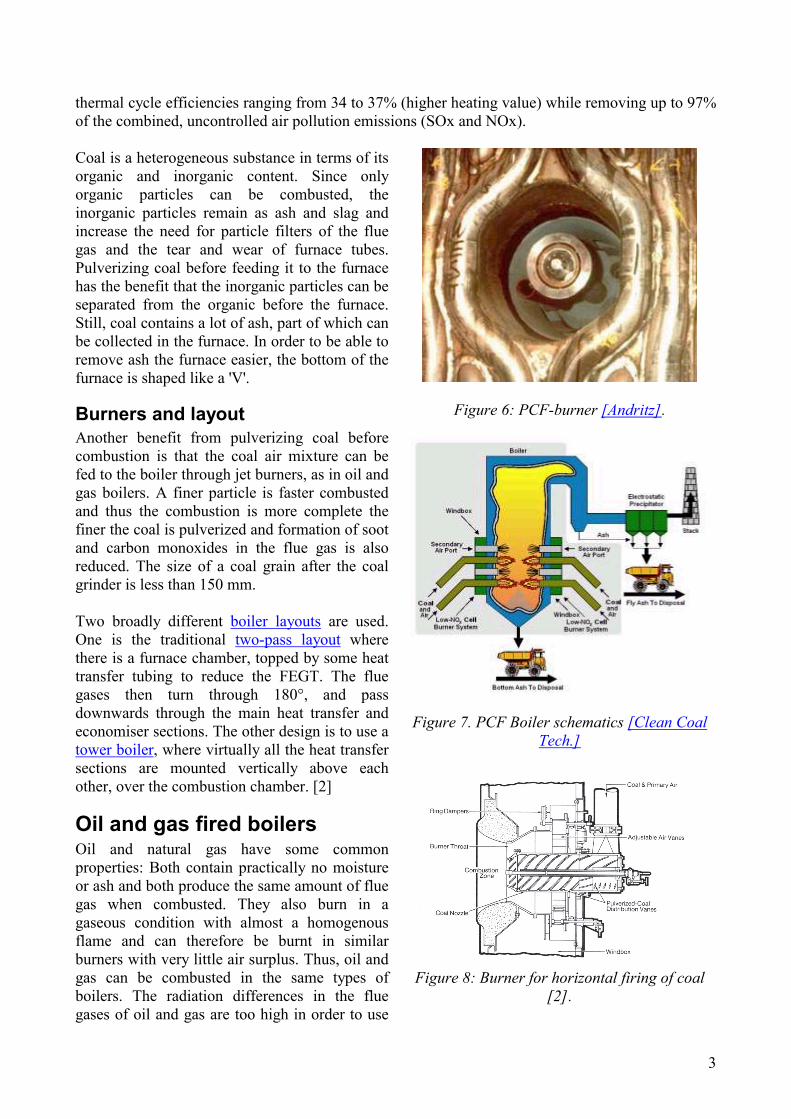
Burners and layout Another benefit from pulverizing coal before combustion is that the coal air mixture can be fed to the boiler through jet burners, as in oil and gas boilers. A finer particle is faster combusted and thus the combustion is more complete the finer the coal is pulverized and formation of soot and carbon monoxides in the flue gas is also reduced. The size of a coal grain after the coal grinder is less than 150 mm. Two broadly different boiler layouts are used. One is the traditional two-pass layout where there is a furnace chamber, topped by some heat transfer tubing to reduce the FEGT. The flue gases then turn through 180°, and pass downwards through the main heat transfer and economiser sections. The other design is to use a tower boiler, where virtually all the heat transfer sections are mounted vertically above each other, over the combustion chamber. [2]
Oil and gas fired boilers Oil and natural gas have some common properties: Both contain practically no moisture or ash and both produce the same amount of flue gas when combusted. They also burn in a gaseous condition with almost a homogenous flame and can therefore be burnt in similar burners with very little air surplus. Thus, oil and gas can be combusted in the same types of boilers. The radiation differences in the flue gases of oil and gas are too high in order to use
Figure 6: PCF-burner [Andritz].
Figure 7. PCF Boiler schematics [Clean Coal Tech.]
Figure 8: Burner for horizontal firing of coal
[2].

4
both fuels in the same boiler. Combusting oil and gas with the same burner can cause flue gas temperature differences up to 100°C.
The construction of an oil and gas boiler is similar to a PCF-boiler, with the exception of the bottom of the furnace, which can be horizontal thanks to the low ash content of oil and gas (Figure 10). Horizontal wall firing (all burners attached to the front wall) is the most affordable alternative for oil and gas burners. [3]
Figure 4: Photo of a flame from a burner combusting oil [2].
Figure 5: Photo of a flame from a burner combusting gas [2].
Figure 9. PCF-boiler with horizontal coal firing
with two-pass layout [2].
Figure 10: Oil or Gas Boiler with horizontal wall firing [Babcock&Borsig].
Fluidized bed boilers
General Fluidized bed combustion was not used for energy production until the 1970's, although it had been used before in many other industrial applications. Fluidized bed combustion has become very common during the last decades. One of the reasons is that a boiler using this type of combustion allows many different types of fuels, also lower quality fuels, to be used in the same boiler with high combustion efficiency. Furthermore, the combustion temperature in a fluidized bed boiler is low, which directly induce lower NOx emissions. Fluidized bed combustion also allows a cheap SOx reduction method by allowing injection of lime directly into the furnace.

5
Principles The principle of a fluidized bed boiler is based on a layer of sand or a sand-like media, where the fuel is introduced into and combusted. The combustion air blows through the sand layer from an opening in the bottom of the boiler. Depending on the velocity of the combustion air, the layer gets different types of fluid-like behaviour, as listed and described in Figure 11. This type of combustion has the following merits:
• Fuel flexibility; even low-grade coal such as sludge or refuse can be burned • High combustion efficiency • Low NOx emission • Control of SOx emission by desulfurization during combustion; this is achieved by
employing limestone as a bed material or injecting limestone into the bed. • Wide range of acceptable fuel particle sizes; pulverizing the fuel is unnecessary • Relatively small installation, because flue gas desulfurization and pulverizing facilities are
not required
FIXED BED BUBBLING TURBULENT CIRCULATING
PARTICLEMASS FLOW
ENTRAINMENTVELOCITY
MIN FLUIDVELOCITY
VELOCITY (LOG)
∆p(LOG)
Figure 11: Regimes of fluidised bed systems [4].
Main types There are two main types of fluidised bed combustion boilers: Bubbling fluidized bed (BFB) and circulating fluidised bed (CFB) boilers. In the bubbling type, because the velocity of the air is low, the medium particles are not carried above the bed. The combustion in this type of boiler is generated in the bed. Figure 12 shows an example of a BFB boiler schematic.

6
The CFB mode of fluidization is characterized by a high slip velocity between the gas and solids and by intensive solids mixing. High slip velocity between the gas and solids, encourages high mass transfer rates that enhance the rates of the oxidation (combustion) and desulfurization reactions, critical to the application of CFB’s to power generation. The intensive solids’ mixing insures adequate mixing of fuel and combustion products with combustion air and flue gas emissions reduction reagents. In the circulating type, the velocity of air is high, so the medium sized particles are carried out of the combustor. The carried particles are captured by a cyclone installed in the outlet of combustor. Combustion is generated in the whole combustor with intensive movement of particles. Particles are continuously captured by the cyclone and sent back to the bottom part of the combustor to combust unburned particles. This contributes to full combustion. The CFB boiler (Figure 13) has the following advantages over the BFB Boiler:
• Higher combustion efficiency • Lower consumption of
limestone as a bed material • Lower NOx emission • Quicker response to load
changes BFB boilers have typically a power output lower than 100 MW and CFB boilers range from 100 MW to 500 MW. In recent years, many CFB boilers have been installed because of the need for highly efficient, environmental-friendly facilities.
Figure 12: Example of a BFB boiler [Foster Wheeler].
Figure 13: Example of a CFB boiler [Foster Wheeler].

7
The world's largest solid biofuel-fired circulating fluidized bed (CFB) boiler (550 MWth) has been built at Alholmens Kraft power plant at Pietarsaari on the west coast of Finland (Figure 14). The CFB boiler with auxiliary equipment and the building was delivered by Kvaerner Pulping Oy and commissioned in autumn 2001.
Internet links • Case Alholmen, Tekes
Combined heat and power (CHP) plants or cogeneration 'Combined heat & power' (CHP) stands for the production of two or more forms of energy from one source of fuel. Cogeneration is a synonym for CHP production and can be divided to industrial cogeneration and utility cogeneration.
Figure 14: Schematic of the CFB boiler at Alholmen. Power output: 550 MWth, Steam parameters: 194
kg/s, 165 bar, 545°C [Kvaerner Pulping Oy]
• Industrial processes need normally saturated steam for heating purposes • Utility CHP plants support usually district heat for a town or city (Figure 15).
The heat load of industrial processes is at higher temperature level than that of district heating plants. In cogeneration plants, the heat load is supplied with backpressure steam from the turbine. The backpressure in industrial applications is at higher level than that in district heating applications. Therefore the electrical efficiency of industrial power plants is usually lower than that of district heating plants since the steam has to stop its expanding at higher pressure. Heat-to-power ratio (equal to the inverse of the finnish ratio called "rakennusaste") is the most important characteristic for co-generation plants. The lower the heat-to-power ratio is with constant overall efficiency; the better is the co-generation process. Heat-to-power ratio depends on the temperature level of the heat load. Thus the heat-to-power ratio of an industrial CHP plant is usually higher than that of a utility CHP plant. With combined cycles a lower value of heat-to-power ratio can be achieved with high overall efficiency. Therefore combined cycle CHP plants (Figure 17) interest energy companies increasingly. The negative side of diesel engine based co-generation plants is the constant heat-to-power ratio. Practically it means that electricity price should be relatively high all the time when plant is operated to provide economical operation of a diesel engine based CHP plant.

8
Figure 15: BFB boiler applied in a CHP power plant, [Härnösand Energi&Miljö Ab, Fortum].
Heat recovery steam generators (HRSG)
Definition As the name implies, heat recovery steam generators (HRSGs) are boilers where heat, generated in
different processes, is recovered and used to generate steam or boil water (Figure 16). The main purpose of these boilers are to cool down flue gases produced by metallurgical or chemical
processes, so that the flue gases can be either further processed or released without causing harm. The steam generated is only a useful by-product. Therefore extra burners are seldom used in
ordinary HRSGs. HRSGs are usually a link in a long process chain, which puts extremely high demands on the reliability and adaptability of these boilers. Already a small leakage can cause the loss of the production for a week. Problems occurring in these boilers are more diverse and more
difficult to control than problems in an ordinary direct heated boiler. Figure 16 shows an example of a HRSG with horizontal layout.
HRSGs in CHP plants CHP is often applied in gas turbine and diesel power plants. Gas turbines and diesels are nowadays commonly used in generating electricity in power plants. The temperature of the flue gases from gas turbines is usually over 400°C, which means that a lot of heat is released into the environment and
9
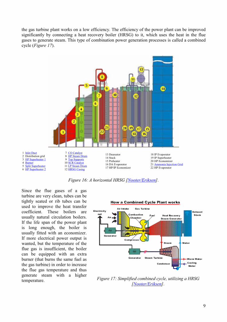
the gas turbine plant works on a low efficiency. The efficiency of the power plant can be improved significantly by connecting a heat recovery boiler (HRSG) to it, which uses the heat in the flue gases to generate steam. This type of combination power generation processes is called a combined cycle (Figure 17).
1 Inlet Duct 2 Distribution grid 3 HP Superheater 1 4 Burner 5 Split Superheater 6 HP Superheater 2
7 CO Catalyst 8 HP Steam Drum 9 Top Supports 10 SCR Catalyst 11 LP Steam Drum 12 HRSG Casing
13 Deareator 14 Stack 15 Preheater 16 DA Evaporator 17 HP/IP Economizer
18 IP Evaporator 19 IP Superheater 20 HP Economizer 21 Ammonia Injection Grid 22 HP Evaporator
Figure 16: A horizontal HRSG [Nooter/Eriksen].
Since the flue gases of a gas turbine are very clean, tubes can be tightly seated or rib tubes can be used to improve the heat transfer coefficient. These boilers are usually natural circulation boilers. If the life span of the power plant is long enough, the boiler is usually fitted with an economizer. If more electrical power output is wanted, but the temperature of the flue gas is insufficient, the boiler can be equipped with an extra burner (that burns the same fuel as the gas turbine) in order to increase the flue gas temperature and thus generate steam with a higher temperature.
Figure 17: Simplified combined cycle, utilizing a HRSG [Nooter/Eriksen].
10
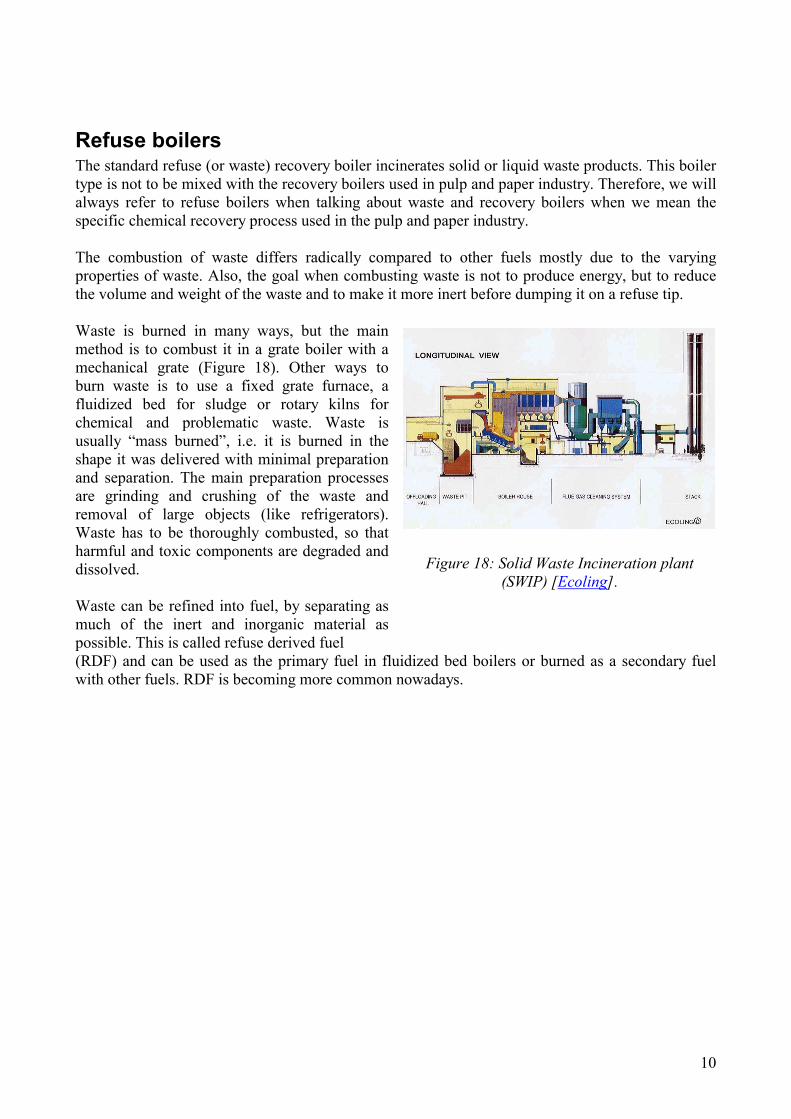
Refuse boilers The standard refuse (or waste) recovery boiler incinerates solid or liquid waste products. This boiler type is not to be mixed with the recovery boilers used in pulp and paper industry. Therefore, we will always refer to refuse boilers when talking about waste and recovery boilers when we mean the specific chemical recovery process used in the pulp and paper industry. The combustion of waste differs radically compared to other fuels mostly due to the varying properties of waste. Also, the goal when combusting waste is not to produce energy, but to reduce the volume and weight of the waste and to make it more inert before dumping it on a refuse tip. Waste is burned in many ways, but the main method is to combust it in a grate boiler with a mechanical grate (Figure 18). Other ways to burn waste is to use a fixed grate furnace, a fluidized bed for sludge or rotary kilns for chemical and problematic waste. Waste is usually “mass burned”, i.e. it is burned in the shape it was delivered with minimal preparation and separation. The main preparation processes are grinding and crushing of the waste and removal of large objects (like refrigerators). Waste has to be thoroughly combusted, so that harmful and toxic components are degraded and dissolved. Waste can be refined into fuel, by separating as much of the inert and inorganic material as possible. This is called refuse derived fuel
Figure 18: Solid Waste Incineration plant (SWIP) [Ecoling].
(RDF) and can be used as the primary fuel in fluidized bed boilers or burned as a secondary fuel with other fuels. RDF is becoming more common nowadays.

11
Recovery boilers All paper is produced from one raw material: pulp. One of the most common methods used to produce pulp is the Kraft process, which consists of two related processes. The first is a pulping process, in which wood is chemically converted to pulp. The second is a chemical recovery process, in which chemicals used in pulping are returned to the pulping process to be used again. The waste liquid, from where chemicals are to be recovered, is called black liquor. The largest piece of equipment in power and recovery operations is the recovery boiler. It serves two main purposes. The first is to "recover" chemicals in the black liquor through the combustion process (reduction) to be recycled to the pulping process. Secondly, the boiler burns the organic materials in the black liquor and produces process steam. Black liquor is injected into the recovery boiler from a height of six meters (Figure 20). The combustion air is injected at three different zones in the boiler. The burning black liquor forms a pile of smelt at the bottom of the boiler,
Figure 19: Recovery boiler schematics
[Andritz].
where complicated reactions take place. The smelt is drained from the boiler and is dissolved to form green liquor. The green liquor is then causticized with lime to form white liquor for cooking the wood chips. The residual lime mud is burnt in a rotary kiln to recover the lime. Energy released by the volatilization of the liquor particles in the recovery boiler yields a heat output that is absorbed by water in the boiler tubes and steam drum. Steam produced by the boiler is utilized primarily to satisfy heating requirements, and to co-generate the electricity needed to operate the various pieces of machinery in the plant.
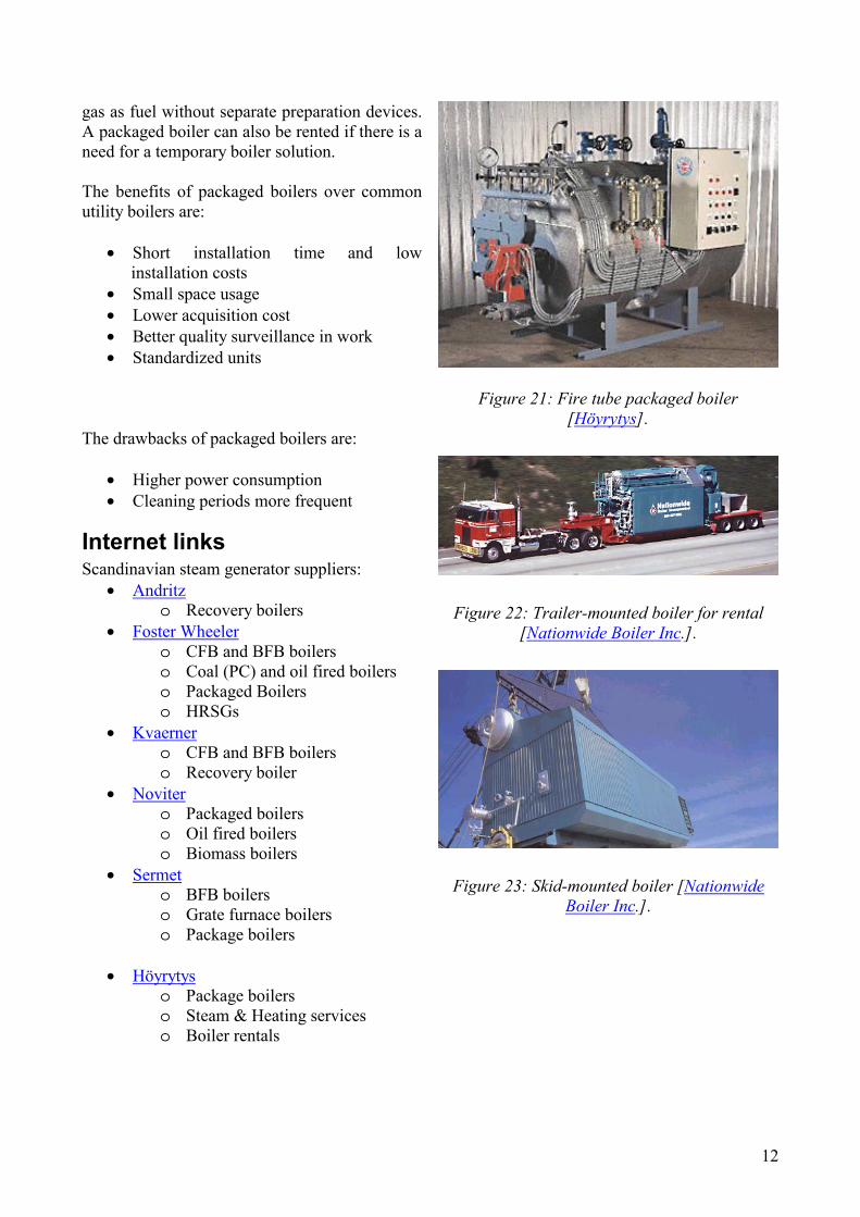
Packaged boilers Packaged boilers are small self-contained boiler units (Figure 21). Packaged boilers are used as hot water boilers, aiding utility boilers and process steam producers. Packaged boilers can be both water tube and fire tube boilers. Packaged boilers can only be used with oil and
Figure 20: Schematics of the furnace of a recovery boiler. The pile on the bottom is the
smelt [Andritz].
12
gas as fuel without separate preparation devices. A packaged boiler can also be rented if there is a need for a temporary boiler solution. The benefits of packaged boilers over common utility boilers are:
• Short installation time and low installation costs
• Small space usage • Lower acquisition cost • Better quality surveillance in work • Standardized units
Figure 21: Fire tube packaged boiler
[Höyrytys]. The drawbacks of packaged boilers are:
• Higher power consumption • Cleaning periods more frequent
Internet links Scandinavian steam generator suppliers:
• Andritz o Recovery boilers
• Foster Wheeler o CFB and BFB boilers o Coal (PC) and oil fired boilers o Packaged Boilers o HRSGs
• Kvaerner o CFB and BFB boilers o Recovery boiler
• Noviter o Packaged boilers o Oil fired boilers o Biomass boilers
• Sermet o BFB boilers o Grate furnace boilers o Package boilers
• Höyrytys
o Package boilers o Steam & Heating services o Boiler rentals
Figure 22: Trailer-mounted boiler for rental [Nationwide Boiler Inc.].
Figure 23: Skid-mounted boiler [Nationwide Boiler Inc.].

13
Other links of interest to this chapter: • Ekokem • Nationwide Boiler Inc • Cyclone fired wet bottom boilers, IEA Coal Research Centre

14
References 1. Demonstration of Coal Reburning for Cyclone Boiler NOx Control, Los Alamos
National Laboratory, Clean Coal Technology Compendium
2. Combustion Engineering. ”Combustion: Fossil power systems”. 3rd ed. Windsor. 1981.
3. Esa Vakkilainen, lecture slides and material on steam boiler technology, 2001
4. CFB Engineering Manual, extract supplied by Foster Wheeler
5. Cyclone fired wet bottom boilers, IEA Coal Research Centre, Web Page, http://www.iea-coal.org.uk/CCTdatabase/cyclone.htm , read 15.8.2002