modern arch bridges in poland – construction...
TRANSCRIPT

MODERN ARCH BRIDGES IN POLAND – CONSTRUCTION METHODS J. Biliszczuk1, 2, R. Toczkiewicz2, J. Onysyk1, 2, W. Barcik2 1Wroc aw University of Technology, Faculty of Civil Engineering, Wroc aw, POLAND. 2Research & Design Office Mosty-Wroc aw, Wroc aw, POLAND. e-mails: [email protected], robert.toczkiewicz @mosty-wroclaw.com.pl, [email protected], wbarcik @mosty-wroclaw.com.pl SUMMARY The road and railway infrastructure in Poland has been intensively developed and modernized for the last years. Around 300 new bridge structures are built annually. This paper presents selected examples of modern arch bridges of different types (bowstring arches, half through arches, upper deck arches) built in recent years in Poland. Main attention is focused on different construction technologies of arch bridges. Keywords: Construction technology, steel bridge, concrete bridge. 1. INTRODUCTION Arch bridges are built with use of a wide variety of construction technologies, adapted to the type of structure, kind of material, type of obstacle and span length. Modern construction methods are among others:
assembly on temporary supports, used when area under the span is easy accessible;
longitudinal launching, used usually for the construction of continuous multi-span beam bridges with the Langer type arch main span;
cantilever method, used for the erection of large-span concrete arch bridges built over wide, deep obstacles (not used in Poland so far);
assembly of spans at a distance from the obstacle, and floating it to the destined place (usually used in the case of crossing wide, navigable waterways, when construction of temporary supports in the water current is inconvenient or impossible).
Selected examples of use of these technologies for the construction of arch bridges built in recent years in Poland, are given below. 2. ASSEMBLY ON TEMPORARY SUPPORTS 2.1. Viaduct near Stryków The viaduct is located along the ring road of Stryków, over the A1 motorway [1]. It is a structure with exposed, originally shaped tied arch girders with a span of 50.0 m. The
529
8th International Conference on Arch Bridges
October 5-7, 2016, Wrocław, Poland

deck is a steel grid composite with a reinforced concrete slab. It consists of longitudinal I-beams, and crossbeams of variable height, spaced every 10.0 m (spacing of bar hangers). Two vertical steel arch girders fixed in the side crossbeams are situated on both sides of the deck, outside its outline. Due to the large skew angle of the viaduct, both arches are offset along each other. The entire steel structure of the viaduct was divided into smaller assembly segments transported by truck. The assembly was carried out using eight temporary supports (towers) of two types – higher and lower. The supports were located at the intersection of the cross-beams with the arch axes (Fig. 1). The towers were braced by I-beams and diagonal rods. Main construction stages of the viaduct included:
erection of the abutments and the temporary supports; placing of the span crossbeams on the auxiliary supports and the side
crossbeams on the abutments; assembly of the longitudinal tie beams and the side segments of the arches; assembly of the top segments of the arches with use of the temporary supports; installation of hangers, replacement of bearings and removal of the temporary
supports; deck slab concreting.
Fig. 1. Views of the viaduct in Stryków in different construction stages [1].
530
Construction technologies

The erection method described above is typical for the construction of short-span structures, when there is easy access to the area below the constructed bridge.
2.2. Bridge over the Vistula River in Pu awy The bridge along the ring road of Pu awy is a part of the S12 expressway. It is a continuous 14-span structure with a 212.0 m long main tied through arch span crossing the Vistula River [2]. Two arch girders, inclined to the bridge axis, have a variable rhomboidal box cross-section. The deck is a steel-concrete composite structure. The tie-beam consists of four plate girders grouped into two tandems. The girders are braced by crossbeams with a regular spacing of 4.0 m. The deck is suspended by 28 units of hangers, each consisting of four tension bars.
Fig. 2. Bridge in Pu awy – main span construction [2] and view of completed bridge.
531
8th International Conference on Arch Bridges
October 5-7, 2016, Wrocław, Poland

Assembly of the deck in the arch span started with the construction of two temporary supports situated in the river bed. The next stage was placing the starting segments on the supports using a floating crane. The rest of the deck consisted of three large sections: two side elements, 42 m long, with the weight of 380 tons, and the middle one with the length of 64 m and the weight of 555 tons [2]. These elements were lifted from the barges using hydraulic jacks (Fig. 2). Segments of the steel arch (two side sections and one middle section) were assembled on the riverside. Each segment together with tower supports was then longitudinally launched on trolleys along the tie beams of the deck (Fig. 2). The total weight of the steel elements placed on the deck exceeded 2700 tons [2]. Side elements of the arch were lifted and rotated, and the middle segment was lifted into the final position, placed on the towers and welded. After connecting the arch segments, the towers were removed from the deck. After tensioning the hangers, the deck was lifted from the supports located in the river. The deck slab was concreted in the last phase. 2.3. Bridge in Milówka The bridge in Milówka is a part of the S69 expressway connecting the city of Bielsko-Bia a and Silesia region with Slovakia. The bridge with a total length of 663 m consists of nine concrete beam spans and three upper deck concrete arches with a span of 103.84 m [3]. The arch girders (two in each span) were erected using large size prefabricated elements with a cross-section of 0.60 × 1.00 (1.40) m, supported during the construction stage on auxiliary supports (Fig. 3). The following assumptions were made:
the precast elements formed side parts of each arch girder to which the formwork of the middle, cast in-situ part of the section was installed;
due to the large weight (up to 36 tons), the precast elements were fabricated on site;
monolithic connections of the precast elements were made in the base nodes of concrete spandrel columns supporting the deck.
Scaffolding under each of the arch spans consisted of six high towers made of steel tubes (Fig. 3). Horizontal diaphragms of the supports, also used as working platforms, were made of reinforced concrete slabs. The upper segments of the supports were braced by cross-beams stiff enough to support the prefabricated concrete elements of the arches. Each arch span consists of 2 × 2 × 7 = 28 prefabricated elements. They were assembled in the direction from the supports to the crown of the arch, using two cranes. Side surfaces of the precast elements and all joints were appropriately prepared to ensure their interaction with cast in-situ concrete [3]. Concrete deck of the bridge in Milówka was constructed with use of a movable scaffolding (Fig. 3). This was convenient due to the inaccessibility of the sloped terrain under the bridge. The bridge in Milówka is at the moment the largest Polish concrete arch bridge.
532
Construction technologies
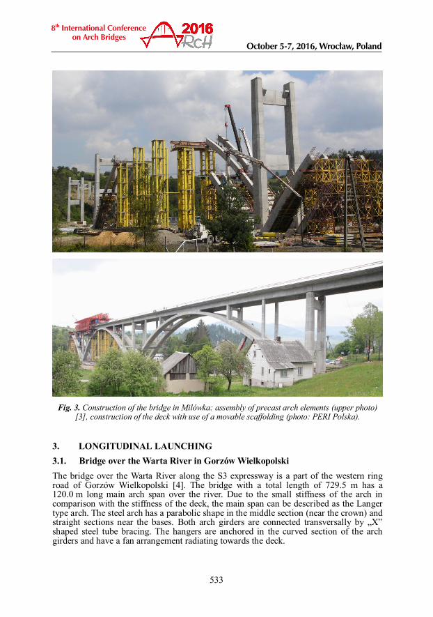
Fig. 3. Construction of the bridge in Milówka: assembly of precast arch elements (upper photo)
[3], construction of the deck with use of a movable scaffolding (photo: PERI Polska).
3. LONGITUDINAL LAUNCHING 3.1. Bridge over the Warta River in Gorzów Wielkopolski The bridge over the Warta River along the S3 expressway is a part of the western ring road of Gorzów Wielkopolski [4]. The bridge with a total length of 729.5 m has a 120.0 m long main arch span over the river. Due to the small stiffness of the arch in comparison with the stiffness of the deck, the main span can be described as the Langer type arch. The steel arch has a parabolic shape in the middle section (near the crown) and straight sections near the bases. Both arch girders are connected transversally by „X” shaped steel tube bracing. The hangers are anchored in the curved section of the arch girders and have a fan arrangement radiating towards the deck.
533
8th International Conference on Arch Bridges
October 5-7, 2016, Wrocław, Poland

Fig. 4. Bridge in Gorzów Wielkopolski – assembly of arch girders and launching the bridge over
the Warta River [4].
Elements of the spans were assembled on the river embankment (Fig. 4). The individual sections with a length of approx. 30 m were transported to the site and welded. Construction technology assumed launching the steel structure of the spans together with the arch, using a temporary support located in the river (Fig. 4). Hangers were installed after the launching was completed. The hangers were anchored using hydraulic jacks located on the temporary support which allowed for lifting or lowering the deck [4]. The hangers were anchored in the direction from the supports towards the centre of the span. After installation of the hangers, the temporary support was removed. Reinforced concrete deck plate was cast in the last stage. 3.2. New Warszawski Bridge in Wroc aw The new Warszawski Bridge is a road-tram urban bridge constructed parallel to the existing barrel vault concrete bridge built in 1916. It is a six-span steel-concrete beam structure. The longest span crossing the water channel is the Langer type arch with a length of 61.89 m. The superstructure consists of two steel box girders composite with a concrete deck slab. The girders have a double-cell box section in the beam spans and a triple-cell box section in the arch span [5]. Steel segments of the spans and the arch were assembled on the embankment and then longitudinally launched (Fig. 5). The launching was conducted with use of a 14.0 m long steel launching nose. Front part of the first launched segment had to be strengthened by a steel truss structure. A single temporary support was located in the water, the longest span during launching was 38 m. The assembly of the steel structure was carried out in the following stages:
in the first step about 70 m long segment was launched using the launching nose;
in the next steps the second segment of the steel structure (60 m long) and the third segment (40 m long) was launched;
in the last stage the longest arch span was assembled – the launching was performed after the arch and hangers had been completely assembled.
534
Construction technologies

Fig. 5. Launching of the new Warszawski Bridge and views of finished structure.
The hangers were tensioned after completion of launching, before removing the temporary support. The last stage of construction was casting the deck plate. The slab has a composite structure consisting of precast panels interacting with a layer of cast in-situ reinforced concrete. The deck slab was concreted in stages: first in the spans, then over the supports [5]. 4. FLOATING OF PREASSEMBLED SPANS 4.1. Father Bernatek Footbridge in Cracow The Father Bernatek Footbridge over the Vistula River is a steel bowstring arch with a span of 148.0 m. The main girder has a circular cross-section. The footbridge has two separate steel orthotropic decks, suspended by net arranged hangers. External tendons acting as a tie-beam were installed under the deck [6]. Construction method of this footbridge was untypical. The whole span was preassembled on temporary supports on the right river bank (Fig. 6). After initial stressing the hangers and tie, the temporary supports were removed. The most difficult construction stage was rotation of the structure into the final position, preceded by the following phases:
construction of the rotational support on the right river bank; construction of temporary supports in the riverbed close to both banks; construction of a special track for moving the span from the river bank onto the
floating support; construction of the floating support on barges.
535
8th International Conference on Arch Bridges
October 5-7, 2016, Wrocław, Poland
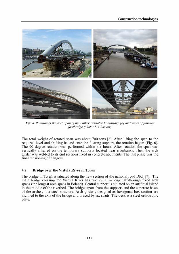
Fig. 6. Rotation of the arch span of the Father Bernatek Footbridge [6] and views of finished
footbridge (photo: . Chamów)
The total weight of rotated span was about 700 tons [6]. After lifting the span to the required level and shifting its end onto the floating support, the rotation begun (Fig. 6). The 90 degree rotation was performed within six hours. After rotation the span was vertically alligned on the temporary supports located near riverbanks. Then the arch girder was welded to its end sections fixed in concrete abutments. The last phase was the final tensioning of hangers. 4.2. Bridge over the Vistula River in Toru The bridge in Toru is situated along the new section of the national road DK1 [7]. The main bridge crossing the Vistula River has two 270.0 m long half-through fixed arch spans (the longest arch spans in Poland). Central support is situated on an artificial island in the middle of the riverbed. The bridge, apart from the supports and the concrete bases of the arches, is a steel structure. Arch girders, designed as hexagonal box section are inclined to the axis of the bridge and braced by six struts. The deck is a steel orthotropic plate.
536
Construction technologies

Fig. 7. Bridge in Toru - assembly of steel arches using floating temporary supports (photo:
K. J drzejewski, Strabag) and view of completed bridge.
The method of construction assumed assembling the whole structure of the arches on the river bank and floating it to the destined place [7]. The arches were assembled from the sections with a length of approx. 10 m. Due to the high rise of the arch, it was divided into two elements (half-arches). After assembling, the half-arches were moved, hingedly connected, lifted using a special tower (Fig. 7) and butt welded in the crown. The most complex stage of the construction was the water transport of the arches from the construction site to the concrete supports. It required to use two floating supports (pontoons with gantries), connected with the transported arch by a system of rod stays (Fig. 7). The arches were alligned to the steel end segments encased in concrete supports. The arch-support connection required activities related to the elimination of the hinge effect in the joints (i.a. ballasting) [7]. The deck was assembled from 30 m long segments of the full cross-section of the bridge deck. The segments were lifted from pontoons in the direction from the supports towards the mid-span. After adjustments of hangers, the deck segments were butt welded. 5. CONCLUSIONS This paper presents selected projects of arch bridges executed in recent years in Poland. A whole range of modern technologies was used in the construction of described bridges, starting from the most common construction method – use of temporary supports. Among described examples a special attention should be paid to the construction with the use of large-size elements, even the whole preassembled spans.
537
8th International Conference on Arch Bridges
October 5-7, 2016, Wrocław, Poland

REFERENCES [1] BILISZCZUK J., BARCIK W., ONYSYK J., PRABUCKI P., SU KOWSKI M.,
SZCZEPA SKI J., TOCZKIEWICZ R., TUKENDORF K., Highway arch viaducts in Poland, Proc. of 7th International Conference on Arch Bridges, Trogir – Split, 2-4 October 2013, pp. 367-374.
[2] B K J, GREJ K, OLEKSIAK C, SA ACH W., Bridge over the Vistula River in Pu awy – construction technology (in Polish), Proc. of symposium Wroc awskie Dni Mostowe “Mosty stalowe. Projektowanie, technologie budowy, badania, utrzymanie”, Wroc aw, 27-28 November 2008, pp. 95-107.
[3] MARCINKÓW A., Producibility of arch bridges construction with application of partial prefabrication (in Polish), Proc. of symposium Wroc awskie Dni Mostowe “Technologiczne aspekty w projektowaniu i budowie mostów betonowych”, Wroc aw, 23-24 November 2006, pp. 183-197.
[4] TOPOLEWICZ K., Arch bridge over the Warta River in Gorzów Wielkopolski (in Polish), Proc. of symposium Wroc awskie Dni Mostowe „Mosty stalowe. Projektowanie, technologie budowy, badania, utrzymanie”, Wroc aw, 27-28 November 2008, pp. 163-170.
[5] BILISZCZUK J, BARCIK W, ONYSYK J, PRABUCKI P, SADOWSKI K., New Warsaw Bridge over the Odra River in Wroc aw, Proc. of 7th International Conference on Arch Bridges, Trogir – Split, 2-4 October 2013, pp. 375-382.
[6] SIWOWSKI T., Ó TOWSKI P., Ó TOWSKI K., BILISZCZUK J., The new arch footbridge over Vistula River in Cracow, Proc. of 4th International Conference Footbridge 2011, Wroc aw, 6-8 July 2011, pp. 234-235.
[7] W CHALSKI K., CYWI SKI Z., Die neue Straßenbrücke in Toru , Polen – Teil 1: Planung und Bau, Stahlbau, Vol. 84, No. 4, 2015, pp. 267–274.
538
Construction technologies