models sl2-g312-1, sl2-g312-1b, sl2-g312-v2 … sl2-g312-1, sl2-g312-1b, sl2-g312-v2 operations...
TRANSCRIPT
Sutron Corporation | 22400 Davis Drive | Sterling, VA 20164 | 703.406.2800 | www.sutron.com | [email protected]
SatLink2 Logger / Transmitter Models SL2-G312-1, SL2-G312-1B, SL2-G312-V2
OPERATIONS & MAINTENANCE MANUAL
Part No. 8800-1149Rev. 7.37
April 4, 2013
2
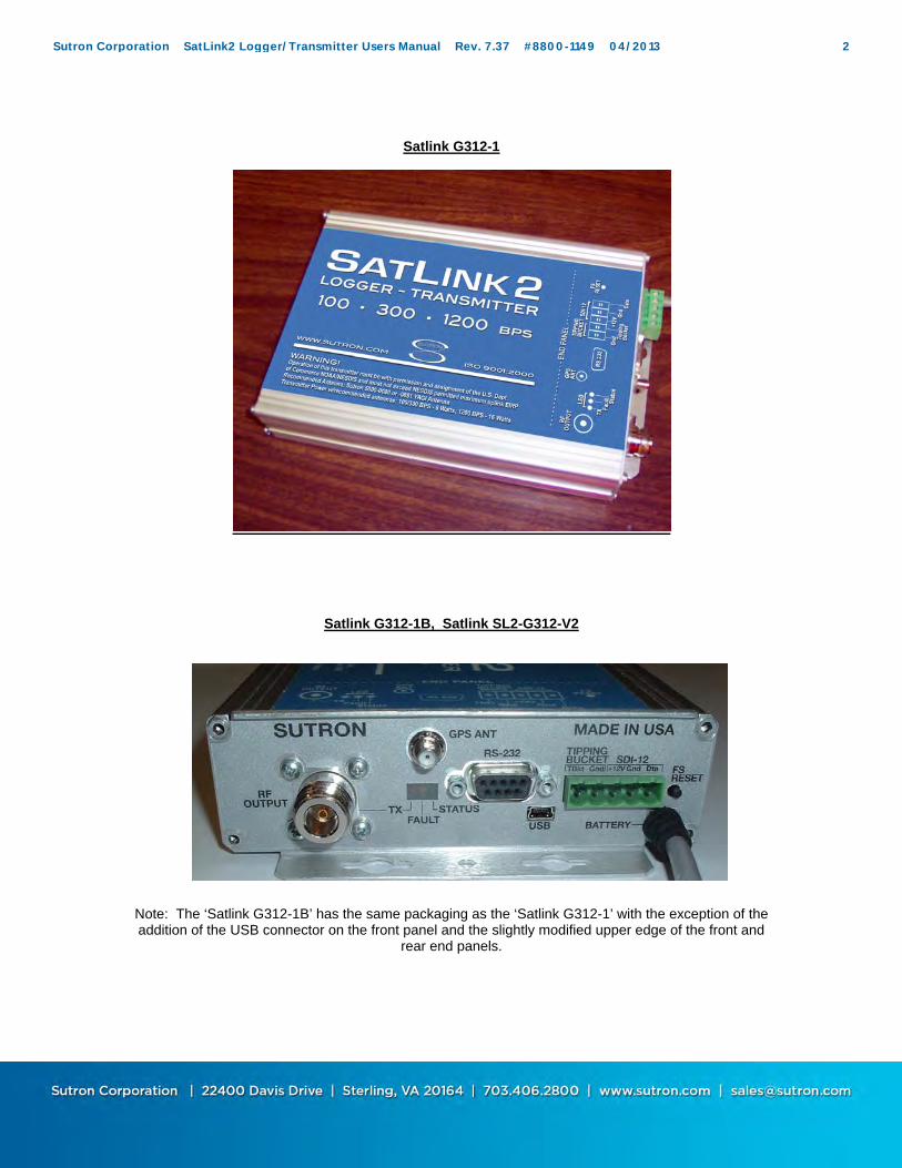
Satlink G312-1
Satlink G312-1B, Satlink SL2-G312-V2
Note: The ‘Satlink G312-1B’ has the same packaging as the ‘Satlink G312-1’ with the exception of the addition of the USB connector on the front panel and the slightly modified upper edge of the front and
rear end panels.
Sutron Corporation SatLink2 Logger/Transmitter Users Manual Rev. 7.37 #8800-1149 04/2013 2
Table of Contents
CHAPTER 1: INTRODUCTION ......................................................................................................................... 7
PRODUCT DESCRIPTION ....................................................................................................................... 8 Satlink 2 (Model Satlink SL2-G312-V2) (Manufactured 2011- current) .............................................. 8 Satlink 2 (Model Satlink SL2-G312-1B) (Manufactured 2009- current) .............................................. 8 Satlink 2 (Model Satlink G312-1) (Manufactured 2004- 2009) ............................................................. 8 Satlink Logger (Manufactured 2001-2004) ........................................................................................... 9
FEATURES .............................................................................................................................................. 10 Key Features ......................................................................................................................................... 10 Specifications ....................................................................................................................................... 11
CHAPTER 2: GETTING STARTED ................................................................................................................ 13
UNPACKING ............................................................................................................................................... 14 Standard Items ...................................................................................................................................... 14 Common Optional Items ...................................................................................................................... 14
INITIAL CHECKOUT ................................................................................................................................... 15 Required Equipment ............................................................................................................................. 15 Proceed with these steps to install the software and check out Satlink: ............................................... 15
CHAPTER 3: UNDERSTANDING SATLINK LOGGER HARDWARE ..................................................... 16
FRONT PANEL CONNECTIONS: ......................................................................................................... 17 RS-232 Connector ................................................................................................................................ 17 USB Connector ..................................................................................................................................... 17 Front Terminal Strip ............................................................................................................................. 18 Tipping bucket ...................................................................................................................................... 18 SDI-12 .................................................................................................................................................. 18 GPS Antenna Connector ....................................................................................................................... 18 RF Output Connector ........................................................................................................................... 18 Status LED (Green) ............................................................................................................................. 18 Fault LED (Yellow) ............................................................................................................................. 19 Tx LED (Red) ....................................................................................................................................... 19 Failsafe Reset Button ............................................................................................................................ 19 Analog Inputs 1- 4 ................................................................................................................................ 19 2.5 V Reference .................................................................................................................................... 20 Analog Ground ..................................................................................................................................... 20 +12V Switched Power .......................................................................................................................... 20 +12 SWITCHED GROUND ................................................................................................................ 20 EARTH GROUND LUG ...................................................................................................................... 20
RF POWER INFORMATION: ................................................................................................................. 21 TRANSMIT POWER ........................................................................................................................... 21 ADJUSTMENT OF POWER ............................................................................................................... 21 RF BOOSTER AMPLIFIERS .............................................................................................................. 21 FORWARD AND REFLECTED POWER .......................................................................................... 21 DC INPUT POWER ............................................................................................................................. 23
CHAPTER 4 UNDERSTANDING SATLINK LOGGER OPERATIONS .................................................... 24
OVERVIEW ................................................................................................................................................ 25 What Satlink Front Panel Lights Indicate ............................................................................................. 25 Running and Stopped ........................................................................................................................... 25 Configuring Satlink Logger .................................................................................................................. 26 Understanding Transmisssions ............................................................................................................. 26 Data Buffers ......................................................................................................................................... 27
Sutron Corporation SatLink2 Logger/Transmitter Users Manual Rev. 7.37 #8800-1149 04/2013 3

Understanding Measurements .............................................................................................................. 27 SDI Clock Synchronization .................................................................................................................. 28 System Malfunction .............................................................................................................................. 28
CHAPTER 5 USING SATLINK LOGGER COMMUNICATOR .................................................................. 29
OVERVIEW ................................................................................................................................................ 30 Understanding Satlink Setups and How Communicator Talks to Satlink ............................................ 30 Communicator (PC) Startup screen ...................................................................................................... 31 Satlink Logger Quick View Status (PC Only) ...................................................................................... 32 Communicator (PC) Menus .................................................................................................................. 36 Password Protection ............................................................................................................................. 37 USB Port Driver Issue with Microsoft Windows ................................................................................. 38 INSTRUCTIONS FOR DRIVER INSTALLATION FOR COMPUTER OPERATION WITH MAXIMUM OF SEVERAL SATLINK2s. .......................................................................................... 39 INSTRUCTIONS FOR SYSTEM VARIABLE MODIFICATIONS PRIOR TO DRIVER INSTALLATION FOR COMPUTERS OPERATING WITH LARGE NUMBER OF SATLINK2s. 39 Edit Registry. ........................................................................................................................................ 39 Enable Windows to Display Hidden (Phantom) Virtual Com Port Assignments. ................................ 40 SatComm (PocketPC) Specifics ........................................................................................................... 40 SatComm Startup and Operation .......................................................................................................... 40 SatComm Menus .................................................................................................................................. 41 Using a Modem .................................................................................................................................... 42 Using Bluetooth .................................................................................................................................... 43 Using SatComm with Optional Serial Cards ........................................................................................ 43
MAIN ......................................................................................................................................................... 44 Get Status/Refresh ................................................................................................................................ 45 Clear Status ........................................................................................................................................... 45 Reset Failsafe........................................................................................................................................ 45 Quick Status ......................................................................................................................................... 46 Firmware Version ................................................................................................................................. 46
MEASUREMENTS ....................................................................................................................................... 47 General Measurement Settings ............................................................................................................. 48 Label ..................................................................................................................................................... 48 Active ................................................................................................................................................... 48 Send to Log .......................................................................................................................................... 49 Right Digits .......................................................................................................................................... 49 Schedule: Time and Interval ................................................................................................................. 49 Relative to Transmission ...................................................................................................................... 49 Averaging ............................................................................................................................................. 49 MinMax ................................................................................................................................................ 50 Measurement Type Settings ................................................................................................................. 52 Tipping Bucket Accumulation .............................................................................................................. 52 SDI-12 .................................................................................................................................................. 52 Manual Entry ........................................................................................................................................ 53 8400 ...................................................................................................................................................... 53 Battery Voltage ..................................................................................................................................... 54 Analog .................................................................................................................................................. 54 Satlink Temperature ............................................................................................................................. 55 Tipping Bucket Rate ............................................................................................................................. 55 Processing ............................................................................................................................................. 56 Slope and Offset ................................................................................................................................... 56 Equation ................................................................................................................................................ 56 Transmissions and Measurements ........................................................................................................ 58 Measurement Alarm Settings ............................................................................................................... 58 Last Data ............................................................................................................................................... 60
Sutron Corporation SatLink2 Logger/Transmitter Users Manual Rev. 7.37 #8800-1149 04/2013 4
Measurement Commands ..................................................................................................................... 61 DATA ........................................................................................................................................................ 63
Logging Functions ................................................................................................................................ 64 To get log files from the Pocket PC device onto another computer ..................................................... 66 Graphing ............................................................................................................................................... 67
SCHEDULED TX ......................................................................................................................................... 69 300 BPS ................................................................................................................................................ 72 Transmission Channel Settings ............................................................................................................ 73 1200 BPS .............................................................................................................................................. 74 Data Formatting .................................................................................................................................... 75 User Initiated Transmissions ................................................................................................................ 76 Data Buffers (Communicator Only) ..................................................................................................... 76 Transmission Message (Communicator Only) ..................................................................................... 77
ADVANCED SCHEDULED TX SETTINGS ...................................................................................................... 79 Dumb Logger Mode ............................................................................................................................. 80
RANDOM TX .............................................................................................................................................. 81 TRANSMITTER TEST (COMMUNICATOR ONLY) .......................................................................................... 83 GPS ........................................................................................................................................................... 85
V2.0 Certification impact to Satlink ..................................................................................................... 88 SEND TO SUTRON (SATCOMM TEST) ........................................................................................................ 89
Satellite Test Channels ......................................................................................................................... 91 DIAGNOSTIC (COMMUNICATOR ONLY) ..................................................................................................... 92 UPGRADING SATLINK FIRMWARE .................................................................................................. 95 SATELLITE AIMING FEATURE ........................................................................................................... 96 FAILSAFE RESET ........................................................................................................................................ 98
CHAPTER 6 INSTALLATION ......................................................................................................................... 99
PROCEDURE..............................................................................................................................................100 Stand Alone Installation ......................................................................................................................100 8210 Internal Installation .....................................................................................................................102 8210 External Installation ....................................................................................................................102 Xpert Installation .................................................................................................................................103 Optional Items .....................................................................................................................................103
CHAPTER 7 MAINTENANCE AND TROUBLESHOOTING .................................................................... 104
TROUBLESHOOTING .................................................................................................................................105 Q: How can I troubleshoot my Satlink Logger site? ............................................................................105 Q: Why will my Satlink Logger not turn on? ......................................................................................105 Q: The LED on the front panel blinks, but the Communicator still cannot find Satlink Logger? .......105 Q: Why is my sensor not recording data at all? ...................................................................................106 Q: Why is Satlink Logger occasionally skipping measurements? .......................................................106 Q: Satlink Logger is making measurements correctly, but why am I receiving wrong values? ..........106 Q: The internal/external measurements are fine, but why isn't Satlink Logger transmitting the data? 106 Q: Why does the transmission contain M’s or /// in place of data? .....................................................107 Q: Why does Satlink fail the first transmission after bootup? .............................................................107
STATUS AND ERROR MESSAGES ...............................................................................................................108 SELF TESTS ..............................................................................................................................................111
CHAPTER 8 COMMAND LINE ................................................................................................................... 114
SATLINK COMMAND LINE ........................................................................................................................115 Set up ...................................................................................................................................................115 Wake up ...............................................................................................................................................115 Initiating command line .......................................................................................................................115 Issuing commands ...............................................................................................................................115 Commands supported ..........................................................................................................................115
Sutron Corporation SatLink2 Logger/Transmitter Users Manual Rev. 7.37 #8800-1149 04/2013 5

Machine mode .....................................................................................................................................115 Downloading the log ...........................................................................................................................115 Log format ...........................................................................................................................................116 Terminating the connection .................................................................................................................116 Session example ..................................................................................................................................117
APPENDICES .................................................................................................................................................... 118
APPENDIX A: OPERATION WITH SUTRON 8210 .......................................................................................119 Summary of Features/Changes ............................................................................................................119 Hardware Interface Requirements .......................................................................................................120 Connecting the 8210 to Satlink Logger ...............................................................................................120 GPS Time Synchronization .................................................................................................................120 8210 Switch Settings ...........................................................................................................................120 8210 Software Requirements ...............................................................................................................121 GOES Radio Setup Menu ....................................................................................................................121 Inspect System Status Screen ..............................................................................................................121 Front Panel GOES Radio Setup Changes ............................................................................................123 Front Panel Inspect System Menu Changes ........................................................................................123
APPENDIX B: OPERATION WITH SUTRON XPERT ......................................................................................124 Control Panel .......................................................................................................................................124 Setup ....................................................................................................................................................124
APPENDIX D: MORE ABOUT SDI-12 .........................................................................................................125 Overview .............................................................................................................................................125 Wiring ..................................................................................................................................................125 Connector ............................................................................................................................................126 SETUP of SDI sensors ........................................................................................................................126 Useful SDI commands .........................................................................................................................126
APPENDIX E: DATA TRANSMISSION FORMATS .........................................................................................127 RANDOM TRANSMISSION PSEUDOBINARY DATA FORMAT ................................................127 SCHEDULED PSEUDOBINARY DATA FORMAT ........................................................................129 SCHEDULED SHEF DATA FORMAT .............................................................................................131 SIX-BIT BINARY ENCODED FORMAT .........................................................................................133 ASCII COLUMN FORMAT ...............................................................................................................134 ASCII SENSOR FORMATTING .......................................................................................................135 DATA RECEIVED THROUGH DAPS ..............................................................................................136
APPENDIX F: VERSION HISTORY ................................................................................................................137 APPENDIX G: GOES CHANNEL DEFINITION ............................................................................................143 APPENDIX H: METEOSAT .....................................................................................................................152 APPENDIX I: INSAT ..............................................................................................................................154 APPENDIX J: 40 WATT SATLINK VARIANT (SL2-B40W-1) .................................................................157 APPENDIX K: MOUNTING PATTERN ........................................................................................................159 APPENDIX L: ARGOS ............................................................................................................................160
INDEX ................................................................................................................................................................ 161
Sutron Corporation SatLink2 Logger/Transmitter Users Manual Rev. 7.37 #8800-1149 04/2013 6

Chapter 1: Introduction
Sutron Corporation SatLink2 Logger/Transmitter Users Manual Rev. 7.37 #8800-1149 04/2013 7

PRODUCT DESCRIPTION
Satlink 2 (Model Satlink SL2-G312-V2) (Manufactured 2011- current) This model Satlink is an updated version of the SL2-G312-1B that meets the new NESDIS certification standards CS-V2.0. These are the newest NESDIS standards upgraded in 2009 that support the doubling of the channels and new transmit filters among other small details. Below are key differences:
Doubling of the number of 300 bps channels by reducing the existing channel width in half and adding new channels in between the original channels.
Redefining the channel numbering schemes for 1200 bps. Improved frequency control for longer operation without GPS reception. Reduced power output to comply with lower power requirements on the satellite. Ability to select the satellite antenna from a list which controls the output power. Elimination of Domestic 100 bps operation. Reduction of CGMS (international 100bps) channels to 11. Added Antenna Aim calculator support for Satlink Communicator. Reduction in the maximum transmit buffer length.
Satlink 2 (Model Satlink SL2-G312-1B) (Manufactured 2009- current) Satlink 2 (Model Satlink G312-1B) is an improved version of the Satlink2 that preceded it. It is virtually the same product with the following improvements:
Addition of a USB Mini-Type B port designed for connection to computers that no longer are equipped with RS-232 ports. NOTE: The USB connection is designed to only support RS-232 over USB communication and does NOT support any USB type device such as external memory sticks or USB modems. Modem and USB card support are currently supported on the Satlink Display option.
Modified endpanels that have been strengthened and gasket material has been added to improve the sealing of the Satlnk enclosure. The same mounting footprint may be used as that used on the previous Satlink G312-1 product, however, if a Satlink 2 (Satlink G312-1B) is stacked with a 9210 product, a modified bracket set must be used to stack the new Satlink with the 9210.
The internal RTC (real time clock) now has a battery backup preventing the loss of the day/date and time upon the removal or reset of external DC battery power. Note that the lithium battery is designed to operate over the expected life of the product and is not user serviceable.
Satlink 2 (Model Satlink G312-1) (Manufactured 2004- 2009) Satlink 2 (Model Satlink G312-1) is an improved version of Sutron’s popular Satlink Logger. It is 100% backwards compatible and can do everything that Satlink Logger can. It is built on a modified hardware platform and features a lot of the same software. New features include the ability to make analog measurements on multiple channels. Satlink 2 comes in a slightly smaller package and has three LEDs on the front for status indication.
Sutron Corporation SatLink2 Logger/Transmitter Users Manual Rev. 7.37 #8800-1149 04/2013 8

Satlink Logger (Manufactured 2001-2004) Satlink Logger is Sutron’s multi-satellite data logger and transmitter that can be used to relay data through environmental satellites. For over 25 years, Sutron Corporation has been the leader in the design, manufacture, and support of satellite transmitters and data acquisition stations. Satlink Logger builds upon Sutron’s vast experience of delivering over 25,000 field stations to customers around the world. Satlink Logger will be the reliable communications device of thousands of systems in the years to come. Satlink Logger /Satlink 2 is designed to operate on the following satellites:
GOES Domestic 100, 300, 1200 bps, timed and random reporting GOES International Meteosat, MSG (Meteosat Second Generation) 100 bps channels, timed and alert reporting GMS 100 bps domestic and international channels INSAT 4800 bps domestic channels FY2B 100 bps domestic channels ARGOS/SCD
Because of its advanced digital design, Satlink Logger has the flexibility to support the different satellites’ special modulation and spectral requirements. Satlink Logger is a stand-alone logger and transmitter. For many simple stations, Satlink Logger can make the measurements, log, format and transmit the data. The built-in SDI-12 interface gives Satlink Logger the ability to make measurements of a wide range of sensors including water level, water quality, wind, and temperature. Satlink 2 features multiple analog channels and allows the user to setup a variety of measurement configurations including differential and ratiometric. The built-in tipping bucket interface allows easy measuring of precipitation. Satlink Logger supports multiple independent measurement schedules. After making measurements, Satlink Logger can perform complex equation processing on the measured data. This allows the user to convert analog voltage readings into meaningful units such as temperature. Satlink can log the data into its secure flash memory. The log in Satlink Logger is capable of holding over 120,000 readings. If there is ever any problem retrieving the data through the satellite, the data can always be retrieved from the log memory through a fast serial download. As a stand-alone logger/transmitter, Satlink Logger supports both scheduled transmissions and Sutron’s popular adaptive random reporting transmissions. Scheduled transmissions can be configured for any satellite and the data can be formatted in SHEF or Pseudobinary formats. After each measurement is made, the data is tested and used to control random transmissions. Random transmissions can be configured to make frequent transmissions, when the data are changing rapidly or are in alarm conditions, and infrequent transmissions when the data are not in alarm. Satlink Logger is typically set up by a PC or IPAQ Pocket PC running software provided by Sutron. This software makes it simple to configure Satlink Logger to collect, process, log, and transmit the desired data. Satlink Logger can also be used connected to a Sutron 9210, 8210 or Xpert. These data recorders are capable of making their own measurements and formatting their own data for transmission. Satlink Logger offers Data Merge Mode in which Satlink Logger will combine data it collected from sensors with the data formatted by other recorders in a transmission. Sutron’s Xpert and 8210 are “Satlink Logger aware” meaning you can set up Satlink Logger transmissions through the Xpert or 8210 without using Satlink Logger Communicator. This seamless integration makes a system that is easy to operate and use. (Note that you need to use Satlink Logger Communicator to set up Satlink Logger’s measurement functions.)
Sutron Corporation SatLink2 Logger/Transmitter Users Manual Rev. 7.37 #8800-1149 04/2013 9
FEATURES
Key Features User programmable from a pocket PC, desktop PC, or laptop PC via
a simple visual screen (screens on page 2) Built-in logger - 120,000 readings from any sensor to Flash Memory 4 Analog Inputs for single-ended & differential input sensors Gain setting options on Analog inputs SDI-12 support facilitates adding a vast array of sensors Dedicated Tipping Bucket input Powerful mathematical equation editor for analog sensor data
conversion with polynomial and trigonometric support Reference voltage output for direct thermistor support Switched +12Vdc output Unique front panel LED indicators for critical “health” information at
a glance Forward and reflected RF power measured. Both scheduled & random (event driven) reporting & alarm
detection Easy Data Merge allows Satlink to make & log its own
measurements AND receive data from another logger Every unit includes Trimble GPS module with fast satellite
acquisition Internal flash log can be downloaded @ 115200 Baud. Standard RS232 interface to data recorder Easy integration with Sutron 8210, 8080 Xpert, 9210 XLite, 8400 &
8200 Dataloggers Serial port for quick and easy firmware & field software upgrades Internal diagnostics to monitor transmission quality and GPS
Performance
Sutron Corporation SatLink2 Logger/Transmitter Users Manual Rev. 7.37 #8800-1149 04/2013 10
Specifications Weight: 2.2 lbs. Size: 5.55 in. x 7.70 in. x 1.75 in. Environmental: -40°C to +60°C Operating Voltage: 10.4 to 15 VDC, reverse voltage protected LED Indicators
Status Fault Transmit
Connections Power: Built-in cable GPS: SMA (Bulkhead Mounted) RS-232: DB9 SDI-12: 3 position removable terminal strip Tipping Bucket: 2 position removable terminal strip Analog input: 8 position removable terminal strip RF: N-Type
Interface Protocol Sutron Satlink Logger protocol Supports other DCPs in dumb logger mode at 9600 baud
Measurements Supports 16 sensors or measurements Independent measurement schedules for each sensor Analog Inputs: 4 channels (single ended 0-5V, differential, or ratiometric) Tipping Bucket: Dedicated switch closure counter input SDI-12: V1.0, V1.1, V1.2, V1.3 sensors User enterable labels for sensors Powerful Mathematical Equation Editor for analog sensor data Equation processing allows user entry of virtually any equation Manually entered readings
Analog measurement specifications A/D Resolution: 24 bit A/D converter A/D Accuracy: +/- 0.02% FS @ 25°C, +/- 0.03% FS when Transmitting Temperature Coeff: +/- 5 ppm/C typ. +/- 10 ppm/C max Linearity: +/- 0.005% FS Reference Output: 2.5 Volt, 10 ma. max (for temperature sensors) Switched +12V Out: 500 ma. Max
Log 120,000 floating point readings Individual time stamps to 1 second Can log numbers as small as 1E-38 or as large as 3E+38 (IEEE32 float) Non-volatile flash memory Quality flag for each value
Data Data Merge Mode supports merging of Satlink Logger data with data from external logger prior to
transmission Circular Buffer Mode - enhanced transmission data management. Excess data is stored & sent
on subsequent transmissions. Alarms
User configurable for each sensor Alarm types: high alarms, low alarms, and rate of change alarms
Timekeeping
Sutron Corporation SatLink2 Logger/Transmitter Users Manual Rev. 7.37 #8800-1149 04/2013 11

Sync to GPS within 10 ms Frequency discipline to within 10Hz
Power Requirements @ 12.5 VDC Quiescent: 6 mA typ 300 BPS Transmission: 3.8 A (Typ) 1200 BPS Transmission: 4.8 A (Typ) Protection against open or short circuit loads on transmitter output
(Note SL2-G312-V2 current draw is dependent on a antenna selected which in turn selects the output RF power. )
Recommended Antenna Sutron YAGI (10.5 dB gain), 5000-0080
Transmission Modes 100 BPS random and scheduled 300 BPS random and scheduled 1200 BPS scheduled 4800 BPS INSAT selectable 10 min. window (3 randomized repeat sequence) METEOSAT Alert & Self Timed ARGOS/SCD Format
Transmission Character Sets ASCII Pseudobinary
Transmitter Output Power (SL2-G312-1B) Software selectable power levels 7 Watt nominal, 100/300 BPS (+/- 1dB) 14 Watt nominal 1200 BPS (+/- 1 dB) 3.5 watt (adjustable to 18 watt) INSAT
Transmitter Output Power (SL2-G312-1B)
Software selectable power levels 1.25/2.5/5/7 Watt nominal, 300 BPS (+/- 1dB) 2.5/5/10/14 Watt nominal 1200 BPS (+/- 1 dB) 3.5 watt (adjustable to 18 watt) INSAT
Sutron Corporation SatLink2 Logger/Transmitter Users Manual Rev. 7.37 #8800-1149 04/2013 12

Chapter 2: Getting Started
Sutron Corporation SatLink2 Logger/Transmitter Users Manual Rev. 7.37 #8800-1149 04/2013 13

UNPACKING
Standard Items Satlink Logger is shipped with the following: Diskette with Satlink Logger Communicator and SatComm Pocket PC programs GPS antenna with 5M cable Spare fuse (3AG, 8 AMP, slow blow) Terminations for the power cable Manual Superior customer service Superior performance, features, and value
Common Optional Items M-F DB9 cable Mini USB Type B (M) to USB Type A(M) M-M Null Modem Gender Changer (Sutron part number 3121-1700) (used with IPAQ Pocket PC) Sutron YAGI antenna Sutron 15-foot RG-8 antenna cable SMA-male cable to N-type female bulkhead cable for mounting in most enclosures Lightning arrestor for RF output cable Extension cable for GPS antenna Solar panel w/ regulator Battery Grounding cable kits
Sutron Corporation SatLink2 Logger/Transmitter Users Manual Rev. 7.37 #8800-1149 04/2013 14
INITIAL CHECKOUT
The initial checkout is intended to confirm that Satlink Logger is operational.
Required Equipment You will need the following equipment to operate a Satlink Logger. Some of these items are available from Sutron as optional ancillary equipment: A 12-volt battery or power supply capable of supplying around 5 amps. A battery capacity of 24 amp hours is recommended as a minimum. Although smaller capacity batteries will function, the batteries may run low over extended periods in which the sun does not reach the solar panel. This may be experienced in applications in which snow accumulation is significant or when stations are installed in high latitude locations having shortened sunlight coverage. An RF output cable to connect to an SMA - female output connector A "dummy" 50 ohm load or a wattmeter with a 50 ohm load capable of 25 watts min A PC with a serial port and a M-F Serial Cable (Sutron part 6411-1484) or A Pocket PC (e.g. Compaq IPAQ) with a Serial Sync cable and a M-M Null modem adapter (Sutron part 3121-1700)
Proceed with these steps to install the software and check out Satlink:
Copy Satlink Logger Communicator to a PC. Connect the PC serial port to Satlink Logger's RS232 port.
Or connect the PocketPC to your PC and run the setup program (e.g., SatCommPPCSetup2003.exe) provided by Sutron and follow the instructions. After SatComm is installed, connect the PocketPC to Satlink using the serial sync cable and M-M null modem adapter.
Connect the GPS antenna to the connection labeled GPS. Connect the dummy load or wattmeter to the connection labeled “RF OUTPUT”.
Connect Satlink Logger's power cable to a 12-volt battery or suitable power supply. You will see the “STATUS” light flash several times during its startup sequence. The LEDs will light up in sequence: first the green, then the yellow and finally the red. After the startup is finished, all LEDs will turn off. The green LED will then flash every 5 seconds if Satlink is running, or every 10 seconds to indicate that it is stopped.
Run Satlink Logger Communicator program on the PC. Choose to work in “connected” mode. The program will notify you if it has communicated with Satlink.
Or run SatComm on the PocketPC. If you see status information in the “System Status” box, the program has communicated with Satlink.
Your Satlink Logger is operating and ready to be configured. Proceed to chapter 3.
Sutron Corporation SatLink2 Logger/Transmitter Users Manual Rev. 7.37 #8800-1149 04/2013 15
Chapter 3: Understanding Satlink Logger
Hardware
Sutron Corporation SatLink2 Logger/Transmitter Users Manual Rev. 7.37 #8800-1149 04/2013 16

FRONT PANEL CONNECTIONS:
The following is a breakdown of the front panel connections and indicators.
Satlink SL2-G312-1
Satlink SL2-G312-1B / SL2-G312-V2
RS-232 Connector
This connector is used to connect Satlink Logger to either another logger or to a PC running Satlink Logger's Visual Interface.
USB Connector Satlink 2B has a USB port connector on the front panel. It functions like the RS-232 port in that it is used to talk to a PC running Satlink Logger’s Visual interface. The USB cannot be used at the same time as the RS-232 port. If the two ports are connected at the same time, the USB port will automatically disable the RS232 port until the cable is removed. Connecting a powered Satlink via USB to your PC will automatically install the required virtual com port drivers under Windows XP. If it does not, please manually install the drivers from http://www.ftdichip.com/Drivers/VCP.htm. Once the drivers are installed, a new com port will be added to the PC and Communicator will be able to automatically find Satlink when the “Find Satlink” button is pushed. Once the Satlink communicator is connected using the USB port, there is no noticeable difference compared to operation over the RS232 port. There is no selection requirement or fields to select using the Satlink Communicator. NOTE: See special note about USB drivers at the end of this section.
Sutron Corporation SatLink2 Logger/Transmitter Users Manual Rev. 7.37 #8800-1149 04/2013 17
Front Terminal Strip Satlink 2 features a removable terminal strip header. The headers allow for sensor wires to be screwed into the provided terminal blocks and easily disconnected from the Satlink 2 in the event of replacing sensors or changing the physical configuration. There are five labeled contacts on the shared header. Two are used for the tipping bucket, and three for the SDI-12.
Tipping bucket The tipping bucket is a contact switch. This means that each closing of the circuit counts as a “tip”. There is no polarity on these contacts. However, one of the tipping bucket inputs is referenced to chassis ground as indicated on the endpanel label.
SDI-12 The SDI-12 interface is designed to work with a wide range of SDI-12 modules available from Sutron and other vendors. Check with Sutron for an updated list of the modules we offer. Sutron’s SDI-12 interface is V1.3 compliant. This means that we support concurrent measurements, real-time measurements and CRC checks. The SDI-12 interface is designed to connect to multiple SDI-12 devices. If you have more than one device, simply double up the wires in the connector. The +12V connection is protected with a self- resetting fuse so if you make a wiring mistake, simply correct it and the interface will reset itself. If you have too many wires for the connectors, simply wire in an additional terminal strip. Sutron makes a convenient-to-use terminal strip for this purpose (part number 6461-1241).
GPS Antenna Connector The provided GPS antenna cable should be connected directly to the SMA connector labeled “GPS ANTENNA”. It is preferred that the cable length provided with the antenna be used with no extensions if at all possible. If, however, the cable must be lengthened, then use the cable recommended by Sutron. The signals are of very high frequency and low quality extension cables will degrade the reception to the point of no reception. Also, DC voltage is present on the cable. Always be careful with the connectors and when running any tests that may short out the supply, such as "teeing" in a connection to connect a spectrum analyzer in the cable. Always provide a drip loop in the cable if the cable has an open path for water to be running down the cable. The Satlink 2 provides 3.3 V DC power on the cable connector to power the remote GPS antenna. The system has a thermal overvoltage protection on the supply in the event that the cable is shorted to ground. Correction of the short will return the supply to normal operation. NOTE: Never substitute an antenna of another manufacturer as this may cause operational problems. Contact Sutron Customer Service before making any substitutions.
RF Output Connector Connect the transmission antenna cable between the N-Type female output connector labeled “RF OUTPUT” and the Sutron antenna. Always verify that the cable attached to this connector is tightened down firmly. Also, if the RF cable is run directly to the antenna and is loosely run through a hole in the building structure, always provide a drip loop in the cable to prevent water from draining into Satlink Logger's enclosure itself.
Status LED (Green) If Satlink is running, it will flash every 5 seconds. The blinks are synchronized to the top of the minute. When measurements are made, the LED will flash twice. Prior to a transmission (several seconds), this light will turn on. At the end of transmission, the LED will turn off. During bootup, the green LED comes on first, followed by the yellow, and finally the red LED to indicate general health. For more details, go to page 25.
Sutron Corporation SatLink2 Logger/Transmitter Users Manual Rev. 7.37 #8800-1149 04/2013 18
Fault LED (Yellow)
If Satlink is malfunctioning, the yellow light will double blink every two seconds. For more information, please refer to the section “System Malfunction” on page .28. If Satlink is stopped, it will flash every 10 seconds. A stopped Satlink will neither transmit nor measure. A single blink every five seconds indicates that Satlink’s GPS has not achieved not working optimally. It is normal for this indicator to come on for the first few minutes after bootup. However, if the blinking persists for more than a few minutes, check the GPS antenna and make sure it has a good view of the sky. During bootup, the green LED comes on first, followed by the yellow and finally the red LED to indicate general health.
Tx LED (Red) Tied directly to the RF circuitry, this LED comes on to indicate that Satlink is outputting power on the RF connector. If this light is on, Satlink is transmitting. The only exception to this is when at bootup, the three light sequence will quickly flash the red LED. In this sequence no RF power is transmitted to the RF connector. At all other times following bootup, this will indicate RF power present.
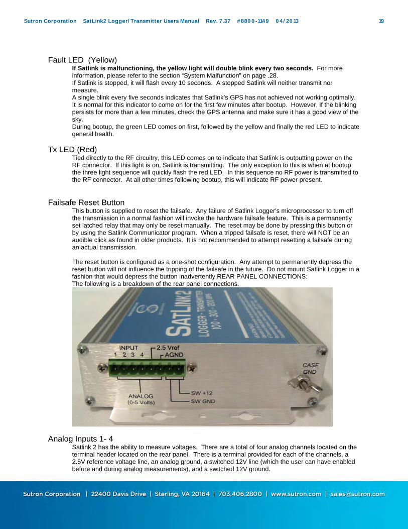
Failsafe Reset Button This button is supplied to reset the failsafe. Any failure of Satlink Logger's microprocessor to turn off the transmission in a normal fashion will invoke the hardware failsafe feature. This is a permanently set latched relay that may only be reset manually. The reset may be done by pressing this button or by using the Satlink Communicator program. When a tripped failsafe is reset, there will NOT be an audible click as found in older products. It is not recommended to attempt resetting a failsafe during an actual transmission. The reset button is configured as a one-shot configuration. Any attempt to permanently depress the reset button will not influence the tripping of the failsafe in the future. Do not mount Satlink Logger in a fashion that would depress the button inadvertently.REAR PANEL CONNECTIONS: The following is a breakdown of the rear panel connections.
Analog Inputs 1- 4 Satlink 2 has the ability to measure voltages. There are a total of four analog channels located on the terminal header located on the rear panel. There is a terminal provided for each of the channels, a 2.5V reference voltage line, an analog ground, a switched 12V line (which the user can have enabled before and during analog measurements), and a switched 12V ground.
Sutron Corporation SatLink2 Logger/Transmitter Users Manual Rev. 7.37 #8800-1149 04/2013 19

Please note that if an equation uses PULSE12, switched 12V will NOT be turned on as a part of measurement warmup. Connect the single ended lines to inputs 1 through 4. The single ended inputs are referenced to analog ground (AGND). Connect differential pairs to Analog Inputs 1 and 2 or 3 and 4. Both sides of the pair must be within 0-5V of analog ground.
2.5 V Reference A 2.5 volt reference is provided for external use. It may only be used as a high impedance source. It should not source more than 10 ma. Do not attempt to use this reference to power a sensor. The 2.5 Vref should be referenced to AGND.
Analog Ground If you are measuring a simple voltage (single ended, 0 to 5 Volts), connect the live wire of the sensor to be measured to any one of the analog channels and the ground wire to the AGND (analog ground) connector. For more details, please see the Analog Measurement section on page 54.
+12V Switched Power A switched +12 volts is provided for sourcing a modest amount of current (< 500 ma max) to sensors that do not need to be powered up all the time. When the A/D readings are made, the switched +12 volts is turned on. The warmup period specified in the setup configuration will turn on the Switched +12 volts prior to the measurement by the amount of seconds specified. Please note that if an equation uses PULSE12, switched 12V will NOT be turned on as a part of measurement warmup.
+12 SWITCHED GROUND Ground pin for Switched +12 output. It is good practice to use separate grounds for analog sensors and Switched power outputs. Never place sensor grounds on the switched 12 ground.
EARTH GROUND LUG Always provide a heavy gauge wire to the earth ground connection. Provide a heavy copper ground stake driven in the earth with a ground strap to this terminal for a good earth return for proper transient protection.
Sutron Corporation SatLink2 Logger/Transmitter Users Manual Rev. 7.37 #8800-1149 04/2013 20

RF POWER INFORMATION:
TRANSMIT POWER The transmit power is factory set for all different satellite types and baud rates at the factory. The following list indicates the power during the carrier for each of the Satellite applications. All applications below reflect the use of a YAGI antenna except for ARGOS/SCD-1.
GOES 100* 7 Watts GOES 300 SL2-G312-1B 7 Watts
GOES 300 G11/12 SL2-G312-V2 2.5 Watts GOES 300 G13+ SL2-G312-V2 1.25 Watts
GOES 1200 SL2-G312-1B 14 Watts GOES 1200 G11/12 SL2-G312-V2 10 Watts GOES 1200 G13+ SL2-G312-V2 5 Watts
INSAT 3.5 Watts METEOSAT 7 Watts
FY-2 7 Watts ARGOS/SCD-1 2.5 Watts
* 100 bps is not supported in SL2-G312-V2 models other than the international channels. Note: Consult factory concerning support for satellite types above. ADJUSTMENT OF POWER The transmit power is set at the factory and is not adjustable by the user. Special cases may permit the adjustment of the transmit power by software, but only under the direction of the factory. RF BOOSTER AMPLIFIERS The use of RF booster amplifiers to increase the transmit power is strictly forbidden by any of the certifying agencies without the pre-approval of the governmental agency or the certification of the Satlink 2 combined with another amplifier. FORWARD AND REFLECTED POWER
NOTE: The forward and reflected power measurements are only rough estimates and should not be used to calibrate the transmitter. The Satlink 2 is equipped with a forward and reflected power measurement capability. This measurement capability is designed to assist the user during the installation and check out of a transmitter. In certain circumstances, the user may even transmit the measured power values appended to the transmission. Measurements include: 1)Forward RF power (Measured during the carrier portion of the message) 2)Reflected RF power (Measured during the carrier portion of the message) The measurement system is not designed to be a replacement to a wattmeter, however, in the absence of a meter on hand will serve as a method to confirm that the antenna system is presenting a proper load to the transmitter. If the user has extra time in the transmission slot, this information may be transmitted as an appended value to the data content.
Sutron Corporation SatLink2 Logger/Transmitter Users Manual Rev. 7.37 #8800-1149 04/2013 21

FORWARD POWER
The forward power is measured via a coupler placed at the RF output along with an RF detector integrated circuit. This generates a voltage that is read via an A/D circuit. The microprocessor calculates the forward RF power based on the mathematical relationship between forward detected voltage and RF power. Measurement Range: 1 to 20 Watts Accuracy: +/- 2 dB (+/- 5 watts at 14 watts) The forward power is measured also as part of the automatic gain control system. As the temperature changes and the power level is adjusted, the net forward power will be relatively accurate due to the stability of the measurement circuit.
REFLECTED POWER
The reflected power is also measured via a coupler placed at the RF output with an RF detector integrated circuit. The microprocessor calculates the forward RF power based on the mathematical relationship between forward detected voltage and RF power. Measurement Range: 1 to 20 Watts Accuracy +/- 2dB (+/- 5 watts at 14 watts) The reflected power measurement is most accurate when the cable length to the antenna is the standard 15 foot cable. However, the measurement will function with other lengths of cables just with slightly more error. In general, a properly matched antenna will generate a returned RF power of 0 watts. Antennas that may have damaged RF cables or missing or broken elements may present reflected power in the 1 to 2 watt range. Typically it is advised to repair the cable or antenna when the reflected power exceeds 1 watt. If for some reason the antenna cable is cut or open circuit, the reflected power will indicate nearly the full forward amount of RF power.
HOW TO MAKE READINGS
The following steps will help in learning how to make measurements: ON SITE CHECKOUT
A station has just been installed or someone is at a site on a visit. Receiving a check of system performance would be beneficial before a person leaves a remote station. The steps are: 1. Make a transmission, either forced or scheduled. 2. Using the Satlink Communicator program, go to the “Diagnostics” Tab an click on the Transmit power button. 3. Select the “Read Power” button and the forward and reflected power will be displayed. This readout represents the last power seen by the detector regardless of the type of transmission made, whether it is a 100/300 or 1200 bps transmission.
OVER THE SATELLITE MONITORING
Sutron Corporation SatLink2 Logger/Transmitter Users Manual Rev. 7.37 #8800-1149 04/2013 22
A provision to append the last transmitted forward and reflected power is built into the system. A check box is provided under the scheduled transmissions tab of the Satlink communicator program for enabling the appended value. NOTE: The transmission will always report the forward and reflected power of the LAST transmission, not the current transmission. SEQUENCE: 1) A transmission is made. The first transmission will report 0.0/0.0 watts for forward and reflected power. 2) On the second transmission, it will append the value for the last transmission of the same scheduled type. 3) On the third transmission, it will append the value of the second transmission of the same scheduled type and so forth.
SPECIAL CASE HANDLING:
If the transmitter is programmed to make scheduled transmissions at 100/300 baud and random transmission at 1200 baud (or the reverse of that), then there might be some confusion as to what power level should be appended to the next message. The problem that arises is that there are different power levels for each transmission type. Satlink 2 will not mix the reporting of the scheduled and random transmission power readings. Therefore, the appended transmit power value will only show the last reading for the last transmitted scheduled transmission. So, for example if the transmitter was to alternate scheduled transmissions at 7 watts with random transmissions at 14 watts, then the only appended value will be the 7 watt value from the last scheduled transmission even though the last physical transmission was 14 watts (for random). This will prevent confusion on the decoding end as to why the transmit power was moving from between 7 and 14 watts.
OBSERVATIONS:
It is generally a good procedure not to append too many characters to the transmission as best practice is to keep the message to the minimum possible length. While it may look like there may be enough room, be certain to leave margins on each side of the message to be transmitted. It is therefore our recommendation to use this forward and reflected power reading only in cases where significant time margins exist in the transmit time slot or for short periods of time to determine the stability or to help resolve problems with the station.
DC INPUT POWER
DC input power is not critical to the transmitter as long as it remains in the range of 10.4 to 15 volts DC. The transmit power is independent of this voltage in this range thereby eliminating varying amount of watts with low battery conditions. It is important to have a well charged battery that is capable of delivering 5 amps without significant sagging under the load during the transmission. The transmission will abort if the voltage drops below the 10.4 volts, the range in which the battery is considered failed. The Satlink 2 will continue running without transmitting well down to the 7 or lower volt range.
Sutron Corporation SatLink2 Logger/Transmitter Users Manual Rev. 7.37 #8800-1149 04/2013 23

Chapter 4 Understanding Satlink Logger
Operations
Sutron Corporation SatLink2 Logger/Transmitter Users Manual Rev. 7.37 #8800-1149 04/2013 24

OVERVIEW
This chapter presents the internal mechanics of the software that runs Satlink Logger. It also describes the principles the user should keep in mind when setting up the logger. All details of how to setup the logger are presented in the chapter titled “Using Satlink Logger Communicator”. The software is composed of two main parts: the self-test bootloader and the main application. The self-test can be invoked at startup (see the Self-Test section of the Maintenance chapter). The main application is responsible for Satlink’s day-to-day operations. It runs under a multi-tasking operating system that allows Satlink to perform measurements and transmissions on independent schedules.
What Satlink Front Panel Lights Indicate There are three LEDs on the front panel of Satlink. When power is applied to Satlink, all three lights will come on in sequence, indicating that Satlink has booted. Afterwards, one of the following scenarios will occur:
Green light blinks once every five seconds – this is the desired state. It means Satlink is up and running, making measurements and transmissions depending on the setup.
Yellow LED blinks every 10 seconds – Satlink has not been setup. It is stopped and will not make transmissions or measurements. To correct this, connect to Satlink via the Communicator program, set it up, and hit Start.
Yellow and green LEDs blink every 5 seconds – Satlink is running but is having GPS trouble. If the yellow light does no go away after two or three minutes, recheck the GPS antenna and make sure it is properly connected and that it has good view of the sky.
Yellow blink every 5 seconds. – Satlink is stopped, and the GPS does not have satellite lock (see the two cases above)
Yellow light blinks twice in a row every two seconds – this is bad. Satlink thinks it is malfunctioning. Either it has bad hardware, is unable to transmit or some other failure. Connect to Satlink with the Communicator program, and the details of the failure will be revealed. Once the problem is fixed, the blink should go away.
Red LED is on solid – Satlink is transmitting (there is power being output through the RF connector).
Green light is on solid – Satlink is getting ready to transmit. You should see the red light come on soon.
Green light blinks twice – Satlink is making a measurement. Green and yellow LEDs are blinking madly – Satlink’s software is being upgraded.
Running and Stopped Satlink Logger has two operating modes: running and stopped. If you are using Satlink Transmitter version 4.11 or older, none of the following apply. A stopped system is Satlink in an idle state, awaiting user input. In this state, Satlink is ready to be configured for operations. Transmissions and measurements can be set up in this mode. Test transmissions and measurements can be initiated by the user to demonstrate that the system is operating properly. A running system is a configured system that is making measurements and transmissions. An operational Satlink is expected to be left in running mode. Most configuration settings may not be changed while the system is running.
Sutron Corporation SatLink2 Logger/Transmitter Users Manual Rev. 7.37 #8800-1149 04/2013 25

Upon power up, Satlink will attempt to resume the state if it had last: if it was running when power was turned off, it will attempt to start running when power is next applied. If Satlink was stopped when power was taken away, it will be stopped when it is next powered. This behavior was introduced with Satlink version 5.04. Satlink’s older than 5.04 had an autostart option – whether it was selected or not determined whether Satlink would go into running or stopped mode upon bootup. The red LED on the front panel will indicate that Satlink is stopped by blinking once every 10 seconds; a running system will flash the LED every 5 seconds. Satlink will refuse to start if it has any invalid settings or if it is in the course of a transmission.
Configuring Satlink Logger When configuring Satlink logger, the user is expected to follow these steps:
1. Set the system to defaults. If this is a brand new unit, the unit should already be in this state. If not, the user can set the system to factory defaults using the Communicator program (Diagnostic tab of the Communicator program).
2. Set up Satlink’s configuration: This involves setting the measurement types and schedules, as well as transmission interval, times, and satellite ID. The details of setup are described in the chapter titled “Using Satlink Logger Communicator”.
3. Each part of the setup should be tested. If sensors are connected, measurements should be tested by forcing a measurement and by examining the results. A transmission should also be forced. Make sure to transmit into a dummy load – not on air. Monitor Satlink’s status to ensure that it reports a successful transmission.
4. Start Satlink, just to ensure that the setup is proper. If the setup is invalid or incomplete, Satlink will notify you of the problem. Otherwise, it will go into running mode.
5. If the user is at the site where Satlink will be left to operate, leave the Satlink running. If not, power down Satlink. If Satlink is running when powered off, it will resume running when power is next applied.
Understanding Transmisssions Each transmission consists of several phases. Scheduled transmissions must occur at designated times. Prior to this designated time is when preparation for the transmission must commence. The first phase of the preparation is GPS satellite acquisition. The GPS needs to be turned on early enough to allow for satellite acquisition, which takes a variable amount of time (the time depends on weather and the position of the GPS satellites). The maximum amount of time given to the GPS is three minutes. Satlink is set up for redundant GPS satellite acquisition: should one acquisition fail, the system will fall back on the previous one and continue with the transmission. In any case, if GPS fails to acquire satellites, Satlink will have the GPS retry several times. Also note that Satlink turns on the GPS every 30 minutes in order to maintain satellite signal. In the unlikely event of repeated GPS failures, try repositioning the GPS antenna. The most likely cause of GPS failures is GPS antenna obstruction (such as snow covering the antenna). The second phase of the preparation is referred to as the frequency discipline. It ensures that Satlink transmits exactly on frequency even under the harshest of temperature conditions. The third phase involves encoding data from sensors connected to Satlink. In this phase Satlink prepares data which has previously been collected. Make sure to set up your measurements
Sutron Corporation SatLink2 Logger/Transmitter Users Manual Rev. 7.37 #8800-1149 04/2013 26
such that they take place prior to transmission (three minutes prior to transmission should be a safe time). This way you ensure that the most current data will be transmitted. The next phase involves preparing data, which has been given to Satlink by another logger (such as Sutron’s 8210 Data Recorder). The last phase has Satlink turn on the RF hardware, which will send the transmission.
Data Buffers Satlink Logger’s data merge capability allows Satlink to handle two kinds of transmission data. External data is data given to Satlink from another device (such as Sutron’s Xpert data logger). Sensor data is data collected by Satlink from sensors directly connected to it. External data has its own buffer. This buffer is large enough to handle the maximum amount of data that can be sent in a single transmission (12 kilobytes). Satlink will automatically empty this buffer after a transmission, unless the Circular Buffer option (Advanced Scheduled Tab of the Communicator program) has been selected, in which case any unsent data gets kept for the next transmission. The user may limit the amount of data that gets sent by using the Window Centering (Scheduled Tab of the Communicator program) option. The buffer will also get emptied when the user starts Satlink, and upon power up. Note: SL2-G312-V2 units certified under V2.0 Certification rules have the following new buffer lengths: 300 bps: 4000 bytes
1200 bps: 16000 bytes
External data should be given to Satlink about 60 seconds prior to transmission. If there is a desire to give the data closer to transmission, Satlink needs to be asked until when data is accepted into the buffer. There exists a command that can be sent to Satlink via the serial port to find out just how close to a transmission the data can be given. If the data is given too late, it is sent in the next transmission. Sensor data gets stored in a buffer that holds the last 32 readings of each of the 16 measurements. This data gets lost upon power up. Both External and Sensor data are available to the user for inspection. Satlink is also able to show the user what a transmission message will look like. Please refer to details on page 77 to find out how to inspect Satlink’s data buffers.
Understanding Measurements Satlink Logger is capable of making multiple measurements each of which has an independent schedule. When more than one measurement is scheduled to occur at the same time, the following will happen:
If all the measurements are different from each other (they require talking to different sensors), they will happen in sequential order, starting with measurement index 1. For example, if measurement 1 is set to talk to an SDI-12 sensor, and measurement 2 is set to talk to a tipping bucket, when it is time to collect data, the SDI-12 measurement will be made, and once it is complete the tipping bucket measurement will be made.
If two measurements use the same reading, then only one reading will be made, and the two measurements will be calculated from the same reading. For example, if there are two tipping bucket measurements scheduled for the same time but with a different slope
Sutron Corporation SatLink2 Logger/Transmitter Users Manual Rev. 7.37 #8800-1149 04/2013 27

and offset, only one reading of the tipping bucket will be made. Another example may have an SDI-12 sensor that returns two parameters in one reading. One measurement would be set to parameter 1, and the other to parameter 2. Assuming both measurements are scheduled to occur at the same time, when time for measurement came, one reading would be made from the SDI-12 sensor, and both measurements would be calculated from that reading.
If the user wanted to set up a station that would log rainfall once an hour and that would have an alarm checking rainfall every five minutes, the following setup would be appropriate: both measurements would be set up to be tipping buckets. One measurement would be set up to an interval of one hour; it would also be set up to log and to be included in scheduled transmissions. The other measurement would not be set up to log; it would be set to an interval of five minutes and it would be set to be included in random transmissions.
SDI Clock Synchronization Certain Sutron SDI-12 sensors (such as the SDR, RLR, and the CF Bubbler) support a command which is used to set the time of the sensor. Satlink takes advantage of that feature, and periodically sets the clock of the sensor, ensuring that the accurate time provided to Satlink by GPS is shared with the sensors. When started, Satlink will send an identify command to all the SDI devices that Satlink has been setup to measure. Any device that responds with SUTRON in the reply will have the read time XDT command issued to it. All devices that correctly reply will have thier time set by Satlink. Satlink will send the set time command to the sensors when Satlink is started and every 24 hours thereafter. The set time command takes the format aXDTYYYY/MM/DD HH:MM:SS!
a is address XDT is the command to set the date and time YYYY is the year MM is the month (01 to 12) DD is the day of the month (01 to 31) HH is the hour (military time 0 to 23) MM is the minutes SS is the seconds
Example set date time command: 0XDT2005/09/01 13:15:00!
System Malfunction As a part of the status, Satlink reports whether the system is malfunctioning. Any of the following symptoms cause Satlink to consider itself 'malfunctioning':
System failed to autostart. Failed last two consecutive transmissions. Failed last two consecutive readings of any single measurement. Failed at least 25% of all transmissions (if the system has made more than a total of 4
transmissions). Battery voltage low. Failsafe tripped.
A malfunctioning Satlink will blink red heartbeat LED every 2 seconds.
Sutron Corporation SatLink2 Logger/Transmitter Users Manual Rev. 7.37 #8800-1149 04/2013 28
Chapter 5 Using Satlink Logger Communicator
Sutron Corporation SatLink2 Logger/Transmitter Users Manual Rev. 7.37 #8800-1149 04/2013 29

OVERVIEW
Satlink Logger's visual interface program, referred to as Satlink Logger Communicator, is a Windows program that gives you the ability to configure a Satlink Logger transmitter. A separate program that runs on Pocket PC platforms (e.g. the HP iPaq) is also available from Sutron. This latter program is referred to as SatComm. You will need either the Satlink Logger Communicator version 3.0 (or above), or SatComm version 1.0, to be able to talk to Satlink Logger (and SatComm version 2.0 or above to speak to Satlink 2). Satlink Communicator will work with Satlink transmitters version 4.11 or older. However, not all of the features will be available (namely measurement and logging) and some controls will be inaccessible. SatComm will work with Satlink loggers version 5.0 and above. The setup consists of information such as the measurement setup, logging setup, the assigned transmission ID, transmission time, and interval. Satlink Logger stores this configuration into permanent memory so that once configured, it will remember the configuration and restore it each time it is powered up. Satlink Logger's visual interface program is not needed if you are using Satlink Logger as just a transmitter and are connected to an advanced data recorder such as Sutron’s Xpert or 8210. These data recorders have built-in programs that can set up a Satlink Logger transmitter. Refer to Appendix A if you are using Satlink Logger with the 8210 or Appendix B if you are using Satlink Logger with the Xpert. However, you should still familiarize yourself with the Satlink Logger Communicator program.
Understanding Satlink Setups and How Communicator Talks to Satlink
A setup is a collection of settings used to configure Satlink. Satlink’s setup is composed of settings such as transmission time and interval, satellite id and measurement type. Using the Communicator program, setups can be saved and loaded to and from files. The Communicator program can also read and write the setup from and to a connected Satlink. It is possible to work on a setup without being connected to Satlink. The user may configure a setup and save it to file. Once Satlink is connected, that and any other saved setup may be sent to Satlink, thereby configuring it. When making changes to the setup in the Communicator program, no communication will take place with Satlink until the user chooses to send setup to Satlink. So, if the user disconnects Satlink before sending the setup to Satlink, Satlink’s setup will not have changed. IT IS NECESSARY THAT THE SETUP BE SENT TO SATLINK BEFORE DISCONNECTING.
Sutron Corporation SatLink2 Logger/Transmitter Users Manual Rev. 7.37 #8800-1149 04/2013 30
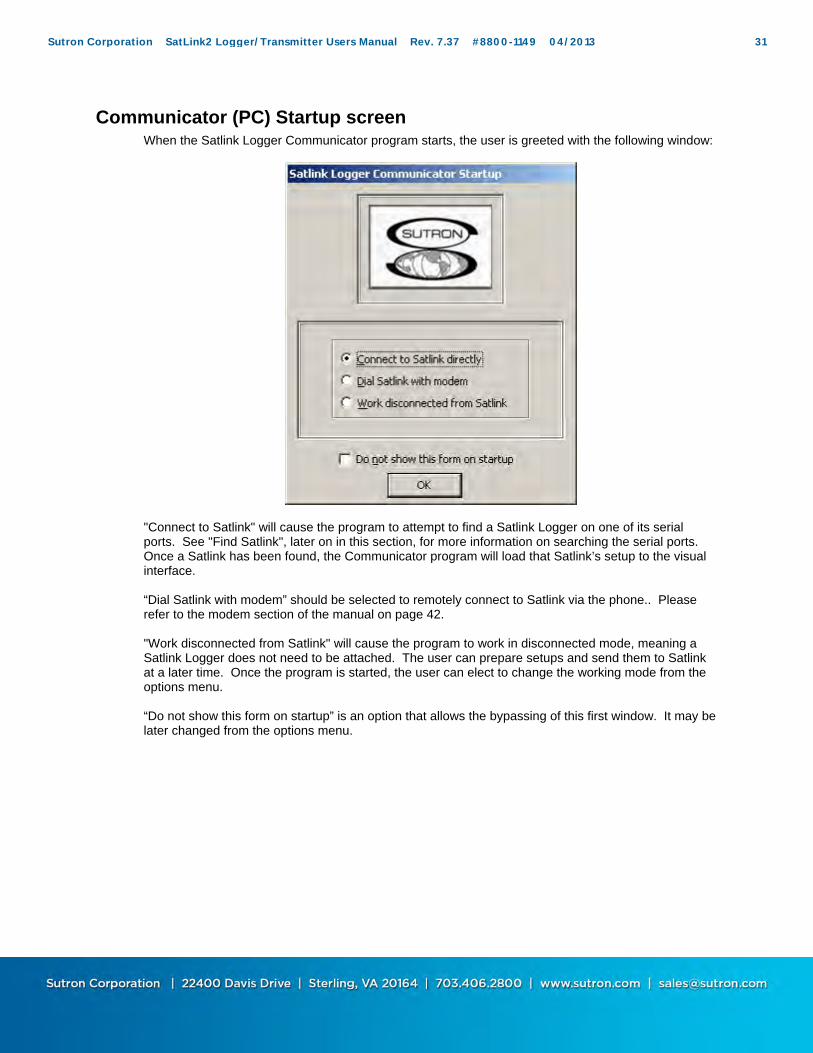
Communicator (PC) Startup screen When the Satlink Logger Communicator program starts, the user is greeted with the following window:
"Connect to Satlink" will cause the program to attempt to find a Satlink Logger on one of its serial ports. See "Find Satlink", later on in this section, for more information on searching the serial ports. Once a Satlink has been found, the Communicator program will load that Satlink’s setup to the visual interface. “Dial Satlink with modem” should be selected to remotely connect to Satlink via the phone.. Please refer to the modem section of the manual on page 42. "Work disconnected from Satlink" will cause the program to work in disconnected mode, meaning a Satlink Logger does not need to be attached. The user can prepare setups and send them to Satlink at a later time. Once the program is started, the user can elect to change the working mode from the options menu. “Do not show this form on startup” is an option that allows the bypassing of this first window. It may be later changed from the options menu.
Sutron Corporation SatLink2 Logger/Transmitter Users Manual Rev. 7.37 #8800-1149 04/2013 31
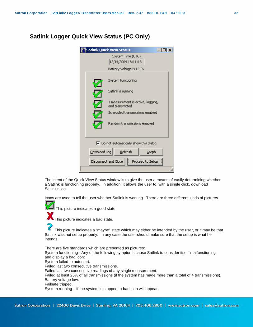
Satlink Logger Quick View Status (PC Only)
The intent of the Quick View Status window is to give the user a means of easily determining whether a Satlink is functioning properly. In addition, it allows the user to, with a single click, download Satlink’s log. Icons are used to tell the user whether Satlink is working. There are three different kinds of pictures
This picture indicates a good state.
This picture indicates a bad state.
This picture indicates a “maybe” state which may either be intended by the user, or it may be that Satlink was not setup properly. In any case the user should make sure that the setup is what he intends. There are five standards which are presented as pictures: System functioning - Any of the following symptoms cause Satlink to consider itself 'malfunctioning' and display a bad icon: System failed to autostart. Failed last two consecutive transmissions. Failed last two consecutive readings of any single measurement. Failed at least 25% of all transmissions (if the system has made more than a total of 4 transmissions). Battery voltage low. Failsafe tripped. System running – if the system is stopped, a bad icon will appear.
Sutron Corporation SatLink2 Logger/Transmitter Users Manual Rev. 7.37 #8800-1149 04/2013 32

Measurements active and logging. If Satlink has at least one measurement active and logging, a good icon will appear. Otherwise, a maybe icon will appear. Scheduled transmissions need to be enabled in order for a good icon to appear; otherwise a maybe icon appears. Random transmissions being enabled will cause a good icon to appear. Hitting the “Download Log” button will download all the data logged since the last download, and save it to a default file name which consists of the station name and the current date. After the download is complete, the user is told what file the log was saved to. The “Graph” button will bring up a graph representing the last 32 readings of each active measurement. For more information please see the graphing section on page 67. The “Refresh” button is used if the user connects to a different Satlink. “Close Communicator”, if pressed, will exit the program without further ado. “Proceed to Setup” will take the user to the rest of the Communicator program. The “Do not show this dialog on startup”, if checked, will not show this dialog when the Communicator is started. Once selected this option can be changed from the Options menu in the main window. The Quick View Status dialog can be displayed from the tools menu, or via a button from the main tab.
The picture above is what a malfunctioning Satlink would report. The Communicator’s main screen looks like this:
Sutron Corporation SatLink2 Logger/Transmitter Users Manual Rev. 7.37 #8800-1149 04/2013 33
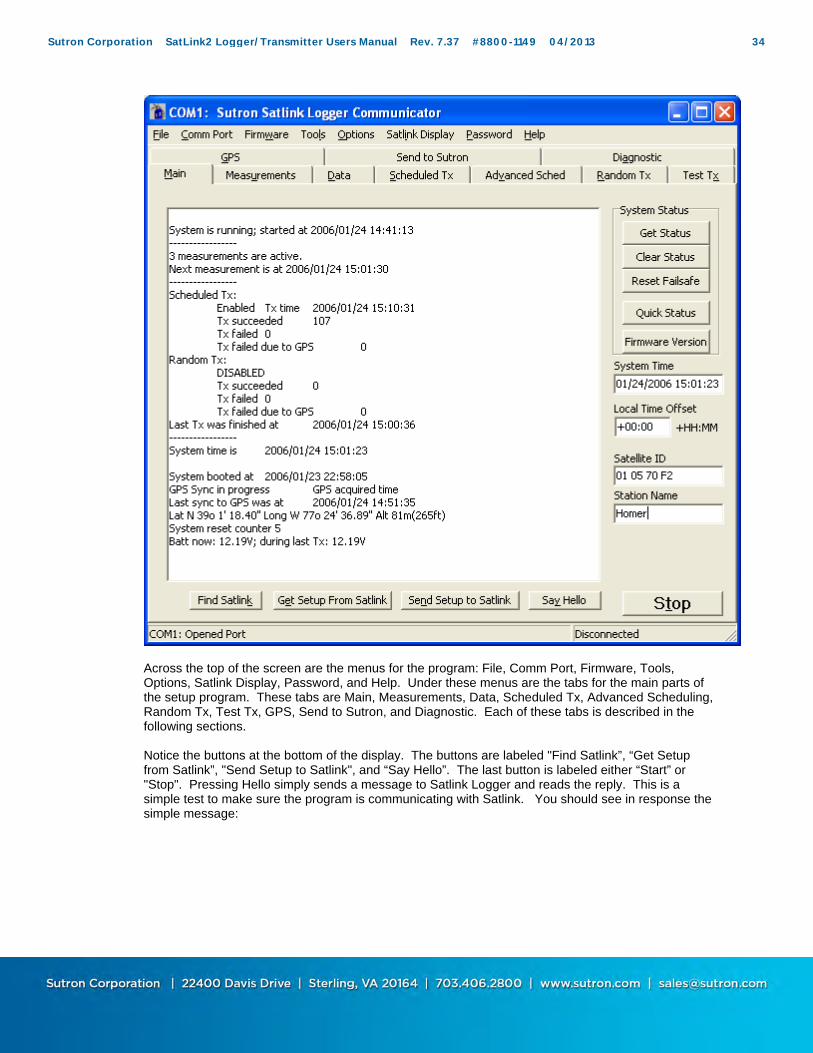
Across the top of the screen are the menus for the program: File, Comm Port, Firmware, Tools, Options, Satlink Display, Password, and Help. Under these menus are the tabs for the main parts of the setup program. These tabs are Main, Measurements, Data, Scheduled Tx, Advanced Scheduling, Random Tx, Test Tx, GPS, Send to Sutron, and Diagnostic. Each of these tabs is described in the following sections. Notice the buttons at the bottom of the display. The buttons are labeled "Find Satlink”, “Get Setup from Satlink”, "Send Setup to Satlink", and “Say Hello”. The last button is labeled either “Start” or "Stop". Pressing Hello simply sends a message to Satlink Logger and reads the reply. This is a simple test to make sure the program is communicating with Satlink. You should see in response the simple message:
Sutron Corporation SatLink2 Logger/Transmitter Users Manual Rev. 7.37 #8800-1149 04/2013 34
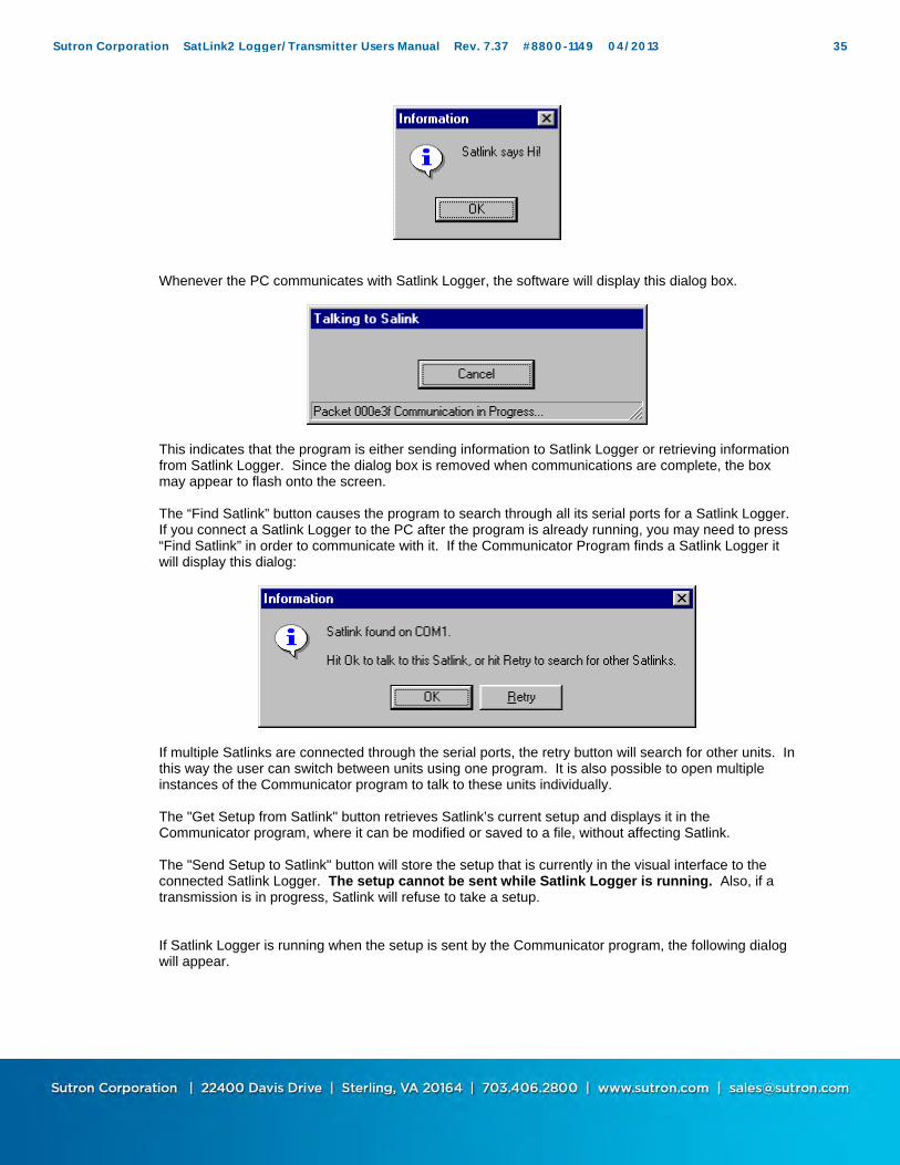
Whenever the PC communicates with Satlink Logger, the software will display this dialog box.
This indicates that the program is either sending information to Satlink Logger or retrieving information from Satlink Logger. Since the dialog box is removed when communications are complete, the box may appear to flash onto the screen. The “Find Satlink” button causes the program to search through all its serial ports for a Satlink Logger. If you connect a Satlink Logger to the PC after the program is already running, you may need to press “Find Satlink” in order to communicate with it. If the Communicator Program finds a Satlink Logger it will display this dialog:
If multiple Satlinks are connected through the serial ports, the retry button will search for other units. In this way the user can switch between units using one program. It is also possible to open multiple instances of the Communicator program to talk to these units individually. The "Get Setup from Satlink" button retrieves Satlink’s current setup and displays it in the Communicator program, where it can be modified or saved to a file, without affecting Satlink. The "Send Setup to Satlink" button will store the setup that is currently in the visual interface to the connected Satlink Logger. The setup cannot be sent while Satlink Logger is running. Also, if a transmission is in progress, Satlink will refuse to take a setup. If Satlink Logger is running when the setup is sent by the Communicator program, the following dialog will appear.
Sutron Corporation SatLink2 Logger/Transmitter Users Manual Rev. 7.37 #8800-1149 04/2013 35

The first choice will leave the system stopped after sending the setup, while the second will start the system again afterwards. The third choice will cancel and not send the setup. The "Start" button is used to start the system. When a start is requested, Satlink Logger will make validation checks of all its settings. If any setting is found to be invalid, Satlink Logger will refuse to start and will notify the user which settings need to be fixed. The system cannot be started while Satlink Logger is transmitting, or during a user initiated transmission. Note that the “Start” button is not always visible in SatComm as it is in Communicator. The Start button appears only the Main page in SatComm. If you are running Satlink transmitter version 4.11 or older, there will be no start stop button. Instead, there will be a “Finalize” button, which, when pressed, will check Satlink’s setup to verify that it is valid. Once the system is running, the following will happen. If scheduled transmissions are enabled, they will happen at the set interval. Random transmissions, if enabled, will react to alarms and make transmissions at the proper interval. Measurements, if made active, will take place periodically according to their interval. A running system will not allow for setup changes nor user initiated scheduled transmissions to be made, so the Communicator Program will prompt the user if it needs to stop the system. The “Stop” button halts any transmissions or measurements on a schedule. While the system is stopped, the user can send the setup from the visual interface to Satlink. If the system is halted after a critical stage in a transmission is reached, the transmission will go through regardless of the system being stopped. This critical stage is a little while before the actual transmission is set to occur.
For more information refer to the section titled “Running and Stopped” in Chapter 4.
Communicator (PC) Menus Communicator’s menu options are “File”, “Comm Port”, “Firmware”, "Tools", “Options”, “Satlink Display”, “Password”, and “Help”. The “File” menu offers several options . “New”, “Open”, “Save”, and “Save as” all refer to the setup. Select “New” to put all the settings to their default value. “Open” will open a previously saved setup. “Save” and “Save As” allow the user to store the setup in a file. None of these options will cause the Communicator to talk to Satlink. The “Export” option allows the user to save Satlink’s status and/or setup in easy to read, ASCII format. The setup and/or status can be saved to file, copied to the clipboard, or sent to the printer. Depending on what tab is selected, this option captures either the contents of the Main tab’s status window, the Data tab’s data window, the GPS tab’s status window, or the Debug output window.
Sutron Corporation SatLink2 Logger/Transmitter Users Manual Rev. 7.37 #8800-1149 04/2013 36

“Setup Printer” allows the user to configure which printer to use for the “Export Setup” and “Export Status” options. The “Comm Port” menu will allow the user to select, to open, and to close the communications port. Choosing the “Configure” menu will allow the user to choose what comm. port to use to connect to Satlink. The options listed include all ports that Communicator finds on the PC that are not currently in use. If you require a port that is not listed, type it in. For example, to use port 52, type “COM52” into the drop down menu. The “Search Ports for Satlink” menu item has the same effect as hitting the “Find Satlink” button: it searches all the ports on the PC and attempts to contact Satlink Logger through them. Selecting “Modem” from the menu will bring up a window which can be used to dial to a remote Satlink using a phone modem. More details on using a modem to connect to Satlink can be found on page The “Firmware” menu allows the user to check the current version of the main application code running in Satlink Logger. Upgrading the firmware can also be accomplished by using this menu. To upgrade the firmware, the user will need a “.upg” file provided by Sutron. Please refer to the section entitled ”Upgrading Satlink Firmware” on page 95. The "Tools" menu contains the commands "Get Setup from Satlink" and "Send Setup to Satlink". These options either load the setup to a Satlink or from the Satlink. They work the same as the buttons at the bottom of every tab. After making changes to the setup, make sure to send setup to Satlink. Selecting “Quick Status” from the menu shows the Quick View window that reports Satlink’s status. Option “Export Log” allows the user to download Satlink’s log (more information in the Data Tab section). “Graph Data” will bring up a graph of user selected data gathered by Satlink. The “Options” menu allows the user to enable/disable the auto-updating feature of the program. Auto updating is responsible for periodically updating the “System Time” field, the status window on the Main tab, and the status window on the GPS tab. If you find that the auto-updating makes it hard to read the status, disable it using this feature. The option labeled “Debug Info in Separate Window” allowed through this menu has to do with the displaying of debug information and is explained later in this document, in the Diagnostic section. If "Work Connected" is checked, Satlink Logger will refresh the data on the Main, Data, and GPS pages every time they are accessed. Disabling this will prevent the Communicator Program from trying to talk to the Satlink Logger. If you wish to manipulate setups without talking to Satlink, deselect the “Work Connected”. “Satlink Display” offers several options for configuring Sutron’s Satlink Display product. A Satlink Display is an optional hardware accessory to Satlink that incorporates an LCD display used to view and setup Satlink. The Display also facilitates modem operation and may even include a built in modem. “Password” offers a means to manage Satlink’s password protection. Please visit the password section on page 37 for details. The “Help” button allows the user to find out the current version of the Communicator Program that is running, and it also provides a link to Sutron’s website.
Password Protection Introduced in version 6.12, password protection allows the user to deny access to those without a password. By going to the password menu and selecting “Settings”, the following dialog shows up:
Sutron Corporation SatLink2 Logger/Transmitter Users Manual Rev. 7.37 #8800-1149 04/2013 37
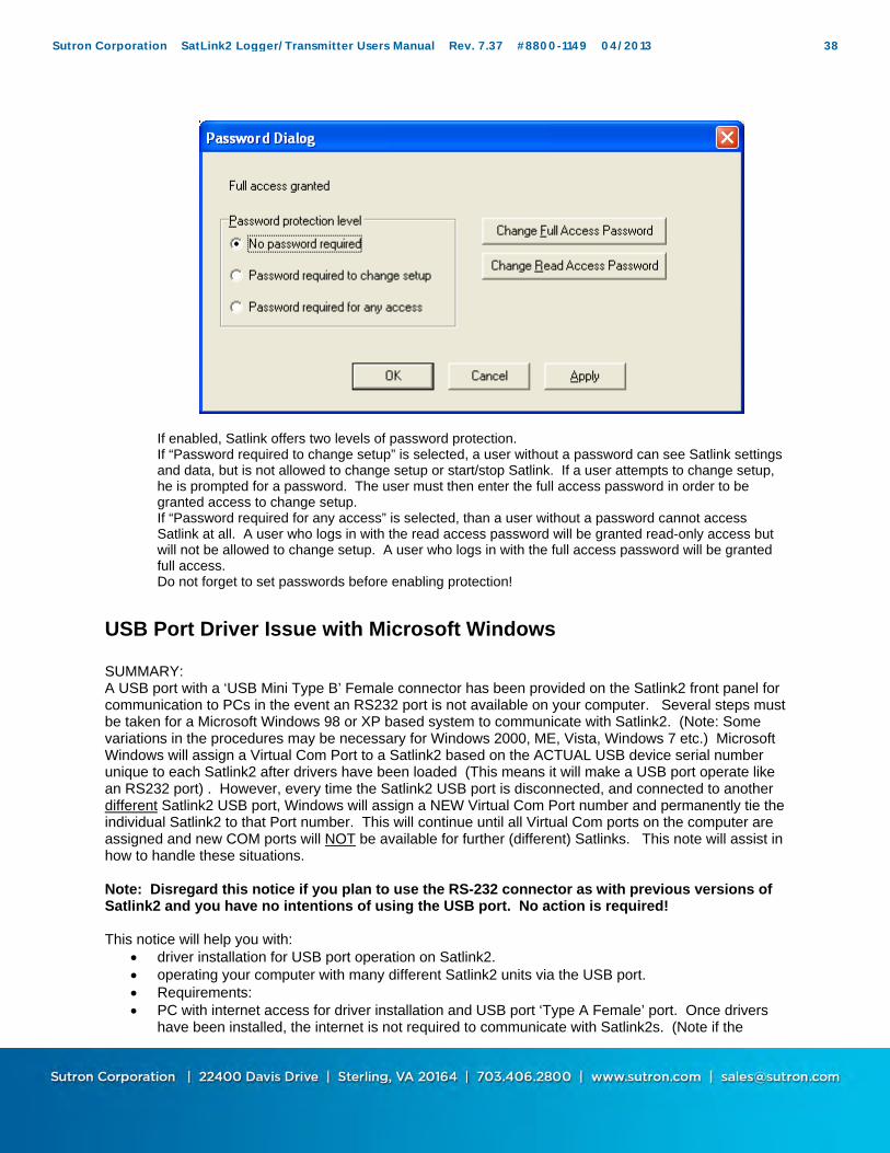
If enabled, Satlink offers two levels of password protection. If “Password required to change setup” is selected, a user without a password can see Satlink settings and data, but is not allowed to change setup or start/stop Satlink. If a user attempts to change setup, he is prompted for a password. The user must then enter the full access password in order to be granted access to change setup. If “Password required for any access” is selected, than a user without a password cannot access Satlink at all. A user who logs in with the read access password will be granted read-only access but will not be allowed to change setup. A user who logs in with the full access password will be granted full access. Do not forget to set passwords before enabling protection!
USB Port Driver Issue with Microsoft Windows
SUMMARY: A USB port with a ‘USB Mini Type B’ Female connector has been provided on the Satlink2 front panel for communication to PCs in the event an RS232 port is not available on your computer. Several steps must be taken for a Microsoft Windows 98 or XP based system to communicate with Satlink2. (Note: Some variations in the procedures may be necessary for Windows 2000, ME, Vista, Windows 7 etc.) Microsoft Windows will assign a Virtual Com Port to a Satlink2 based on the ACTUAL USB device serial number unique to each Satlink2 after drivers have been loaded (This means it will make a USB port operate like an RS232 port) . However, every time the Satlink2 USB port is disconnected, and connected to another different Satlink2 USB port, Windows will assign a NEW Virtual Com Port number and permanently tie the individual Satlink2 to that Port number. This will continue until all Virtual Com ports on the computer are assigned and new COM ports will NOT be available for further (different) Satlinks. This note will assist in how to handle these situations. Note: Disregard this notice if you plan to use the RS-232 connector as with previous versions of Satlink2 and you have no intentions of using the USB port. No action is required!
This notice will help you with:
driver installation for USB port operation on Satlink2. operating your computer with many different Satlink2 units via the USB port. Requirements: PC with internet access for driver installation and USB port ‘Type A Female’ port. Once drivers
have been installed, the internet is not required to communicate with Satlink2s. (Note if the
Sutron Corporation SatLink2 Logger/Transmitter Users Manual Rev. 7.37 #8800-1149 04/2013 38

internet is not available, the drivers may be loaded on to a media that the computer may read from, such as memory stick, floppy drive, etc.)
USB transition cable to connect PC to Satlink2. ‘USB Male Type A’ to ‘USB Male Type ‘Mini’ B’ transition cable is necessary.
INSTRUCTIONS FOR DRIVER INSTALLATION FOR COMPUTER OPERATION WITH MAXIMUM OF SEVERAL SATLINK2s.
With Satlink2 powered up, connect the Satlink2 to the PC or laptop via the USB transition cable. Windows 98 and XP will automatically run a wizard to help locate the ‘FTDI’ drivers from
Microsoft Update website. Allow time for the driver to be located and installed. Follow the instructions if rebooting is necessary. If the drivers are unable to be located, they may be downloaded and placed on the computer manually. (see below for driver locations)
Once the drivers are installed, install the latest copy of Sutron Satlink Communicator. Older versions of Satlink Communicator may not recognize Com Port assignments over 9.
Launch and run Satlink Communicator and the operation will be the same as previously over the RS232 port with Satlink2. Select “Find Satlink”. The drivers should remain on the computer for any future use where the internet is not available.
INSTRUCTIONS FOR SYSTEM VARIABLE MODIFICATIONS PRIOR TO DRIVER INSTALLATION FOR COMPUTERS OPERATING WITH LARGE NUMBER OF SATLINK2s. Before the USB Virtual Com Port drivers are to be installed, Microsoft Windows must be instructed to IGNORE hardware serial numbers. This will allow a computer to be connected to an infinite number of Satlink2s (not at the same time of course!) without permanently assigning unique Com Ports for each device. This must be done by editing the Registry on the computer. If you are not comfortable doing this, have your IT department assist you . So for example if you connect to many different Satlink2s over time, they would always come up with the same Com Port number every time. Follow Step 1 below to correct this issue. Follow step 2 below when you have run out of Virtual Com Port assignments and the computer will not connect to Satlink2. This second and frustrating problem is that windows will hide the Virtual Com Port assignments (called Phantom devices) from the list presented in the Windows Device Manager when the physical devices are removed from the USB cable. So in the event many different Satlinks were connected without the Registry being edited as shown above, the Virtual Com Ports will be assigned and permanently dedicated even though they are not in use. You may enable hidden ports by right clicking ‘My Computer’ and selecting properties. Select the ‘Hardware’ tab and then select the ‘Device Manager’ button. On the Menu bar, select ‘View’ and then check “Show Hidden Devices”. However this will not show DETACHED but STILL ASSIGNED Virtual Com Ports that were assigned when Satlinks were connected in the past. In order to see ALL the assigned Virtual Com Ports, follow the steps in #2 below. This step is not really necessary if you edit the registry first. If, however, you have run out of Virtual Com Port assignments, then you need to do this to SEE the previous assignments in order that you may then right click them and delete them. Sutron recommends this step in all cases as it is always valuable to see what devices are defined in the Hardware Manager.
Edit Registry.
From the Start menu, select the Run Icon and type “regedit”. This will open up a directory like structure. Locate the following directory: HKEY_LOCAL_MACHINE\SYSTEM\CurrentControlSet\Control\UsbFlags Do not go into any subdirectories at the ‘UsbFlags’ level. Right click ‘UsbFlags’ and select ‘New’ and select ‘Binary Value’. Where “New Value #1” is displayed, change the name to “IgnoreHWSerNum04036001” and press enter. Then select the item just renamed (double click)
Sutron Corporation SatLink2 Logger/Transmitter Users Manual Rev. 7.37 #8800-1149 04/2013 39
and ‘0000’ will be displayed. Enter ‘01’ just to the right of the ‘0000’ and press enter. Exit the Registry using the Exit on the menu bar.
Enable Windows to Display Hidden (Phantom) Virtual Com Port Assignments.
To display phantom devices in Device Manager, a new system variable is required. (Note that this applies to Windows XP and may vary for other operating systems) Once again, right click the ‘My Computer’ icon and select ‘properties’. Select the ‘Advanced’ tab. At the bottom, select the ‘Environment Variables’ tab (NOT THE USER VARIABLES SECTION). At the bottom of the window under ‘System Variables’, select New. Under Variable name enter, “DevMgr_Show_NonPresent_Devices”. In the ‘Variable Value’ field, enter “1” and select ‘OK’. Close the tab. Now when you open Device Manager, you will see all the Virtual Com Ports that have been assigned. Finally, unused devices may be deleted now that the unused ports are visible. Now load the Virtual Com Port drivers as shown above in INSTRUCTIONS FOR DRIVER INSTALLATION FOR COMPUTER OPERATION WITH MAXIMUM OF SEVERAL SATLINK2s. Driver Files for the Virtual Com Port operation may be found at: 1) Go to the following Website: http://www.ftdichip.com/Drivers/VCP.htm Select the operating system (example Windows XP) and select the device called “FT232R”. In this example, download the file that has the software revision number: ‘2.04.16’. Copy this file to your computer. 2) Alternately go to the Sutron Download Software page and locate the files under the Satlink2 section.
SatComm (PocketPC) Specifics SatComm operates with Satlinks that are version 5 or higher. Before installing SatComm, if a previous version is already installed, uninstall it.
NOTE: SatComm will not support the newer SL2-G312-V2 Satlinks.
SatComm Startup and Operation When SatComm is first run, the software attempts to communicate with Satlink to retrieve the current status and display it in the Main view. If SatComm and Satlink are communicating, you should see the current system status, station name and ID on the display. If you are not connected to Satlink, or if there was a problem with the communications, the message “Communications with Satlink failed, Please check connections”, will appear in the Status box. Connected or not, you will be able create or edit the Satlink setup stored locally on the handheld using the SatComm program. After SatComm is started, it’s setup represents whatever setup file was last used. This, of course, may not represent the setup of the connected Satlink. To synchronize the setup to the connected Satlink, select “Tools – Get from Satlink.” As changes are made to the setup, these changes are not actually loaded into the connected Satlink until the setup is sent to Satlink using “Tools – Send to
Sutron Corporation SatLink2 Logger/Transmitter Users Manual Rev. 7.37 #8800-1149 04/2013 40

Satlink”. Hence, the usual procedure for using SatComm with a Satlink is to first get the setup, make desired changes, and then send the modified setup to Satlink. A possible exception to the procedure above would be when you need to load a setup configured off-line into one or more Satlinks. In this case, you would just connect and send the setup. Note that when you want to copy setup files to a pocket PC running SatComm, the correct directory destination is “My Documents\SatComm”. Satlink setup files have the extension “.sls”.
SatComm Menus SatComm’s menu options are “File”, “View”, “Tools”, and “Options”. The “File” menu offers “New”, “Open…”, “Save As…”, and “Exit”. Select “New” to set all settings on the hanheld device to their default value. “Open” will open a previously saved setup. “Save As” allows the user to store the setup in a file. Note that there is no “Save” option. This is because SatComm, like most Pocket PC applications, saves all settings as they are changed. Since changes are saved automatically, use the “New” command with care since all settings of the current file will be reset, with no chance to undo. “Exit” is used to terminate the SatComm program. Pressing the “X” button in the upper right of the display only hides the SatComm appplication; it does not close the application (freeing memory and the comm port). The only way to stop and close the program is to use the “File”, “Exit” menu item. The “View” menu is used to select the page to view. A check-mark appears by the page currently selected. The supported views are: Main, Measurements(1), Measurements(2), Data, Scheduled Tx, Adv Sched Tx, Random Tx, GPS and Test. These views provide roughly the same functions available on the tabs of the PC Communicator program. The "Tools" menu contains the commands "Send to Satlink" and “Get from Satlink”. These commands either send the setup to a Satlink or get it from a Satlink. Since changes are saved automatically, use the “Get from Satlink” command with care since all settings of the current file will be set to the values from Satlink, with no chance to undo. The “Reset to factory defaults” command on the “Tools” menu commands the Satlink to set its settings to the pre-programmed factory defaults. This command does not set the local file settings to the same as those in Satlink. If this is desired, follow the command with a “Get from Satlink” command. The “Tools” menu command “Get Satlink Version” displays a dialog containing the version of the firmware as reported by Satlink. The “Upgrade firmware…” command allows you to select an upgrade file to upgrade Satlink firmware. If you are connected to a Satlink Display, you can use the “Tools” menu command “Get Display Version” to display a dialog containing the version of the display firmware. The “Clear Display password” command allows you to clear the password currently set in the Display. The “Upgrade Display…” command allows you to select an upgrade file to upgrade the Display firmware. The “Options” menu command “Satlink Connected” allows you to select whether you are connected to a Satlink. If "Satlink Connected" is checked, SatComm will refresh the data on the Main, Data, and GPS pages every time they are accessed. Unchecking "Satlink Connected" will prevent SatComm from trying to talk to Satlink. If you wish to manipulate setups without talking to Satlink, deselect “Satlink Connected”. This happens automatically when a communication failure occurs. The “Bluetooth Mode” command on the “Options” menu allows you to specify whether SatComm is using Bluetooth to talk to Satlink. When communicating to Satlink via bluetooth, the baud rate cannot increase from 9600 during firmware upgrades and/or log downloads. The “Set Comm Port…” command on the “Options” menu allows you to set which com port to use to talk to Satlink.
Sutron Corporation SatLink2 Logger/Transmitter Users Manual Rev. 7.37 #8800-1149 04/2013 41

Using a Modem With the introduction of Satlink software version 6.07, Satlink has been able to talk via Modem. Satlink can be contacted by dialing though the Communicator program. Satlink cannot dial out on its own. In order for modem communication to work, Satlink must be connected to a modem which is setup to auto-answer. To setup a modem to auto-answer, issue it the ATS0=1 command. In addition, the PC on which the Communicator is run needs to have a modem. The following window can be shown via the Comm Port, Modem menu. If your modem is properly configured, simply enter the phone number that Satlink is connected to and hit the “Dial” button. Be patient while Communicator establishes connection. Status updates will appear in the status bar. Once a connection is established, the Modem window will close and the Main window will appear. Changing setups, downloading logs, and just about everything that can be done via direct connection can be done via modem connection. Upgrading via modem is not recommended as poor line quality may result in a botched upgrade and a dysfunctional Satlink. Once the connection is complete, select “Hang up” from the Comm Port menu, the Modem window, or close Communicator. The advanced options of the Modem window can be used to configure a modem. Click the “Advanced” button to have all the options appear. The option to “Set modem to factory defaults” should be checked unless a special configuration has been placed into the modem. The “Modem Initialization” entry can be used to send a command to the modem prior to every connection. If direct access to the modem is desired, type an AT command in the “Data to be sent” entry and click the “Send” button. The modem’s response will appear. Please note that there exists a separate manual for a Satlink with a display that has more details on modem communications. The manual can be found at www.sutron.com
Sutron Corporation SatLink2 Logger/Transmitter Users Manual Rev. 7.37 #8800-1149 04/2013 42

Using Bluetooth Many Pocket PC handheld computers have Bluetooth wireless communication capability built-in. With the addition of a Bluetooth serial adapter (e.g., the Socket-brand Cordless Serial Adapter), this allows SatComm to communicate with Satlink wirelessly. Some bluetooth serial adapters look to pin 9 to provide a 12V power source. Satlink 2 provides this power. Since baud rate cannot be renegotiated during operation, the “Bluetooth Mode” option under the Options menu must be selected. Typically, the serial adapter must be configured for use as a serial-line replacement. This means connecting the adapter to a host PC and running a program to configure various settings: 9600 baud, a device name of your choosing, device roll = acceptor, connectable = on, discoverable = on, notifications = off, and no security. On the Pocket PC handheld, you typically need to turn bluetooth on before you start SatComm. After turning bluetooth on, start SatComm and then use the ‘Set Comm Port” option under the “Options” menu to set the com port to the one associated with bluetooth on your particular device. The bluetooth port number varies across Pocket PC devices, but is typically found by looking in the “Bluetooth Settings – Serial Port” menu. Use the port identified as the “outbound port”. When the correct port is first used, the Pocket PC Bluetooth Manager will open and prompt you to select the bluetooth device you want to talk to. Select the serial adapter you configured for use with Satlink.
Using SatComm with Optional Serial Cards It is often desireable to use one of several optional serial cards with a Pocket PC device in order to leave the main device connector free, or when the main connector does not readily offer a com port. For example, many Compact Flash serial I/O cards exist that turn a Compact Flash slot into an RS-232 com port. Typically, these devices require that a device driver be installed before use. However, once this driver is installed, it is a simple matter of selecting the correct com port from SatComm’s “Options” menu to use one of these cards to communicate with Satlink.
Sutron Corporation SatLink2 Logger/Transmitter Users Manual Rev. 7.37 #8800-1149 04/2013 43

MAIN
The Communicator Main tab and SatComm Main page display system status and information about the transmitter. Images of the tabs are shown below.
The right side of the Communicator window shows the System Date and Time, Satellite ID, and Station Name. The name is only used as an aid to help identify the station. The Satellite ID is the identifier that is transmitted through the satellite to identify each message sent. The field labeled “Local Time Offset” (“LTO” in SatComm) can be used to have Satlink use local time instead of UTC. Enter the offset from UTC in hours and minutes to have Satlink use local time. Leave the setting at zero to have Satlink use UTC. E.g. to have Satlink run on US Eastern Standard Time, enter -05:00, indicating that EST is 5 hours behind UTC.
Sutron Corporation SatLink2 Logger/Transmitter Users Manual Rev. 7.37 #8800-1149 04/2013 44

Get Status/Refresh The “Get Status” button (“Refresh” in SatComm), retrieves from Satlink Logger important information on how the unit has been operating. The status includes information on measurements, scheduled transmissions, random transmissions, general system information and GPS information. It is important to check the status information for errors. Look for failed transmissions, failsafe problems or system errors. Some errors can be caused by improper setup. If you suspect Satlink Logger is set up properly and not operating, contact Sutron customer service for assistance. All the statuses and errors are described in the chapter titled “Maintenance and Troubleshooting”. If the "Enable Auto Update" feature in the options menu is checked, the status will be updated every five seconds, and the clock will be updated once a second. All the times for Satlink Logger are in the format of YYYY/MM/DD HH:MM:SS and are based on UTC (Universal Coordinated Time). YYYY means four digits that indicate the year. If the user has entered a Local Time Offset, then Satlink keeps local time. Otherwise, Satlink runs on UTC time.
Clear Status The “Clear Status” button (“Clear” in SatComm) sends a command to Satlink Logger to clear its status. This will clear its transmission counters and other useful information.
Reset Failsafe Satlink Logger maintains an independent failsafe circuit designed to prevent transmissions in a malfunctioning unit. For example, if Satlink Logger were to leave the transmitter on for more than the allowable time, the failsafe would trip. It would also trip the failsafe if it tried to make two transmissions without enough time in between them. Sutron has designed the system so that the failsafe will not trip under normal operating conditions or under faulty setup conditions. The only time the failsafe will trip is when the unit has malfunctioned or under certain low battery situations. The failsafe is a redundant system independent of the main application both in hardware and in software. The “Reset Failsafe” button (“Reset FS” in SatComm) can be used to reset the failsafe if it is tripped. Another way to reset the failsafe is to press the failsafe reset button on the side of Satlink Logger. Before resetting the failsafe, determine if the reset was due to low battery conditions and correct the
Sutron Corporation SatLink2 Logger/Transmitter Users Manual Rev. 7.37 #8800-1149 04/2013 45
condition. If the failsafe tripped for any other reason, you should contact Sutron customer service for assistance.
Quick Status This button brings up the Quick View Status dialog which is described in its own section.
Firmware Version
The firmware version button displays the version of the software running in Satlink Logger. From time to time, Sutron will release a new version of the software. See the Menu section of this manual for instructions on how to update the software in Satlink Logger. You can tell what version is running in your unit using this button. Software version of Satlink Logger, Satlink bootloader, GPS module and the PIC are displayed with this feature.
Sutron Corporation SatLink2 Logger/Transmitter Users Manual Rev. 7.37 #8800-1149 04/2013 46

MEASUREMENTS
The Communicator’s “Measurements” tab and SatComm’s “Measurements (1)” and “Measurements (2)” pages appear below. These allow the user to configure measurements, set the tipping bucket count, and output SDI commands on the SDI bus.
Sutron Corporation SatLink2 Logger/Transmitter Users Manual Rev. 7.37 #8800-1149 04/2013 47

General Measurement Settings The user can define up to 16 measurements. The “Settings” portion of the Measurements tab on the Communicator, and the “Measurements (1)” page of SatComm, are used to do this. The “Index” box selects which of the 16 measurement's settings to display. These boxes also contain the label of the measurement, and shows whether the measurement is active, indicated by an asterisk prior to the index number. Measurements are made only when the unit is running, i.e., only when the unit has been started.
Label “Label” is an ASCII string used to name a measurement. This string can be up to 7 characters in length and up to 6 characters if measurement is used for MIN/MAX operations. The label is stored with the data in the log so that data can be correlated with the measurement from which it came. This label is also used in a SHEF format transmission to label the data. Refer to http://noaasis.noaa.gov/DCS/htmfiles/schefcodes.html for a list of the SHEF codes published by NESDIS. While you are not required to use the SHEF codes to label your data, using the codes may simplify the overall handling of the data. For ARGOS transmissions, this field has special meaning. Please refer to the Appendix L: ARGOS on page 160 for details.
Active When the “Active” box is checked, the measurement will be processed when the unit is running. When “Active” is not checked, no measurement will be made. In addition, the user will not be allowed to change measurement properties until the “Active” box is checked.
WARNING: Do NOT use function names for labels. When using Equations, certain function names are reserved for example SIN, COS, TAN, ARCTAN etc. The use of these function names as labels will cause undesired operation when the equations are executed.
Sutron Corporation SatLink2 Logger/Transmitter Users Manual Rev. 7.37 #8800-1149 04/2013 48

Send to Log “Send to Log” ( “Log” in SatComm) is used to indicate whether measurement data should be logged. When checked, measurement data is logged. Note that “Slope” and “Offset” are applied before logging the data.
Right Digits The value specified in “Right Digits” determines the precision to be used when displaying and transmitting measurement values. This value is an integer ranging from 0 to 7. Note that logged values are unaffected by this setting.
Schedule: Time and Interval The “Time” and “Interval” fields are used to define when and how often the measurement is to occur. Each is expressed in a string having the format HH:MM:SS (hours, minutes, seconds). “Time” indicates the time relative to the 24-hour clock when the measurement should begin. “Interval” specifies how often the measurement is to occur. For example, if “Time” is set to 00:05:00 and “Interval” is set to 00:10:00, then the measurement will occur every 10 minutes relative to a starting time of 00:05:00 (i.e., 00:05:00, 00:15:00, 00:25:00, … 12:55:00). Minimum interval. How fast Satlink can sample depends on the measurement types. SDI-12 can be sampled every two seconds or as fast as the sensor will allow, whichever is longer. Analog measurements take either one or four seconds, depending on the measurement type. Tipping bucket and manual entry measurements can be done once a second. If Satlink is programmed to have a shorter interval than what is specified above, it may miss measurements and log errors ("missed" or "starting late" errors). In addition, Satlink can never sample any faster than the longest response time sensor (even for concurrent sdi-12 ("C") measurements). Note: the Satlink will not start new measurements until all measurements on an interval have completed. For example, if there are sensors configured to measure at 10:00:00 that take 2 minutes to complete and there are sensors scheduled to measure at 10:01:00, the sensors scheduled for 10:01:00 would not start until 10:02:00. A note on the measurement interval: if there is more than one measurement enabled, the sampling times are cumulative. For example: 1) If one 0 to 5 Volts measurement and one SDI-12 measurement are setup, each of those measurements can only be made once every three seconds (one second for the analog and two seconds for the SDI). This assumes the SDI-12 sensor will have data in two seconds or less. 2) If one 0 to 5 Volts, one SDI-12 with "C" command that takes nine seconds and two SDI-12 with "C" command that takes five seconds, the minimum interval would be ten seconds (all SDI-12 sensors can be measured in nine seconds concurrently and one second for the analog sensor).
Relative to Transmission When “Relative to Tx” ( “Rel Tx” in SatComm) is checked, the measurements “Time” is taken to mean “prior to the next transmission”. For example, if measurement time equals 00:05:00, and measurement interval equals 00:15:00, and scheduled transmissions are set to go at the top of the hour, then the measurement will occur every fifteen minutes relative to a starting time of 00:55:00 (i.e., 00:10:00, 00:25:00, 00:40:00, 00:55:00, etc.). Note that the measurement will still occur at its interval. Note that in order to transmit the most recent data, measurements need to be set up to occur a few minutes before transmissions.
Averaging The “Sampling Interval” and “Averaging Time” fields are used only if the user is interested in averaging measurements. “Sampling Interval” dictates how often to collect data, while “Averaging Time” controls how long to collect data for. “Sampling Interval” is an interval, “Averaging Time” a duration.
Sutron Corporation SatLink2 Logger/Transmitter Users Manual Rev. 7.37 #8800-1149 04/2013 49

If “Sampling Interval” and “Averaging Time” are set to non-zero values, sampling is considered enabled. In that case, Satlink will make a sensor reading every “Sampling Interval” time. Once every “Averaging Time”, Satlink will add up all the sensor readings and divide them by number of readings. This result will be the measurement that will be logged and transmitted. “Averaging Time” was introduced in version 6.30. Prior to this version, the duration of the sample collection (what is now referred to as “Averaging Time”) was equal to “Interval”, meaning that Satlink would always be collecting data every “Sampling Interval”. Satlink can only sample so fast; see the previous section describing the Measurement Interval for Satlink sampling limits. Setup with an “Averaging Time” of 00:01:00 (one minute) and a “Sampling Interval” of 00:00:10 (10 seconds), Satlink will make six readings at the following times:
12:00:00
12:00:10
12:00:20
12:00:30
12:00:40
12:00:50
Why is data not collected at 13:00:00? Because the setup demands that six samples be collected (sampling every 10 seconds for one minute adds up to six samples, not seven). Additionally, if the 13:00:00 extra sample were to be used in two computations (the one that starts at 12:00:00 and the one that starts at 13:00:00), it would skew the average. Please note that the timestamp of the data in the example about will be 12:00:50. If it is important that data be time-stamped at the top of the hour (13:00:00), please set the “Time” field to 00:00:10. That way the first sample will be collected at 12:00:10 and the last sample at 13:00:00. E.g. If one were interested in collecting data once a minute for five minutes at the top of every hour, one would set the “Interval” to 01:00:00, the “Averaging Time” to 00:05:00, and the “Sampling Interval” to 00:01:00. The final data would be the average of 5 samples, and would have the timestamp of 00:04:00. To get a timestamp of 00:05:00, set the “Time” to 00:01:00. Please note that forced measurements will be made of a single sample, even if averaging is enabled.
MinMax
MinMax stands for minimum and maximum. The purpose of this setting is to allow Satlink to measure the minimum (the smallest) and maximum (the largest) sensor reading. This feature was introduced with Satlink version 6.11. When MinMax is enabled, every sampling interval, Satlink will make the measurement. The reading will be compared to the current minimum and maximum. If the reading is less than the current minimum (or greater than the current maximum), it will be remembered as the current minimum (or maximum). In addition, the time of the reading will also be remembered. Once the measurement interval is complete, Satlink will log the minimum, time of minimum, maximum and time of maximum. In addition, these four readings will be remembered for use in transmissions. In order to function properly, the sampling interval needs to be non-zero and less than the measurement interval.
Sutron Corporation SatLink2 Logger/Transmitter Users Manual Rev. 7.37 #8800-1149 04/2013 50

Note that times of minimum and maximum are rounded up to the nearest minute. With a measurement interval of 01:00:00 (one hour), and a sampling interval of 00:20:00 (20 minutes), Satlink will make three readings and record the minimum and the maximum.
Time Reading Remark 12:00:00 10.0 Minimum 12:20:00 12.5 12:40:00 15.1 Maximum
When viewing MinMax readings in the “Data” tab, no more than eight measurements will ever be shown. Those eight measurements will be four pairs of one minimum and maximum. Also note that the label length for the measurement is reduced from a maximum of 7, to a maximum of 6. This is for Satlink to maintain a record in the last character, that the measurement is a MIN/MAX reading. Encoding MinMax for transmissions: When SHEF or SHEFFIX is selected as the transmission format, the minimum and maximum are formatted in separate records. For example, if setup to transmit two values, the sensor labeled HG would be formatted like so :HG 45 #180 5.810 :HG 160 #180 5.667 :HG 398 #180 5.943 :HG 412 #180 5.669 :HG is the name of the sensor. 45 means the last maximum was measured 45 minutes before transmission start. 180 means the measurement interval is 03:00:00 (three hours expressed as 180 minutes). 5.810 is last maximum reading for the sensor. Similarly, 160 means the minimum was measured 160 minutes ago, 180 indicates the measurement interval in minutes, 5.667 is the last minimum sensor reading. The next field is a previous maximum (since 2 values were setup for transmission). It was collected 398 minutes ago and 5.943 was the maximum value. The last field has the second minimum, collected 412 minutes ago with a value of 5.669. Pseudobinary formatting will have four data transmitted for each number of values user chose to transmit. The four data are minimum, time of minimum in minutes since day start, maximum, and time of maximum. Each one will be a standard three byte pseudobinary value. When encoding time of minimum and time of maximum for pseudobinary transmissions, the number of right digits is considered zero. Neither time of minimum nor time of maximum has a fractional part, so no data is lost. This is done to ensure that the value does not exceed the limit imposed by pseudobinary and ASCII Sensor transmission formats. For some transmission formats, the time of minimum and the time of maximum are expressed in minutes since start of day. For example, if the maximum temperature was recorded at 08:25:00, the time would be expressed as 505. (Times are rounded up to the nearest minute: 08:25:05 is 506). For ASCII Sensor mode four values are transmitted: minimum, time of minimum in minutes since day start, maximum, and time of maximum. When encoding time of minimum and time of maximum for ASCII Sensor mode, the values will NOT be multiplied by 100. This will allow time values of greater than 99 to be properly transmitted. ASCII Column mode is inappropriate for MinMax. MinMax will have four values (minimum, time of minimum in minutes since day start, maximum, time of maximum) in its column. Unless all the other measurements have four values transmitted, the table will be scrambled. Even if there are four values setup for every measurement, the rows will not have measurements made at the same time. How to get a measurement and its MinMax logged and transmitted
Sutron Corporation SatLink2 Logger/Transmitter Users Manual Rev. 7.37 #8800-1149 04/2013 51

If one were to want to measure and transmit a sensor and its MinMax, one would have to setup two measurements. Measurement 1 is setup with the label Press. It is setup with an interval of 00:10:00. Minmax is not selected. It is included in scheduled transmissions with 6 values marked for transmission. Measurement 2 is labeled PresMM. It is setup with an interval of 01:00:00 and a sampling of 00:01:00. MinMax is selected. It is selected for scheduled transmissions (which automatically selects 4 values for transmission). Both measurements are setup as SDI-12, address 1, command M!, and parameter 1. Both are setup to be logged. Every minute, the pressure sensor is read. The value is considered for minimum and maximum. Every 10 minutes, the reading is logged and marked for transmission. At 59 minutes past the hour, the last sample is collected for MinMax. Of the 60 readings made during the hour, the minimum and maximum are selected and marked for transmission. Transmission data (transmitted at 00:41:01) for our example:
:Press 1 #10 1007.57 1007.74 1007.88 1008.16 1008.42 1008.39 :PresMM 67 #60 1008.53 :PresMM 58 #60 1007.33
First we see Press, 1 indicating the most recent reading was made one minute prior to transmission, 10 indicating the measurement interval, followed by six most recent readings. Then comes the maximum reading PressMM, recorded 67 minutes ago on a 60 minute interval with a value of 1008.53. Last is the minimum (also labeled PressMM), recorded 58 minutes ago, on a 60 minute interval with a value of 1007.33.
Measurement Type Settings
Tipping Bucket Accumulation When the measurement type is set to “Tipping Bucket Accumulation”, the measurement’s raw data (pre slope and offset) is obtained by reading the number of counts from the attached tipping bucket. Physically, a tipping bucket is to be connected to the sensor port on the front of Satlink, using pin 9 (high) and pin 5 (low). This connector may be labeled “I2C” on older Satlinks. This is the total accumulation of counts since recording start, adjusted for the last calibration, if a calibration was performed.
SDI-12 When the measurement type is set to “SDI-12”, data is obtained by sending a command to the SDI-12 sensor. The sensor will reply with the measured data. The command is set by the user through the “SDI-12 Address” and “SDI-12 Cmd” fields. For example, if the address is set to “0” and the command is set to “M!”, “0M!” will be sent to the sensor. Some sensors will respond with multiple data values. The “SDI-12 Param” designates which of these data values the user is interested in. For more information on SDI-12 sensors, refer to Appendix D. The common setup for SDI-12 sensors is to specify the “SDI-12 Address” as “0”, “SDI-12 Cmd” as “M!” and the “SDI-12 Param” as “1”. This commands SDI-12 device at address 0 to make a measurement and to take the first value returned. Newer SDI-12 devices support the following additional commands:
MC Measure and include CRC in reply C Measure concurrent CC Measure concurrent and include CRC in reply R Read real-time
Sutron Corporation SatLink2 Logger/Transmitter Users Manual Rev. 7.37 #8800-1149 04/2013 52

Some SDI-12 devices can return more than one sensor reading, such as a water quality probe that returns Dissolved Oxygen, Conductivity, Temperature etc. Some of these devices will return more than one reading when issued a single measurement command and others require that multiple measurement commands be given. In the case of the devices that return more than one reading to a single measure command, the “SDI-12 Param” specifies which of the sensor readings returned by the SDI-12 device to use. Setting the parameter to 1 tells Satlink Logger to use the first value returned from the device; setting parameter to 3 tells Satlink Logger to use the third value returned from the device. If more than one parameter needs to be measured, a different measurement needs to be set up for each parameter. These measurements should have identical setups, except for the “SDI-12 Param”. Be sure to keep the measurement time and interval the same for these measurements. If you vary the time and interval, Satlink Logger will end up taking multiple measurements rather than retrieving multiple values from the same measurement. In the case of devices which require multiple commands to be issued (e.g. 0M1! retrieves pressure, 0M2! retrieves temperature) multiple measurements need to be set up. It does not matter if these measurements are scheduled for the same time, as Satlink Logger will have to issue multiple commands to the sensors. When multiple measurements of type SDI-12 are scheduled to go at the same time, Satlink Logger orders the measurement commands so that concurrent measurements are commanded first. Non-concurrent measurements occur while waiting for concurrent results. Also, Satlink Logger is able to recognize when two different measurement schedules rely on data from a single measurement command (e.g., measurement 1 commands “0M!” and expects parameter 1 while measurement 2 commands the same and expects parameter 2, both scheduled at the same time). In such cases, Satlink Logger outputs the measurement command only once. Support for SDI-12 continuous measurements (R commands) was added with version 7.24.
Manual Entry When the measurement type is set to “Manual Entry”, the measurement’s raw data is obtained from the manual entry associated with the measurement schedule. This value is displayed and may be edited in the “Manual Entry” field below the type settings. This value may also be set by a device communicating with Satlink Logger over the RS-232 interface using the appropriate interface command. In this way, Satlink Logger allows attached devices to essentially pass in raw measurement data. Manual entries can be changed even when the unit is running by pressing the "Set" button.
8400 Measurement type of 8400 indicates that Satlink is to collect data from Sutron’s 8400 DDR. Use the “8400 Sensor Name” field to tell Satlink which of 8400’s data to collect. The 8400 is a data logger capable of measuring multiple sensors. Each of these sensors is identified by its name. The most common sensor names are STAGE and PRECIP. Make sure to tell Satlink the name of the sensor exactly as it appears in the 8400. Otherwise, Satlink will not be able to make the measurement. To ensure proper setup, use the “Force” button on the Measurement Tab – it causes Satlink to fetch the data from the 8400 and tell you whether it was successful. When Satlink is set to collect data from the 8400 it will retrieve the most recent data value of the named sensor. Note that the 8400 collects data on its own schedule (independent of Satlink). The user needs to ensure that the 8400 is set to collect data at appropriate times. This generally means that the 8400 needs to be setup to measure a minute before Satlink collects the data from it. Satlink sets the 8400’s time periodically. Satlink Logger is compatible with 8400 versions 1.2, 1.8, and 2.5.
Sutron Corporation SatLink2 Logger/Transmitter Users Manual Rev. 7.37 #8800-1149 04/2013 53

Battery Voltage “Battery Voltage” is a measurement type that will have Satlink measuring the voltage given to it by its power supply. In addition to blinking the red LED twice when making the measurement, Satlink will also blink the green LED once when measuring battery voltage. When scheduling the battery voltage measurement, make sure that it does not happen during the transmission. If it does, you will notice that the battery voltage is somewhat lower than usual due to the power draw of the transmitter. Satlink measures its voltage under load during a transmission. The voltage under load is different than the measurement of “Battery Voltage”. The voltage under load can be appended to the messages Satlink transmits by selecting “Append Quality” from the Scheduled tab. Each message will carry the reading from the previous transmission. The battery voltage under load should be somewhat (0.5V) lower than regular voltage with a good battery. The measurement is made during the transmission carrier.
Analog Satlink 2 has four analog channels which can be configured for measurements. An analog measurement usually results in a voltage reading which needs to be processed by an equation to get meaningful results. Please refer to the sensor documentation in order to properly setup the analog measurement. An analog setup completely depends on the sensor being measured. Four channels allow up to four different sensors to be connected to Satlink. Unlike SDI-12, different sensors may not share channels. However, the grounds and voltages may be shared. Satlink 2 allows for different types of analog measurements:
0 to 5 Volts Ratimetric 78 Millivolts differential 625 Millivolts differential Bridge
0 to 5 Volts, which is a single ended measurement that is most appropriate if the user wishes to read a voltage that is between 0 and 5 volts. Physically, the sensor is connected to analog ground and one of the four analog input channels. These measurements are made quickly and can be sampled as fast as once per second. This measurement will have an input impedance around 5 Meg ohms which means that the source impedance of the device being connected needs to be less than 5 K ohms if the loading error is to remain below 0.1%. For voltage output devices this should not be an issue since they typically have an output impedance less than 100 ohms. For high source impedance inputs like 1potentiometers, thermistors, and other resistive dividers, use the ratiometric measurement type. The second type of measurement (ratiometric) would have the user connecting his sensor to ground, to reference voltage, and to one of the four channels. The result would be expressed as a floating point number between zero and one, representing the ratio of the input voltage to the reference voltage. As such, it is a relative number, a unit less reading. This type of measurement is sometimes referred to as a half bridge measurement. In terms of ATD settings, this measurement would be buffered (meaning that it has an input impedance in the gigaohm range and therefore can measure high source impedance inputs without loading them). Being buffered, the best accuracy is obtained between 0.05 V and 3.5V (readings of 0.02 to 1.4). Ratiometric measurements can be sampled as fast as once per second. When converting these readings to sensor units (like degrees C) they may need to be multiplied by the expected reference voltage. For example, if a temperature sensors like the 5600-0010 or 5600-0020 that have instructions for connection to a 5V excitation and list the slope as 35.76 for converting to degrees C were used, you would multiply the readings by 5 (the expected excitation voltage) in addition to the provided 35.76 slope. Therefore you would set the slope to 35.76 * 5 or 178.8. You would also use the provided offset of -72.8 (it does not get multiplied).
Sutron Corporation SatLink2 Logger/Transmitter Users Manual Rev. 7.37 #8800-1149 04/2013 54

The third and fourth measurements (78mV and 625mV differential) are used for devices which output a voltage that is less than 78 and 625 millivolts respectively. The user would connect his sensor to the two channels specified in the channel selection (either 1 and 2, 3 and reference voltage, or 3 and 4). Both 78mV and 625mV measurements are unbuffered. The 78mV will have in input impedance of about 100 kohms and the 625 millivolt scale will have in input impedance of about 1 megohm. Both of these would allow negative differential voltage measurements (measuring a range of -78mV to +78mV or -625mV to +625mV). Note: The voltage is negative with respect to the other input of the differential pair. Both voltages of the differential pair need to be within 0-5V of analog ground. The differential readings are made at a slow sampling rate can be collected as quickly as once every four seconds. When using a floating sensor that generates its own voltage, like a solar radiation sensor, the generated voltage needs to be referenced to the Satlink so it will not float outside of the 0-5V common mode range. This can be accomplished by connecting the negative input to Vref (or analog ground) in addition to the negative differential channel. For most applications, it is recommended that the 625mV scale be chosen instead of the 78mV scale because it has a higher input impedance and because it has much better absolute accuracy. If your primary objective is to detect small changes in a small signal, then the 78 mV scale has a little better noise performance. The peak to peak noise level of the 78 mV scale is about 3 micro-volts and about 10 micro-volts on the 625 mV scale. For high source impedance low level differential inputs like mV output pressure sensors and strain gauges, use the bridge measurement type. Bridge is another type of analog measurement. It is for measuring resistive bridge type sensors which are ratiometric sensors with a differential output. The user would connect the excitation or supply positive to vref, negative to analog ground, and then connect the sensor output to the two channels specified in the channel selection (either 1 and 2 or 3 and 4). The result of a bridge measurement is number representing the ratio of the input voltage to the reference voltage. As such, it is a unit less number, and ranges from -0.25 to +0.25. Buffering is enabled which means that the input impedance is in the gigaohm range. A slow sampling rate is used, allowing for a reading once every four seconds. Bridge type sensors state their output in a couple of different ways. For example, a 5 psi sensor may state that it has a 50 mV output with a 10 Volt excitation. For this example, if we wanted to log feet of water and use the USGS standard conversion of 2.3073 feet of water per psi, then we would compute the slope as follows: 10 Volts * ( 5 psi / 0.05 volts) * (2.3073 ft / psi) = 2307.3 There are other sensors that may specify their output in terms of sensitivity. For example the sensitivity of the pressure sensor could be listed as 0.43 mV/V/ft H2O. The sensitivity is already stated as a ratio. Since it is mV to Volts, it is the Satlink reading times 1000. The sensitivity in V/V/ft H2O would be 0.00043 and to have the Satlink log feet of water, we would set the units slope to 1/ sensitivity or 2325.8 A note on sampling speed: if there is more than one analog measurement enabled, the sampling times are cumulative. For example, if two different 0 to 5 Volts measurements are setup, each of those measurements can only be made once every two seconds. If only one 0 to 5 Volts measurement is setup, than it can be made once a second. The control labeled “Warmup time” would specify for how many seconds both the switched 12 Volts and reference voltage would be turned on prior to making the measurement. A warmup time of 0 would indicate that switched 12 Volts should not be turned on at all. Reference voltage will always be on for about a second prior to measurement (even if the user selects 0 as the warmup time). Please note that if an equation uses PULSE12, switched 12V will NOT be turned on as a part of measurement warmup. VRef will be turned on even if PULSE12 is used.
Satlink Temperature “Satlink Temperature” uses a thermistor inside Satlink to measure temperature.
Tipping Bucket Rate When the measurement type is set to “Tipping Bucket Rate”, the measurement’s raw data (pre slope and offset) is obtained by reading the number of counts from the attached tipping bucket and subtracting out the last measured count
Sutron Corporation SatLink2 Logger/Transmitter Users Manual Rev. 7.37 #8800-1149 04/2013 55
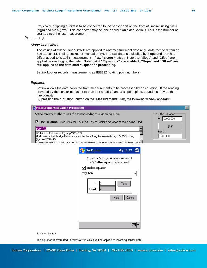
Physically, a tipping bucket is to be connected to the sensor port on the front of Satlink, using pin 9 (high) and pin 5 (low). This connector may be labeled “I2C” on older Satlinks. This is the number of counts since the last measurement.
Processing
Slope and Offset The values of “Slope” and “Offset” are applied to raw measurement data (e.g., data received from an SDI-12 sensor, tipping bucket, or manual entry). The raw data is multiplied by Slope and then has Offset added to it, as in: measurement = (raw * slope) + offset. Note that “Slope” and “Offset” are applied before logging the data. Note that if “Equations” are enabled, “Slope” and “Offset” are still applied to the data after “Equation” processing. Satlink Logger records measurements as IEEE32 floating point numbers.
Equation Satlink allows the data collected from measurements to be processed by an equation. If the reading provided by the sensor needs more than just an offset and a slope applied, equations provide that functionality. By pressing the “Equation” button on the “Measurements” Tab, the following window appears:
Equation Syntax The equation is expressed in terms of "X" which will be applied to incoming sensor data.
Sutron Corporation SatLink2 Logger/Transmitter Users Manual Rev. 7.37 #8800-1149 04/2013 56

You may also reference each measurement by its label which is defined on the Measurement tab. The expression is not case sensitive. The following functions are available: SIN, COS, TAN, ARCTAN, eg COS(90) = 0 SQRT is square root, eg SQRT(9) = 3 To raise a number to a power, multiply it by itself. So, for example, to find x squared, input x*x. EXP, if EXP(x) = y, then LN(y) = x, eg EXP(1) = 2.718282 LN, natural log, eg LN(2.718282) = 1 LOG, 10 based log, eg LOG(10) = 1 INT returns the integral portion of a real number
INT(11.456) = 11.000 INT(-1.345) = -1.000 FRACT returns the fractional portion of a real number.
FRACT(11.456) = 0.456 FRACT(-1.345) = -0.345 ABS returns the absolute value of a real number.
ABS(11.456) = 11.456 ABS(-1.345) = 1.345 POLY is used to compute up to a 5th level polynomial equation: POLY(x, A, B, C, D, E, F) equates to A + Bx + Cx^2 + Dx^3 + Ex^4 + Fx^5 STEINHART(x, A, B, C) is used for Steinhart-Hart equations, where x is the resistance and result is the temperature in Celsius A, B and C are thermistor specific constants Steinhart result is computed like so: 1/(A + B*ln(x) +C*(ln(x)^3)) - 273.15 TIME gets replaced by the number of hours * 100 + number of minutes (HHMM) DATE gets replaced by the Julian date (number of days since year start).
Note: Do not label any measurement time or date, as the measurement would be referenced instead of the TIME and DATE function results
Comparison can be performed using <, >, <=, >=, !=, and =. The result of a comparison is 1 for true or 0 for false. The following bitwise boolean operators are supported: AND, OR, XOR, SHL, and SHR. The last two are shift-left and shift-right. For instance (X SHL 4) would shift X left by 4 bits. AND & OR can also be used in logical expressions. For instance (X>100) OR (X<50) would result in 1 if X is above 100 or below 50; otherwise it would result in 0. The NOT operator is logical not bitwise. This means that NOT 0 is 1 and NOT 1 is 0. Also, the NOT of any non-zero number is 0. eg. (X AND 128) != 0results in a 1 if bit 7 in X is set or 0 if bit 7 is clear. The bit mask 128 is 2^7. This assumes bit 0 is the least significant bit. In general, the bit mask for any bit N is 2^N. PULSE12(A,B) is used to turn on Satlink's Switched +12V output for a short duration. A is a conditional that must be true in order for Satlink to turn on SW +12V. B is the duration to turn on Switched +12V for in milliseconds, with a 10 second maximum. E.g. PULSE12(X>10.5, 500) will turn on Switched +12V for 500 milliseconds if the reading is greater than 10.5. PULSE12 will compute to 1 if Switched +12V was turned on; it will compute to 0 otherwise. If there is an active measurement with an equation that uses PULSE12, the Switched +12V line will NOT be turned on as a part of measurement warmup (VRef will still be turned on). Equations can also contain references to other sensors:eg. (X + AirTemp)/2 would add X to the AirTemp value and divide by 2. Comments can be contained within braces { } {convert from degrees Celsius to degrees Fahrenheit} X*9/5+32 Other examples: SIN(X)+COS(X)+X^3+LOG(X) (X>1000)*1000 + (X<=1000)*X {would limit the value so that it could never be greater than 1000} Troubleshooting: If Satlink claims that the equation is invalid, and the equation contains references to other measurements, try sending the setup to Satlink and then retry testing the equation. The only true test of equation processing is to hit Force Measurement after the equation has been set.
Sutron Corporation SatLink2 Logger/Transmitter Users Manual Rev. 7.37 #8800-1149 04/2013 57
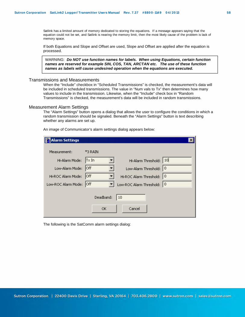
Satlink has a limited amount of memory dedicated to storing the equations. If a message appears saying that the equation could not be set, and Satlink is nearing the memory limit, then the most likely cause of the problem is lack of memory space.
If both Equations and Slope and Offset are used, Slope and Offset are applied after the equation is processed.
Transmissions and Measurements
When the “Include” checkbox in “Scheduled Transmissions” is checked, the measurement’s data will be included in scheduled transmissions. The value in “Num vals to Tx” then determines how many values to include in the transmission. Likewise, when the “Include” check box in “Random Transmissions” is checked, the measurement’s data will be included in random transmissions.
Measurement Alarm Settings The “Alarm Settings” button opens a dialog that allows the user to configure the conditions in which a random transmission should be signaled. Beneath the “Alarm Settings” button is text describing whether any alarms are set up. An image of Communicator’s alarm settings dialog appears below:
The following is the SatComm alarm settings dialog:
WARNING: Do NOT use function names for labels. When using Equations, certain function names are reserved for example SIN, COS, TAN, ARCTAN etc. The use of these function names as labels will cause undesired operation when the equations are executed.
Sutron Corporation SatLink2 Logger/Transmitter Users Manual Rev. 7.37 #8800-1149 04/2013 58

The “Measurement Index” field in Communicator, and the header test in SatComm, display the currently selected index that the alarm settings refer to. There are four different kinds of alarms. A measurement is in alarm when its mode is set to something other than “Off” and its data meets the conditions for alarm (see below). The alarm mode determines when random burst transmissions occur. When the mode is set to “TxIn”, random burst transmissions are signaled when the measurement goes into alarm. When the mode is set to “TxOut”, random burst transmissions are signaled when the measurement goes out of alarm. When the mode is set to “TxBoth”, random burst transmissions are signaled when the measurement goes either into, or out of, alarm. A measurement goes into “Hi-Alarm” when the “Hi-Alarm Mode” is set to something other than “Off” and the measurement’s data goes above “Hi-Alarm Threshold” plus “Deadband”. A measurement goes out of “Hi-Alarm” when the “Hi-Alarm Mode” is set to something other than “Off” and the measurement’s data goes below “Hi-Alarm Threshold” minus “Deadband”. For example, suppose a water level sensor is connected to Satlink Logger, and the Hi-Alarm Threshold is set to 10, with the Deadband set at 2. If the water level exceeds 12 (10 + 2) and the High Alarm Mode is set to either "TxIn" or "TxBoth", then Satlink Logger will send a burst of random transmissions, as defined in the Random Tx section. After finishing its burst of random transmissions, or if the High Alarm Mode were set to "TxOut", Satlink Logger will send random transmissions at a rate derived from the Random Alarm Interval. When the water level falls below 8 (10 – 2), Satlink Logger will send another burst of random transmissions if the mode is set to either "TxOut" or TxBoth". After this, Satlink Logger will resume its random transmissions at the Random Normal Interval. The "Low Alarm" is similar, but now the measurement goes in to “Low-Alarm” when the measurement’s data goes below the “Low-Alarm Threshold” minus “Deadband” and the “Low-Alarm Mode” is set to something other than “Off”. This same measurement goes out of “Low-Alarm” when the measurement’s data goes above “Low-Alarm Threshold” plus “Deadband” and the “Low-Alarm Mode” is set to something other than “Off”. Another type of alarm is the Rate of Change alarms. The “Hi-ROC Alarm” is triggered for a measurement when the “Hi-ROC Alarm Mode” is set to something other than “Off” and the measurement’s data goes above “Hi-ROC Alarm Threshold” plus “Deadband”. A measurement goes out of “Hi-ROC Alarm” when the “Hi-ROC Alarm Mode” is set to something other than “Off” and the measurement’s data goes below “Hi-ROC Alarm Threshold” minus “Deadband”.
Sutron Corporation SatLink2 Logger/Transmitter Users Manual Rev. 7.37 #8800-1149 04/2013 59

Using the previous example, now suppose the user wants to measure how fast the body of water is swelling and send a transmission if the rate of change is above a certain level. With hourly measurements a good "Hi-ROC Alarm Threshold" might be 1.25 with a Deadband of 0.75. The burst, alarm, and normal random transmissions work the same as in the previous example, but this time the measurement enters alarm mode when the data has changed by greater than 2 (1.25 + 0.75), for example from 6 in one measurement to above 8 in the next measurement. It will exit alarm mode when the rate of change falls below 0.5 (1.25 – 0.75), or, for example, when one measurement is 8 and the next less than 8.5. A measurement goes in to “Low-ROC Alarm” when the “Low-ROC Alarm Mode” is set to something other than “Off” and the measurement’s data goes below “Low-ROC Alarm Threshold” minus “Deadband”. A measurement goes out of “Low-ROC Alarm” when the “Low-ROC Alarm Mode” is set to something other than “Off” and the measurement’s data goes above “Low-ROC Alarm Threshold” plus “Deadband”. Because ROC Alarms are timing sensitive, it should be mentioned that measurements are not necessarily made at the exact time they are scheduled, but depend on a variety of factors. The exact time when measurements are made can be viewed on the Diagnostics tab in the debug output window.
Last Data The “Last Data” group allows the user to view the last measured value and to “force” a measurement. This block contains the Data, Time, and Quality information for the most recent measurement. To update these fields with data from the last scheduled measurement, press the “Update” button. The user can also request a measurement be made immediately by pressing the “Force” button. Satlink does not have to be stopped for the measurement to be made. If the forced measurement interferes with any scheduled measurements, Satlink will make the scheduled measurements after completing the forced measurement. While the measurement is in progress, the communicator program polls Satlink Logger for the result. A dialog is displayed allowing the user to cancel this polling process. When the measurement completes, the data, time, and quality fields are updated with the new values, unless polling was cancelled. The user can abort a forced measurement that is in progress by pressing the “Abort” button. Please note that forced measurements will be always made of a single sample, even if averaging is enabled. The “Live Poll” option will allow the continuous forcing of measurements by Communicator. When the button is pressed, a new window will pop up showing the results of the forced measurements. The Communicator can poll at a user set interval.
Sutron Corporation SatLink2 Logger/Transmitter Users Manual Rev. 7.37 #8800-1149 04/2013 60

Measurement Commands The “Set Tipping Bucket Count” button opens a dialog that allows the user to specify a new baseline tipping bucket count. The new count replaces the current count and increments with subsequent tips. The unit must be stopped in order to set the tipping bucket count. When it comes to tipping bucket measurements, there are two numbers to keep in mind. The first one is the raw tip count. This number reflects the physical tips of the tipping bucket. The second number is the measurement of rainfall, which is calculated by applying a slope and an offset to the raw tip count. For example, with one type of tipping bucket, one hundred tips equal one inch of rain. For that tipping bucket the slope would be set to 0.01. While SatComm’s tipping bucket dialog only allows the user to set the raw tip count, Communicator’s tipping bucket dialog allows the user to set either the raw tip count, or the scaled rainfall measurement. So, for our example tipping bucket with 100 tips equaling one inch of rain, if the user wanted to set it to show two inches of rain, he could do so by either setting the tip count to 200, or the scaled number to 2.
Sutron Corporation SatLink2 Logger/Transmitter Users Manual Rev. 7.37 #8800-1149 04/2013 61
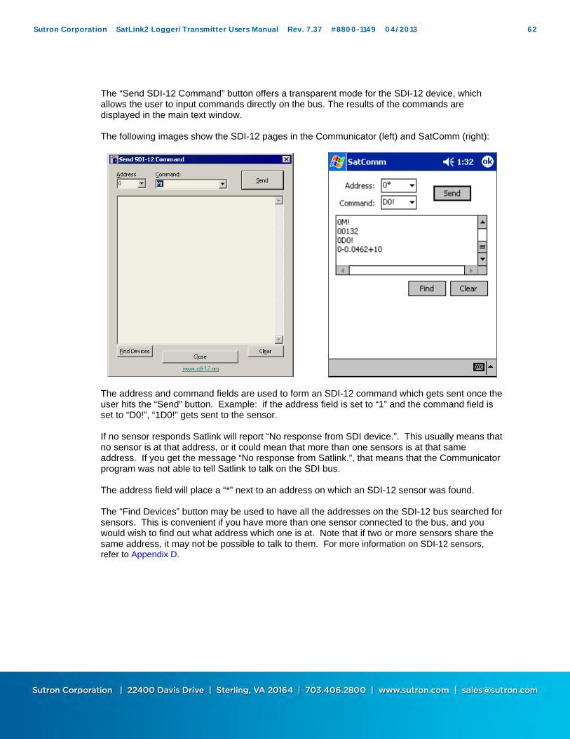
The “Send SDI-12 Command” button offers a transparent mode for the SDI-12 device, which allows the user to input commands directly on the bus. The results of the commands are displayed in the main text window. The following images show the SDI-12 pages in the Communicator (left) and SatComm (right):
The address and command fields are used to form an SDI-12 command which gets sent once the user hits the “Send” button. Example: if the address field is set to “1” and the command field is set to “D0!”, “1D0!” gets sent to the sensor. If no sensor responds Satlink will report “No response from SDI device.”. This usually means that no sensor is at that address, or it could mean that more than one sensors is at that same address. If you get the message “No response from Satlink.”, that means that the Communicator program was not able to tell Satlink to talk on the SDI bus. The address field will place a “*” next to an address on which an SDI-12 sensor was found. The “Find Devices” button may be used to have all the addresses on the SDI-12 bus searched for sensors. This is convenient if you have more than one sensor connected to the bus, and you would wish to find out what address which one is at. Note that if two or more sensors share the same address, it may not be possible to talk to them. For more information on SDI-12 sensors, refer to Appendix D.
Sutron Corporation SatLink2 Logger/Transmitter Users Manual Rev. 7.37 #8800-1149 04/2013 62

DATA
The Data tab allows the user to view the sensor data. The system keeps 32 readings for each of the 16 measurements. The measurements are displayed according to their schedule. If, after changing the measurement schedule, data seems to disappear, it is because measurements are displayed according to the new schedule, even though they were made according to the old schedule.
Sutron Corporation SatLink2 Logger/Transmitter Users Manual Rev. 7.37 #8800-1149 04/2013 63

The "Index" box is used to select the desired measurement to view (1 to 16). When an index is selected, the 32 most recent measurements for that index are displayed. The data for this tab comes from special buffers that hold the data for this display and transmissions. Each measurement is labeled with a timestamp of the requested measurement time, and a quality flag for the measurement. The PC version of the Communicator program allows the user not only to view the 32 most recent readings of a single measurement, but also the last reading of all the active measurements. This selection is accomplished via the radio button labeled “Show Measurements”. Another PC only option is forcing all measurements at once. This is a useful feature that can make sure the measurement setup is proper with the click of a single button. When invoked, Satlink will take a reading of each active measurement and display the results in the data window. If the "Work Connected" option is enabled, the recorded measurements will be automatically updated and displayed when the user first loads the Data tab; however one can also press the "Refresh Data" button to display the most recent data. The "Clear Data" button clears all the last recorded readings without affecting the data log. Since this data is used in transmissions, a transmission after “Clear Data” is pressed will not have data to transmit and will transmit using missing data indicators (M or ///).
Logging Functions Satlink Logger also contains a built-in logging function, which will record the data for measurements with the "Send to Log" box on the Measurements tab checked. The logger will record up to 120,000 measurements including the time and quality stamps. After this, the logger will begin overwriting its oldest data. In order to access the data recorded in the log one must download the log from Satlink Logger. Pressing the "Export Log" button on the “Data” tab or on the “Tools” menu will bring an export dialog. Communicator’s export dialog appears below left, while SatComm’s dialog appears below right:
Sutron Corporation SatLink2 Logger/Transmitter Users Manual Rev. 7.37 #8800-1149 04/2013 64

As you can see, Satlink Logger allows for portions of the log to be downloaded by selecting the appropriate button. One can also reset the data in the log by pressing the "Clear Log" button on the data tab. Note that clearing the log permanently destroys all logged data. Communicators version 3.30 and newer are able to specify the download baud rate. Clicking “Modem/Bluetooth support” will download the log at a slower 9600 baud (as opposed to 115200 baud). Normally, Satlink talks at 9600, but the log download is done at 115200 baud. Switching baud rates will break the connection if the user is connected via modem or Bluetooth unless the “Modem/Bluetooth support” option is selected. NOTE: 'Open log file after download' on the Communicator will use the default windows program for .csv files (generally Microsoft Excel), whereas SatComm will use Pocket Word. Pocket Word will turn on 'Wrap to window' by default, if you cannot see any data in the Word window, uncheck 'Wrap to window' from the VIEW toolbar. The log formats determine how the data is formatted in the .csv file. Note that raw data is downloaded from Satlink (to SatlinkTempLog.raw) and then reformatted to a .csv file. Here are examples of the different log formats: Satlink Standard log format Analog,10/30/2005,06:36:03,1242.821655,Good
Sutron Corporation SatLink2 Logger/Transmitter Users Manual Rev. 7.37 #8800-1149 04/2013 65

Analog,10/30/2005,06:36:04,1242.815430,Good Analog,10/30/2005,06:36:05,1242.826660,Good Analog,10/30/2005,06:36:06,1242.813232,Good Analog,10/30/2005,06:36:07,1242.824219,Good Analog,10/30/2005,06:36:08,1242.843994,Good Analog,10/30/2005,06:36:09,1242.797119,Good Analog,10/30/2005,06:36:10,1242.821655,Good Analog,10/30/2005,06:36:11,1242.824219,Good Analog,10/30/2005,06:36:12,1242.826172,Good Analog,10/30/2005,06:36:13,1242.821411,Good Analog,10/30/2005,06:36:14,1242.809937,Good Analog,10/30/2005,06:36:15,1242.827393,Good Analog,10/30/2005,06:36:16,1242.830200,Good Satlink Standard format is comma delimited. It will put the measurement label, the date of the measurement, the time of the measurement, the value of the measurement, and the quality (Good, Bad or Undefined) on each line. Every single measurement has its own line. Sequential B log format Satlink Sequential Log Format for Station Alive2 from 01/01/2000 to 01/19/2006 ,01/01/2000,Alive2, Analog , 1242.837,00:02:45 Analog , 1242.802,00:02:50 Analog , 1242.809,00:03:10 Analog , 1242.803,00:03:15 ,01/12/2006,Alive2, Analog , 1242.797,02:47:40 Analog , 1242.772,02:47:45 Analog , 1242.806,02:47:50 Analog , 1242.795,02:47:55 Analog , 1242.823,02:48:00 Analog , 1242.813,02:48:05 Analog , 1242.797,02:48:10 The sequential B format is comma delimited and fixed width. It starts with a file header showing the station name and the time span of the data. Every day of data will start with a date identification which is two spaces followed by the date followed by the station name. Every measurement reading has its own line. The line starts with the measurement label and is followed by spaces to fill a column 10 bytes wide. The measurement value follows; it is up to 7 digits and it fills a column 12 bytes wide. Measurement time completes the entry. Sutron Standard CSV log format 10/30/2005,06:36:03,Analog,1242.821655,,Good 10/30/2005,06:36:04,Analog,1242.815430,,Good 10/30/2005,06:36:05,Analog,1242.826660,,Good 10/30/2005,06:36:06,Analog,1242.813232,,Good 10/30/2005,06:36:07,Analog,1242.824219,,Good The Sutron Standard CSV format was introduced in the Summer of 2009. It is a format common to current Sutron products. On Satlink, the format takes the following shape: mm/dd/yyyy,hh:mm:ss,label,data,,quality The general format specification for Sutron Standard CSV format is mm/dd/yyyy,hh:mm:ss,label,data[,units,qual][,label,data[,units,qual]]
To get log files from the Pocket PC device onto another computer
Sutron Corporation SatLink2 Logger/Transmitter Users Manual Rev. 7.37 #8800-1149 04/2013 66
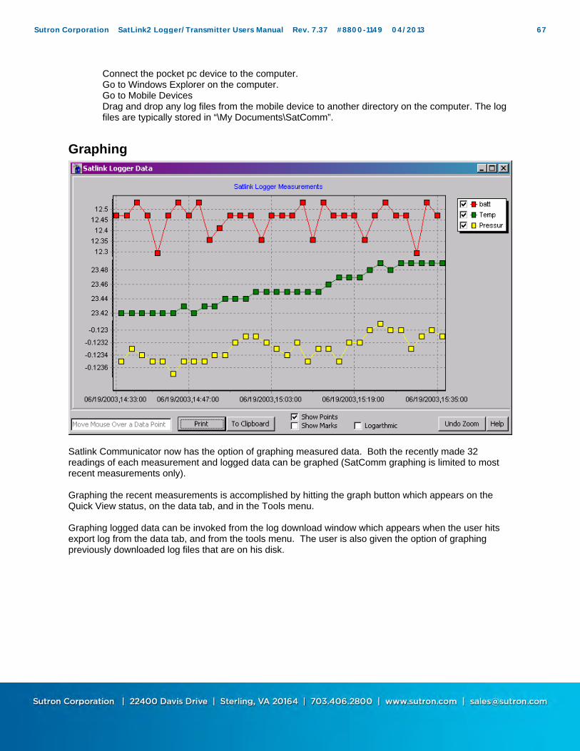
Connect the pocket pc device to the computer. Go to Windows Explorer on the computer. Go to Mobile Devices Drag and drop any log files from the mobile device to another directory on the computer. The log files are typically stored in “\My Documents\SatComm”.
Graphing
Satlink Communicator now has the option of graphing measured data. Both the recently made 32 readings of each measurement and logged data can be graphed (SatComm graphing is limited to most recent measurements only). Graphing the recent measurements is accomplished by hitting the graph button which appears on the Quick View status, on the data tab, and in the Tools menu. Graphing logged data can be invoked from the log download window which appears when the user hits export log from the data tab, and from the tools menu. The user is also given the option of graphing previously downloaded log files that are on his disk.
Sutron Corporation SatLink2 Logger/Transmitter Users Manual Rev. 7.37 #8800-1149 04/2013 67

On the graphing window itself, the user is allowed to select which measurements to graph, to do logarithmic scaling, to examine the graph data in detail (by zooming), to print the graph, and copy the graph to the clipboard as a bitmap (which can be pasted into certain programs such as Microsoft word). Zooming into the data points is accomplished by left clicking and dragging from left to right anywhere in the graph data window. Zooming out is accomplished in a fashion similar to zooming in, except that the dragging is done from right to left. Scrolling is done by right clicking and dragging. In Communicator, Graphing can be invoked from the Quick View Status, from the Tools menu, from a button on the Data tab, or by selecting the “Graph data after download” checkbox on the log details dialog. In SatComm, graphing is invoked from the Tools menu only.
Sutron Corporation SatLink2 Logger/Transmitter Users Manual Rev. 7.37 #8800-1149 04/2013 68
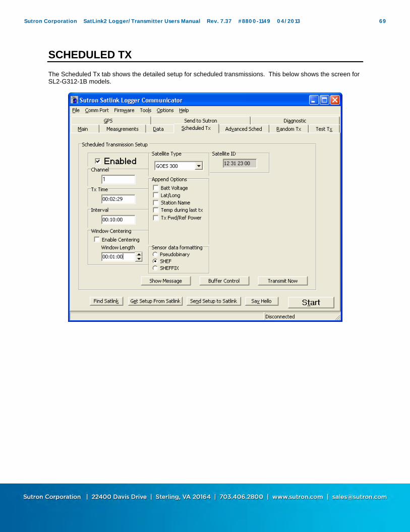
SCHEDULED TX
The Scheduled Tx tab shows the detailed setup for scheduled transmissions. This below shows the screen for SL2-G312-1B models.
Sutron Corporation SatLink2 Logger/Transmitter Users Manual Rev. 7.37 #8800-1149 04/2013 69

Sutron Corporation SatLink2 Logger/Transmitter Users Manual Rev. 7.37 #8800-1149 04/2013 70

The screen shot below represents the selections for SL2-G312-V2 models only. Note the addition of new satellite types and antenna selections. The selections made will determine the transmit power to ensure the correct power levels being uplinked to the satellites.
Below are the satellite selections found in the drop down box.
Notice that the GOES 300 and 1200 bps have 2 options now. There is a G11/12 and a G13+ option. This represents the satellite series in use by NESDIS. Currently Goes 11 is the operational West satellite and Goes 12 is not being used for DCS. Goes 13, which is the newer design satellite currently stationed as the GOES East satellite, has an approximately 6 dB performance improvement in operation over the prior satellites from G1 thru G12. This means less transmitter power is required on the newer G13 and newer satellites to achieve the same performance as previously done on G1-G12. At the time of this
Sutron Corporation SatLink2 Logger/Transmitter Users Manual Rev. 7.37 #8800-1149 04/2013 71
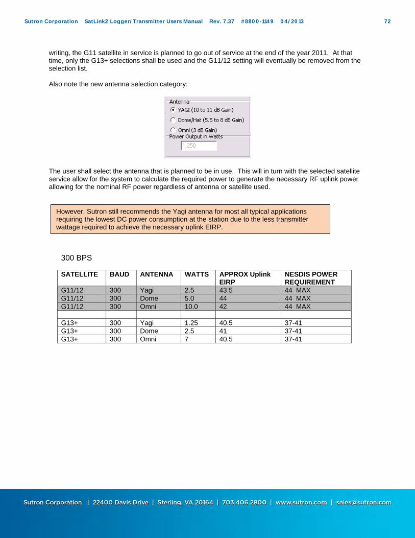
writing, the G11 satellite in service is planned to go out of service at the end of the year 2011. At that time, only the G13+ selections shall be used and the G11/12 setting will eventually be removed from the selection list. Also note the new antenna selection category:
The user shall select the antenna that is planned to be in use. This will in turn with the selected satellite service allow for the system to calculate the required power to generate the necessary RF uplink power allowing for the nominal RF power regardless of antenna or satellite used.
300 BPS
SATELLITE BAUD ANTENNA WATTS APPROX Uplink EIRP
NESDIS POWER REQUIREMENT
G11/12 300 Yagi 2.5 43.5 44 MAX G11/12 300 Dome 5.0 44 44 MAX G11/12 300 Omni 10.0 42 44 MAX G13+ 300 Yagi 1.25 40.5 37-41 G13+ 300 Dome 2.5 41 37-41 G13+ 300 Omni 7 40.5 37-41
However, Sutron still recommends the Yagi antenna for most all typical applications requiring the lowest DC power consumption at the station due to the less transmitter wattage required to achieve the necessary uplink EIRP.
Sutron Corporation SatLink2 Logger/Transmitter Users Manual Rev. 7.37 #8800-1149 04/2013 72
1200 BPS
SATELLITE BAUD ANTENNA WATTS APPROX Uplink EIRP
NESDIS POWER REQUIREMENT
G11/12 1200 Yagi 10 49.5 50 MAX G11/12 1200 Dome 10 47 50 MAX G11/12 1200 Omni 14 42 50 MAX G13+ 1200 Yagi 5 46.5 43-47 G13+ 1200 Dome 10 47 43-47 G13+ 1200 Omni 14 43.5 43-47
NOTE** The shaded selections will be discontinued approximately at the end of 2011.
Transmission Channel Settings 300 BPS A significant change has been made to the Model SL2-G312-V2 model as it now supports a new channel definition with respect to the SL2-G312-1B and earlier models. The new channnel scheme for 300 BPS has the exact same channel frequency assignments from 1-266 although there is the addition of new channels 301-566. This is referred to as splitting the channels as the original channel bandwidth has been reduced from 1.5KHz to 750 Hz. V1.0B (original HDR) CH 1-266 1.5 KHz Channel Bandwidth
1 2 3 …266
V2.0 (new V2 standard) CH 1-266 and 301-566 750 Hz Channel Bandwidth
1 301 2 303 3 … 266 566
NOTE: All channels from 1 – 266 have the exact same center frequency for both V1.0B and V2 systems. This means that new and old transmitters will be able to use the same channels from 1-266. Only the new V2 transmitters can use the new ‘inbetween’ channels of 301-566. NESDIS will control the channel assignments.
Sutron Corporation SatLink2 Logger/Transmitter Users Manual Rev. 7.37 #8800-1149 04/2013 73
1200 BPS The change in channelization for 1200 bps between SL2-G312-1B and SL2-G312-V2 is more significant. The SAME channel numbers are now used for the 1200 bps although not every channel is permitted to be a a 1200 bps channel. See below for which 1200 bps channels are permitted. V1.0B (original HDR) CH 1A-133A 3.0 KHz Channel Bandwidth
1A 2A 3A …133A
V2.0 (new V2 standard) CH 1-266 and 301-566** 2250 Hz Channel Bandwidth
301 3 304 6 307 … 264 565
** only selected channel numbers are permitted. (3,6,9,12…261,264) and (301,304,307…562,565) **NOTE: The channel numbers DO NOT MATCH for the V1.0B and V2 systems. NESDIS will provide the proper channel number when they begin to assign V2 channels. It will be critical for the customer to be aware whether he is using a V2 certified unit or a V1.0B certified unit and convey that information to NESDIS officials providing the channel assignments.
Sutron Corporation SatLink2 Logger/Transmitter Users Manual Rev. 7.37 #8800-1149 04/2013 74
Transmission Settings If scheduled transmissions are enabled by checking the “Enabled” box, then timed transmissions will occur at a regular interval. The scheduled transmissions are configured by filling out the fields on the Scheduled Tx tab. The Transmission time (Tx Time) , Interval, Channel and Satellite Type are assigned by the appropriate authority which manages the airwaves to be unique for each transmitter. NESDIS manages the details for all GOES transmissions. On this page the Satellite ID cannot be changed. Go to the Main tab to change the ID. All the transmission times for Satlink Logger are in the format of HH:MM:SS. The "Append Options" attach additional information to the data transmitted, Batt Voltage and Lat/Long will be appended regardless of the formatting type, but “Station Name” and “Temp during last tx” will only if the “Sensor data formatting” is set to SHEF or SHEFFIX. The extra information is appended after external data (which is appended after sensor data). The battery voltage was measured during the last transmission (under load). Therefore the first transmission after bootup will report battery voltage of zero. If “Lat/Long" checkbox is marked, the coordinate information will be added to the end of the transmission. If SHEF or SHEFFIX is used to encode the transmission, the latitude and longitude will be in a readable format. If Pseudobinary is used, the information will be encoded into an 8-byte value. The formula for decoding this is located in Appendix E. “Station Name” will appear in the message just as it does on the “Main” tab of the Communicator. “Temp during last tx” is the temperature recorded by Satlink prior to the last transmission. “Fwd/Ref” power is the power level in Watts from the last scheduled transmission. Window centering can be enabled for a scheduled transmission using the check box and associated interval. The length defines how much time is allowed for a transmission from the station. When centering is enabled, the transmitter will look at the length of each message that is sent and delay sending the message until it is centered in the transmission window. For example, a transmission which last 10 seconds which is scheduled for the top of the hour and has a window of one minute, would start 25 seconds past the hour.
Data Formatting The "Sensor data formatting" box sets the format that Satlink Logger uses on the data it collects through measurements. This value does not affect data received from an external source. There are three different format types: "SHEF", "SHEFFIX", “Pseudobinary”, “ASCII Column”, and “ASCII Sensor”. Each has it's own distinctive advantages. "SHEF" formats the data into readable ASCII messages. "SHEFFIX" is just a modified version of "SHEF" where the data is positioned in fixed spacing so that it will line up better when displayed. However, both the SHEF and SHEFFIX formats generally create long messages. The “Pseudobinary" format encodes the data into 3 characters that you cannot read without the aid of a program. This format is over 50% shorter than the SHEF and SHEFFIX formats which results in shorter transmissions and lower power consumption. Although it is much harder for a person to visually inspect the data in this format, it is a much more efficient format for sending data. “ASCII Column” and “ASCII Sensor” formats are similar to SHEF in that they create human readable and lengthy messages. “ASCII Column” transposes the data, showing data from different sensors on each line. The columns will have data from the same sensor. “ASCII Sensor” mode formats each sensor reading into four digits after multiplying the reading by 100. No decimal point is used in this format.
Sutron Corporation SatLink2 Logger/Transmitter Users Manual Rev. 7.37 #8800-1149 04/2013 75
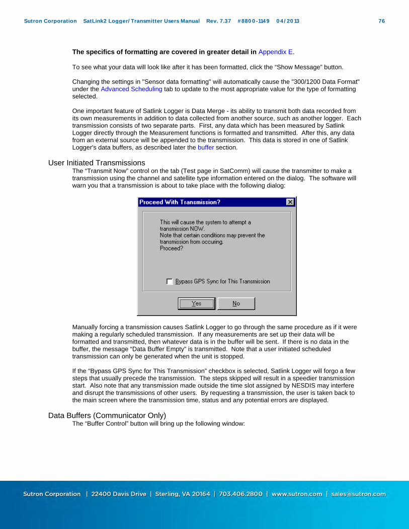
The specifics of formatting are covered in greater detail in Appendix E. To see what your data will look like after it has been formatted, click the “Show Message” button. Changing the settings in "Sensor data formatting" will automatically cause the "300/1200 Data Format" under the Advanced Scheduling tab to update to the most appropriate value for the type of formatting selected. One important feature of Satlink Logger is Data Merge - its ability to transmit both data recorded from its own measurements in addition to data collected from another source, such as another logger. Each transmission consists of two separate parts. First, any data which has been measured by Satlink Logger directly through the Measurement functions is formatted and transmitted. After this, any data from an external source will be appended to the transmission. This data is stored in one of Satlink Logger's data buffers, as described later the buffer section.
User Initiated Transmissions The “Transmit Now” control on the tab (Test page in SatComm) will cause the transmitter to make a transmission using the channel and satellite type information entered on the dialog. The software will warn you that a transmission is about to take place with the following dialog:
Manually forcing a transmission causes Satlink Logger to go through the same procedure as if it were making a regularly scheduled transmission. If any measurements are set up their data will be formatted and transmitted, then whatever data is in the buffer will be sent. If there is no data in the buffer, the message “Data Buffer Empty” is transmitted. Note that a user initiated scheduled transmission can only be generated when the unit is stopped. If the “Bypass GPS Sync for This Transmission” checkbox is selected, Satlink Logger will forgo a few steps that usually precede the transmission. The steps skipped will result in a speedier transmission start. Also note that any transmission made outside the time slot assigned by NESDIS may interfere and disrupt the transmissions of other users. By requesting a transmission, the user is taken back to the main screen where the transmission time, status and any potential errors are displayed.
Data Buffers (Communicator Only) The “Buffer Control” button will bring up the following window:
Sutron Corporation SatLink2 Logger/Transmitter Users Manual Rev. 7.37 #8800-1149 04/2013 76

Satlink Logger's data buffer contains all of the external data that Satlink Logger receives from another source, such as another logger. This window will allow the user to examine, clear and append the data in Satlink Logger’s Scheduled and Random buffers. Choosing a value in “Buffer” will allow the user to select which of Satlink Logger's data buffers to inspect. The buffers are independent of each other. Any commands issued to Satlink Logger through this dialog will affect only the selected buffer. Hitting the “View Data in Satlink's Buffer” will read the data and display it for the user. Using this command will not affect the data in Satlink Logger's buffer. The “Clear Data in Satlink's Buffer” is used to delete all the data in Satlink Logger's buffer. “Append Data to Satlink's Buffer” will take the data displayed in the window, and append it to Satlink Logger's buffer. Use the “Load from File” to put data from a file into the window, and use the “Save to File” to save the data currently displayed in the window to a file. Hitting the “Clear” button will only clear the data in the window, and will not affect the data in Satlink Logger's buffer. “Buffer Size” will always indicate the size of Satlink Logger's buffer (this is the maximum number of bytes that can fit into Satlink Logger's buffer). “Data Bytes in Buffer” displays the number of bytes currently in Satlink Logger's buffer. The data may be displayed as ASCII or hexadecimal (by selecting the appropriate “Display Data As” radio button).
Transmission Message (Communicator Only) The “Show Message” button will bring up a window that will show what a scheduled transmission message would look like. If the user is interested in finding out how long the transmission is, this is the place to find out. Satlink formats up the message just as if it were about to do a transmission, and then shows that message to the user. This means that it includes sensor data, external data, and any appended data (battery voltage, latitude and longitude). This window contains other helpful information too. The length of the transmission (in bytes and seconds) is calculated and shown to the user. The user is informed how much of the data is sensor data, and how much of the transmission the sensor data could possibly take up is also shown. A message may vary in length, depending on the type of sensor formatting selected. SHEFFIX and pseudobinary formatting result in fixed length data. However, SHEF messages vary in length. This is
Sutron Corporation SatLink2 Logger/Transmitter Users Manual Rev. 7.37 #8800-1149 04/2013 77

because the number of digits in a reading (12.5 opposed to 125.5), and because the first few transmissions are likely to have missing data (which is formatted as ‘M’). In this window, Satlink also tells the user how many measurements are active and how many readings are set to be transmitted. These settings can be modified in the Measurement Tab (see section Transmissions and Measurements page 58). This is what a transmission data window will look like:
Sutron Corporation SatLink2 Logger/Transmitter Users Manual Rev. 7.37 #8800-1149 04/2013 78
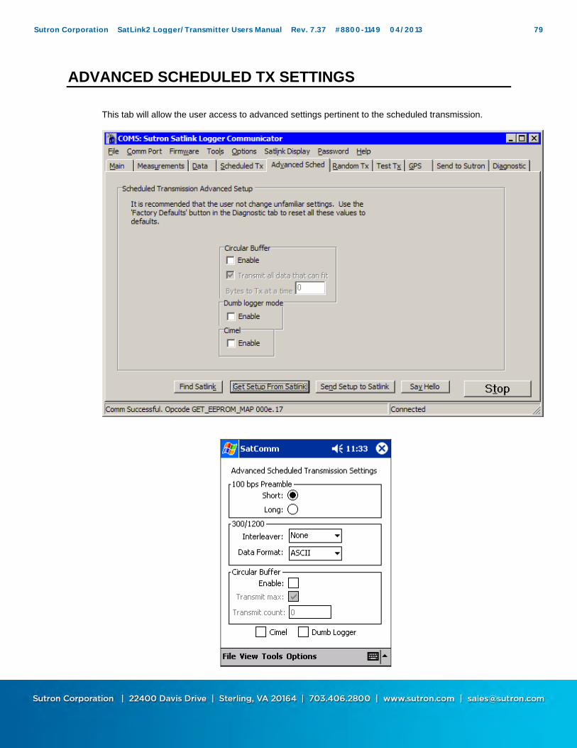
ADVANCED SCHEDULED TX SETTINGS
This tab will allow the user access to advanced settings pertinent to the scheduled transmission.
Sutron Corporation SatLink2 Logger/Transmitter Users Manual Rev. 7.37 #8800-1149 04/2013 79
There are two group boxes that are relative to the Satellite Type. The “100bps Preamble” box gives the user the options of “Short” or “Long” preamble. A short preamble will result in the transmission having a much shorter carrier length. This setting has been removed with version 6.32. The “300/1200 Interleaver” can be set to either “None”, “Short”, or “Long”. Setting the interleaver to “Short” or “Long” will cause any potential errors in the transmission to be spread out over the whole message, thus allowing for an easier error correction. Typical transmissions only need to use the default, or "None" interleaver. This setting has been removed with version 6.32. It is strongly recommended that the user does not change the "300/1200 Data Format" setting. This will not affect how the data from Satlink Logger's sensors is formatted. Instead use the "Sensor Data Formatting" box under the Scheduled Tx tab to select a format type (SHEF, Pseudobinary, etc.). This will automatically set the "300/1200 Data Format" to appropriate values for the desired format. This setting has been removed with version 6.32. Circular Buffers allow different handling of the data in Satlink Logger's buffer. If they are enabled, Satlink Logger will transmit only so much data every time, and keep the rest for the next transmission. If a number of bytes to be transmitted is specified (“Bytes to Tx at a time”), then Satlink Logger will transmit only that many bytes, and leave the rest of the data in the buffer for the next transmission. If “Transmit all data that can fit” is selected, then Satlink Logger will transmit all the data that can fit into the transmission. (All transmissions are time limited). If Circular Buffers are not enabled, Satlink Logger will throw away any data it cannot fit into the transmission.
Dumb Logger Mode The “Dumb Logger” mode is used to have Satlink transmit data from a logger that does not speak the Satlink serial port communications protocol. If this mode is enabled, any data coming into the serial port that is not of Satlink protocol gets put into the scheduled transmission buffer. In order for Satlink to accept data from another logger, besides having the dumb logger mode enabled, the user must ensure that the logger talk at 9600 bps, 8 data bits, no parity, one stop bit, no flow control. There are two ways to wake Satlink up: either assert RTS or send a wake up character. That wake up character should be binary 0. After waking Satlink make sure to wait at least 6 milliseconds. After Satlink is woken, it will acknowledge by asserting CTS. If woken with a character, Satlink will stay awake for five seconds after the last character comes in. If woken with an RTS, Satlink will stay awake for as long as RTS is asserted. Note that you are likely to need a null modem in order to connect logger to Satlink. It is actually possible to send data to Satlink without a wakeup character or RTS. What happens is this: Satlink is sleeping whilst keeping its clock running at 600kHz (min speed required to talk 9600). This pulls about 0.1mA more than non dumb logger sleep. Once Satlink gets the first incoming character, it wakes and takes about 6ms to restore its clock to normal frequencies. During this time, any incoming characters may get corrupted. As long as more than 6ms pass between the first and the second chars, Satlink catches all of them. In some cases, if the chars are very close together, Satlink will catch them all before speeding up his clock. Since RS232 does not guarantee the in-between character timing, success depends on the connected device. The “Cimel” mode should be used when Satlink is to collect data from a CIMEL logger. In this mode Satlink will, prior to transmission (at the same time it does the GPS satellite acquisition), grab data from CIMEL and treat it as it does external data. For more information on external data see the buffer section.
Sutron Corporation SatLink2 Logger/Transmitter Users Manual Rev. 7.37 #8800-1149 04/2013 80

RANDOM TX
This tab defines how to send random or unscheduled transmissions. A diagram is shown below. (NOTE: See scheduled section above to see the added menu fields for the SL2-G312-V2.)
Sutron Corporation SatLink2 Logger/Transmitter Users Manual Rev. 7.37 #8800-1149 04/2013 81

If they are enabled, how often random transmissions occur depends upon the alarm status. Alarms can be set up for individual sensors through the Measurements tab under the "Alarm Settings." If the sensors are not in alarm, Satlink Logger will make transmissions at a rate determined by the "Normal Interval". When the sensor enters and/or exits alarm mode, Satlink Logger will make a series of transmissions called a burst. The number of transmissions in a burst is defined by the user. Normally, alarm transmissions are repeated multiple times because there is no guarantee that a single message will make it through. It is common to set the "Number of Tx per Burst" (“Num Bursts” in SatComm) to 3 to increase the chance that the alarm gets through. The "Burst Interval" defines how much time passes between attempted transmissions. Note that if a second sensor enters alarm mode while the first sensor is waiting for a burst, the first sensor’s bursts will be cancelled and the second sensor will begin its bursts. For more information on how to set up burst transmissions see the Alarms section of the manual. While any sensor is in alarm and burst transmissions are finished, Satlink Logger will transmit at the rate set by “Alarm Interval”. The Random Transmission Setup also defines the Channel, Satellite Type and ID, and the "Append Lat/Long" checkbox. These values are similar to their scheduled transmission counterparts but apply to random transmissions and channels. Note that the Satellite ID is shared with scheduled transmissions; it is not possible to set up a different ID for scheduled and random transmissions. On this page the Satellite ID cannot be changed. Go to the Main tab to change the ID. "Transmit Now" and "Buffer Control" also work the same as would a scheduled transmission, with the exception that a random transmission can also be forced, either manually or by a signal from another logger unit, while the system is running. The channel and BPS for a forced transmission will reflect the values chosen for random transmissions.
Sutron Corporation SatLink2 Logger/Transmitter Users Manual Rev. 7.37 #8800-1149 04/2013 82

TRANSMITTER TEST (COMMUNICATOR ONLY)
This tab allows the user to exercise the transmitter to verify all its functions. It is also useful when trying to troubleshoot difficult problems. (NOTE: See scheduled section above to see the added menu fields for the SL2-G312-V2.)
The Test Tx functions should only be performed by someone trained in the operation of the transmitter. They should never be done with an antenna connected as the tests can disrupt the transmissions from other stations. Warning: Never perform tests with the antenna connected as violation of transmission assignments may occur. To make test transmissions, first select the “Satellite Type”, the “Transmission Type”, and the “Channel”. Select “Mute Power Amp” if you want to test the modulator board without turning on the amplifiers. After making the selections, press Start Transmission. The following window will show:
Sutron Corporation SatLink2 Logger/Transmitter Users Manual Rev. 7.37 #8800-1149 04/2013 83

The transmission can be left on for observing the signals using scopes and analyzers. To turn off the transmission, hit OK. If you do not stop the transmission in time, the failsafe will trip.
Sutron Corporation SatLink2 Logger/Transmitter Users Manual Rev. 7.37 #8800-1149 04/2013 84

GPS
The details of the GPS tab are as follows:
Sutron Corporation SatLink2 Logger/Transmitter Users Manual Rev. 7.37 #8800-1149 04/2013 85
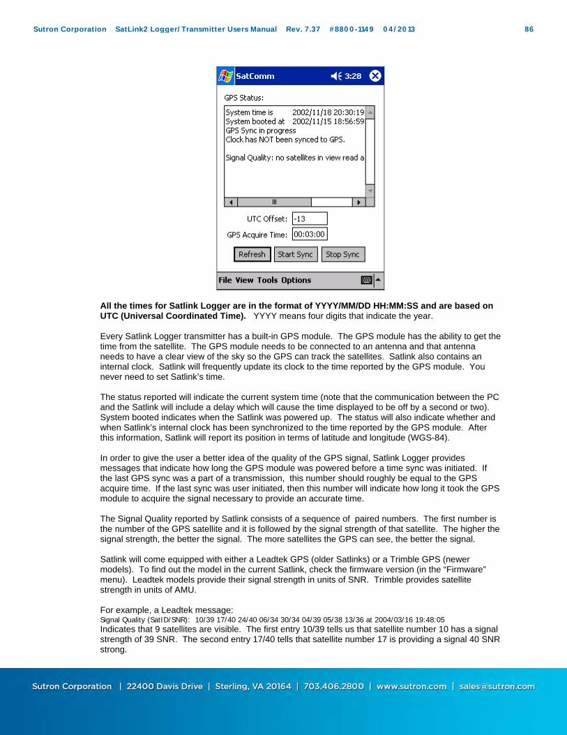
All the times for Satlink Logger are in the format of YYYY/MM/DD HH:MM:SS and are based on UTC (Universal Coordinated Time). YYYY means four digits that indicate the year. Every Satlink Logger transmitter has a built-in GPS module. The GPS module has the ability to get the time from the satellite. The GPS module needs to be connected to an antenna and that antenna needs to have a clear view of the sky so the GPS can track the satellites. Satlink also contains an internal clock. Satlink will frequently update its clock to the time reported by the GPS module. You never need to set Satlink’s time. The status reported will indicate the current system time (note that the communication between the PC and the Satlink will include a delay which will cause the time displayed to be off by a second or two). System booted indicates when the Satlink was powered up. The status will also indicate whether and when Satlink’s internal clock has been synchronized to the time reported by the GPS module. After this information, Satlink will report its position in terms of latitude and longitude (WGS-84). In order to give the user a better idea of the quality of the GPS signal, Satlink Logger provides messages that indicate how long the GPS module was powered before a time sync was initiated. If the last GPS sync was a part of a transmission, this number should roughly be equal to the GPS acquire time. If the last sync was user initiated, then this number will indicate how long it took the GPS module to acquire the signal necessary to provide an accurate time. The Signal Quality reported by Satlink consists of a sequence of paired numbers. The first number is the number of the GPS satellite and it is followed by the signal strength of that satellite. The higher the signal strength, the better the signal. The more satellites the GPS can see, the better the signal. Satlink will come equipped with either a Leadtek GPS (older Satlinks) or a Trimble GPS (newer models). To find out the model in the current Satlink, check the firmware version (in the “Firmware” menu). Leadtek models provide their signal strength in units of SNR. Trimble provides satellite strength in units of AMU. For example, a Leadtek message: Signal Quality (SatID/SNR): 10/39 17/40 24/40 06/34 30/34 04/39 05/38 13/36 at 2004/03/16 19:48:05 Indicates that 9 satellites are visible. The first entry 10/39 tells us that satellite number 10 has a signal strength of 39 SNR. The second entry 17/40 tells that satellite number 17 is providing a signal 40 SNR strong.
Sutron Corporation SatLink2 Logger/Transmitter Users Manual Rev. 7.37 #8800-1149 04/2013 86

A Trimble message would look like this: Signal Quality (SatID/Signal AMU): 5/4 6/3 10/6 17/4 24/6 at 2004/03/16 19:44:10 Five satellites are visible. 5/4 means satellite number 5 is providing a signal with a strength of 4 AMU. The lowest useful signal strength is 2 AMU. Last frequency discipline result, as reported in the GPS status, shows the compensation made by Satlink in order to overcome drift by its oscillator. Satlink automatically compensates for any drift of the oscillator used to create the transmission frequency by measuring the oscillator against the ultra accurate one Hz signal coming from the GPS. The "Start GPS Sync" button (“Start Sync” in SatComm) forces the Satlink Logger to begin acquiring the time and location information from GPS. After pressing “Start GPS Sync” the text box will report on the status of the calibration test when it is refreshed. Typically, the system will take 30 to 45 seconds to acquire position fix information and 10 to15 seconds to acquire time. If the system takes longer than this to acquire the time, you may need to reposition the GPS antenna. As a last resort, you may need to increase the acquire time to allow the station more time to acquire signals from the GPS satellites. Use the button labeled “Stop GPS Sync” (“Stop Sync” in SatComm) to stop a user initiated GPS acquisition. “Get GPS Status” (“Refresh” in SatComm) should be used to refresh the GPS information shown. Note that as long as Auto Update is selected from the Options menu, the Communicator program will do this automatically every few seconds. The field labeled UTC offset tells Satlink the difference between UTC and GPS time. This field is only applicable to Satlinks with a GPS module version LD03. UTC and GPS time will drift after an extended time period. At the original time of writing (March 2004) this offset was -13 seconds. It changed to -14 January 1st 2006. A change to -15 is scheduled for Jan 1st 2009. Trimble GPS UTC offset (leap second) bug There is a bug in the Satlink Trimble GPS that causes Satlink's clock to be one second late. The bug affects Satlinks active during the time period between August 2008 and Jan 1st 2009. After Jan 1st 2009, the bug will not manifest until the next leap second change. The bug is caused by software inside the Trimble GPS that prematurely applies the GPS to UTC offset. The offset changes Jan 1st 2009. The GPS units think it changes in Aug 2008. This same bug had previously manifested between Aug 2005 and Jan 1st 2006. There are two ways to fix the problem: 1) Satlink firmware 6.32 will not allow the incorrect offset to be applied. However, the next time that GPS and UTC time drift by one second, the bug will re-manifest. The previous drift occurred in 2006. When the next will happen is unknown although past trends indicate about every 2-3 years. 2) The software inside the Trimble GPS can be upgraded. To do so, please download the latest Satlink install package from www.sutron.com. Once installed, run Satlink Communicator, and follow on screen instructions. Communicator will guide you through the entire upgrade process. Trimble GPS Versions:
Old buggy version: Trimble Nav 1.4 01/23/03 Sig 2.12 06/10/02 New fixed version: Trimble Nav 1.6 09/26/05 Sig 2.12 09/13/05 Never affected by bug: Trimble Nav 1.16 (shipped starting 2009)
To verify version, run Satlink Communicator and click menu Firmware->Check Version. To upgrade, you will need: (all provided with SatlinkInstall.exe available from www.sutron.com) Satlink2 version 6.36 Satlink Logger Communicator 3.38 If a Satlink Display is in use, SD Display requires version 3.38, plain Display 2.08 Trimble upgrader software (TrimbleMon.exe) and upgrade file (sq.rom)
Sutron Corporation SatLink2 Logger/Transmitter Users Manual Rev. 7.37 #8800-1149 04/2013 87
How to upgrade Communicator will automatically notify of a new upgrade when connected to Satlink. You may also use Menu Firmware->Upgrade. Communicator will guide you though the upgrade process Once procedure is complete, verify GPS version is Trimble Nav 1.6
V2.0 Certification impact to Satlink Satlink has now been certified under the new V2 rules to operate without GPS for up to 30 days. This is accomplished by the use of a highly stable oven controlled crystal oscillator (OCXO) coupled with discipline techniques. There are several important notes about operation without GPS. These are:
Satlink will NOT perform a single scheduled transmission until at least one successful GPS lock is achieved under any regular operational sense. This ensures that the system has the precise time required to allow the system to transmit. This also serves to verify that the GPS reception is good upon installation and therefore one is not likely to leave a remote station without confirming proper GPS operation.
Satlink MUST successfully make 5 transmissions on a scheduled basis at a minimum before
a transmission may be made without GPS reception. Once the transmissions begin without GPS, they may continue for up to 30 days. If a momentary return of GPS successfully updates the system, the 30 day counter resets.
Sutron Corporation SatLink2 Logger/Transmitter Users Manual Rev. 7.37 #8800-1149 04/2013 88

SEND TO SUTRON (SATCOMM TEST)
Sutron Corporation SatLink2 Logger/Transmitter Users Manual Rev. 7.37 #8800-1149 04/2013 89

The Send to Sutron tab in Communicator, and the Send-To-Sutron Test Transmission portion of the SatComm Test page, are used to send a transmission over the air using the Channel and Satellite ID assigned to Sutron Corp. This function is to be used to make sure that Satlink Logger is working properly. As Sutron Corp. will receive the message, the user needs to be in touch with customer support before using this feature. The “Satellite Type”, “Satellite ID” and “Channel” settings should be set to those belonging to Sutron Corp., not to those belonging to the customer. Hit the Send to Sutron button to initiate a transmission. The program will then prompt you for confirmation, and return to the Main tab where the status of the send to Sutron transmission will be shown. The transmission may or may not start immediately, depending on what Satlink Logger is doing at the time. Note that the system needs to be stopped in order for test transmissions to take place. SatComm also allows the user to send a test transmission using the current scheduled transmission parameters using this page. The button “Send” is used to send the contents of the Message window. Stop Satlink before sending a message in this fashion.
Sutron Corporation SatLink2 Logger/Transmitter Users Manual Rev. 7.37 #8800-1149 04/2013 90

Satellite Test Channels NESDIS currently supports the following channels for manufacturing testing. Any transmission must be coordinated with customer service using these channels as these channels are subject to change. GOES East 100/300 bps Auto Detect - 401.9260 MHz, CS1 Ch# 151E GOES West 100/300 bps Auto Detect - 401.9260 MHz, CS1 Ch# 151W GOES East 300bps - 401.99200 MHz, Ch# 195E for CS1 & CS2 GOES West 300bps - 401.99350 MHz, Ch# 196E for CS1 & CS2 GOES East 1200bps - 401.99575 MHz, CS1 Ch#=A99, CS2 Ch#=497 GOES West 1200bps - 401.99875 MHz, CS1 Ch#=A100, CS2 Ch#=499
Sutron Corporation SatLink2 Logger/Transmitter Users Manual Rev. 7.37 #8800-1149 04/2013 91

DIAGNOSTIC (COMMUNICATOR ONLY)
The Diagnostic tab offers two features: Capturing debug information and setting Satlink Logger to its factory defaults.
“Log Test” is used to perform a destructive log test. This procedure will validate the workings of Satlink Logger’s log chip. This procedure will destroy all data in the log. The user should not invoke this test unless instructed by Sutron personnel. “Self Test” can be used to help troubleshoot a malfunctioning Satlink. By pressing the button (and resetting Satlink if the program asks for it) a boot-up self test is started and the results are displayed to the user. This feature is helpful in finding out whether a Satlink needs to be sent back to Sutron for repair. If the “Transmission Power” is selected, then the ability to determine the forward and reflected power from the last transmission is possible. If no transmission has been made since boot up, the display will read 0.0/0.0 watts Select "Log GPS Updates" to have Satlink write a log entry whenever Satlink's clock is changed. The log entry will have $SetClk as its label and it will contain the number of seconds the clock was modified by, with negative numbers meaning the clock was set back. "Cutoff Voltages" are used to prevent measurements and transmissions if the voltage supplying Satlink is out of range. If the voltage is higher than "System High" or lower than "System Low", Satlink will not make sensor measurements. If the voltage is out of range of "Tx High" and "Tx Low", Satlink will not attempt to make transmisisons.
Sutron Corporation SatLink2 Logger/Transmitter Users Manual Rev. 7.37 #8800-1149 04/2013 92

Use the “Capture Debug Info” button to have Satlink Logger output detailed information about its internal states. This debug info may be shown real-time, it may be logged to a file, or both. If the “To File” box is checked, the user will be presented with “Select Debug File”, a button that allows the user to specify where to save the debug info, and an “Open Debug File” button which will open the log file for inspection using the local text editor. If the “To Display” box is checked and the “Capture Debug Info” button is clicked, the debug info will be shown in real time. Depending on the setting in the Options menu, the info will be shown either as part of the Diagnostic tab, or in a separate window:
The debug information displays the exact times for measurements and transmission, as well as other vital information. Debug can be rather cryptic and meant for the advanced user. It is meant to be an aid in troubleshooting. Disconnecting from Satlink Logger’s RS-232 port or closing the Communicator Program causes Satlink Logger to disable debug output. Use the "Manually Set Time" to set Satlink's clock for testing purposes. Please note that Satlink will adjust its clock to GPS time as soon as it gets a GPS signal. Additionally, Satlink may not transmit without a valid GPS signal. Hit the “Factory Defaults” button and a confirmation dialog will appear. This command is meant to be used by the production personnel prior to shipping a unit. The effect of this command is to reset many settings kept in permanent memory such that the customer is presented with a unit in a known state of affairs. The following settings are modified.
Set Station Name is set to Homer. The satellite ID is set to 0xFFFFFFFF. Low power mode is enabled. System status is cleared. Debug Set Debug Port is set to no debug messages. Bootup mode is set to no messaging. Autostart is disabled. Scheduled transmissions are disabled. Scheduled channel is set to 195. Scheduled offset is set to 00:00:00. Scheduled interval is set to 04:00:00. Scheduled satellite type is set to 300 BPS. Scheduled window length is set to 00:01:00. Scheduled window centering is disabled. Scheduled interleaver is set to no interleaver. Scheduled data format mode is set to ASCII. Scheduled preamble length is set to long. Scheduled sensor data formatting is set to SHEF. Scheduled circular buffer is disabled. Random transmissions are disabled. Random channel is set to 151. Random normal interval is set to 08:00:00. Random alarm interval is set to 01:00:00. Random burst interval is set to 00:02:00. Random number of transmissions is set to 3. Random baud rate is set to 300 BPS. Random interleaver is set to no interleaver. Random data format mode is set to ASCII. Send to Sutron settings become GOES 100, Channel 151. Send to Sutron Satellite ID becomes 01 00 51 DE.
Sutron Corporation SatLink2 Logger/Transmitter Users Manual Rev. 7.37 #8800-1149 04/2013 93

GPS Module use is enabled. GPS baseline interval is set to 02:00:00. GPS acquire time is set to 00:03:00. GPS time validity is set to 04:01:00. For every measurement the following will happen. Label is set to blank (no label). Active is set to false. Relative to Tx is set to false. Time is set to 00:00:00. Interval is set to 00:15:00. Right Digits is set to 2. Slope is set to 1. Offset is set to 0. Include in Scheduled is set to false. Include in Random is set to false. Num to Tx is set to 4 for both transmissions. Measurement type is set to SDI-12. SDI-12 Cmd is set to nothing (blank). SDI-12 Param is set to 1. Manual Measurement is set to 0. All alarms are disabled. All alarms limits are set to 0. Alarm Deadband is set to 10. Tipping Bucket Count is set to 0.
Sutron Corporation SatLink2 Logger/Transmitter Users Manual Rev. 7.37 #8800-1149 04/2013 94
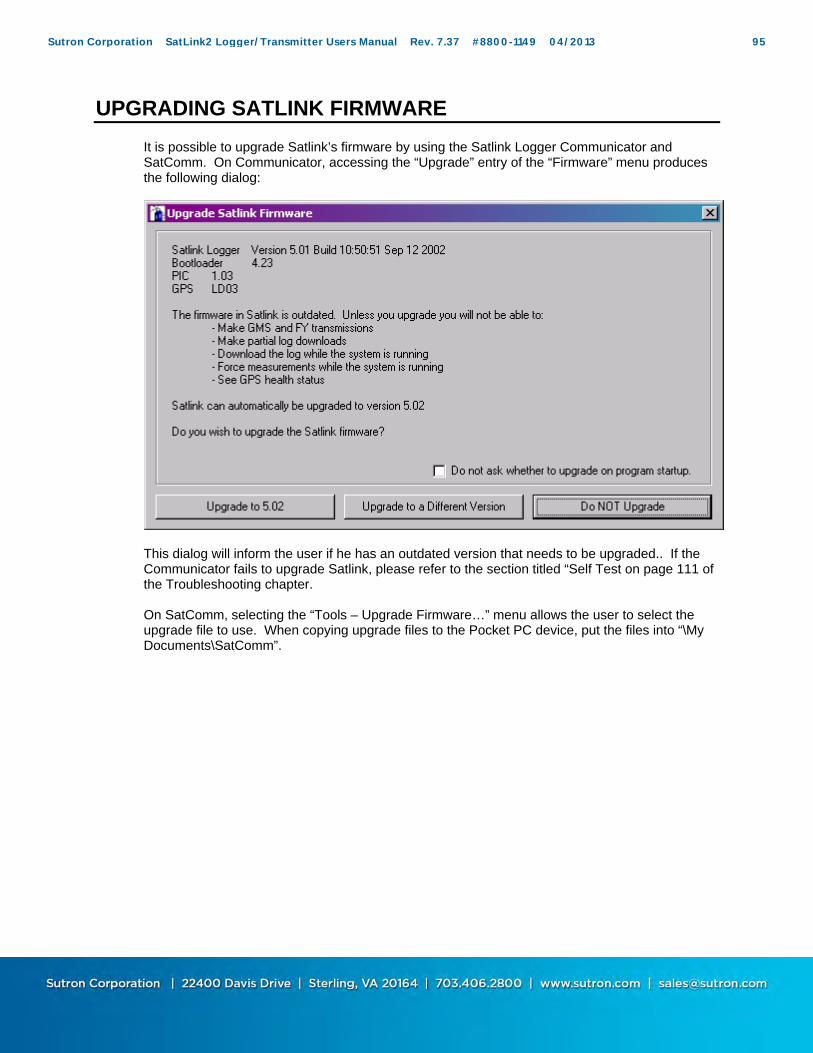
UPGRADING SATLINK FIRMWARE
It is possible to upgrade Satlink’s firmware by using the Satlink Logger Communicator and SatComm. On Communicator, accessing the “Upgrade” entry of the “Firmware” menu produces the following dialog:
This dialog will inform the user if he has an outdated version that needs to be upgraded.. If the Communicator fails to upgrade Satlink, please refer to the section titled “Self Test on page 111 of the Troubleshooting chapter. On SatComm, selecting the “Tools – Upgrade Firmware…” menu allows the user to select the upgrade file to use. When copying upgrade files to the Pocket PC device, put the files into “\My Documents\SatComm”.
Sutron Corporation SatLink2 Logger/Transmitter Users Manual Rev. 7.37 #8800-1149 04/2013 95
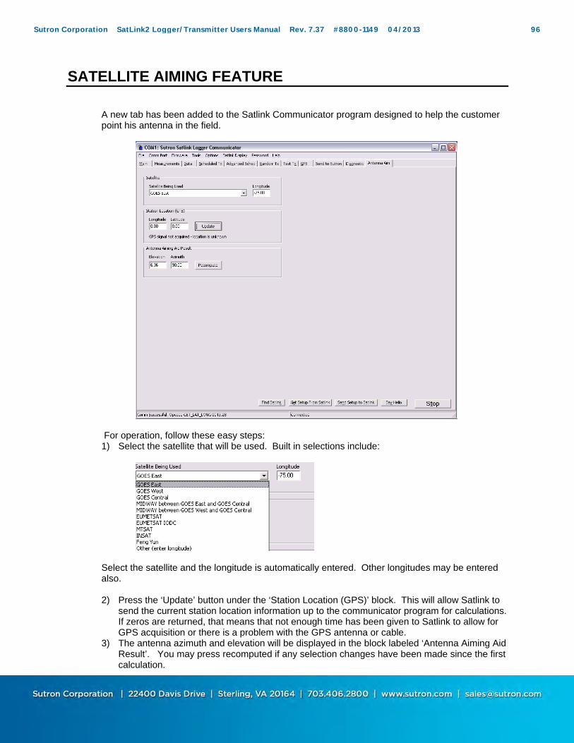
SATELLITE AIMING FEATURE
A new tab has been added to the Satlink Communicator program designed to help the customer point his antenna in the field.
For operation, follow these easy steps: 1) Select the satellite that will be used. Built in selections include:
Select the satellite and the longitude is automatically entered. Other longitudes may be entered also. 2) Press the ‘Update’ button under the ‘Station Location (GPS)’ block. This will allow Satlink to
send the current station location information up to the communicator program for calculations. If zeros are returned, that means that not enough time has been given to Satlink to allow for GPS acquisition or there is a problem with the GPS antenna or cable.
3) The antenna azimuth and elevation will be displayed in the block labeled ‘Antenna Aiming Aid Result’. You may press recomputed if any selection changes have been made since the first calculation.
Sutron Corporation SatLink2 Logger/Transmitter Users Manual Rev. 7.37 #8800-1149 04/2013 96
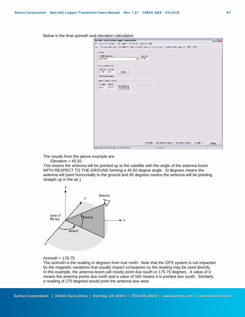
Below is the final azimuth and elevation calculation.
The results from the above example are: Elevation = 45.92 This means the antenna will be pointed up to the satellite with the angle of the antenna boom WITH RESPECT TO THE GROUND forming a 45.92 degree angle. (0 degrees means the antenna will point horizontally to the ground and 90 degrees means the antenna will be pointing straight up in the air.)
Azimuth = 176.75 The azimuth is the reading in degrees from true north. Note that the GPS system is not impacted by the magnetic variations that usually impact compasses so the reading may be used directly. In this example, the antenna boom will mostly point due south or 176.75 degrees. A value of 0 means the antenna points due north and a value of 180 means it is pointed due south. Similarly a reading of 270 degrees would point the antenna due west.
Sutron Corporation SatLink2 Logger/Transmitter Users Manual Rev. 7.37 #8800-1149 04/2013 97
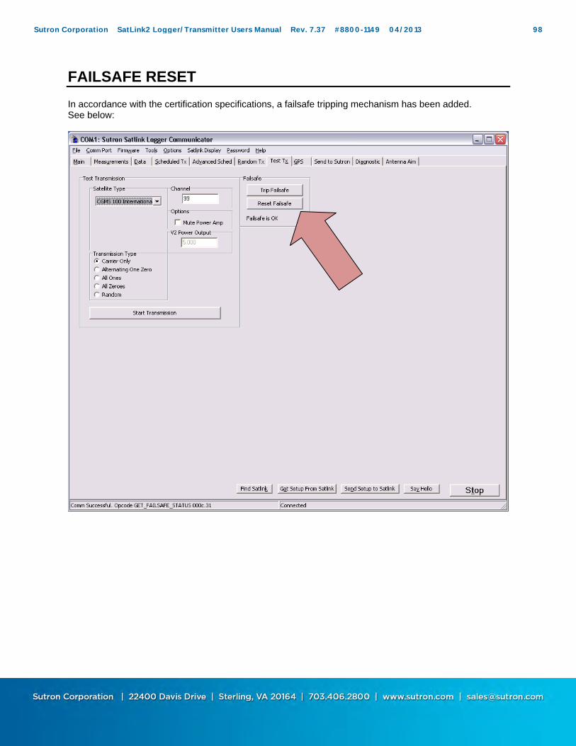
FAILSAFE RESET
In accordance with the certification specifications, a failsafe tripping mechanism has been added. See below:
Sutron Corporation SatLink2 Logger/Transmitter Users Manual Rev. 7.37 #8800-1149 04/2013 98
Chapter 6 Installation
Sutron Corporation SatLink2 Logger/Transmitter Users Manual Rev. 7.37 #8800-1149 04/2013 99
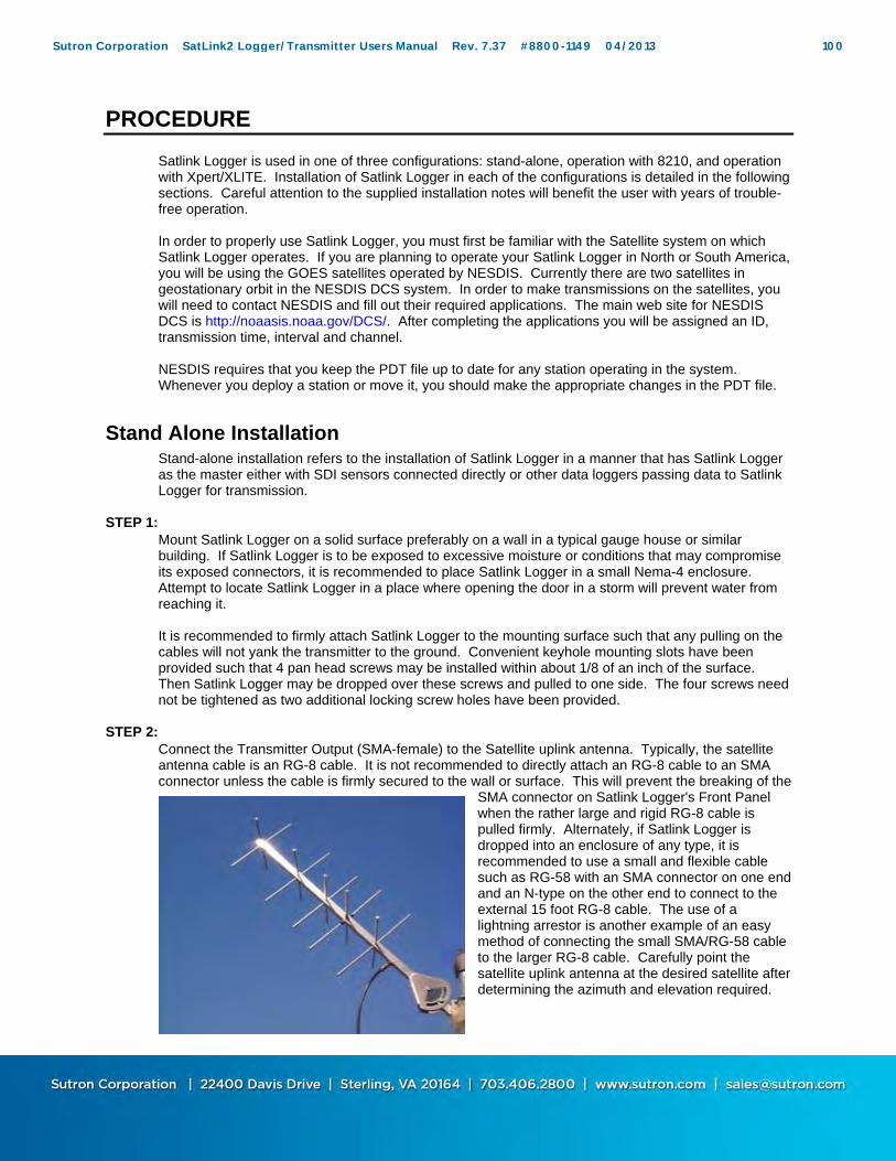
PROCEDURE
Satlink Logger is used in one of three configurations: stand-alone, operation with 8210, and operation with Xpert/XLITE. Installation of Satlink Logger in each of the configurations is detailed in the following sections. Careful attention to the supplied installation notes will benefit the user with years of trouble- free operation. In order to properly use Satlink Logger, you must first be familiar with the Satellite system on which Satlink Logger operates. If you are planning to operate your Satlink Logger in North or South America, you will be using the GOES satellites operated by NESDIS. Currently there are two satellites in geostationary orbit in the NESDIS DCS system. In order to make transmissions on the satellites, you will need to contact NESDIS and fill out their required applications. The main web site for NESDIS DCS is http://noaasis.noaa.gov/DCS/. After completing the applications you will be assigned an ID, transmission time, interval and channel. NESDIS requires that you keep the PDT file up to date for any station operating in the system. Whenever you deploy a station or move it, you should make the appropriate changes in the PDT file.
Stand Alone Installation
Stand-alone installation refers to the installation of Satlink Logger in a manner that has Satlink Logger as the master either with SDI sensors connected directly or other data loggers passing data to Satlink Logger for transmission.
STEP 1: Mount Satlink Logger on a solid surface preferably on a wall in a typical gauge house or similar building. If Satlink Logger is to be exposed to excessive moisture or conditions that may compromise its exposed connectors, it is recommended to place Satlink Logger in a small Nema-4 enclosure. Attempt to locate Satlink Logger in a place where opening the door in a storm will prevent water from reaching it. It is recommended to firmly attach Satlink Logger to the mounting surface such that any pulling on the cables will not yank the transmitter to the ground. Convenient keyhole mounting slots have been provided such that 4 pan head screws may be installed within about 1/8 of an inch of the surface. Then Satlink Logger may be dropped over these screws and pulled to one side. The four screws need not be tightened as two additional locking screw holes have been provided.
STEP 2: Connect the Transmitter Output (SMA-female) to the Satellite uplink antenna. Typically, the satellite antenna cable is an RG-8 cable. It is not recommended to directly attach an RG-8 cable to an SMA connector unless the cable is firmly secured to the wall or surface. This will prevent the breaking of the
SMA connector on Satlink Logger's Front Panel when the rather large and rigid RG-8 cable is pulled firmly. Alternately, if Satlink Logger is dropped into an enclosure of any type, it is recommended to use a small and flexible cable such as RG-58 with an SMA connector on one end and an N-type on the other end to connect to the external 15 foot RG-8 cable. The use of a lightning arrestor is another example of an easy method of connecting the small SMA/RG-58 cable to the larger RG-8 cable. Carefully point the satellite uplink antenna at the desired satellite after determining the azimuth and elevation required.
Sutron Corporation SatLink2 Logger/Transmitter Users Manual Rev. 7.37 #8800-1149 04/2013 100

STEP 3: Connect the GPS antenna to the SMA connector provided on the end panel of Satlink Logger. Be careful not to connect the GPS antenna to the incorrect SMA connector on the end panel of Satlink Logger. Install the antenna with the following items in mind. Place the GPS antenna in the most open space possible. Do not place it directly under anything nor directly beside something. Always attempt to achieve a "full sky" view with the antenna. Place the GPS antenna high up on a pedestal or in a protected location. Flat surfaces may tend to cover with ice and snow more so than elevated locations. Keep away from areas where birds may nest. Placement is very important and great care should be taken in selecting the location. If the surface is metal, the antenna is a magnetic mount that will stick to the surface very easily. If the mount is a non-ferrous material, attach the antenna with double sided tape or a tie down mechanism.
STEP 4:
Connect Satlink Logger's DC power cable to the battery/charger system being careful not to short out the battery or reverse the cable. Note that a fuse is installed in the cable in the event that the power cables are reversed. Upon the reversal of power, a protection circuit will blow the fuse. Always replace with a 3AG size fuse rated at 8 amps (SB).
STEP 5:
Connect SDI-12 sensors to Satlink Logger. If you are using multiple SDI sensors and the address has not been set for the sensors, only connect one of the sensors at this time. Connect a tipping bucket to the Sensor Connector on the front of Satlink (on some older models, this connector is labeled “I2C”). On that connector, use pins 9 (high) and 5 (low) to connect to the tipping bucket.
STEP 6:
Connect the serial port to the PC for testing or to another logger device to feed data into Satlink Logger. If you have already created a setup for the station load it into the Communicator program by opening the file it is stored in. Otherwise, Use the Measurement page to specify how the data is measured, logged and transmitted. Use the Scheduled Tx page to setup the scheduled transmissions and the Random Tx page to setup the random transmissions. When you have finished creating the setup, press "Send Setup to Satlink" to load it into the Satlink Logger.
STEP 7:
While on the Measurement page, you may configure any SDI sensors that need configuration. Use the Send SDI-12… button to send the desired configuration commands to the SDI-12 devices. You will need to refer to the operator's manual for each specific SDI-12 sensor to know which commands to send. You may also send commands to make measurements and operate the SDI-12 sensor. You may also want to force some measurements to make sure the sensors are operating properly. Use the Force button to force Satlink Logger to take a measurement of the sensor selected.
STEP 8: Press the “Start” button at the bottom right of the display. This causes Satlink Logger to begin to use the schedule to make automatic measurements and transmissions.
Sutron Corporation SatLink2 Logger/Transmitter Users Manual Rev. 7.37 #8800-1149 04/2013 101

Go to the Main tab and verify the system status. It should say that the system is running, that measurements are active, and that transmissions are enabled.
STEP 9:
Go to the Data tab and select a measurement that you have set up. Once a measurement has been made (according to the schedule you have made), hit the refresh button to see the data collected by Satlink Logger. You may find out when the soonest measurement is supposed to occur by going to the Main tab.
8210 Internal Installation
8210 with Satlink 2 8210 with Satlink 2 and Speech Modem
STEP 1:
Repeat the same process as the stand-alone version with the following exceptions: If Satlink Logger is not meant to do anything on its own, i.e. independently of the 8210 such as make measurements, it is important to set Satlink Logger to Factory defaults. The serial port is connected to the special db-9 board provided within the 8210. The DC power is provided via the top most of the 3 white power connectors provided on the side panel of the inside of the 8210. The GPS cable will pass through the enclosure and directly connect to Satlink Logger. Plug the opening with the supplied cable gland. A special RF output cable is provided bringing the RF output power over to the side of the 8210 with an N-type connector.
8210 External Installation The 8210 external arrangement is the same as the internal 8210 connections with the following differences: Use a standard DB-9 cable to connect Satlink Logger's serial port to the DB-9 connector provided on the bottom of the 8210. Power Satlink Logger directly to the battery using the provided connectors. Use a short cable to adapt the SMA RF output connector on Satlink Logger to the RG-8 antenna cable.
Sutron Corporation SatLink2 Logger/Transmitter Users Manual Rev. 7.37 #8800-1149 04/2013 102

Xpert Installation The Xpert connection is the same as the 8210 external connection except that the Xpert is used in place of the 8210.
Optional Items In locations with heavy lightning exposure, it is recommended to use a lightning arrestor. Typically, bulkhead mount types are attached to the side of an enclosure or other available surface. Good grounding is essential for proper operation.
Sutron Corporation SatLink2 Logger/Transmitter Users Manual Rev. 7.37 #8800-1149 04/2013 103
Chapter 7 Maintenance and Troubleshooting
Sutron Corporation SatLink2 Logger/Transmitter Users Manual Rev. 7.37 #8800-1149 04/2013 104
TROUBLESHOOTING
Q: How can I troubleshoot my Satlink Logger site? A: Equipment Needed: Bird model 43 Wattmeter (or equivalent) Bird 25 watt element Bird dummy load capable of 25 watts Good RF cable (shorter cables have less loss) A SMA male-to-male Type N adapter
1. Force a transmission, measure, and record output power of transmitter. This is done by connecting the test RF cable to the transmitter and wattmeter, with the dummy load on the output of the wattmeter.
2. Force a transmission, measure, and record output power of transmitter. Now connect the site's RF cable to the wattmeter, with the dummy load on output of the wattmeter. Subtract this value from the value recorded in Step 1. There should be less than a 2 watt loss in the RF cable. If there is more, the cable needs to be replaced/repaired.
3. Now connect the antenna to the output of the wattmeter (you will need the SMA male-to-male Type N adapter or a short cable providing the same adapting capability to do this) leaving the site's RF cable connecting the transmitter and the wattmeter. Force a transmission on your random channel (so that you do not walk on someone else's scheduled transmission). Measure the reflected power of the antenna by turning the wattmeter element so that the arrow faces away from the antenna. There should be less than a 1/2 watt of reflected power. If there is more, the antenna needs to be replaced/repaired.
4. Now connect the wattmeter to the transmitter with the test RF cable. Connect the site's RF cable and antenna to the wattmeter's output. Force a transmission on your random channel, measure the reflected power of the site's RF cable. There should be less than a 1/2 watt loss of reflected power. If there is more, the cable needs to be replaced/repaired.
Part Numbers: 5000-0080 Antenna, YAGI Satellite 5000-0081 Antenna, YAGI Satellite with stainless steel elements 6411-1162-1 Cable Assy, Antenna, 15 ft
Q: Why will my Satlink Logger not turn on? A: When first powered up, the red light on Satlink Logger's front panel should turn on and blink. If no lights turn on, check to make sure power is running to the unit.
1. Are the power cords connected properly? Check Satlink's connection to the power supply for a bad connection.
2. Does the battery have a good charge? 3. Is the fuse on the power cable blown? Satlink Logger requires a 3AG, 8 AMP, slow blow fuse in
order to operate. 4. If power is properly supplied, but the unit still does not turn on, call Customer Service for assistance.
Q: The LED on the front panel blinks, but the Communicator still cannot find Satlink Logger? A: Did the unit boot up properly? See Depot Level Troubleshooting for the boot up sequence.
1. If it booted up properly, the light should blink once every five seconds. If it doesn't do this, contact Customer Service.
2. If the five second heartbeat happens as expected, but the Communicator still cannot find Satlink Logger, check the serial port connections to make sure they are properly connected.
3. Make sure that COMM port is not being used by another program such as HyperTerminal or even another Satlink Logger Communicator. In this case Satlink Logger Communicator will say it cannot open the COMM port.
Sutron Corporation SatLink2 Logger/Transmitter Users Manual Rev. 7.37 #8800-1149 04/2013 105

Q: Why is my sensor not recording data at all? A: Is the most recent data displayed? Press "Refresh Data" on the Data tab to get the latest data.
A: Check to make sure that the measurements are being made 1. Go to the Main tab and press "Get Status." This should display Satlink Logger's current configuration. 2. Is the System running? If the system is stopped press the Start button. 3. Are the measurements active? The status should display which measurements are active. Check to
make sure that the box "Active" is checked for the measurements you want to record. The user can also check this by viewing "Index" on the Data tab. Active measurements have asterisks by them.
4. Is the interval set for the right time? Check that you have the proper interval and time set. The time for the next measurement should be displayed. Note that the red LED on Satlink Logger should blink twice when a measurement is made
Q: Why is Satlink Logger occasionally skipping measurements? A: Considerable effort has gone into making sure Satlink Logger will accurately record measurements.
However, certain scenarios could cause Satlink Logger to miss an occasional measurement. 1. Measurement interval too short – This error is returned when the interval for recording
measurements is too short for the sensors to handle. SDI-12 devices take a certain length of time to make their measurements. Some devices even require several minutes to finish a measurement; so sending a measurement (0M! or 0C!) request too often will cause data to be lost. Multiple non-concurrent measurements (0M!) are made one at a time, so the time required to make all measurements is cumulative. Concurrent measurements commands (0C!) are issued simultaneously, and collected after the non-concurrent measurements. This means that the total time required to make a measurement is either the sum of all non-concurrent measurement times, or the longest concurrent measurement time, whichever is greatest. If the interval is shorter then this total time data will be lost.
2. Missed scheduled measurement – Measurements take some time to make, as described in the previous paragraph. If one or more measurements are scheduled to occur while another previously scheduled measurement is still in process, this error will occur. Depending on several factors, Satlink Logger will try to catch up and make the missed measurements after the first measurement is completed. This will only occur, however, if there is enough time before the next time that missed measurement is to be recorded, so two of the same measurements will not be made one after the other. If Satlink Logger cannot catch up, the data will be logged as "Never Recorded".
3. The exact time that measurements are made can be seen as part of the debug information located on the Diagnostic tab.
Q: Satlink Logger is making measurements correctly, but why am I receiving wrong values? A: Check that the measurement is set up correctly. The quickest way to verify that a measurement is set up
properly is to force a measurement. Does the reading come back as expected? A: There are several different things that could cause Satlink Logger to display the wrong values
1. Is the Quality Flag for the data marked as Bad? Check the sensor to make sure it is properly connected and configured. Make sure that the terminal strip is pinching down on the wires and not the insulation. If the sensor is a SDI-12 device, check if the proper command is being sent to the correct address for the sensor in use.
2. Is the sensor value incorrect? Check to make sure that the measurements’ slope, offset, and for tipping buckets, that the initial tipping bucket count is correct. Also some SDI-12 sensors also have a built-in slope and offset. If this is the case consult the individual sensor's manual for instructions.
Q: The internal/external measurements are fine, but why isn't Satlink Logger transmitting the data? A: Check your settings.
1. Check the Main tab to ensure that the system is running and transmissions are enabled. If transmissions are enabled, the Main tab should also display the time of the next transmission.
Sutron Corporation SatLink2 Logger/Transmitter Users Manual Rev. 7.37 #8800-1149 04/2013 106
2. Is the Failsafe tripped? If the message "FAILSAFE TRIPPED", appears on the Main tab, then the unit cannot transmit until the unit is reset. To reset the failsafe either press the Reset button on Satlink Logger's case, or use the Visual Interface and select "Reset Failsafe" on the Main tab.
3. During the transmission, what does the battery voltage drop to? The battery voltage must not drop below 10.5V DC. If the voltage does drop below 10.5 volts, either the battery needs to be replaced, or it does not have a good charge.
4. What is the output power of the transmitter? It should be 8 watts ± 1 dB for 100/300 baud, 16 watts ± 1dB for 1200 baud. Lower power may cause problems with the signal being received at the satellite. Higher power may cause your signal to "bleed over" into another frequency and overload the transponder, and therefore, is monitored by NESDIS.
5. Make sure the "Include" box on the Measurements tab for each measurement you want to transmit is checked for either/both Scheduled and Random transmissions. So if you have a 15 minute measurement interval and you are transmitting every 4 hours, you would set your "Num vals to Tx" to 16 to transmit all of the collected data for the past 4 hours. If you want to transmit redundant data, you could set your "Num vals to Tx" to 32. All of the collected data for the past 8 hours is then transmitted.
6. Is the station ID set? The factory default is FFFFFFFF, which inhibits transmissions. The user must set a valid ID to allow the transmitter to be enabled.
7. Did you select an invalid channel? Satlink Logger knows not to transmit on channel 100 at the 100/300 assignment. Never set it to this channel, as transmissions will not occur.
8. Is the RS232 cable connected? Check cable for damage, corrosion, etc. 9. Is the GPS antenna connected? Check the connections. Check the cable for damage. Using visual
interface, try to sync to GPS under the GPS tab. Q: Why does the transmission contain M’s or /// in place of data? A: Satlink Logger uses "M" in SHEF and "///" in Binary formatting to indicate a missing measurement. Data is usually missing because the measurements have been made yet. Satlink transmits recently collected data, not logged data. When a Satlink is rebooted, it has no data to transmit. If a transmission is made before all measurements have been made, missing values will be transmitted. Another cause of missing measurements is the coinciding of transmission and measurement schedules. If a measurement is set to be collected at the same time as Satlink is preparing the transmission data, the most recent measurement will be missing. The way to solve this problem is to have the measurement to be made earlier. Setup measurements to be made at least minute before transmissions. This can be easily accomplished by setting the measurement Offset to one minute and checking the ‘Relative to Tx’ setting on the Measurements tab. For example, if 6 values are set to be included in a transmission, and only 4 measurements have been made, Satlink Logger will transmit the 4 available values, and missing data indicators for the other two. Q: Why does Satlink fail the first transmission after bootup? A: Satlinks equipped with a Trimble GPS module require up to 30 minutes to acquire GPS time synchronization after the first power up in a new location. If a Satlink is scheduled to transmit before the GPS has acquired time, that transmission will fail. However, once Satlink acquires that first lock, all the following transmissions will work as normal.
Sutron Corporation SatLink2 Logger/Transmitter Users Manual Rev. 7.37 #8800-1149 04/2013 107

STATUS AND ERROR MESSAGES
Error Messages – Occasionally Satlink Logger will display an error message as part of the Status panel on the Main tab. Some of these messages will indicate the reason why Satlink failed a transmission. Here is a list of messages and how to deal with them:
1. Active measurement has zero interval – Each active measurement's interval must be greater than zero. The interval can be changed on the Measurements tab
2. Already Transmitting – A transmission is currently in progress, so the unit cannot be started.
3. Bad amp temp – If temperature of the final amplifier is too high, the transmission will be aborted. Waiting several minutes for the amplifier to cool down should permit transmissions to resume.
4. Bad forward power – Any failure of the transmitter that would permit too much forward RF power to the antenna will activate a shutdown circuit. The RF power will remain off for the remainder of the message. When the condition no longer exists transmissions will be resumed.
5. Battery Low – The voltage level for Satlink Logger cannot fall below 10.5V during a transmission. Check the charge of the battery.
6. Cannot tune modulator – Prior to each transmission, the DC offsets are automatically adjusted thereby calibrating the transmitter. In the event that the offsets cannot be adjusted, the transmission will be aborted.
7. Error syncing clock to GPS – The GPS signal acquired is too weak to sync the clock with it. Try increasing the "GPS Acquire Time" or repositioning the antenna.
8. Failsafe not reset – The failsafe was tripped prior to transmission. Satlink Logger cannot transmit when the failsafe is tripped.
9. Failsafe tripped – This error indicates that the failsafe was tripped during a transmission. The failsafe is separate from the main circuit and makes certain that the unit does not break transmission regulations. This can be reset on the front panel of Satlink Logger, or on the Main tab of the Communicator.
10. Forced measurement in progress – A user-initiated measurement is already in progress. To cancel the first measurement press "Abort" on the Measurements tab, then continue with the new forced measurement.
11. Frequency discipline failed – Satlink Logger failed to discipline it’s TCXO. 12. GPS failed to acquire time – Satlink could not acquire a GPS signal in the specified
time. Try increasing the "GPS Acquire Time" or repositioning the antenna. 13. Initialization failed – Internal error. If this error persists try resetting to Factory Defaults. 14. Internal timing error – Satlink Logger was unable to finish the preparation of a
transmission before the target time. The transmission is aborted. 15. Invalid channel – Certain satellite types do not support certain channels. Check your
channel and satellite type settings. 16. Invalid satellite type – Same as previous. 17. Loops not locked – A key component of the transmission failed to occur, thus causing
the transmission to abort. 18. Measurement interval too short – Setting the measurement interval shorter than the
time needed by an SDI-12 device to make a measurement causes this error. 19. Missed scheduled measurement – An unfortunate timing conflict has occurred where a
measurement was missed due to another measurement being made. Try adjusting the measurement times so that they are measured simultaneously and not one after another.
20. Modulator not configured – The factory calibration for the unit has been lost. It must be sent back to Sutron for recalibration.
21. PIC comm failure – Internal error. Satlink Logger will take care of this error by itself. 22. Satellite ID not set – The factory default is FFFFFFFF, which inhibits transmissions. The
user must set a valid ID to allow the transmitter to be enabled. 23. SDI-12 comm failure – Satlink Logger has difficulty communicating with the attached
SDI-12 device. Check the connection to the device, and the device's configuration.
Sutron Corporation SatLink2 Logger/Transmitter Users Manual Rev. 7.37 #8800-1149 04/2013 108

24. SDI-12 command empty – A measurement command must be specified for the active measurement. See Appendix D for more information on SDI-12 commands.
25. Software failsafe tripped – Some internal errors may cause the failsafe to trip, such as transmitting within a short time after rebooting. This also prevents Satlink Logger from breaking transmission regulations. This failsafe resets itself.
26. Time way off – When the GPS time sync for a transmission reveals a large time discrepancy, the transmission may be aborted. This commonly occurs during the first transmission after boot up.
27. User aborted Tx – The user has aborted a transmission, usually by stopping the system before a transmission's preparation is finished.
28. Out of heap memory – Indicates errors in the internal workings of the system. 29. Heap crash – Indicates errors in the internal workings of the system. 30. 8400 comm failure – Satlink failed to get data from an 8400 DDR. 31. Cimel comm failure – Satlink failed to get data from a CIMEL data logger. 32. Failed to log-log busy – Satlink failed to log a measurement because the log was being
cleared or downloaded (Satlink will buffer up measurements that need to be logged. Only during an extremely fast measurement schedule will the Satlink fail to log).
33. Autostart failed-invalid setup – When Satlink was booted up, it attempted to start but could not due to an invalid setup.
34. Frequency not disciplined – Satlink failed to compensate for TCXO frequency drift. This error may be caused by GPS failing to acquire satellites.
35. PIC Chip dead – Indicates a fatal hardware error. This is usually accompanied by a “Failsafe Tripped” error. The PIC is responsible for the failsafe operations of the transmitter and Satlink cannot transmit without it.
36. Loop one not locked (Loop two not checked) – Hardware failure in the radio hardware. If it persists, Satlink needs to be sent back to the factory.
37. Loop two not locked (Loop one locked) - Hardware failure in the radio hardware. If it persists, Satlink needs to be sent back to the factory.
38. String heap crash – Internal software error that will cause Satlink to reset itself using the watchdog. Satlink should be able to recover after it reboots and continue running.
39. Automatic gain control failed – Satlink 2 is having trouble outputting the proper RF power. Could be caused by a weak power supply, a bad load on the RF connector (bad antenna), or hardware failure.
40. Runaway code – Unexpected software failure. Satlink should end up being reset by the watchdog, restart and resume operation.
41. Weak battery self shutdown – Satlink tried to transmit, but the power supplied was too weak to sustain transmission. Transmission was aborted part-way.
42. TCXO out of range – Satlink’s internal oscillator used to create the transmission carrier signal has drifted out of spec. Satlink will need to be sent back to the factory for TCXO replacement.
43. This Satlink cannot do analog measurements – Crafty user managed to setup a Satlink Logger that has no analog measurement circuitry to do analog measurements. The analog measurements will fail. In order to do analog measurements, either obtain a Satlink 2 or add Sutron’s SDI-12 AnalogPlus module to Satlink.
44. Analog chip failure – The chip responsible for making analog measurements is not responding in expected ways.
45. User erased log – The user has issued an erase log command. 46. Battery High – Battery voltage exceeded maximum allowed for transmission.
Transmission was aborted. 47. SDI-12 time set failure – Satlink failed to set the time of an SDI-12 device that supports
the XDT command. 48. Missing samples – A measurement that was the average of multiple samples had fewer
samples than expected. 49. Invalid samples - A measurement that was the average of multiple samples had some
invalid samples. The invalid samples were not included in the average. 50. Internal error – Includes other potential errors not included in this list.
Sutron Corporation SatLink2 Logger/Transmitter Users Manual Rev. 7.37 #8800-1149 04/2013 109
Status Descriptions – Satlink Logger performs a variety of tasks, which are displayed in the Status panel on the Main tab. The following lists the possible system statuses:
1. Continuing Random Tx – A Random transmission, which has been delayed by a higher priority transmission will now begin processing.
2. Encoding data for Tx – The encoding is split into two parts, the encoding of the sensor data, and the encoding of the buffer data.
3. Frequency discipline started/completed – A part of the transmission is disciplining the TCXO using the ultra-accurate 1Hz signal from the GPS.
4. GPS satellite acquisition started – The GPS unit is searching for a signal from the satellites, in order to acquire the time and location information.
5. GPS time sync started/succeeded – This occurs periodically while Satlink Logger is running to ensure the accuracy of the GPS time and position. This occurs at boot-up, before each transmission, and after long stretches of time when no sync has been made.
6. GPS use disabled – To re-enable the GPS, reset to factory defaults. 7. Idling – The unit is waiting until the next command is given. 8. Locking loops – Just prior to transmission, Satlink Logger will lock onto the frequency
specified for the transmission. 9. Random Tx preparation started – Signifies the beginning of a Random transmission. 10. Random Tx successfully completed – The Random Transmission process has
finished. 11. Scheduled Tx preparation started – Marks the beginning of a Scheduled Transmission. 12. Scheduled Tx successfully completed – The Scheduled Transmission process is
done. 13. Send to Sutron Tx successfully completed – A transmission has been successfully
sent to Sutron for troubleshooting purposes. 14. Send to Sutron Tx prep started – A transmission is being prepared to be sent to
Sutron. 15. System time changed – This occurs whenever the system clock is adjusted by a
substantial amount. 16. Test Tx preparation started – A test transmission, used for troubleshooting, is being
prepared. 17. Transmission stopped – The transmission, whether successful or not, has been
completed. 18. Transmitting – The desired information is being sent by radio wave to its destination. 19. Waiting for post-Tx quiet time to pass – After each transmission there is a set period
of time that Satlink Logger cannot transmit due to radio transmission regulations. 20. Waiting for TCXO warmup – The TXCO needs a bit of time before it provides a stable
signal. 21. Waiting for Tx time – This state is for when Satlink Logger is waiting for a specific time
to execute one of its commands during a Scheduled Transmission. 22. GPS satellite acquisition started – Satlink powered the GPS module to allow it to acquire
satellite signal.
Sutron Corporation SatLink2 Logger/Transmitter Users Manual Rev. 7.37 #8800-1149 04/2013 110
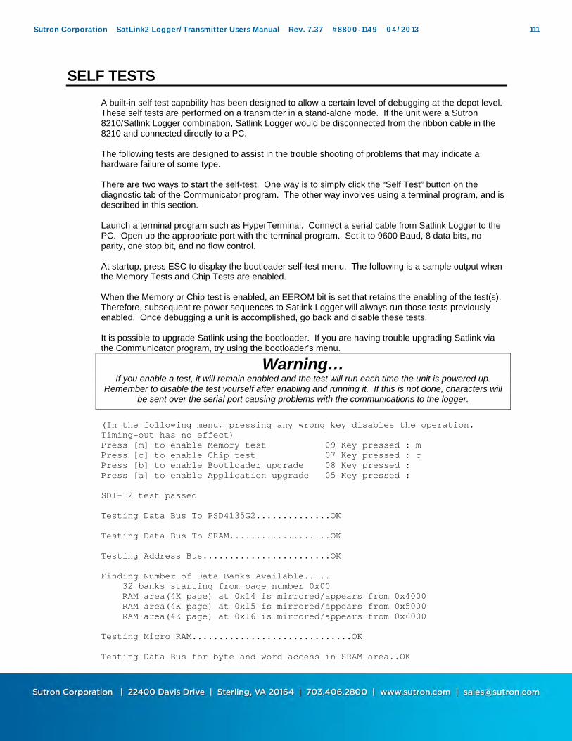
SELF TESTS
A built-in self test capability has been designed to allow a certain level of debugging at the depot level. These self tests are performed on a transmitter in a stand-alone mode. If the unit were a Sutron 8210/Satlink Logger combination, Satlink Logger would be disconnected from the ribbon cable in the 8210 and connected directly to a PC. The following tests are designed to assist in the trouble shooting of problems that may indicate a hardware failure of some type. There are two ways to start the self-test. One way is to simply click the “Self Test” button on the diagnostic tab of the Communicator program. The other way involves using a terminal program, and is described in this section. Launch a terminal program such as HyperTerminal. Connect a serial cable from Satlink Logger to the PC. Open up the appropriate port with the terminal program. Set it to 9600 Baud, 8 data bits, no parity, one stop bit, and no flow control. At startup, press ESC to display the bootloader self-test menu. The following is a sample output when the Memory Tests and Chip Tests are enabled. When the Memory or Chip test is enabled, an EEROM bit is set that retains the enabling of the test(s). Therefore, subsequent re-power sequences to Satlink Logger will always run those tests previously enabled. Once debugging a unit is accomplished, go back and disable these tests. It is possible to upgrade Satlink using the bootloader. If you are having trouble upgrading Satlink via the Communicator program, try using the bootloader’s menu.
Warning… If you enable a test, it will remain enabled and the test will run each time the unit is powered up.
Remember to disable the test yourself after enabling and running it. If this is not done, characters will be sent over the serial port causing problems with the communications to the logger.
(In the following menu, pressing any wrong key disables the operation. Timing-out has no effect) Press [m] to enable Memory test 09 Key pressed : m Press [c] to enable Chip test 07 Key pressed : c Press [b] to enable Bootloader upgrade 08 Key pressed : Press [a] to enable Application upgrade 05 Key pressed : SDI-12 test passed Testing Data Bus To PSD4135G2..............OK Testing Data Bus To SRAM...................OK Testing Address Bus........................OK Finding Number of Data Banks Available..... 32 banks starting from page number 0x00 RAM area(4K page) at 0x14 is mirrored/appears from 0x4000 RAM area(4K page) at 0x15 is mirrored/appears from 0x5000 RAM area(4K page) at 0x16 is mirrored/appears from 0x6000 Testing Micro RAM..............................OK Testing Data Bus for byte and word access in SRAM area..OK
Sutron Corporation SatLink2 Logger/Transmitter Users Manual Rev. 7.37 #8800-1149 04/2013 111

Testing Data Bus for byte and word access in PSD area...OK Testing PSD4135 RAM from 0x2000 to 0x3fff in unbanked space....OK Testing SRAM from 0x4000 to 0x4fff in unbanked space....OK Testing SRAM from 0x7000 to 0x7fff on DataPage 0x00....OK Testing SRAM from 0x7000 to 0x7fff on DataPage 0x01....OK Testing SRAM from 0x7000 to 0x7fff on DataPage 0x02....OK Testing SRAM from 0x7000 to 0x7fff on DataPage 0x03....OK Testing SRAM from 0x7000 to 0x7fff on DataPage 0x04....OK Testing SRAM from 0x7000 to 0x7fff on DataPage 0x05....OK Testing SRAM from 0x7000 to 0x7fff on DataPage 0x06....OK Testing SRAM from 0x7000 to 0x7fff on DataPage 0x07....OK Testing SRAM from 0x7000 to 0x7fff on DataPage 0x08....OK Testing SRAM from 0x7000 to 0x7fff on DataPage 0x09....OK Testing SRAM from 0x7000 to 0x7fff on DataPage 0x0a....OK Testing SRAM from 0x7000 to 0x7fff on DataPage 0x0b....OK Testing SRAM from 0x7000 to 0x7fff on DataPage 0x0c....OK Testing SRAM from 0x7000 to 0x7fff on DataPage 0x0d....OK Testing SRAM from 0x7000 to 0x7fff on DataPage 0x0e....OK Testing SRAM from 0x7000 to 0x7fff on DataPage 0x0f....OK Testing SRAM from 0x7000 to 0x7fff on DataPage 0x10....OK Testing SRAM from 0x7000 to 0x7fff on DataPage 0x11....OK Testing SRAM from 0x7000 to 0x7fff on DataPage 0x12....OK Testing SRAM from 0x7000 to 0x7fff on DataPage 0x13....OK Testing SRAM from 0x7000 to 0x7fff on DataPage 0x17....OK Testing SRAM from 0x7000 to 0x7fff on DataPage 0x18....OK Testing SRAM from 0x7000 to 0x7fff on DataPage 0x19....OK Testing SRAM from 0x7000 to 0x7fff on DataPage 0x1a....OK Testing SRAM from 0x7000 to 0x7fff on DataPage 0x1b....OK Testing SRAM from 0x7000 to 0x7fff on DataPage 0x1c....OK Testing SRAM from 0x7000 to 0x7fff on DataPage 0x1d....OK Testing SRAM from 0x7000 to 0x7fff on DataPage 0x1e....OK Testing SRAM from 0x7000 to 0x7fff on DataPage 0x1f....OK Reading PSD4135 Memory information......... Boot Flash: 32 K Bytes Main Flash: 512 K Bytes SRAM : 8 K Bytes Turning ON switched 12volts,hence green LED.. Battery voltage Measured = 11.53 Volts.....OK Testing Modulator register # 0x01...OK Testing Modulator register # 0x02...OK Testing Modulator register # 0x03...OK Testing Modulator register # 0x04...OK Testing Modulator register # 0x05...OK Testing Modulator register # 0x06...OK Testing Modulator register # 0x07...OK Testing Modulator register # 0x0a...OK Testing Modulator register # 0x0c...OK Testing Modulator register # 0x0d...OK Testing for Symbol rate: 100, Symbol Rate Measured: 100.......OK Testing for Symbol rate: 300, Symbol Rate Measured: 300.......OK Testing for Symbol rate: 1200, Symbol Rate Measured: 1200.......OK Turning OFF switched 12volts, hence green LED Testing DS1306 Real Time Clock......... Testing if DS1306 RTC is ticking....OK This verifies SPI communication also. Testing DS1306 RTC Alarm 0..........OK
Sutron Corporation SatLink2 Logger/Transmitter Users Manual Rev. 7.37 #8800-1149 04/2013 112

Testing DS1306 RTC Alarm 1..........OK Searching GPS module...................Connected on SCI-2 port $Version BOOT 1 $Version 1.3.4M00283LD02 END OF POWER-ON SELF-TEST
Sutron Corporation SatLink2 Logger/Transmitter Users Manual Rev. 7.37 #8800-1149 04/2013 113

Chapter 8 Command Line
Sutron Corporation SatLink2 Logger/Transmitter Users Manual Rev. 7.37 #8800-1149 04/2013 114

SATLINK COMMAND LINE
One of the communications protocols supported by Satlink is called command line. It allows limited access to Satlink via the RS232 interface using a terminal program such as HyperTerminal. This chapter provides details on the command line. Currently, command line is useful for downloading logged data.
Set up Setup RS232 for 9600 baud, no parity, 8 data bits, 1 stop bit, and turn on hardware handshaking.
Wake up Asserting RTS wakes Satlink up. Once the RTS is asserted, wait at least 500ms before sending data (will automatically happen if using a modem). Satlink will assert CTS in reply. If you are using HyperTerminal, just open the port (Call menu, Call).
Set up and wake up are no different for command line then they are for Satlink Protocol.
Initiating command line To start command line mode, send carriage return or line feed (or both) Hex values for those bytes are 0x0D and 0x0A. If using HyperTerminal or a similar program, simply press ENTER. Satlink will respond with a prompt > (that is the greater than sign, hex value 0x3E)
Issuing commands Follow ALL commands with a carriage return or line feed (or both). Satlink will echo the typed data (unless Machine mode is used – see below). Satlink’s echo is capitalized. Try typing HI. Satlink will reply with Hello.
Commands supported BATT shows battery details DOWNLOAD or LOG will transfer the log from the unit Type "LOG HELP" for more details HI will have Satlink reply with Hello. REBOOT restarts the unit STATUS or S shows current status VER will show software version information
Machine mode Precede commands with a ! for a concise reply and no echo. For example, type !LOG to download the log. Satlink will immediately start the log download. Machine mode is meant for machine to machine interaction – i.e. connecting you data logger or automatic dialer to Satlink
Downloading the log Data logged by Satlink is available to download to via command line. The command “LOG” command will start the log download. There are optional parameters that alter what data is downloaded: “LOG NY” with no parameters will download since last. “LOG ALL NY” gets whole log. “LOG X NY” gets X last days ("LOG 3" gets last 3 days worth of data) “LOG timeStart NY” gets data since provided date “LOG timeStart timeEnd NY” gets data between provided dates time can be YYYY/MM/DD HH:MM:SS or YYYY/MM/DD or HH:MM:SS e.g. "LOG 12:00:00 13:00:00 NY"
Sutron Corporation SatLink2 Logger/Transmitter Users Manual Rev. 7.37 #8800-1149 04/2013 115

e.g. "LOG 2006/01/20 12:00:00 2006/01/21 12:00:00 NY" “LOG HELP” Shows details on how to use the download command. What is the NY for? Sutron's Monitor family of products use YModem transfer to download the log via command line. For conformity to an existing standard, NY is used to indicate that YModem is not to be used. Satlink does NOT use YModem for the log download. The logged data is output as an ASCII stream. Data output can be paused by pressing the space key (0x30), resumed by sending the enter key (0x0D or 0x0A or both), and aborted by pressing escape (0x1B). Additionally, removing the RTS signal will pause the download. If RTS does not re-assert after 30 seconds, the connection will be dropped. After Satlink has given all the data it has for the specified time period, it will send three carriage return new line sequences (0x0D0A0D0A0D0A).
Log format The logged data will be in Sutron CSV format: mm/dd/yyyy,hh:mm:ss,label,data[,units,qual][,label,data[,units,qual]] e.g. 05/29/2009,21:53:39,snsr,-0.128000,,G G is the quality (stands for Good). The two commas after the value are a placeholder for units (units are not supported by Satlink).
Terminating the connection If a download is not in progress, dropping RTS will terminate the connection as will sending the “BYE” “QUIT” or “EXIT” commands.
Sutron Corporation SatLink2 Logger/Transmitter Users Manual Rev. 7.37 #8800-1149 04/2013 116

Session example The data below is a capture of a command line session with Satlink. The data in CAPS is sent by user (and echoed by Satlink). > is the command prompt. DevOne is the station name. G is the quality (stands for Good). The two commas after the value are a placeholder for units (units are not supported by Satlink).
>HI Hello. >STATUS SATLINK: Version 6.40 Build 13:51:20 Sep 29 2009 DevOne System time 2009/10/06 03:23:27 Booted at 2009/10/06 03:22:21 BATT 13.37V >LOG Downloading since last download During the log download Press SPACE to pause (ENTER to unpause) Press ESC to abort Press any key (or wait) to start download 05/29/2009,21:53:39,snsr,-0.128000,,G 05/29/2009,21:53:40,snsr,-0.128000,,G 05/29/2009,21:53:41,snsr,-0.128000,,G 05/29/2009,21:53:42,snsr,-0.128000,,G 05/29/2009,21:53:43,snsr,-0.128000,,G 05/29/2009,21:53:44,snsr,-0.128000,,G 05/29/2009,21:53:45,snsr,-0.128000,,G 05/29/2009,21:53:46,snsr,-0.128000,,G 05/29/2009,21:53:47,snsr,-0.128000,,G 05/29/2009,21:53:48,snsr,-0.128000,,G 05/29/2009,21:53:49,snsr,-0.128000,,G 05/29/2009,21:53:50,snsr,-0.128000,,G 05/29/2009,21:53:51,snsr,-0.128000,,G 05/29/2009,21:53:52,snsr,-0.128000,,G 05/29/2009,21:53:53,snsr,-0.128000,,G 05/29/2009,21:53:54,snsr,-0.128000,,G 05/29/2009,21:53:55,snsr,-0.128000,,G 05/29/2009,21:53:56,snsr,-0.128000,,G 05/29/2009,21:53:57,snsr,-0.128000,,G 05/29/2009,21:53:58,snsr,-0.128000,,G 05/29/2009,21:53:59,snsr,-0.128000,,G Download Complete >BYE Bye. Be sure to disconnect cable.
Sutron Corporation SatLink2 Logger/Transmitter Users Manual Rev. 7.37 #8800-1149 04/2013 117

Appendices
Sutron Corporation SatLink2 Logger/Transmitter Users Manual Rev. 7.37 #8800-1149 04/2013 118

APPENDIX A: OPERATION WITH SUTRON 8210
This is the addendum to the 8210 manual for version 6.1. It provides user information regarding the added features to the 8210 logger to properly set up and control Sutron’s Satlink Logger transmitter. It explains the added features only. See the 8210 operators manual chapter 4-21 for further GOES setup information.
Summary of Features/Changes The 8210-SL14-1 has been designed to operate nearly identically to the 8210-5014-1. the following is a summary of the features of the 8210-SL14-1and changes you will see from older versions.
1. The 8210-SL14-1 runs Version 6.1 or later of the operating system. This version supports the new Satlink Logger transmitter as well as all the other communications modes for the 8210. The only functions not in 6.1 that are in 4.A are some of the SSP monitoring functions.
2. The system supports scheduled and random transmissions at rates of 100, 300 and 1200 BPS. The selection of the baud rate is done using a simple menu selection.
3. Satlink Logger's transmitter has a built-in GPS receiver to receive time. The 8210 will synchronize its clock to Satlink Logger before each transmission. You should never need to set the time again on an 8210-SL14. Satlink Logger syncs its time to GPS periodically, before each transmission, and when power is first applied.
4. The 8210 can read in setups from units running version 4.X. If you read in an older setup, you will still need to select the GOES baud rate for the transmission in the GOES Setup menu.
5. Important: Even though version 6.1 is compatible with 4.X setups, you should set up each new configuration on the bench before deploying it in the field.
6. Satlink Logger works independently of the 8210 for its timed transmissions. When recording is turned ON, the 8210 sends to Satlink Logger the desired schedule and transmitter settings. About 30 seconds before a timed transmission, the 8210 will synchronize its clock to Satlink Logger, format the data and send it to Satlink Logger. At the required transmission time, Satlink Logger sends the data. If for some reason Satlink Logger does not get data from the 8210, Satlink Logger will still go ahead and transmit. The message will be “Data Buffer Empty”.
7. Satlink Logger works a bit differently for the random transmissions. Random transmissions are initiated by the 8210 based on the settings for RN Rate and RA Rate. When the 8210 wants to send a random transmission it again syncs its clock to Satlink Logger, then formats the data and sends it to Satlink Logger with a command to transmit randomly. Satlink Logger will then transmit the data, usually within a 2 minute window.
8. If the 8210 cannot communicate with Satlink Logger, the message “NOCOM “will be displayed for the recording status. Usually this means that the cable connecting Satlink Logger to the 8210 is not connected. A similar NOCOM message will be displayed in the Inspect System/Display Status screen.
9. The Inspect System/Display status screen has a few changes. The display now reports Satlink Logger good and bad transmission counts. That is because Satlink Logger keeps its own counts of transmissions. The time of last transmission is now the time that the 8210 formatted its data for transmission. As explained above, this can be 30 seconds before the time of the timed transmission.
10. The 8210 supports the “Send Timed” and “Send Random” test transmissions. These transmissions should be done only into a dummy load, and not over the satellite. When you select either of these test transmissions, the 8210 will send the command to Satlink Logger. Satlink Logger will then go through its pre-transmission sequence to acquire time, frequency and then transmit. The actual transmission may not happen until up to 2 minutes from when the test transmission was started.
11. The transmission formats from the 8210-SL14-1 are supposed to be identical to the transmission formats of the 8210-5014-1,however, there were some changes made to the formatting routines, so be sure and bench test a unit before going to the field to install it.
The following sections give some details to the operation of the 8210-SL14-1.
Sutron Corporation SatLink2 Logger/Transmitter Users Manual Rev. 7.37 #8800-1149 04/2013 119
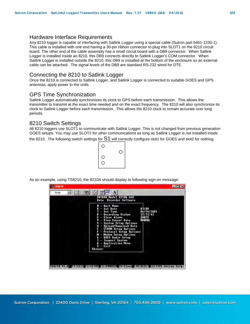
Hardware Interface Requirements Any 8210 logger is capable of interfacing with Satlink Logger using a special cable (Sutron part 6461-1230-1). This cable is installed with one end having a 30-pin ribbon connector to plug into SLOT1 on the 8210 circuit board. The other end of the cable assembly has a small circuit board with a DB9 connector. When Satlink Logger is installed inside an 8210, this DB9 connects directly to Satlink Logger's COM connector. When Satlink Logger is installed outside the 8210, this DB9 is installed at the bottom of the enclosure so an external cable can be attached. The signal levels of the DB9 are standard RS-232 wired for DTE.
Connecting the 8210 to Satlink Logger Once the 8210 is connected to Satlink Logger, and Satlink Logger is connected to suitable GOES and GPS antennas, apply power to the units.
GPS Time Synchronization Satlink Logger automatically synchronizes its clock to GPS before each transmission. This allows the transmitter to transmit at the exact time needed and on the exact frequency. The 8210 will also synchronize its clock to Satlink Logger before each transmission. This allows the 8210 clock to remain accurate over long periods.
8210 Switch Settings All 8210 loggers use SLOT1 to communicate with Satlink Logger. This is not changed from previous generation GOES setups. You may use SLOT2 for other communications as long as Satlink Logger is not installed inside
the 8210. The following switch settings for S1 will correctly configure slot1 for GOES and slot2 for nothing. As an example, using TS8210, the 8210A should display to following sign-on message:
Sutron Corporation SatLink2 Logger/Transmitter Users Manual Rev. 7.37 #8800-1149 04/2013 120
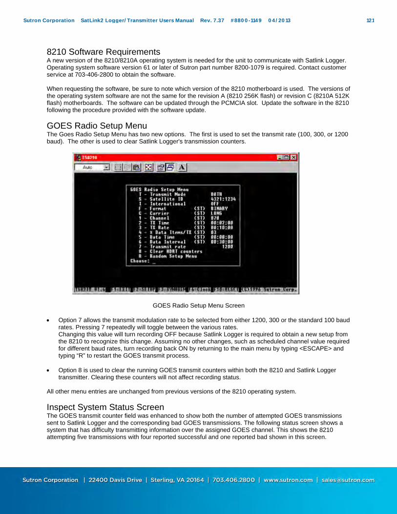
8210 Software Requirements A new version of the 8210/8210A operating system is needed for the unit to communicate with Satlink Logger. Operating system software version 61 or later of Sutron part number 8200-1079 is required. Contact customer service at 703-406-2800 to obtain the software. When requesting the software, be sure to note which version of the 8210 motherboard is used. The versions of the operating system software are not the same for the revision A (8210 256K flash) or revision C (8210A 512K flash) motherboards. The software can be updated through the PCMCIA slot. Update the software in the 8210 following the procedure provided with the software update.
GOES Radio Setup Menu The Goes Radio Setup Menu has two new options. The first is used to set the transmit rate (100, 300, or 1200 baud). The other is used to clear Satlink Logger's transmission counters.
GOES Radio Setup Menu Screen
Option 7 allows the transmit modulation rate to be selected from either 1200, 300 or the standard 100 baud
rates. Pressing 7 repeatedly will toggle between the various rates. Changing this value will turn recording OFF because Satlink Logger is required to obtain a new setup from the 8210 to recognize this change. Assuming no other changes, such as scheduled channel value required for different baud rates, turn recording back ON by returning to the main menu by typing <ESCAPE> and typing “R” to restart the GOES transmit process.
Option 8 is used to clear the running GOES transmit counters within both the 8210 and Satlink Logger
transmitter. Clearing these counters will not affect recording status. All other menu entries are unchanged from previous versions of the 8210 operating system.
Inspect System Status Screen The GOES transmit counter field was enhanced to show both the number of attempted GOES transmissions sent to Satlink Logger and the corresponding bad GOES transmissions. The following status screen shows a system that has difficulty transmitting information over the assigned GOES channel. This shows the 8210 attempting five transmissions with four reported successful and one reported bad shown in this screen.
Sutron Corporation SatLink2 Logger/Transmitter Users Manual Rev. 7.37 #8800-1149 04/2013 121
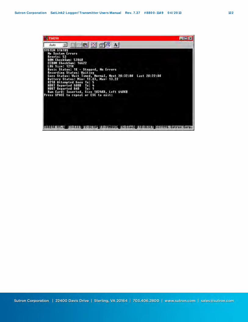
Sutron Corporation SatLink2 Logger/Transmitter Users Manual Rev. 7.37 #8800-1149 04/2013 122

Front Panel GOES Radio Setup Changes Two new menu selections were added to the front panel. GoesRate <value>
This entry allows the operator to change the GOES transmit modulation rate between either 1200, 300 or 100 baud rates. Pressing the <SET> key repeatedly will toggle between the various rates. Changing this value will turn recording OFF because Satlink Logger is required to obtain a new setup from the 8210 to recognize this change. Assuming no other changes, such as scheduled channel value required for different baud rates, turn recording back ON by using the arrows to move to the recording menu entry and pressing <SET> to restart the GOES transmit process.
Send Clock
This entry allows the operator to transfer the 8210 time setting to Satlink Logger. Make sure GMT time is set in the 8210 before transferring the time. Press the <SET> key to do this.
Front Panel Inspect System Menu Changes Within the inspect system menu, the GOES RADIO TEST menu will only perform the following actions.
Send test data over the scheduled channel
This option will send test data over the channel assigned for scheduled transmissions. Send test data over the random channel
This option will send test data over the channel assigned for random transmissions. Notes/Issues: 1. When the 8210 displays the recording status, it will send a request of the status to Satlink Logger. If
the 8210 does not get a reply, “NOCOM” will be displayed. 2. Note that the 8210 will wake up 30 seconds before the time of a transmission in order to format the
data and send it to Satlink Logger. 3. GOES setup errors means one of the following: no sensor in group being transmitted, less than 4
minutes between transmissions. 4. In the status message, time of last transmission is the time that the 8210 formatted the data (29 to 30
seconds before the actual transmission was made).
Sutron Corporation SatLink2 Logger/Transmitter Users Manual Rev. 7.37 #8800-1149 04/2013 123
APPENDIX B: OPERATION WITH SUTRON XPERT
The operation of Satlink Logger with an Xpert is fully documented in the Xpert Operation and Maintenance Manual (part number 8800-1127). This section gives a brief overview of the functions:
Control Panel Satlink Logger's branch in the control panel is used to manage the details of the setup for both Scheduled and Random transmissions. The main branch sets the Satellite ID, Comm port (Xpert connection to Satlink Logger) and whether or not the Xpert will alter settings in Satlink Logger. The Scheduled and Random branches in the control panel allow the setup of Scheduled and Random transmissions. This includes the setup of the channel, format, transmission type, transmission time, transmission intervals and so forth. The Scheduled Test and Random Test branches in the control panel allow you to view the current message that would be sent by Satlink Logger, make test transmissions, and view the transmitter status.
Setup Telemetry blocks are used in the setup in order to include data in Scheduled and Random transmissions as well as trigger random transmissions. When you want a particular value included in a scheduled transmission, you must connect the value to a Scheduled block. The properties of this block allow you to specify data used by the formatter in order to include the data in the transmission. Data are included in random transmissions by connecting the value to a Random block. Finally, you control the values that trigger random transmissions by connecting the value to a Random Group block. The properties of this block set the type of checks to run on the data in order to generate random transmissions including hi alarm, low alarm, rate of change alarm and the corresponding levels and limits. The details of these blocks and the control panel properties are found in the Xpert Operator and Maintenance Manual.
Sutron Corporation SatLink2 Logger/Transmitter Users Manual Rev. 7.37 #8800-1149 04/2013 124
APPENDIX D: MORE ABOUT SDI-12
Overview SDI-12 is a standard for interfacing data recorders with microprocessor based sensors. SDI-12 stands for serial data interface at 1200 baud. SDI-12 is intended for applications with the following requirements:
Battery powered operation with minimal current drain Low system cost Use of a single data recorder with multiple sensors on one cable Up to 200 feet of cable between the sensor and a data recorder
SDI-12 has the following advantages:
It defines a standard way for a data recorder and sensor to communicate. Unique and complex self-calibration algorithms can be done in the sensor itself. Sensors can be interchanged without reprogramming the data recorder with calibration or other
information. Power is supplied to sensors through the interface. The use of a standard serial interface eliminates significant complexity in the design of the data
recorder. Low cost, small sensors can be designed with SDI-12 compatibility. SDI-12 data recorders interface with a variety of sensors. SDI-12 sensors interface with a variety of data recorders. Personnel trained in SDI-12 will have skills to work with a variety of SDI-12 data recorders and
sensors. SDI-12 is used in water resource research and management, industry, government, and agriculture. For example, the U.S. Geological Survey uses over 4000 SDI-12 sensors in its data collection networks. SDI-12 sensors are available that measure the following:
bridge scour conductivity dissolved oxygen distance groundwater level petroleum hydrocarbons in water pH pressure redox (ORP) tank level temperature tide and sea state turbidity water velocity weight of snow and ice on a snow pillow wind speed and direction
Sutron also offers general purpose interfaces for making analog and digital measurements via SDI-12. For more information on SDI-12, go to www.sdi-12.org.
Wiring SDI allows you to connect up to 10 sensors with as many as many as 9 parameters each. The interface is implemented using three wires: data, ground, and +12V. The ground conductor of the SDI interface line should be large enough to keep the voltage drop between the data recorder and the sensor to less than 0.5 volts
Sutron Corporation SatLink2 Logger/Transmitter Users Manual Rev. 7.37 #8800-1149 04/2013 125
during the maximum sensor current drain. Failure to observe this specification will cause bad communications and/or bad data. The maximum current used on the +12V line should not exceed 2 amps at any time.
Connector The connector type is not part of the SDI specification. On Satlink Logger, the connector is labeled: G (Ground), + (12V) and D (Data). Multiple sensors can be connected to these connections.
SETUP of SDI sensors Each SDI-12 sensor has an address from 0 to 9. This address differentiates one sensor from another. As they are shipped, they are almost always set to address zero (0). If/when you are interfacing more than one sensor to Satlink Logger you must set each sensor to a unique address. This is normally done by setting dipswitches on the sensor or by software commands. Failure to set unique addresses for each sensor will result in failure of the communications interface (i.e. no data logged). Consult the sensor manufacturers data for information on your particular sensor(s). Note that Satlink Logger Communicator provides a means to set up the SDI-12 sensors via its Measurements tab, “Send SDI-12 Command”.
Useful SDI commands Resetting the address by software (some sensors) is normally done by sending the aAb! command. (a A b !, where a is the current address of the sensor you want to change and b is the address you want to change to, e.g. 0A5! changes the address of sensor 0 to address 5.) Another useful SDI-12 command is the aI! (where a is the address of the sensor, e.g. 3I! for sensor at address 3) command. 4I! will return an identification string from the sensor at address 4 which includes the SDI version number, vendor's name, sensor model number, sensor version number, and serial number. This is a quick way to see if the sensor is responding properly. A way to verify data collection (manual data collection) is to issue the aM! command. For example 7M! would collect data from the sensor at address 7. The sensor will respond with a 5-digit code -- the first digit is the address, the next 3 digits are the required time for measurement in seconds, and the last digit is the number of data values returned. Wait for the number of seconds. Then issue the aD0! (address, D, zero, !) the sensor should respond with one or more data values. You may issue further aD1! … aDn! till you get all of the data. If the SDI sensor is version 1.3 (which can be found out by sending the ?I! command; the version is returned as the second and third characters of the response), then make sure to use the CRC measurement commands. These commands work just like normal measurement commands, except that they use an error checking mechanism that minimizes errors. So, instead of 0M!, use 0MC!. Instead of 0M1!, use 0MC1!. This will ensure reliable SDI communication.
Sutron Corporation SatLink2 Logger/Transmitter Users Manual Rev. 7.37 #8800-1149 04/2013 126
APPENDIX E: DATA TRANSMISSION FORMATS
Satlink Logger can be configured to transmit the data in several different formats: 1) Random Transmission Pseudobinary format 2) Scheduled Transmission Pseudobinary 3) Scheduled Transmission SHEF format 4) Scheduled Transmission SHEFFIX format
RANDOM TRANSMISSION PSEUDOBINARY DATA FORMAT This format is used when Satlink Logger makes a random or alarm transmission. The format of the transmission data is:
<GROUP-ID> <OFFSET> <MEASUREMENT1-DATA(1)> <MEASUREMENT1-DATA(2)> ... <MEASUREMENT1-DATA(N)> <MEASUREMENT2-DATA(1)> <MEASUREMENT2-DATA(2)> ... <MEASUREMENT2-DATA(N)> <MEASUREMENT3-DATA(1)> <MEASUREMENT3-DATA(2)> ... <MEASUREMENT3-DATA(N)> <EXTERNAL DATA> <COUNTER> <BATTLOAD> <LAT/LONG> where:
GROUP ID The GROUP ID is a “2” for all random transmissions.
OFFSET OFFSET is a 1-byte binary encoded number indicating the number of
minutes ago the most recent data was recorded. Note that the number of minutes is calculated about 15 seconds prior to transmission.
MEASUREMENT DATA
Measurement data collected by Satlink Logger: this data contains only those measurements set up to be included in the random transmission. The data values are 3 byte binary encoded signed numbers allowing a range of: -131072 to +131071. The actual 6-bit binary encoded format is described later. The value transmitted is taken directly from the 32 value measurement buffer in Satlink Logger. The value transmitted will be value * 10^RightDigits. The string "///" will be sent if the data was never measured or was erased. The number of values sent for each measurement is set separately for each measurement in the Random Transmissions, Num values to Tx field. Note that this is different from the 8210 where the num values to Tx was the same for each sensor. As a result, Satlink Logger sends all the required values for one sensor (most recent first) before proceeding to the next measurement. In the 8210, values were interleaved.
EXTERNALDATA
This is data given to Satlink Logger by a device through the RS-232 port. This data is untouched by Satlink Logger. It gets transmitted in the same way it was received.
Sutron Corporation SatLink2 Logger/Transmitter Users Manual Rev. 7.37 #8800-1149 04/2013 127

LAT/LONG This is an optional field; it will be included only if “Append Lat/Long” is selected for random transmissions. LAT/LONG can be decoded into D:M:S format by converting the binary values to decimal and applying the following formula:
Degrees latitude = 64 * ( 1st-byte AND 63 ) + ( 2nd-Byte AND 63) 90 Minutes latitude = 3rd-byte AND 63 Seconds latitude = 4th-byte AND 63 Degrees longitude = 64 * ( 5th -byte AND 63) + ( 6th -Byte AND 63) 180 Minutes longitude = 7th-byte AND 63 Seconds longitude = 8th-byte AND 63
For example BAAODAXe would be decoded as Lat 39o 1' 15" Long 77o 24' 37" Fractional seconds are scientifically rounded. The hemisphere is NOT encoded. One cannot tell whether the station is North or South, East or West via pseudobinary encoding.
COUNTER COUNTER is a 2 byte binary encoded number which indicates the transmission number and increments after every transmission. The number will be between 0 and 4095.
BATTLOAD BATTLOAD is a 1 byte binary encoded number representing the battery voltage of Satlink Logger under load during the last transmission. If the battery reading is zero, then that is the first transmission since bootup. The range of the number will be -32 to +31 and can be converted to volts by multiplying by 0.234 and adding 10.6 allowing a range of 3.1 to 18.1 volts.
EXAMPLE: Here is a message with three active measurements; each one is set to include two readings. The random buffer contains the string "EXT". This string was given by an external device through the RS-232 port. 2@@Gt@Gs@Sx@Sr@@i@@iEXTBAAODAXe@GI ||| | | | | | | | | |
||| | | | | | | | | +- Battery Voltage ||| | | | | | | | +--- Random Counter ||| | | | | | | +----------- Latitude/Longitude (optional) ||| | | | | | +-------------- External Data ||| | | | | +----------------- Temp #2 ||| | | | +-------------------- Temp #1 ||| | | +----------------------- Precip #2 ||| | +-------------------------- Precip #1 ||| +----------------------------- Stage #2 ||+-------------------------------- Stage #1 |+--------------------------------- Delta Time +---------------------------------- Group ID = 2
Sutron Corporation SatLink2 Logger/Transmitter Users Manual Rev. 7.37 #8800-1149 04/2013 128
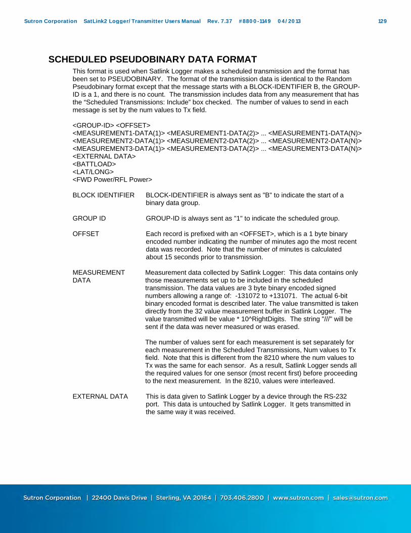
SCHEDULED PSEUDOBINARY DATA FORMAT This format is used when Satlink Logger makes a scheduled transmission and the format has been set to PSEUDOBINARY. The format of the transmission data is identical to the Random Pseudobinary format except that the message starts with a BLOCK-IDENTIFIER B, the GROUP-ID is a 1, and there is no count. The transmission includes data from any measurement that has the “Scheduled Transmissions: Include” box checked. The number of values to send in each message is set by the num values to Tx field.
<GROUP-ID> <OFFSET> <MEASUREMENT1-DATA(1)> <MEASUREMENT1-DATA(2)> ... <MEASUREMENT1-DATA(N)> <MEASUREMENT2-DATA(1)> <MEASUREMENT2-DATA(2)> ... <MEASUREMENT2-DATA(N)> <MEASUREMENT3-DATA(1)> <MEASUREMENT3-DATA(2)> ... <MEASUREMENT3-DATA(N)> <EXTERNAL DATA> <BATTLOAD> <LAT/LONG> <FWD Power/RFL Power>
BLOCK IDENTIFIER BLOCK-IDENTIFIER is always sent as "B" to indicate the start of a
binary data group.
GROUP ID GROUP-ID is always sent as "1" to indicate the scheduled group.
OFFSET Each record is prefixed with an <OFFSET>, which is a 1 byte binary encoded number indicating the number of minutes ago the most recent data was recorded. Note that the number of minutes is calculated about 15 seconds prior to transmission.
MEASUREMENT DATA
Measurement data collected by Satlink Logger: This data contains only those measurements set up to be included in the scheduled transmission. The data values are 3 byte binary encoded signed numbers allowing a range of: -131072 to +131071. The actual 6-bit binary encoded format is described later. The value transmitted is taken directly from the 32 value measurement buffer in Satlink Logger. The value transmitted will be value * 10^RightDigits. The string "///" will be sent if the data was never measured or was erased. The number of values sent for each measurement is set separately for each measurement in the Scheduled Transmissions, Num values to Tx field. Note that this is different from the 8210 where the num values to Tx was the same for each sensor. As a result, Satlink Logger sends all the required values for one sensor (most recent first) before proceeding to the next measurement. In the 8210, values were interleaved.
EXTERNAL DATA This is data given to Satlink Logger by a device through the RS-232
port. This data is untouched by Satlink Logger. It gets transmitted in the same way it was received.
Sutron Corporation SatLink2 Logger/Transmitter Users Manual Rev. 7.37 #8800-1149 04/2013 129
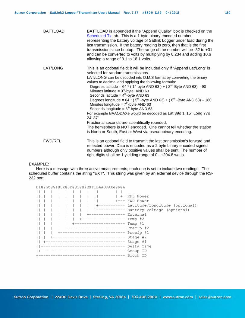
BATTLOAD BATTLOAD is appended if the "Append Quality" box is checked on the Scheduled Tx tab. This is a 1 byte binary encoded number representing the battery voltage of Satlink Logger under load during the last transmission. If the battery reading is zero, then that is the first transmission since bootup. The range of the number will be -32 to +31 and can be converted to volts by multiplying by 0.234 and adding 10.6 allowing a range of 3.1 to 18.1 volts.
LAT/LONG This is an optional field; it will be included only if “Append Lat/Long” is selected for random transmissions. LAT/LONG can be decoded into D:M:S format by converting the binary values to decimal and applying the following formula:
Degrees latitude = 64 * ( 1st-byte AND 63 ) + ( 2nd-Byte AND 63) 90 Minutes latitude = 3rd-byte AND 63 Seconds latitude = 4th-byte AND 63 Degrees longitude = 64 * ( 5th -byte AND 63) + ( 6th -Byte AND 63) 180 Minutes longitude = 7th-byte AND 63 Seconds longitude = 8th-byte AND 63
For example BAAODAXe would be decoded as Lat 39o 1' 15" Long 77o 24' 37" Fractional seconds are scientifically rounded. The hemisphere is NOT encoded. One cannot tell whether the station is North or South, East or West via pseudobinary encoding.
FWD/RFL This is an optional field to transmit the last transmission's forward and reflected power. Data is encoded as a 2 byte binary encoded signed numbers although only positive values shall be sent. The number of right digits shall be 1 yielding range of 0 - +204.8 watts.
EXAMPLE: Here is a message with three active measurements; each one is set to include two readings. The scheduled buffer contains the string "EXT". This string was given by an external device through the RS-232 port.
B1@@Gt@Gs@Sx@Sr@@i@@iEXTIBAAODAXe@R@A
|||| | | | | | | || | | |||| | | | | | | || | +- RFL Power |||| | | | | | | || +--- FWD Power |||| | | | | | | |+----------- Latitude/Longitude (optional)
|||| | | | | | | +------------ Battery Voltage (optional) |||| | | | | | +--------------- External |||| | | | | +------------------ Temp #2 |||| | | | +--------------------- Temp #1 |||| | | +------------------------ Precip #2 |||| | +--------------------------- Precip #1 |||| +------------------------------ Stage #2 |||+--------------------------------- Stage #1 ||+---------------------------------- Delta Time |+----------------------------------- Group ID +------------------------------------ Block ID
Sutron Corporation SatLink2 Logger/Transmitter Users Manual Rev. 7.37 #8800-1149 04/2013 130

SCHEDULED SHEF DATA FORMAT This format is used when Satlink Logger makes a scheduled transmission and the format has been set to SHEF. The format of the transmission data is: ":" <LABEL1> <OFFSET> "#"<INTERVAL> <DATA1> <DATA1> ... <DATA1)> ":" <LABEL2> <OFFSET> "#"<INTERVAL> <DATA2> <DATA2> ... <DATA2> ... ":" <LABEL(N)> <OFFSET> "#"<INTERVAL> <DATA(N)> <DATA(N)> ... <DATA(N)> ":" <EXTERNAL DATA> ":BATTLOAD 0 " <BATTLOAD> <LAT/LONG>
LABEL This is the Label entered in Satlink Logger in the Measurements:Settings:Label field. The Label can be a SHEF two character parameter code such as HF for gauge height or PC for cumulative precipitation or it can be any string you enter. Refer to http://noaasis.noaa.gov/DCS/htmfiles/schefcodes.html for a list of SHEF codes commonly used.
OFFSET Each record is prefixed with an <OFFSET>, which is an ASCII number indicating the number of minutes ago the most recent data was recorded. Note that the number of minutes is calculated about 15 seconds prior to transmission.
INTERVAL INTERVAL indicates how often the measurement was made.
MESURE-MENT DATA
This is data collected by Satlink Logger through measurements. Only those measurements with the Scheduled Transmissions Include box checked are included in the transmission. Like the binary formats, the SHEF format groups all the related data from one measurement. The data is transmitted in ASCII with sign and decimal point (if needed). If a data value has not yet been recorded (or has been erased) the letter "M" for missing data will be sent. The most recent data is always sent first. The number of values sent for each measurement is set on a measurement by measurement basis.
EXTERNAL-DATA
This is data given to Satlink Logger by a device through the RS-232 port. This data is untouched by Satlink Logger. It gets transmitted in the same way it was received.
BATTLOAD BATTLOAD is appended if the "Append Quality" box is checked on the Scheduled Tx tab. <BATTLOAD> represents the battery voltage of Satlink Logger under load during the last transmission. If the battery reading is zero, then that is the first transmission since bootup.
LAT/LONG This is an optional field; it will be included only if “Append Lat/Long” is selected for random transmissions. The Lat/Long information will be user readable. For example, N39O1'18.48"W77O24'36.91" means a latitude of North 39 degrees, 1 minute, 18.48 seconds and longitude of W 77 degrees, 24 minutes, 36.91 seconds.
Sutron Corporation SatLink2 Logger/Transmitter Users Manual Rev. 7.37 #8800-1149 04/2013 131
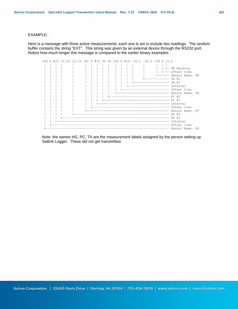
EXAMPLE: Here is a message with three active measurements; each one is set to include two readings. The random buffer contains the string "EXT". This string was given by an external device through the RS232 port. Notice how much longer this message is compared to the earlier binary examples.
:HG 0 #15 10.20 10.15 :PC 0 #15 50 49 :TA 0 #15 -22.1 -22.0 :VB 0 12.2 | | | | | | | | | | | | | | | | | | | | | | | | | | | | | | | | | | | +- VB Reading | | | | | | | | | | | | | | | | + -- Offset time | | | | | | | | | | | | | | | +------ Sensor Name, VB | | | | | | | | | | | | | | +------------- TA #2 | | | | | | | | | | | | | +------------------- TA #1 | | | | | | | | | | | | +---------------------- Interval | | | | | | | | | | | +------------------------- Offset time | | | | | | | | | | +---------------------------- Sensor Name, TA | | | | | | | | | +-------------------------------- PC #2 | | | | | | | | +----------------------------------- PC #1 | | | | | | | +-------------------------------------- Interval | | | | | | +----------------------------------------- Offset time | | | | | +-------------------------------------------- Sensor Name, PC | | | | +--------------------------------------------------- HG #2 | | | +--------------------------------------------------------- HG #1 | | +------------------------------------------------------------ Interval | +--------------------------------------------------------------- Offset time +------------------------------------------------------------------ Sensor Name, HG
Note: the names HG, PC, TA are the measurement labels assigned by the person setting up Satlink Logger. These did not get transmitted.
Sutron Corporation SatLink2 Logger/Transmitter Users Manual Rev. 7.37 #8800-1149 04/2013 132

SIX-BIT BINARY ENCODED FORMAT The six bit binary format is used to encode numbers into displayable ASCII characters. Notice that fractional numbers cannot be represented, so for instance a battery voltage of 13.04 volts set up with 2 right digits will be sent as 1304. A 1 byte encoded number can range from -32 to +31. A 2 byte encoded number can range from -2048 to +2047 A 3 byte encoded number can range from -131072 to +131071 Binary encoded numbers are always sent most significant bytes first. The number itself is broken down into 6-bit digits, and each digit is placed in one byte of data. The number 64 (ASCII "@") is added to each digit to make it fall within the range of displayable ASCII characters. The only exception is that 127 (ASCII <DEL>) is sent as 63 (ASCII "?") Example 1. Encoding the number 10 in 1 byte:
Since 10 will fit in 6-bits we only have to add 64 which would yield 74. So the number 10 would appear as ASCII 74 or the letter "J".
Example 2. Encoding the number 12345 in 3 bytes:
First we have to convert 12345 into binary in 6-bit pieces: 12345 (base 10) = 11 000000 111001 (base 2) Now we can convert each piece back to base 10: 11 000000 111001 (base 2) = 3, 0, 57 Finally, we add 64 to each piece and convert to ASCII: 67, 64, 121 = ASCII "C@y"
Example 3. Encoding the number -12345 in 3 bytes: First we have to convert -12345 into two's complement 18-bit binary: -12345 (base 10) = 111100 111111 000111 (base 2) Now we can convert each piece back to base 10: 111100 111111 000111 (base 2) = 60, 63, 7 Finally, we add 64 to each piece and convert to ASCII (since the second piece is 63 we leave it alone): 124, 63, 71 = ASCII "|?G"
Example 4. Decoding the 3 byte string "@SW":
This is just like encoding except we follow the steps backward. First we convert all the characters to ASCII decimal codes: ASCII "@SW" = 64, 83, 87 Now we subtract 64 from each piece and convert to 6-bit binary: 0, 19, 23 = 000000 010011 010111 Finally, we combine all the bits to form one 18-bit two’s complement number and convert to base 10: 000000010011010111 = 1239
Sutron Corporation SatLink2 Logger/Transmitter Users Manual Rev. 7.37 #8800-1149 04/2013 133

ASCII COLUMN FORMAT The ASCII Column format is another means of encoding transmission data. A message formatted with this method would look like this:
<CRLF> Meas1_Data(1) Meas2_Data(1) ... MeasN_Data(1)<CRLF> Meas1_Data(2) Meas2_Data(2) ... MeasN_Data(2)<CRLF> Meas1_Data(n) Meas2_Data(n) ... MeasN_Data(n)<CRLF>
<CRLF> is a carriage return, line feed Meas1_Data()..MeasN_Data are the data from the active measurements included in the
transmission. All the data on one line are for the same time. A space separates the values. The newest
data is sent first. (n) is the number of values included in the transmission as set by the user. The format for any value is ASCII with the right digits set by the user. No decimal point is shown if the value is zero. Add a minus sign in front of the value if the value is negative. There are no leading zeroes. If the value is missing, two forward slashes are transmitted instead //.
A typical message will appear as follows:
41.79 60.99 12.99 12.43 .20 8.08 7.1 195.2 41.79 60.99 12.99 12.43 1.20 8.08 7.1 195.2 41.79 60.99 12.99 12.43 -2.20 8.08 7.1 195.2
Normally the DCP will be set up so all the sensors are collected at uniform times. If this is not the case, the formatter will still work but will have varying amounts of data on each line (each time) based on whatever sensors are collected at each time. This will produce confusing results if the additional sensors are collected at an interval of the other sensors. The results should be OK if the additional sensors are collected at a time separate time.
Sutron Corporation SatLink2 Logger/Transmitter Users Manual Rev. 7.37 #8800-1149 04/2013 134
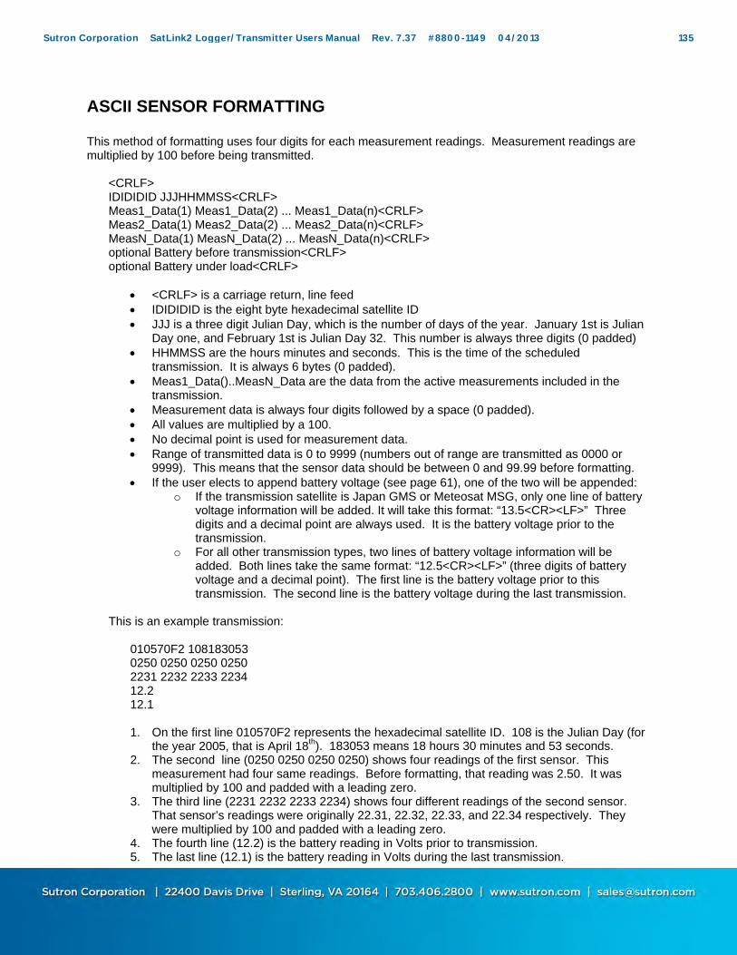
ASCII SENSOR FORMATTING This method of formatting uses four digits for each measurement readings. Measurement readings are multiplied by 100 before being transmitted.
<CRLF> IDIDIDID JJJHHMMSS<CRLF> Meas1_Data(1) Meas1_Data(2) ... Meas1_Data(n)<CRLF> Meas2_Data(1) Meas2_Data(2) ... Meas2_Data(n)<CRLF> MeasN_Data(1) MeasN_Data(2) ... MeasN_Data(n)<CRLF> optional Battery before transmission<CRLF> optional Battery under load<CRLF>
<CRLF> is a carriage return, line feed IDIDIDID is the eight byte hexadecimal satellite ID JJJ is a three digit Julian Day, which is the number of days of the year. January 1st is Julian
Day one, and February 1st is Julian Day 32. This number is always three digits (0 padded) HHMMSS are the hours minutes and seconds. This is the time of the scheduled
transmission. It is always 6 bytes (0 padded). Meas1_Data()..MeasN_Data are the data from the active measurements included in the
transmission. Measurement data is always four digits followed by a space (0 padded). All values are multiplied by a 100. No decimal point is used for measurement data. Range of transmitted data is 0 to 9999 (numbers out of range are transmitted as 0000 or
9999). This means that the sensor data should be between 0 and 99.99 before formatting. If the user elects to append battery voltage (see page 61), one of the two will be appended:
o If the transmission satellite is Japan GMS or Meteosat MSG, only one line of battery voltage information will be added. It will take this format: “13.5<CR><LF>” Three digits and a decimal point are always used. It is the battery voltage prior to the transmission.
o For all other transmission types, two lines of battery voltage information will be added. Both lines take the same format: “12.5<CR><LF>” (three digits of battery voltage and a decimal point). The first line is the battery voltage prior to this transmission. The second line is the battery voltage during the last transmission.
This is an example transmission:
010570F2 108183053 0250 0250 0250 0250 2231 2232 2233 2234 12.2 12.1
1. On the first line 010570F2 represents the hexadecimal satellite ID. 108 is the Julian Day (for
the year 2005, that is April 18th). 183053 means 18 hours 30 minutes and 53 seconds. 2. The second line (0250 0250 0250 0250) shows four readings of the first sensor. This
measurement had four same readings. Before formatting, that reading was 2.50. It was multiplied by 100 and padded with a leading zero.
3. The third line (2231 2232 2233 2234) shows four different readings of the second sensor. That sensor’s readings were originally 22.31, 22.32, 22.33, and 22.34 respectively. They were multiplied by 100 and padded with a leading zero.
4. The fourth line (12.2) is the battery reading in Volts prior to transmission. 5. The last line (12.1) is the battery reading in Volts during the last transmission.
Sutron Corporation SatLink2 Logger/Transmitter Users Manual Rev. 7.37 #8800-1149 04/2013 135
DATA RECEIVED THROUGH DAPS Once data transmitted by Satlink is retrieved, it will have information added on by the NESDIS satellite receiver system. This information was gathered from the “User Interface Manual (UIM) Version 1.1 for the GOES Data Collection System Automatic Processing System (DAPS)”. Here is an example of a message sent by Satlink and received by the DAPS system: 010570F207141162408G40-2NN195EFF00062 SATLINK DATA BUFFER EMPTY Alive TIME 2007/05/21 12:23:54 SATLINK DATA BUFFER EMPTY Alive TIME 2007/05/21 12:23:54 is data sent by Satlink. All the preceding bytes constitute the header added by DAPS. Here is an explanation of the header. The first six bytes 010570F2 are the hexadecimal satellite ID. This is the same as the ID that
Satlink is setup with. It is sometimes referred to as the address. 07 is the year. 07 means 2007. 141 is a three digit julian day of the year. January 1st is Julian Day one, and February 1st is
Julian Day 32. This number is always three digits (0 padded) 162408 is the time of day. 16:24:08. 16 is 4 PM military time, 24 is the number of minutes
and 08 the number of seconds. G is the Failure Code 1. It can be
o G - Good message o ? - Message received with parity errors o W - Message received on wrong channel o D - Message received on multiple channels (duplicate) o A - Message received with address error(s) (correctable) o T - Message received late/early (time error) o U - Unexpected message o M - Missing message o N - PDT entry for this platform is not complete
40 is EIRP or received signal strength (implied EIRP, assuming that the pilot is a +47 dBm reference). Signal strength is output as two ASCII digits ranging between 32 and 57 (decimal). The nominal operating range is 44 to 49 dBm.
-2 is the Frequency Offset. The first byte is an ASCII plus (+) or minus (-) sign, the second byte is an ASCII number zero (0) through nine (9) or the ASCII character "A". The number indicates the amount in increments of 50 Hz. The character "A" represents 500 Hz which is the worst case frequency error that the DAMS units can acquire. The nominal operating range for frequency offset is +250 Hz (+5).
N is the Modulation Index. It can be o N for normal (desired) o L for low o H for high
N is the Data Quality. It can be o N (Normal, error rate better than 1 X 10⁻⁶) o F (Fair, error rate between 1 X 10⁻⁴ and 1 X 10⁻⁶) o P (Poor, error rate worse than 1 X 10⁻⁴)
195 is the transmission channel E is the spacecraft. It can be E for east or W for west. FF is the uplink carrier status 00062 means that 62 bytes of non-header data were received There is a space after 62 and before SATLINK. It is the quality flag:
“ (quote) 0x22 Clock updated since last TX (space) 0x20 Clock not updated since last TX b 0x62 Clock updated, Pseudo Binary ` 0x60 Clock not updated, Pseudo Binary B 0x42 Clock updated, BINARY @ 0x40 Clock not updated, BINARY
Sutron Corporation SatLink2 Logger/Transmitter Users Manual Rev. 7.37 #8800-1149 04/2013 136

APPENDIX F: VERSION HISTORY
Dated April 2013 Satlink 2 Version 7.37
Enhancements: Added new equation function: PULSE12 which controls Switched 12V output
Dated Aug 2012 Satlink 2 Version 7.24
Enhancements: Added support for SDI-12 continuous measurements (aR0! ... aR9!)
Bug fixes: A negative Local Time Offset may cause Satlink to miss transmissions for the length of
the offset. Dated May 2012 Satlink 2 Version 7.23
Enhancements: Added GOES 1200 V2 Support Added option to append forward and reflected power to scheduled pseudobinary
transmission Bug fixes:
Fixed V2 Satlink PIC COM errors
Dated Nov 2011 Satlink 2 Version 7.20, Communicator Version 7.20
Enhancements: Improved V2 Satlink Transmission timing in absence of GPS Added support for certain newer models of tipping buckets with 30ms closure switch
times. Bug fixes:
Fixed Communicator 'floating point error' Fixed comm port not opening in Modem window Battery voltage cutoff limits added to Communicator. Diagnostic value $FpvCar will no longer be logged with each transmission (bug affected
7.07 only) Wrong starting time used when formatting sensor data (bug affected 7.07 only)
Dated April 2011 Satlink 2 Version 7.07, Communicator Version 7.07
Enhancements: GOES V2 Support Window length redefined Added display of available log space Added antenna aiming tool Added user entered cutoff voltages Added user selectable warmup on SDI-12 type sensors
Bug fixes: Placing a slash / in the station name breaks log download
Dated September 2009 Satlink 2 Version 6.40, Communicator Version 3.44
Enhancements: Log download via Hyperterm
Sutron Corporation SatLink2 Logger/Transmitter Users Manual Rev. 7.37 #8800-1149 04/2013 137
Sutron Standard CSV log format added Added DATE and TIME to equation
Bug fixes: Rounding of negative numbers (pseduobinary tx format) Switched 12V never turns off with averaging Modify allowable drift rate in frequency discipline results
Dated March 2009 Satlink 2 Version 6.36, Bootloader 6.01, Communicator Version 3.41
Enhancements: Satlink 2 G312-1B Support Changed 'BATTLOAD' to 'BL' If forward power is less than 1W, transmission is considered bad UTC default is -15
Bug fixes: Slash in station name breaks log download Setup export fails ASCII data appearing in 100BPS random messages Communicator checkbox ‘Do not ask whether to upgrade…’ now works
Dated November 2008 Satlink 2 Version 6.36 and Communicator Version 3.39 and Display SD 3.38 and Display 2.08
Bug fixes: Upgrades Trimble GPS to fix future UTC offset issues
Enhancements: Voice functionality completed
Dated August 2008 Satlink 2 Version 6.32 and Communicator Version 3.37 and Display 3.37
Enhancements: Preliminary voice functionality added (requires SD w/ internal modem) Failsafe can be reset via display
Bug fixes: Trimble GPS changed UTC offset to -15 too soon Setting a Local Time Offset causes high current Equation cannot handle exponents of negative numbers Confusing advanced transmission settings removed
Dated February 2008 Satlink 2 Version 6.31 and Communicator Version 3.31
Enhancements: New functions added to equation processor (POLY, STEINHART) New opcodes added to access status data Allow a means to erase equations from drop down list
Bug fixes: Equation space used by measurement that previously used equations
Dated February 2008 Satlink 2 Version 6.30 and Communicator Version 3.30 and Display Version 3.25
Enhancements: Total number of measurements increased from 10 to 16 Sampling/Averaging enhanced by adding an “Averaging Time” time field. Live Data Poll feature added to Communicator Communicator can adjust baud rate for log downloads to user’s liking
Bug fixes: SHEF formatting of multiple min/max values corrected to use multiple entries
Sutron Corporation SatLink2 Logger/Transmitter Users Manual Rev. 7.37 #8800-1149 04/2013 138

Communicator no longer writes the .ini file to the Windows directory. It uses the local directory for all users.
Communicator could not talk to Display if Auto-Update was enabled. Dated August 2007 Satlink1 5.14 Satlink 2 Version 6.24 and Communicator Version 3.24
Bug fixes: INSAT transmissions were always at the top of the second. Fixed to be anywhere during
the second. Random pseudobinary transmission offset byte was always ?. Satlink may cause Sutron Sdi Shaft Encoder rotation to change to clockwise (bug since
6.22 only) Dated March 2007 Satlink 1 Version 5.12 and Communicator Version 3.23
Bug fixes: Handling incorrect time from the GPS. Communictor would not close if it could not write to the .ini file.
Dated March 2007 Satlink 2 Version 6.22 and Communicator Version 3.22 and Display Version 3.21
Enhancements: Remove measurement cutoff voltage. Enhance time setting via SDI-12.
Bug fixes: Handling incorrect time from the GPS. Frequency discipline from the future (GPS malfunction). Advanced settings binary data format and interleaver do not work together. Satlink Display fails to find internal modem.
Dated October 2006 Satlink 2 Version 6.21 and Communicator Version 3.21
Enhancements: Added additional frequency discipline filter.
Bug fixes: Satlink could stop measuring (bug in versions 6.15 to 6.20) Multiple concurrent SDI-12 measurements on same sensor were not treated as
concurrent.
Dated July 2006 Satlink 2 Version 6.17 and Communicator Version 3.19
Enhancements: Added Tipping Bucket Rate Measurement Type Synchronizes clock with SDI devices such as the Sutron SDR and Sutron CF Bubbler Add FRACT, INT, ABS functions to equation processing Communicator can open .sls file on startup (via drag and drop, command line, or .sls file
association) Bug fixes:
Local Time offset above 9 hours works properly now Satlink did not acknowledge Cimel after receiving transmission data Analog SW+12V failure (introduced in 6.10) System time was garbled on computers running Windows with the Chinese language Disabling/enabling one equation sometimes disables all equations
Sutron Corporation SatLink2 Logger/Transmitter Users Manual Rev. 7.37 #8800-1149 04/2013 139
Communicator did not properly remember entered SDI-12 commands in Send SDI-12 Command window
Dated January 2006 Satlink 2 Version 6.13 and Communicator Version 3.17
Enhancements: Minimum and maximum processing added Satlink password protection added Additional log format added Voltage cutoff limits changed. Satlink will not measure if voltage is too low. Satlink Temperature measurement type added. Identical measurements shared (if the same sensor type is setup in two different measurements, only one reading is made and used by both measurements). Meteosat MSG maximum transmission length changed from one minute to four minutes.
Bug fixes: Satlink used to take responses from any SDI-12 address. Fixed rare bug that would cause Satlink log download to fail immediately after it started. Checking firmware version from the Scheduled Tx tab could cause Communicator to
show SHEF instead of Pseudobinary sensor data formatting.
Dated August 2005 Satlink 2 Version 6.10
Enhancements: Analog measurements accuracy improved. Analog measurements sampling speed improved for 0-5V and ratiometric type readings. A new type of analog measurement (bridge) added. SDI sampling speed increased by as much as two seconds.
Bug fixes: Satlink used to take responses from any SDI-12 address. Forcing concurrent SDI-12 measurements did not work. Extremely long GOES 1200 messages (with more than 8K of data) could have been
scrambled near the end. SHEF encoding delta-time was off by 1 minute. Forced transmissions with ASCII Sensor format used to have a time of 0. Trimble GPS UTC offset fix.
Communicator Version 3.14.02 Enhancements:
New analog measurement type added: bridge. Bug fixes:
Buffer Control Window : Append Data to Satlink's Buffer does not work (bug only in 3.13)
Dated April 2005 Satlink 2 Version 6.09
Enhancements: Two new transmission formats for sensor data collected by Satlink: ASCII Column and
ASCII Sensor. GMS satellite transmission have an additional end of transmission character (an equals
sign = ) ARGOS satellite transmission power adjusted. NDBC 40 Watt mode power readings have been corrected (Satlink must be calibrated to
read correctly) NDBC 40 Watt mode is controlled via switched 12V on the analog sensor connector. Satlink will not transmit if the supply voltage is too high.
Bug fixes:
Sutron Corporation SatLink2 Logger/Transmitter Users Manual Rev. 7.37 #8800-1149 04/2013 140

SDI-12 Communications with certain devices were failing. Satlink's response time was increased.
Communicator Version 3.13.04 Enhancements:
New transmission sensor format modes added: ASCII Column and ASCII Sensor. Unavailable transmission options grayed out based on satellite type and format. This
makes it obvious what settings will not have any effect on specific satellite types. Calibration of Satlink output power for Sutron personnel improved. INSAT power control
removed. Dated December 2004 Satlink 2 Version 6.08
Enhancements: ARGOS and SCD satellite support Feng Yun satellite support NDBC 40W mode support Improvements to satellite transmission frequency stability.
Communicator Version 3.12.19 Enhancements:
Modem dialing improved. Satlink supports ARGOS and SCD satellite types. NDBC 40W Mode support. Support for Satlink display Various minor fixes and improvements.
Bug Fixes: Occasional log download failures fixed (bug would manifest with the YModem Progress
dialog showing no progress and no log being downloaded). CmdListAutoSave.cmd file created only when necessary. Two Communicator programs can download logs from two Satlinks at the same time.
Dated September 2004 Satlink 2 Version 6.07
Enhancements: INSAT satellite support added for Satlink2. Modem and Bluetooth support added by loosening the timing restraints on
communication. Satlink can now keep local rather than UTC time through the local time offset control. Measurements now have default labels. Support for Satlink Display (allows for measurement calibration while Satlink is running).
Bug Fixes: Tipping bucket input no longer makes superfluous counts on a noisy input. This only
affects tipping buckets connected directly to Satlink, not those connected to 8210, 9210 or other data loggers giving data to Satlink.
When restarted, Satlink would not display the last measurement reading to the user. This would not affect transmissions or logged data, only data displayed to the user in the measurement tab of the Communicator program.
Communicator Version 3.11.02 Enhancements:
Communicator can talk to Satlink via Modem and/or Bluetooth. INSAT satellite support added for Satlink2. Satlink can now keep local rather than UTC time through the local time offset control. Measurements now have default labels. Bug Fixes: Communicator now properly remembers maximized position between sessions.
Sutron Corporation SatLink2 Logger/Transmitter Users Manual Rev. 7.37 #8800-1149 04/2013 141

Communicator will no longer overwrite save files got from different Satlinks without prompting the user.
If user tried to both open and graph a log file, and Excel was used, Communicator would throw an error.
If user was upgrading a Satlink with a bad main application, the select upgrade file dialog would only show Satlink1 files.
Dated august 2004 Satlink2 Version 6.04
Bug fix: Analog fix: There were intermittent failures in some units to make accurate analog
measurements or to turn on the switched 12V output. Dated April 2004 Satlink 2 Version 6.02
The first released version of Satlink 2 embedded software. Satlink Logger Communicator version 3.8
This was the first release of the Satlink Logger Communicator visual program which supports Satlink 2.
Sutron Corporation SatLink2 Logger/Transmitter Users Manual Rev. 7.37 #8800-1149 04/2013 142

APPENDIX G: GOES CHANNEL DEFINITION
SL2-G312-1B (CS1.0B channelization)
100 / 300 BPS CHANNEL ASSIGNMENTS
NESDIS Transmit NESDIS Transmit NESDIS TransmitChannel Frequency Channel Frequency Channel Frequency
Definition (MHz) Definition (MHz) Definition (MHz)
1 401.701000 31 401.746000 61 401.7910002 401.702500 32 401.747500 62 401.7925003 401.704000 33 401.749000 63 401.7940004 401.705500 34 401.750500 64 401.7955005 401.707000 35 401.752000 65 401.7970006 401.708500 36 401.753500 66 401.7985007 401.710000 37 401.755000 67 401.8000008 401.711500 38 401.756500 68 401.8015009 401.713000 39 401.758000 69 401.80300010 401.714500 40 401.759500 70 401.80450011 401.716000 41 401.761000 71 401.80600012 401.717500 42 401.762500 72 401.80750013 401.719000 43 401.764000 73 401.80900014 401.720500 44 401.765500 74 401.81050015 401.722000 45 401.767000 75 401.81200016 401.723500 46 401.768500 76 401.81350017 401.725000 47 401.770000 77 401.81500018 401.726500 48 401.771500 78 401.81650019 401.728000 49 401.773000 79 401.81800020 401.729500 50 401.774500 80 401.81950021 401.731000 51 401.776000 81 401.82100022 401.732500 52 401.777500 82 401.82250023 401.734000 53 401.779000 83 401.82400024 401.735500 54 401.780500 84 401.82550025 401.737000 55 401.782000 85 401.82700026 401.738500 56 401.783500 86 401.82850027 401.740000 57 401.785000 87 401.83000028 401.741500 58 401.786500 88 401.83150029 401.743000 59 401.788000 89 401.83300030 401.744500 60 401.789500 90 401.834500
Sutron Corporation SatLink2 Logger/Transmitter Users Manual Rev. 7.37 #8800-1149 04/2013 143
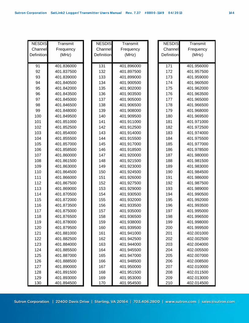
NESDIS Transmit NESDIS Transmit NESDIS TransmitChannel Frequency Channel Frequency Channel Frequency
Definition (MHz) Definition (MHz) Definition (MHz)
91 401.836000 131 401.896000 171 401.95600092 401.837500 132 401.897500 172 401.95750093 401.839000 133 401.899000 173 401.95900094 401.840500 134 401.900500 174 401.96050095 401.842000 135 401.902000 175 401.96200096 401.843500 136 401.903500 176 401.96350097 401.845000 137 401.905000 177 401.96500098 401.846500 138 401.906500 178 401.96650099 401.848000 139 401.908000 179 401.968000
100 401.849500 140 401.909500 180 401.969500101 401.851000 141 401.911000 181 401.971000102 401.852500 142 401.912500 182 401.972500103 401.854000 143 401.914000 183 401.974000104 401.855500 144 401.915500 184 401.975500105 401.857000 145 401.917000 185 401.977000106 401.858500 146 401.918500 186 401.978500107 401.860000 147 401.920000 187 401.980000108 401.861500 148 401.921500 188 401.981500109 401.863000 149 401.923000 189 401.983000110 401.864500 150 401.924500 190 401.984500111 401.866000 151 401.926000 191 401.986000112 401.867500 152 401.927500 192 401.987500113 401.869000 153 401.929000 193 401.989000114 401.870500 154 401.930500 194 401.990500115 401.872000 155 401.932000 195 401.992000116 401.873500 156 401.933500 196 401.993500117 401.875000 157 401.935000 197 401.995000118 401.876500 158 401.936500 198 401.996500119 401.878000 159 401.938000 199 401.998000120 401.879500 160 401.939500 200 401.999500121 401.881000 161 401.941000 201 402.001000122 401.882500 162 401.942500 202 402.002500123 401.884000 163 401.944000 203 402.004000124 401.885500 164 401.945500 204 402.005500125 401.887000 165 401.947000 205 402.007000126 401.888500 166 401.948500 206 402.008500127 401.890000 167 401.950000 207 402.010000128 401.891500 168 401.951500 208 402.011500129 401.893000 169 401.953000 209 402.013000130 401.894500 170 401.954500 210 402.014500
Sutron Corporation SatLink2 Logger/Transmitter Users Manual Rev. 7.37 #8800-1149 04/2013 144

NESDIS Transmit NESDIS TransmitChannel Frequency Channel Frequency
Definition (MHz) Definition (MHz)
211 402.016000 251 402.076000212 402.017500 252 402.077500213 402.019000 253 402.079000214 402.020500 254 402.080500215 402.022000 255 402.082000216 402.023500 256 402.083500217 402.025000 257 402.085000218 402.026500 258 402.086500219 402.028000 259 402.088000220 402.029500 260 402.089500221 402.031000 261 402.091000222 402.032500 262 402.092500223 402.034000 263 402.094000224 402.035500 264 402.095500225 402.037000 265 402.097000226 402.038500 266 402.098500
227 402.040000228 402.041500229 402.043000230 402.044500231 402.046000232 402.047500233 402.049000234 402.050500235 402.052000236 402.053500237 402.055000238 402.056500239 402.058000240 402.059500241 402.061000242 402.062500243 402.064000244 402.065500245 402.067000246 402.068500247 402.070000248 402.071500249 402.073000250 402.074500
** NOTE The international channels are defined as channel 1 – 33. The relationship of international channels to the numbering of 1-266 is the following: Ch 1 international = 202, Ch 2 international = 204 etc until Ch 33 international = 266. For example, ch 20 international = 240. In general, the channel number above = 2*(international channel) +200.
Sutron Corporation SatLink2 Logger/Transmitter Users Manual Rev. 7.37 #8800-1149 04/2013 145

1200 BPS CHANNEL ASSIGNMENTSNOTE: Enter channel number into Satlink by selecting the baud rate and the chanel number without the "A".
NESDIS Transmit NESDIS TransmitChannel Frequency Channel Frequency
Definition (MHz) Definition (MHz)
1 A 401.701750 31 A 401.7917502 A 401.704750 32 A 401.7947503 A 401.707750 33 A 401.7977504 A 401.710750 34 A 401.8007505 A 401.713750 35 A 401.8037506 A 401.716750 36 A 401.8067507 A 401.719750 37 A 401.8097508 A 401.722750 38 A 401.8127509 A 401.725750 39 A 401.815750
10 A 401.728750 40 A 401.81875011 A 401.731750 41 A 401.82175012 A 401.734750 42 A 401.82475013 A 401.737750 43 A 401.82775014 A 401.740750 44 A 401.83075015 A 401.743750 45 A 401.83375016 A 401.746750 46 A 401.83675017 A 401.749750 47 A 401.83975018 A 401.752750 48 A 401.84275019 A 401.755750 49 A 401.84575020 A 401.758750 50 A 401.84875021 A 401.761750 51 A 401.85175022 A 401.764750 52 A 401.85475023 A 401.767750 53 A 401.85775024 A 401.770750 54 A 401.86075025 A 401.773750 55 A 401.86375026 A 401.776750 56 A 401.86675027 A 401.779750 57 A 401.86975028 A 401.782750 58 A 401.87275029 A 401.785750 59 A 401.87575030 A 401.788750 60 A 401.878750
Sutron Corporation SatLink2 Logger/Transmitter Users Manual Rev. 7.37 #8800-1149 04/2013 146

NESDIS Transmit NESDIS TransmitChannel Frequency Channel Frequency
Definition (MHz) Definition (MHz)
61 A 401.881750 97 A 401.98975062 A 401.884750 98 A 401.99275063 A 401.887750 99 A 401.99575064 A 401.890750 100 A 401.99875065 A 401.893750 101 A 402.00175066 A 401.896750 102 A 402.00475067 A 401.899750 103 A 402.00775068 A 401.902750 104 A 402.01075069 A 401.905750 105 A 402.01375070 A 401.908750 106 A 402.01675071 A 401.911750 107 A 402.01975072 A 401.914750 108 A 402.02275073 A 401.917750 109 A 402.02575074 A 401.920750 110 A 402.02875075 A 401.923750 111 A 402.03175076 A 401.926750 112 A 402.03475077 A 401.929750 113 A 402.03775078 A 401.932750 114 A 402.04075079 A 401.935750 115 A 402.04375080 A 401.938750 116 A 402.04675081 A 401.941750 117 A 402.04975082 A 401.944750 118 A 402.05275083 A 401.947750 119 A 402.05575084 A 401.950750 120 A 402.05875085 A 401.953750 121 A 402.06175086 A 401.956750 122 A 402.06475087 A 401.959750 123 A 402.06775088 A 401.962750 124 A 402.07075089 A 401.965750 125 A 402.07375090 A 401.968750 126 A 402.07675091 A 401.971750 127 A 402.07975092 A 401.974750 128 A 402.08275093 A 401.977750 129 A 402.08575094 A 401.980750 130 A 402.08875095 A 401.983750 131 A 402.09175096 A 401.986750 132 A 402.094750
133 A 402.097750
Sutron Corporation SatLink2 Logger/Transmitter Users Manual Rev. 7.37 #8800-1149 04/2013 147
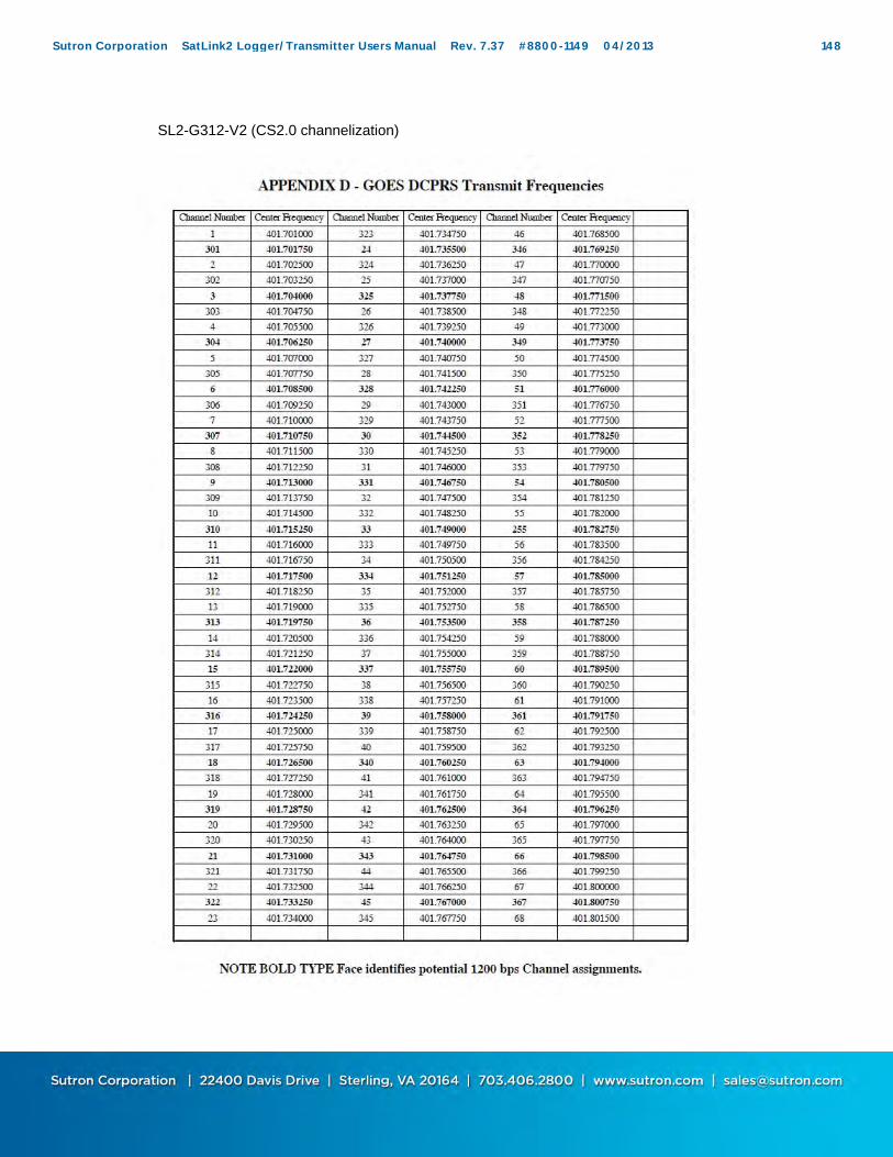
SL2-G312-V2 (CS2.0 channelization)
Sutron Corporation SatLink2 Logger/Transmitter Users Manual Rev. 7.37 #8800-1149 04/2013 148
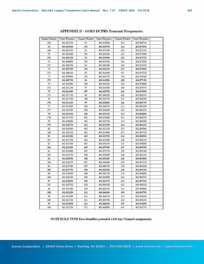
Sutron Corporation SatLink2 Logger/Transmitter Users Manual Rev. 7.37 #8800-1149 04/2013 149

Sutron Corporation SatLink2 Logger/Transmitter Users Manual Rev. 7.37 #8800-1149 04/2013 150

Sutron Corporation SatLink2 Logger/Transmitter Users Manual Rev. 7.37 #8800-1149 04/2013 151

APPENDIX H: METEOSAT
IMPORTANT NOTE: Carefully review the channel assignment from EUMETSAT. The original channel numbering system was regional channels 1 – 33. The METEOSAT SECOND GENERATION (MSG) has channel numbering from 1 – 223. Be absolutely positive as to which channel is assigned and verify the frequency. Satlink only understands the MSG assignments (1-223) and if the assignments are given in terms of the original series, then cross the channel numbers over to the MSG numbers and enter them into Satlink. (The “R” prefix on the channel number is not entered into Satlink)
METEOSAT CHANNEL ASSIGNMENTS
METEOSAT METEOSAT Transmit METEOSAT METEOSAT Transmit METEOSAT METEOSAT Transmit"MSG" original Frequency "MSG" original Frequency "MSG" original Frequency
Channel regional (MHz) Channel regional (MHz) Channel regional (MHz)Definition Definition Definition
R001 R1 402.101500 R031 R16 402.146500 R061 R31 402.191500R002 402.103000 R032 402.148000 R062 402.193000R003 R2 402.104500 R033 R17 402.149500 R063 R32 402.194500R004 402.106000 R034 402.151000 R064 402.196000R005 R3 402.107500 R035 R18 402.152500 R065 R33 402.197500R006 402.109000 R036 402.154000 R066 402.199000R007 R4 402.110500 R037 R19 402.155500 R067 402.200500R008 402.112000 R038 402.157000 R068 402.202000R009 R5 402.113500 R039 R20 402.158500 R069 402.203500R010 402.115000 R040 402.160000 R070 402.205000R011 R6 402.116500 R041 R21 402.161500 R071 402.206500R012 402.118000 R042 402.163000 R072 402.208000R013 R7 402.119500 R043 R22 402.164500 R073 402.209500R014 402.121000 R044 402.166000 R074 402.211000R015 R8 402.122500 R045 R23 402.167500 R075 402.212500R016 402.124000 R046 402.169000 R076 402.214000R017 R9 402.125500 R047 R24 402.170500 R077 402.215500R018 402.127000 R048 402.172000 R078 402.217000R019 R10 402.128500 R049 R25 402.173500 R079 402.218500R020 402.130000 R050 402.175000 R080 402.220000R021 R11 402.131500 R051 R26 402.176500 R081 402.221500R022 402.133000 R052 402.178000 R082 402.223000R023 R12 402.134500 R053 R27 402.179500 R083 402.224500R024 402.136000 R054 402.181000 R084 402.226000R025 R13 402.137500 R055 R28 402.182500 R085 402.227500R026 402.139000 R056 402.184000 R086 402.229000R027 R14 402.140500 R057 R29 402.185500 R087 402.230500R028 402.142000 R058 402.187000 R088 402.232000R029 R15 402.143500 R059 R30 402.188500 R089 402.233500R030 402.145000 R060 402.190000 R090 402.235000
Sutron Corporation SatLink2 Logger/Transmitter Users Manual Rev. 7.37 #8800-1149 04/2013 152
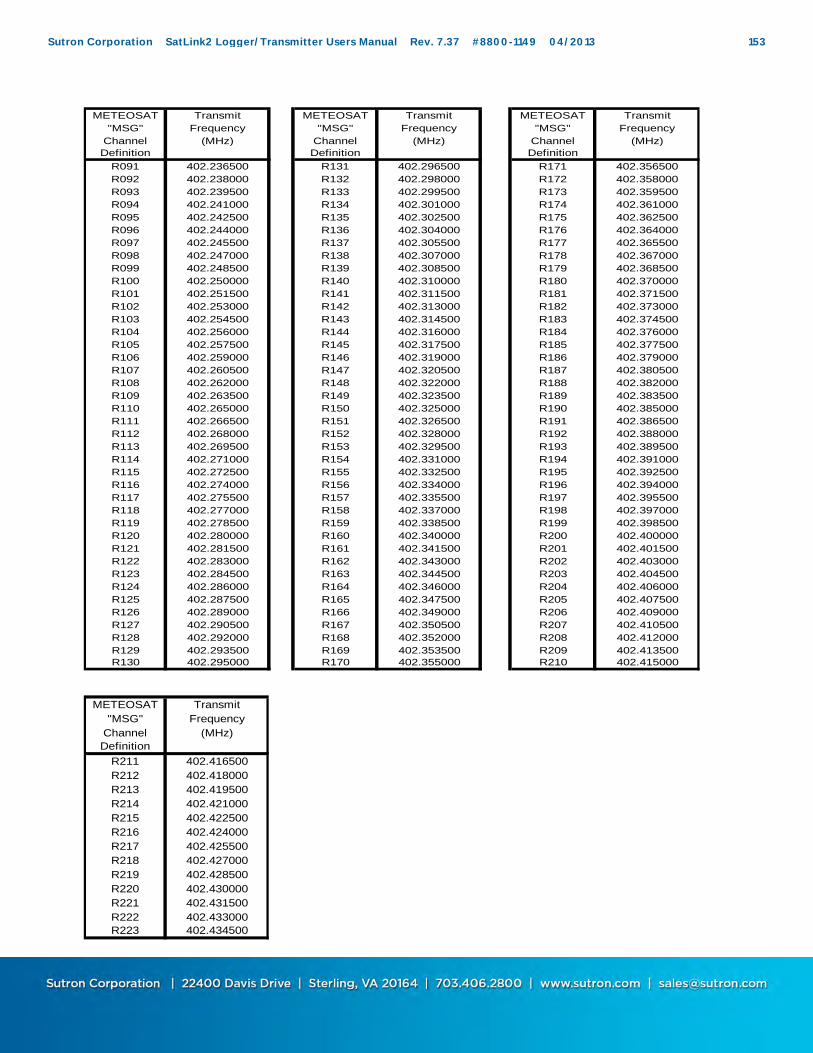
METEOSAT Transmit METEOSAT Transmit METEOSAT Transmit"MSG" Frequency "MSG" Frequency "MSG" Frequency
Channel (MHz) Channel (MHz) Channel (MHz)Definition Definition Definition
R091 402.236500 R131 402.296500 R171 402.356500R092 402.238000 R132 402.298000 R172 402.358000R093 402.239500 R133 402.299500 R173 402.359500R094 402.241000 R134 402.301000 R174 402.361000R095 402.242500 R135 402.302500 R175 402.362500R096 402.244000 R136 402.304000 R176 402.364000R097 402.245500 R137 402.305500 R177 402.365500R098 402.247000 R138 402.307000 R178 402.367000R099 402.248500 R139 402.308500 R179 402.368500R100 402.250000 R140 402.310000 R180 402.370000R101 402.251500 R141 402.311500 R181 402.371500R102 402.253000 R142 402.313000 R182 402.373000R103 402.254500 R143 402.314500 R183 402.374500R104 402.256000 R144 402.316000 R184 402.376000R105 402.257500 R145 402.317500 R185 402.377500R106 402.259000 R146 402.319000 R186 402.379000R107 402.260500 R147 402.320500 R187 402.380500R108 402.262000 R148 402.322000 R188 402.382000R109 402.263500 R149 402.323500 R189 402.383500R110 402.265000 R150 402.325000 R190 402.385000R111 402.266500 R151 402.326500 R191 402.386500R112 402.268000 R152 402.328000 R192 402.388000R113 402.269500 R153 402.329500 R193 402.389500R114 402.271000 R154 402.331000 R194 402.391000R115 402.272500 R155 402.332500 R195 402.392500R116 402.274000 R156 402.334000 R196 402.394000R117 402.275500 R157 402.335500 R197 402.395500R118 402.277000 R158 402.337000 R198 402.397000R119 402.278500 R159 402.338500 R199 402.398500R120 402.280000 R160 402.340000 R200 402.400000R121 402.281500 R161 402.341500 R201 402.401500R122 402.283000 R162 402.343000 R202 402.403000R123 402.284500 R163 402.344500 R203 402.404500R124 402.286000 R164 402.346000 R204 402.406000R125 402.287500 R165 402.347500 R205 402.407500R126 402.289000 R166 402.349000 R206 402.409000R127 402.290500 R167 402.350500 R207 402.410500R128 402.292000 R168 402.352000 R208 402.412000R129 402.293500 R169 402.353500 R209 402.413500R130 402.295000 R170 402.355000 R210 402.415000
METEOSAT Transmit"MSG" Frequency
Channel (MHz)Definition
R211 402.416500R212 402.418000R213 402.419500R214 402.421000R215 402.422500R216 402.424000R217 402.425500R218 402.427000R219 402.428500R220 402.430000R221 402.431500R222 402.433000R223 402.434500
Sutron Corporation SatLink2 Logger/Transmitter Users Manual Rev. 7.37 #8800-1149 04/2013 153

APPENDIX I: INSAT
INSAT is not supported by all versions of Satlink Logger software. Only versions 6.03 and newer support INSAT. INSAT units have an auxiliary cable that provides Clock, Data and Transmit RF Gate that is provided on a special connector. (TBD) Transmission time and INSAT: An INSAT transmission is really a set of either three or six individual transmissions made within a ten minute time window. The ten minutes get spilt up into either three or six separate windows, during each of which one transmission will occur. The exact time of each transmission is randomized during that short window. Whether three or six transmission are made depends on the amount of data to be transmitted. If up to ten sensor readings are to be transmitted, three transmission are made; more than 10 sensor readings will result in six transmissions. If data is given to Satlink by another device, then the amount of data given will determine how many transmissions are made. If six transmissions are being made, the first three are made with the user-set satellite ID. The second three are made with either the second satellite ID (if the user entered it), or by transforming the first satellite ID (more details on the second satellite ID follow). The Offset and Interval settings of Satlink’s scheduled transmission determine when the ten minute window starts. For example, if you set the Offset to 00:20:00 and the Interval to 01:00:00, Satlink will make the transmissions once an hour, sometime between 20 and 30 minutes past the hour. You cannot setup Satlink to do random transmission for INSAT. Second satellite ID (versions 5.06 and newer only) If INSAT is selected as the transmission type in the scheduled tab of the Communicator program, a field for the second satellite ID appears. The use of this field is optional. By setting the field value to 0 or to 0xFFFFFFFF, the user indicates that he does not want to use this field. The second satellite ID would be used for the second batch of three transmissions. If the second ID is not set, and six transmission are being made, a transformation of the original satellite ID will be used.
Transmission data and INSAT:
Sutron Corporation SatLink2 Logger/Transmitter Users Manual Rev. 7.37 #8800-1149 04/2013 154
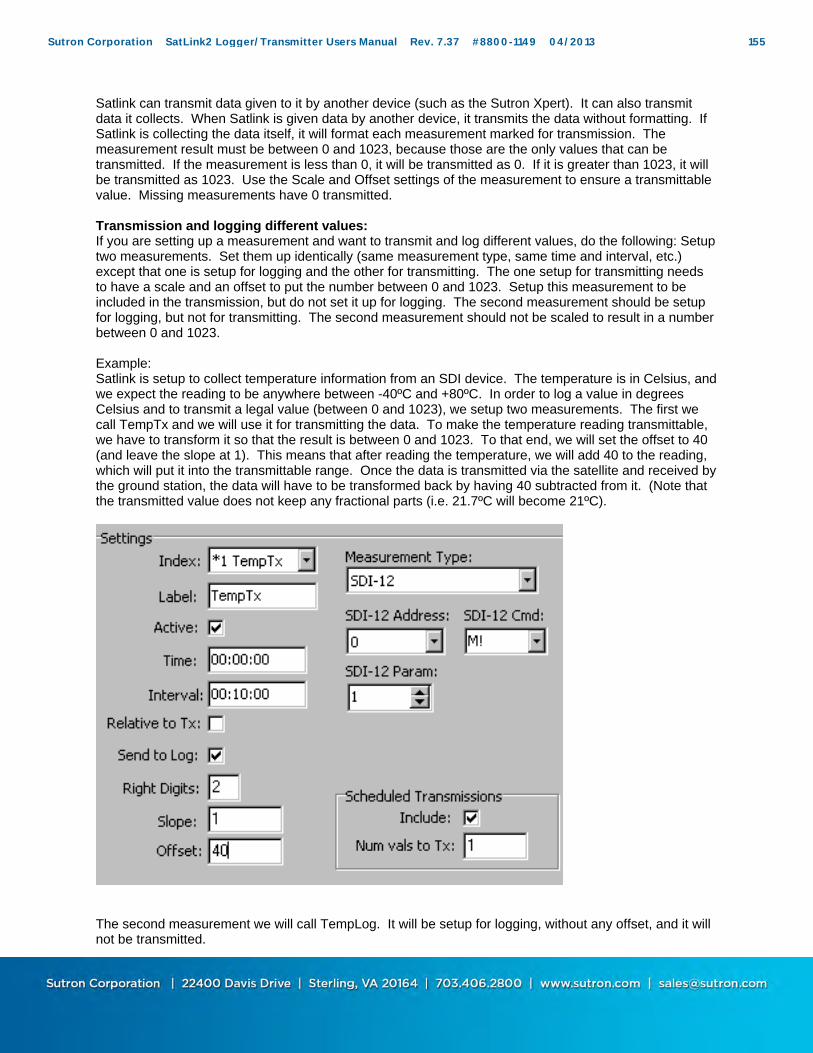
Satlink can transmit data given to it by another device (such as the Sutron Xpert). It can also transmit data it collects. When Satlink is given data by another device, it transmits the data without formatting. If Satlink is collecting the data itself, it will format each measurement marked for transmission. The measurement result must be between 0 and 1023, because those are the only values that can be transmitted. If the measurement is less than 0, it will be transmitted as 0. If it is greater than 1023, it will be transmitted as 1023. Use the Scale and Offset settings of the measurement to ensure a transmittable value. Missing measurements have 0 transmitted. Transmission and logging different values: If you are setting up a measurement and want to transmit and log different values, do the following: Setup two measurements. Set them up identically (same measurement type, same time and interval, etc.) except that one is setup for logging and the other for transmitting. The one setup for transmitting needs to have a scale and an offset to put the number between 0 and 1023. Setup this measurement to be included in the transmission, but do not set it up for logging. The second measurement should be setup for logging, but not for transmitting. The second measurement should not be scaled to result in a number between 0 and 1023. Example: Satlink is setup to collect temperature information from an SDI device. The temperature is in Celsius, and we expect the reading to be anywhere between -40ºC and +80ºC. In order to log a value in degrees Celsius and to transmit a legal value (between 0 and 1023), we setup two measurements. The first we call TempTx and we will use it for transmitting the data. To make the temperature reading transmittable, we have to transform it so that the result is between 0 and 1023. To that end, we will set the offset to 40 (and leave the slope at 1). This means that after reading the temperature, we will add 40 to the reading, which will put it into the transmittable range. Once the data is transmitted via the satellite and received by the ground station, the data will have to be transformed back by having 40 subtracted from it. (Note that the transmitted value does not keep any fractional parts (i.e. 21.7ºC will become 21ºC).
The second measurement we will call TempLog. It will be setup for logging, without any offset, and it will not be transmitted.
Sutron Corporation SatLink2 Logger/Transmitter Users Manual Rev. 7.37 #8800-1149 04/2013 155

Note that even though two measurements are setup, since their measurement type and schedules are identical, Satlink will only take one reading from the SDI sensor. This ensures consistency between the logged and transmitted values. Formatting measurement data into columns: A transmitted message will contain ten columns, each with a measurement reading. Measurements get transmitted in the order they have been setup. If measurement one has been setup to transmit four values, and measurement two setup to transmit two values, then the transmitted data will contain measurement one in the first four columns, and measurement two in the next two. The only way to get a measurement in a specific column is to setup the measurements sequentially. For example, if you wish to transmit a rain reading in column four and have the first three columns blank, you will need to setup measurement one to be a dummy measurement that will transmit three readings, and setup rain to be measurement two that will transmit one reading. Mixing measurement and external data: Satlink can do a merged data transmission in which it formats the first three transmissions from sensor readings it has made, and transmits data given to it by another device in the last three transmissions. In order for merged data mode to work, Satlink must be setup to transmit ten or less sensor readings, otherwise it will fill up all six transmissions with its own data.
Sutron Corporation SatLink2 Logger/Transmitter Users Manual Rev. 7.37 #8800-1149 04/2013 156

APPENDIX J: 40 WATT SATLINK VARIANT (SL2-B40W-1)
A variant of Satlink2 is produced which is essentially a modified Satlink2 that outputs 40 Watts of RF output power. This version is designed for stations that require an Omnidirectional antenna either because the station is moving or multiple satellites are required. A buoy station is a good example of this application. This 40 Watt mode is not supported by all versions of Satlink Logger software. Only versions 6.08 and newer support 40 Watts in addition to the hardware modifications. GENERAL: The 40 Watt Transmitter has been accomplished by adding a 6 dB gain amplifier to the top of a Satlink 2. This amplifier adds 6 dB to the top of a 10 watt setting (+40 dBm) and results in a 40 Watt output (46 dBm) at 12.5 Volts. ENHANCED CAPABILITIES:
40 Watts output for Omnidirectional antenna Power output is the same for any baud rate 100, 300 or 1200 bps. The switched 12 Vdc output (for sensor warmup) now turns on (in addition to the prior
capabilities) just prior to a transmission and turns off following the transmission. This is configured to control and external switch to power the booster amplifier.
Sutron Corporation SatLink2 Logger/Transmitter Users Manual Rev. 7.37 #8800-1149 04/2013 157
INSTALLATION: The installation of a SL2-B40W-1 is approximately the same as installing a regular Satlink 2. Care should be taken to accomplish the following:
Never mount Satlink2 in a wet and condensing environment. This may cause significant damage to the connectors.
Always be sure to provide a high quality return to ground for proper lightning protection.
Always use heavy gauge wire, such as 14 or 16 Ga for connections to batteries if the supplied cables are not long enough. It is highly recommended to NEVER extend the DC cables to the battery if at all possible.
If using the optional switch to control the power to the amplifier, verify that all connections are per the included instructions. Securely mount all switches and tie all cables to prevent accidental disconnections.
NEVER USE A YAGI antenna with the 40 watt transmitter. Only use the 3 or 3.5 dB gain OMNI antenna or power levels will be exceeded on the satellite.
OPERATION: The customer will not experience any difference in operation of the Satlink2 as compared to a standard Satlink 2. When ordered, the Satlink 2 40 Watt (SL2-B40W-1) will be shipped factory set at the proper 40 Watt level. No further adjustments are available to the customer. However, the customer must pay particularly close attention to the DC power connections to the battery. The amplifier will draw significantly more current than a standard Satlink 2 in order to generate 40 Watts. All connections should be made directly to the battery and if some additional wiring is required, then heavy gauge wiring is required. (See above) Unlike regular Satlink 2 operation where 7 watts is used for 100 and 300 bps and 14 watts is used for 1200 bps, the SL2-B40W-1 will transmit the same 40 Watt level for all baud rates, 100, 300 and 1200 bps. QUIESCENT POWER : The Satlink will consume the same amount of standby current as long as the amplifier is switched using the optional amplifier switch kit. If this switch option is not used, then it will be up to a secondary payload/logger to switch the power. If non switched operation is desired, then the quiescent power will increase by approximately 400 ma.
Sutron Corporation SatLink2 Logger/Transmitter Users Manual Rev. 7.37 #8800-1149 04/2013 158

APPENDIX K: MOUNTING PATTERN
1 AGND3INPUT2 4
2.5 Vref
ANALOG(0-5 Volts)
SW +12
SW GND
CASEGND
Sutron Corporation SatLink2 Logger/Transmitter Users Manual Rev. 7.37 #8800-1149 04/2013 159
APPENDIX L: ARGOS
ARGOS is not supported by all versions of Satlink Logger software. Only versions 6.08 and newer support ARGOS. ARGOS data gets formatted in a unique way. Each measurement marked for transmission (see the section on measurements on page 47) will be encoded into a specific number of bits. The number of bits defaults to 16. The “Label” field of the measurement can be used to specify how many bits to encode for that measurement. For example, if the “Label” field is set to be “Stg:32”, then all readings of that measurement to be transmitted will be encoded into 32 bits. How many readings are to be transmitted is specified using the “Num vals to Tx” field. ARGOS allows up to 256 bits of sensor data (unless the ID is a 28 bit ID in which case only 248 bits are allowed). With the default setting of 16 bits per reading, 16 different readings could be transmitted. Those could be 16 readings of the same measurement, or 8 readings of two different measurements, or any other combination.
Sutron Corporation SatLink2 Logger/Transmitter Users Manual Rev. 7.37 #8800-1149 04/2013 160
Index
0 0 to 5 Volts ....................................................................... 54
4 4.11 ............................................................................. 30, 36
6 6461-1230-1 ................................................................... 120 6461-1241 ......................................................................... 18
8 8210
External Installation ................................................... 102 Internal Installation..................................................... 102 operation with 8210 .................................................... 119
8400 Measurement type ........................................................ 53 Sensor Name ................................................................ 53 Sutron DDR .................................................................. 53
8400 comm failure Error ................................................. 109 8800-1127 ...................................................................... 124
A Active
Measurement Active ..................................................... 48 Active measurement has zero interval Error ................... 108 Advanced Scheduling ................................................. 76, 79 Alarm
high............................................................................... 59 into ............................................................................... 59 low ................................................................................ 59 Measurement ................................................................ 58 out of ............................................................................ 59 ROC ............................................................................. 60 Settings ......................................................................... 58 Settings ......................................................................... 82
Alarm Interval ................................................................... 82 Random Transmissions ................................................ 59
Alarms Set Up .................................................................. 58 Already Transmitting Error ............................................. 108 Analog
connector ............................................................... 19, 20 Analog measurement ........................................................ 54
0 to 5 Volts ................................................................... 54 differential .................................................................... 55 ratiometric .................................................................... 54
Analog measurements bridge ........................................................................... 55 Channels ....................................................................... 54
negative voltage measurements ................................... 55 switched 12V ............................................................... 55 Warmup time ............................................................... 55
Antenna Part Number ............................................................... 105 YAGI ........................................................................... 12
Append Data .................................................................... 77 Append Lat/Long ............................... 75, 82, 128, 130, 131 Append Options ............................................................... 75 Append Quality .......................................... 54, 75, 130, 131 ARGOS .......................................................................... 162 ASCII Column Formatting ....................................... 75, 134 ASCII Sensor Formatting ......................................... 75, 135 autostart ............................................................................ 26 Autostart failed-invalid setup Error ................................ 109 averaging .......................................................................... 49 Averaging Time ............................................................... 49
B Bad amp temp Error ....................................................... 108 Bad forward power Error ............................................... 108 Batt Voltage ..................................................................... 75 Battery .............................................................................. 15
Low Voltage Error ..................................................... 108 Voltage
Measurement Type .................................................. 54 Voltage Under Load ..............................54, 128, 130, 131 Zero Voltage Reported ................................................. 75
binary formatting ............................................................ 133 Bluetooth .......................................................................... 43 bootloader ................................................................. 25, 111 bridge ............................................................................... 55 Buffer ......................................................................... 76, 77
append data .................................................................. 77 circular ......................................................................... 80 clear data ...................................................................... 77 control .......................................................................... 76 data buffer empty ......................................................... 76 load from file ............................................................... 77 save to file .................................................................... 77 view data ...................................................................... 77
Burst Interval .................................................................... 82 Bypass GPS ...................................................................... 76
C cable
RG-8 .......................................................................... 100 SMA/RG-58 ............................................................... 100
Cannot tune modulator Error .......................................... 108 Capture Debug Info .......................................................... 93 Channel
Transmission Channel .................................................. 75 Channelization
Sutron Corporation SatLink2 Logger/Transmitter Users Manual Rev. 7.37 #8800-1149 04/2013 161

GOES 100 and 300 ..................................................... 143 GOES 1200 ................................................................ 146 Meteosat ..................................................................... 152
chip test ........................................................................... 111 CIMEL .............................................................................. 80 Cimel comm failure Error ............................................... 109 circular buffer ............................................................. 27, 80 Clear Data ................................................................... 64, 77 Clear Log .......................................................................... 65 clear status ....................................................................... 45 Command line ................................................................. 115 Configuring Satlink logger ............................................... 26 Connected
work connected ............................................................ 37 connections ............................................................... 11, 126 Continuing Random Tx Status ........................................ 110 current version
Communicator .............................................................. 37 Customer support
phone .......................................................................... 121 Cutoff Voltages ................................................................. 92
D Data
buffers .......................................................................... 27 external ....................................................... 127, 129, 131 formating .................................................. See formatting merging ........................................................................ 76
Data Buffer Empty ............................................................ 76 Data Merge ....................................................................... 76 Data tab
Satlink Logger Communicator ..................................... 63 Deadband
Alarm ........................................................................... 59 Debug
Capturing Debug Info ................................................... 92 Debug Info in Separate Window ....................................... 37 Defaults
Setting Satlink to Defaults ............................................ 92 Diagnostic ......................................................................... 92
log test .......................................................................... 92 differential ........................................................................ 55 Display .............................................................................. 37 Dumb Logger .................................................................... 80
E Enable Auto Update .......................................................... 45 enclosure ......................................................................... 100
Nema .......................................................................... 100 Encoding data ................................................................... 26 Encoding data for Tx Status ............................................ 110 Equation processing .......................................................... 56 Error Messages ............................................................... 108 Error syncing clock to GPS Error ................................... 108 Export Log ........................................................................ 64 external data .................................. 27, 75, 77, 127, 129, 131
F Factory Defaults.......................................................... 92, 93
Failed to log-log busy Error ........................................... 109 Failsafe
reset .............................................................................. 45 Reset Button................................................................. 19 tripped ........................................................................ 107
Failsafe not reset Error ................................................... 108 Failsafe tripped Error ..................................................... 108 Fault LED ......................................................................... 19 Finalize ............................................................................. 36 Find Satlink .................................................... 31, 34, 35, 37 Firmware
Upgrading .................................................................... 95 Version......................................................................... 46
floating point .................................................................... 56 Forced Measurement .................................................. 60, 64 Forced measurement in progress Error ........................... 108 Forced transmission ................................................. 82, 105 Formatting ........................................................................ 77
ASCII Column ..................................................... 75, 134 ASCII Sensor ....................................................... 75, 135 pseudobinary .............................................................. 127 scheduled pseudobinary ............................................. 129 SHEF ......................................................................... 131 six-bit binary .............................................................. 133
frequency discipline ......................................................... 87 Frequency discipline ........................................................ 26 Frequency discipline failed Error ................................... 108 Frequency discipline started/completed Status ............... 110 fuse ........................................................................... 14, 101
G Get Setup from Satlink ..................................................... 35 Get Status ......................................................................... 45 GPS ............................................................................ 85–87
antenna ........................................................... 18, 87, 101 satellite acquisition ...................................................... 26 sync .............................................................................. 87
GPS failed to acquire time Error .................................... 108 GPS satellite acquisition started Status .......................... 110 GPS satellite acquisition Status ...................................... 110 GPS time sync started/succeeded Status ........................ 110 GPS use disabled Status ................................................. 110 Graph
Printing ........................................................................ 68 Scrolling ....................................................................... 68 Zooming ....................................................................... 68
H Heap crash Error ............................................................ 109 HyperTerminal ....................................................... 111, 115
I Idling Status ................................................................... 110 IEEE32 ............................................................................. 56 Include
Measurement ................................................................ 58 Initialization failed Error ................................................ 108 INSAT ............................................................................ 154
Sutron Corporation SatLink2 Logger/Transmitter Users Manual Rev. 7.37 #8800-1149 04/2013 162
installation ...................................................................... 100 Installation
8210 ............................................................................ 102 Stand Alone ................................................................ 100 Xpert ........................................................................... 103
interleaver ......................................................................... 80 Internal error Error .................................................. 109, 110 Internal timing error Error .............................................. 108 Interval .............................................................................. 82
Alarm ........................................................................... 59 Measurement Interval ................................................... 49 Normal ......................................................................... 59 Sampling limits ............................................................ 49 Transmission Interval ................................................... 75
Invalid channel Error ...................................................... 108 Invalid satellite type Error .............................................. 108 iPaq ................................................................................... 30
L label
measurement label ........................................................ 48 Label
SHEF formatting ........................................................ 131 Last Data ........................................................................... 60 Last frequency discipline result ........................................ 87 latitude ................................................................... 128, 130 LED ................................................................................. 11 Local Time Offset ............................................................. 44 Locking loops Status ....................................................... 110 Log .................................................................................... 64
Capacity........................................................................ 11 Clearing ........................................................................ 65 Download Command Line ......................................... 115 Downloading ................................................................ 65 Format .......................................................................... 66 Test ............................................................................... 92
Log Download Quick ............................................................................ 33
Log Format Satlink Standard ........................................................... 66 Sequential B ................................................................. 66 Sutron Standard CSV ................................................... 66
Log GPS Updates ............................................................. 92 longitude ................................................................ 128, 130 Loops not locked Error ................................................... 108
M M in transmission ............................................................. 64 Main .................................................................................. 34
Communicator Main tab ............................................... 44 main application................................................................ 25 Malfunction ...................................................................... 28 Manual Entry .................................................................... 53
Measurement Type ....................................................... 53 Measurement ................................................................... 47
Active ........................................................................... 48 Alarm ........................................................................... 58 force ............................................................................. 60 force all......................................................................... 64 general settings ............................................................. 48
Include ......................................................................... 58 interval ....................................................................... 131 Interval ......................................................................... 49 label ............................................................................. 48 Label setting............................................................... 131 Log ............................................................................... 64 Minimum interval ........................................................ 49 missing ................................................................. 64, 107 Num Vals to Tx ........................................................... 58 Offset ........................................................................... 56 quality .......................................................................... 60 Relative to Tx .............................................................. 49 Right Digits .................................................................. 49 SDI-12 ......................................................................... 52 SDI-12 Address ........................................................... 52 SDI-12 Param .............................................................. 52 Send to Log .................................................................. 49 Slope ............................................................................ 56 understanding ............................................................... 27 update .......................................................................... 60
Measurement Error ......................................................... 108 Measurement Index .......................................................... 59 Measurement Type ........................................................... 52
8400 ............................................................................. 53 Battery Voltage ............................................................ 54 Manual Entry ............................................................... 53 Satlink Temperature ..................................................... 55 SDI-12 ......................................................................... 52 Tipping Bucket ...................................................... 52, 55
memory test .................................................................... 111 message length ................................................................. 77 Meteosat ......................................................................... 152 MinMax ............................................................................ 50
Transmission encoding ................................................ 51 transmission setup ........................................................ 52
Missed scheduled measurement Error ............................ 108 missing data ...................................................... 64, 107, 131 Modem ................................................................. 31, 37, 42
auto-answer .................................................................. 42 Upgrading Satlink remotely ......................................... 42
Modulator not configured Error ..................................... 108 Mounting Pattern ............................................................ 160 multiple measurement
SDI-12 ......................................................................... 53 Mute Power Amp ............................................................. 84
N negative voltage measurements ........................................ 55 Nema .............................................................................. 100 NESDIS ............................................................................ 76 No Alarms Set Up ............................................................ 58 NOCOM ................................................................. 119, 123 Normal Interval ................................................................ 82
Random Transmissions ................................................ 59 Num vals to Tx ................................................................. 58 Number of Tx per Burst ................................................... 82
O Offset
Measurement Offset ..................................................... 56
Sutron Corporation SatLink2 Logger/Transmitter Users Manual Rev. 7.37 #8800-1149 04/2013 163
Opcodes Command reference ................................................... 124
operating voltage ............................................................. 11 Out of heap memory Error .............................................. 109
P Part numbers ................................................................... 105 Password ........................................................................... 37 Pic comm failure Error ................................................... 108 Pocket PC ................................................................... 30, 40 Power ................................................................................ 12 Power supply .................................................................... 15 Preparing data ................................................................... 27 pseudobinary format ......................................................... 75
random transmission ................................................... 127 scheduled transmission ............................................... 129
PULSE12 .......................................................................... 57
Q quality ..................................................................... 130, 131 Quick View Status ............................................................ 32 Quiescent Current Consumption ....................................... 12
R Random transmissions ...................................................... 81 Random Tx preparation started Status ............................ 110 Random Tx successfully completed Status ..................... 110 ratiometric ......................................................................... 54 Relative to Tx
Measurement Relative to Tx................................. 49, 107 reset failsafe ...................................................................... 45 Right Digits..................................................................... 133
Measurement Setting .................................................... 49 RS-232 .............................................................................. 17 running ........................................................................ 25, 36
S sampling ........................................................................... 49 Sampling interval .............................................................. 49 Sampling speed ................................................................. 54 SatComm ......................................................................... 40 Satellite ID not set Error ................................................. 108 Satellite Type
Transmission Satellite Type ......................................... 75 Satlink Display ................................................................. 37 Satlink Logger Communicator .......................................... 30 Satlink Temperature
Measurement Type ....................................................... 55 Say Hello .......................................................................... 34 Scheduled transmissions ............................................. 26, 69 Scheduled Tx preparation started Status ......................... 110 Scheduled Tx successfully completed Status .................. 110 Scheduled Tx Tab
Satlink Logger Communicator ..................................... 69 SDI-12
Address ................................................................. 52, 126 command .............................................................. 52, 126
connector ..................................................................... 18 Measurement Type ...................................................... 52 minimizing errors ....................................................... 126 multiple measurement .................................................. 53 Overview ................................................................... 125 Param ........................................................................... 52 Pass-thru mode ............................................................. 62 Send SDI-12 Command ............................................... 62 single measurement ...................................................... 53 wiring ......................................................................... 126 www.sdi-12.org ......................................................... 125
SDI-12 comm failure Error ............................................ 108 SDI-12 command empty Error ....................................... 109 Self Test ................................................................... 92, 111 Send SDI-12 Command ................................................... 62 Send Setup to Satlink ....................................................... 35 Send to Log ...................................................................... 64
Measurement Send to Log ........................................... 49 send to sutron ................................................................... 90 Send to Sutron Tx prep started Status ............................ 110 Send to Sutron Tx successfully completed Status .......... 110 sensor data .......................................................... 27, 75, 125
formatting .................................................................... 77 formatting .................................................................... 75
Set Tipping Bucket Count ................................................ 61 Setting time
8210 ................................................................... 119, 120 Satlink .......................................................................... 86
Setup Sending to Satlink ........................................................ 30 Understanding .............................................................. 30
SHEF ........................................................................ 75, 131 SHEFFIX ......................................................................... 75 Show Measurements ........................................................ 64 Show Message .................................................................. 77 signal quality .................................................................... 86 single measurement
SDI-12 ......................................................................... 53 six-bit binary formatting ................................................. 133 Size
Satlink Dimensions ...................................................... 11 Slope
Measurement Slope ...................................................... 56 Software failsafe tripped Error ....................................... 109 software requirements .................................................... 121 Stand Alone Installation ................................................. 100 Start .................................................................................. 36 Station Name .................................................................... 75 Status ................................................................................ 45 Status LED ....................................................................... 18 Stop .................................................................................. 36 stopped ....................................................................... 19, 25 Sutron Standard CSV ....................................................... 66 Sutron’s website
link to ........................................................................... 37 switched 12 Volts ............................................................. 55 System Malfunction ................................................... 28, 32 System time changed Status ........................................... 110
T Temp during last tx .......................................................... 75
Sutron Corporation SatLink2 Logger/Transmitter Users Manual Rev. 7.37 #8800-1149 04/2013 164

Test chip ............................................................................. 111 memory ...................................................................... 111 Self Test ..................................................................... 111
test transmission................................................................ 83 Test Tx preparation started Status ................................... 110 Time
8210 ............................................................................ 120 Format .................................................................... 75, 86 GPS Acquiring ............................................................. 87 Local Time Offset ........................................................ 44 Measurement Time ....................................................... 49 Setting 8210’s Clock .................................................. 119 Setting Satlink’s Clock ................................................. 86 Tx Time ........................................................................ 75 UTC .............................................................................. 86
Time way off Error ......................................................... 109 Tipping bucket
connector ..................................................................... 18 Tipping Bucket ......................................... 47, 52, 55, 56, 61 transmission
length ............................................................................ 77 Transmission ..................................................................... 75
alarms ........................................................................... 82 append lat/long ................................................... 128, 130 buffer control ................................................................ 76 burst .............................................................................. 82 bypass GPS ................................................................... 76 circular buffer ............................................................... 80 data buffer empty ......................................................... 76 forced ................................................................... 76, 105 Forced ........................................................................... 82 formating .................................................. See formatting General Settings ........................................................... 75 Include Measurement ................................................... 58 interleaver ..................................................................... 80 interval ......................................................................... 82 preamble ....................................................................... 80 Random ........................................................................ 81 send to Sutron ............................................................... 90 sensor data ................................................................... 75 test ................................................................................ 83 transmit now ................................................................. 76 Transmit Now ............................................................... 82 Understanding .............................................................. 26 window centering ......................................................... 75
Transmission Status ........................................................ 110 Transmission stopped Status ........................................... 110 Transmit Now ............................................................. 76, 82
Transmitting Status ........................................................ 110 troubleshooting ....................................................... 105–117
diagnostic .................................................. See diagnostic Troubleshooting
Error Messages .......................................................... 108 Tx LED ............................................................................ 19 Tx time
Transmission Time ...................................................... 75
U upg ................................................................................... 37 Upgrading................................................................. 95, 111
Changing Satlink Firmware ......................................... 37 Remotely ...................................................................... 42 using Hyperterminal .................................................. 111 using the bootloader ................................................... 111
User aborted Tx Error .................................................... 109 UTC Time ........................................................................ 44
V version .............................................................................. 30 Version
Bootloader ................................................................... 46 GPS .............................................................................. 46 PIC ............................................................................... 46 Satlink firmware .......................................................... 46
Version history ............................................................... 137 View Data ........................................................................ 77 visual interface ................................................................. 30
W Waiting for post-Tx quiet time to pass Status ................ 110 Waiting for TCXO warmup Status ................................. 110 Waiting for Tx time Status ............................................. 110 Warmup time .................................................................... 55 Weight
Satlink .......................................................................... 11 window centering ....................................................... 27, 75 Work Connected ............................................................... 37
X Xpert .............................................................................. 124
Installation ................................................................. 103
Sutron Corporation SatLink2 Logger/Transmitter Users Manual Rev. 7.37 #8800-1149 04/2013 165