models j43, j63, j83 j44, j64, j84 - 中国百科网-我的实用 …€¦ · · 2016-10-07the...
TRANSCRIPT

RENEWAL PARTS
MODEL J � STYLE K & MHERMETIC COMPRESSORS
Supersedes: 180.23-RP5 (698) Form 180.23-RP5 (1298)
MODELSJ43, J63, J83J44, J64, J84
(See Page 2 for Complete Model Nomenclature)
28946A

YORK INTERNATIONAL2
UNIT NOMENCLATURE
COMPRESSOR IDENTIFICATION
Each compressor is identified by nomenclature asshown below. The nomenclature is printed on a dataplate which is located near the oil pump as shown inFig. 1. When contacting the factory or ordering re-newal parts, include the complete Nomenclature,Serial Number, and Date Code. Be sure that thesenumbers are copied accurately.
FIG. 1 � COMPRESSOR DATA PLATE
LD02975
LD03063
J K 4 3 1 � M H 46/50 S
Compressor Series Motor VendorS = A. O. Smith
Style Style K with Terminal Box and Motor Protector Style M without Factory Mounted Motor Protector
Number of Cylinders Motor Voltage Code4, 6, or 8 17 = 200-3-60
28/59 = 230-3-60/190-3-50Displacement Code 40 = 380-3-60
3 = Short Stroke 46/50 = 460-3-60/380/415-3-504 = Long Stroke 58/70 = 575-3-60/500-3-50
63 = 220-3-5043 = 440-3-50
Number of Unloaders 64 = 346-3-503 = (8 Cyl. Compr.) - % Loading: 100,75,50,25 36 = 363-3-502 = (8 Cyl. Compr.) - % Loading: 100,75,502 = (6 Cyl. Compr.) - % Loading: 100,66,33 Motor Efficiency Rating1 = (8 Cyl. Compr.) - % Loading: 100,50 H = High Efficiency1 = (6 Cyl. Compr.) - % Loading: 100,66 Blank = Standard Efficiency1 = (4 Cyl. Compr.) - % Loading: 100,50
Motor Size CodeM, N, P, Q, S, T or V
NO. OF CYLINDERS4 6 8
3 3.2" 3.0" 3.1"4 3.8" 3.6" 3.7"

FORM 180.23-RP5
3YORK INTERNATIONAL
Model JK and Model JM compressors share the samecompressor bodies and components with the followingdifference: Model JK is supplied with a factory mountedmotor protector, and the JM is supplied LESS the fac-tory mounted motor protector. Model differentiation wasrequired to meet UL requirements.
York Model J Styles K And M Semi Hermetic Compres-sors are industrial duty reciprocating type compressorsdesigned to meet refrigerating and air conditioning re-quirements using either R-22 or R-134a. They are avail-able in 4, 6, and 8 cylinder models in either �short stroke�or �long stroke� versions, as designated by the thirdcharacter in the compressor model number and de-scribed below.
Model J compressor unloading capabilities allow thecompressor flow capacity to modulate as refrigerationload changes occur, improving part load operating effi-ciency and decreasing operating costs. Nominal com-pressor speeds at 60 Hz duty are 1750 RPM; or 1450RPM at 50 Hz duty.
Evolution of the J series compressor has resulted in afield serviceable unit that with proper maintenance willprovide years of reliable cooling service.
J Styles K and M compressors boast an improved oilmanagement system for control of oil flow within thecompressor, along with an added oil temperature safetysystem. This improved oil management system signifi-cantly decreases oil carry over which improves systemheat transfer, operating efficiency, and reliability.
The new oil management system consists of new mo-tor end bearing head that incorporates an oil controlbearing outboard of the two main bearings, and newoil return ports that direct oil back into the crankcase.Oil passes through an eductor prior to entering thecrankcase. Oil that may accumulate in the motor hous-ing will be transported to the crankcase via the eductorpick-up tube.
Crankcase ventilation incorporates an oil mist precipi-tator built into the new pump end bearing head. Vent-
ing from this bearing head to the suction plenum isthrough an external pipe connection.
Cylinder O-rings are now used on all permanentlyloaded cylinders as well as the cylinders that can un-load. These features are shown in Fig. 6, page 10 ofthe maintenance manual, Form 180.23-M5.
Connecting rods now have a drilled port added to pro-vide forced lubrication to the wrist pin. This is essentialfor POE lubricants only. Either rod can be used withmineral oil lubricants.
Oil temp controls include a �high oil temp� cutout set at160°F and an �oil temp inhibit� feature that requires oiltemperature to be at least 15°F above ambient at startup. If this condition is not satisfied, the starting circuitwill not engage. This start inhibit safety ensures thatmigration during the off cycle will not build excessiverefrigerant in the oil. This prevents oil foaming and oilpressure loss.
Normal start up procedures include prelubricating theoil system with a hand pump and allowing the crank-case heater to be energized 24 hours prior to start up.
Normal oil pressure range is 30 � 60 PSID.
PRELUBRICATIONTo ensure long compressor life, prelubrication at startand after long idle periods of several months is recom-mended. This manual prelube is especially importanton R-134a and R-407C units that employ POE type oildue to the polar nature of these oils. This is accom-plished by attaching a hand pump to the valve core-typeaccess port (schrader fitting) on the oil pump.
See pages 17 and 18 for oil priming pump and mainte-nance chart.
Parts and professional service are available throughyour local York Service Office. Contact the office listedon the back cover nearest you. Sales and Service of-fices are also listed on the web athttp://www.york.com/
GENERAL DESCRIPTION

YORK INTERNATIONAL4
LD02966
FIG. 2 � COMPRESSOR
NOTE A:1. Brass pipe adapter by valve manufacturer Mueller.
NOM.VALVE ADAPTER GASKETSIZE2-1/8 A6267 A62612-5/8 A6268 A62613-1/8 A6269 A6262

FORM 180.23-RP5
5YORK INTERNATIONAL
FIG. 3 � COMPRESSOR END VIEWS
LD02967
LD02968
FIG. 4 � UNLOADING DEVICE
ITEM NO. DESCRIPTION PART NUMBERS38 UNLOADER, BLOCKED SUCTION 364-48190-000
38A PISTON 064-48189-000
38B WASHER, SEAL 028-12560-000
38C SCREW, CAP HEX SOCKET 021-17396-000
38D HEAD 013-01671-000
38E SEALER, LOCTITE GRADE AVV 021-17220-000
WASHER, PLAIN SPECIAL38F
RING, COMPRESSION1029-20999-000
NOTES:1. s = Recommended Stock Spare Part2. 1 = Includes Compression Ring and O-Ring

YORK INTERNATIONAL6
FIG. 5 � MANIFOLD ARRANGEMENTS
COMPRESSORITEM NO. DESCRIPTION
4 CYLINDER 6 CYLINDER 8 CYLINDER
1 HOUSING, COMPRESSOR 064-49269-000 064-49270-000 064-49271-0002 HEAD, TOP, COMPRESSOR 064-48321-000 064-48321-000 064-48321-000
3GASKET, HEAD AND ACCESS COVER 028-12559-000 028-12559-000 028-12559-000 NO. REQUIRED PER COMPRESSOR 4 5 6
4 SCREW, HEAD (16 REQUIRED) 021-17783-000 021-17783-000 021-17783-0005 COVER, MOTOR 064-48363-000 064-48177-000 064-48178-0006 GASKET, MOTOR COVER 064-48919-000 064-48918-000 064-48918-000
7SCREW, 1/2 HEX CAP 021-18021-000 021-18021-000 021-18021-000 NO. REQUIRED PER COMPRESSOR 24 23 22
8LOCKWASHER, HELIC. SPRING 021-05271-000 021-05271-000 021-05271-000 NO. REQUIRED PER COMPRESSOR 24 23 22
9STUD, 1/2 021-18697-000 021-18697-000 021-18697-000 NO. REQUIRED PER COMPRESSOR 1 1 2
10NUT, 1/2 HEX 021-11154-000 021-11154-000 021-11154-000 NO. REQUIRED PER COMPRESSOR 1 1 2
11WASHER, CLIPPED CIRCULAR 021-17774-000 021-17774-000 021-17774-000 NO. REQUIRED PER COMPRESSOR 1 1 2
12 SCREEN,SUCTION (See Item 57 for Gasket) 026-28473-000 026-28473-000 026-28474-00013 MANIFOLD, DISCHARGE 364-23147-000 064-48320-000 364-21709-000
14GASKET, DISCH. MANIFOLD 064-21838-000 064-21838-000 064-21838-000 NO. REQUIRED PER COMPRESSOR 2 3 4
15SCREW, 3/8 HEX CAP 021-01485-000 � 021-01485-000 NO. REQUIRED PER COMPRESSOR 8 � 8
16WASHER 021-01274-000 � 021-01274-000 NO. REQUIRED PER COMPRESSOR 8 � 16
17SCREW, 3/8 HEX FLANGE � 021-17784-000 � NO. REQUIRED PER COMPRESSOR � 4 �
18SCREW, 3/8 HEX FLANGE � 021-17782-000 � NO. REQUIRED PER COMPRESSOR � 4 �
19SCREW, 3/8 HEX FLANGE � 021-17781-000 021-08875-000 NO. REQUIRED PER COMPRESSOR � 4 8
20 BEARING HEAD, OIL PUMP END SEE FIGURE 1021 GASKET, BEARING HEAD OIL PUMP END 028-12554-000 028-12554-000 028-12554-00022 SCREW, HEX FLANGE (44 REQUIRED) 021-17692-000 021-17692-000 021-17692-00023 BEARING HEAD, MOTOR END SEE FIGURE 1124 SCREW, 7/16 HEX (4 REQUIRED) 021-10387-000 021-10387-000 021-10387-000
LD03064

FORM 180.23-RP5
7YORK INTERNATIONAL
NOTES: S = Recommended Stock Spare Part1 = One (1) Required on Each Unloading Cylinder
COMPRESSORITEM NO. DESCRIPTION
4 CYLINDER 6 CYLINDER 8 CYLINDER
25A PUMP, OIL (BARE) 026-35003-000 026-35003-000 026-35003-00026 GASKET, OIL PUMP 028-12556-000 028-12556-000 028-12556-00027 SCREW, HEX FLANGE (6 REQUIRED) 021-17689-000 021-17689-000 021-17689-000
CRANKSHAFTS28 STROKE 3 364-49221-000 364-49222-000 364-49223-000
STROKE 4 364-49224-000 364-49225-000 364-49226-00029 WASHER, THRUST 029-11098-000 029-11098-000 029-11098-000S30 MOTOR SEE TABLE 331 KEY, MOTOR 064-26560-000 064-26560-000 064-26560-00032 WASHER, SHAFT 064-21835-000 064-21835-000 064-21835-00033 SCREW, 5/8 HEX CAP 021-01630-000 021-01630-000 021-01630-00034 LOCKWASHER, SHAFT 021-05295-000 021-05295-000 021-05295-000S35 SCREEN, OIL STRAINER 029-20032-000 029-20032-000 029-20032-00036 RETAINING CMPD, LOCTITE (Use With Item 35) 013-01752-000 013-01752-000 013-01752-000
S37VALVE, RELIEF 022-03871-000 022-03871-000 022-03871-000 NO. REQUIRED PER COMPRESSOR 1 2 2
S38UNLOADER PISTON SEE FIGURE 4 NO. REQUIRED PER COMPRESSOR SEE TABLE 1
S39VALVE, SOLENOID 025-29999-000 025-29999-000 025-29999-000 NO. REQUIRED PER COMPRESSOR SEE TABLE 1COIL, SOLENOID (LESS VALVE)
S40 120 VOLT 025-30976-000 025-30976-000 025-30976-000 240 VOLT 025-30977-000 025-30977-000 025-30977-000 NO. REQUIRED PER COMPRESSOR SEE TABLE 1
S41GASKET, SOLENOID VALVE 028-12558-000 028-12558-000 028-12558-000 NO. REQUIRED PER COMPRESSOR 1 2 3
42SCREW, 3/8 HEX CAP 021-17690-000 021-17690-000 021-17690-000 NO. REQUIRED PER COMPRESSOR 6 12 18
43COVER, ACCESS 064-48176-000 064-48176-000 064-48176-000 NO. REQUIRED PER COMPRESSOR 1 2 3
44PIN, COILED SPRING 029-21378-000 029-21378-000 029-21378-000 NO. REQUIRED PER COMPRESSOR 1 2 3
45SCREW, 7/16 HEX FLANGE 021-17693-000 021-17693-000 021-17693-000 NO. REQUIRED PER COMPRESSOR 16 32 48
46 COVER, HANDHOLD (2 REQUIRED) 064-21645-000 064-21645-000 064-21645-000
47VALVE CAGE ASSY (DISCHARGE) SEE FIGURE 6 NO. REQUIRED PER COMPRESSOR 4 6 8
48SCREW, DISCH. VALVE CAGE 021-16827-000 021-16827-000 021-16827-000 NO. REQUIRED PER COMPRESSOR 16 24 32
49PLATE, VALVE SUCTION SEE FIGURE 7 NO. REQUIRED PER COMPRESSOR 4 6 8
50SLEEVE, CYLINDER 064-48192-000 064-48192-000 064-48192-000 NO. REQUIRED PER COMPRESSOR 4 6 8
51SEAL, O-RING, CYLINDER SLEEVE 028-12259-000 028-12259-000 028-12259-000 NO. REQUIRED PER COMPRESSOR1 SEE TABLE 1
S52 PISTON ASSEMBLY SEE FIGURE 8S53 CONNECTING ROD ASSEMBLY SEE FIGURE 954 TERMINAL BOX SEE FIGURE 12

YORK INTERNATIONAL8
NOTES: S = Recommended Stock Spare Part1 = Not shown. Used for threaded pipe joints2 = Used to Replace Solenoid Valves for Reduced Steps of Unloading. See Table 1.
COMPRESSOR ITEM NO. DESCRIPTION
4 CYLINDER 6 CYLINDER 8 CYLINDER
55 VALVE, SUCTION STOP 022-02844-000 022-02844-000 022-02845-000 VALVE SIZE 3-1/8" 3-1/8" 3-5/8"
56 SCREW, 5/8 HEX CAP (4 REQUIRED) 021-16817-000 021-16817-000 021-16818-00057 GASKET (2 REQUIRED) 064-47079-000 064-47079-000 064-47204-00058 VALVE, DISCHARGE STOP 022-01394-000 022-01394-000 022-02844-000
VALVE SIZE 2-5/8" 2-5/8" 3-1/8"59 SCREW, 5/8 HEX CAP (4 REQUIRED) 021-16821-000 021-16821-000 021-16817-00060 GASKET, DISCH VALVE 064-47078-000 064-47078-000 064-47079-000S61 SIGHT GLASS, OIL (2 REQUIRED) 026-17581-000 026-17581-000 026-17581-00062 SEALER, REFRIGERANT PIPE1 013-02023-000 013-02023-000 013-02023-000S63 VALVE, OIL CHARGING 022-01582-000 022-01582-000 022-01582-00064 CAP, OIL CHARGING VALVE 023-00977-000 023-00977-000 023-00977-00065 PIPE PLUG, 1/8 HEX SOCKET 023-01970-000 023-01970-000 023-01970-000
NO. REQUIRED PER COMPRESSOR 1 2 366 CRANKCASE HEATER - 120V 025-32938-000 025-32938-000 025-32938-000
- 240V 025-32939-000 025-32939-000 025-32939-00067 HEAT CONDUCTIVE COMPOUND 013-00898-000 013-00898-000 013-00898-00068 DRAIN ORIFICE PLUG, 0.022" 064-47349-000 064-47349-000 064-47349-000
NO. REQUIRED PER COMPRESSOR 1 2 369 PIPE PLUG, 1/8 HEX SOCKET 023-01972-000 023-01972-000 023-01972-000
NO. REQUIRED PER COMPRESSOR 1 2 370 SENSOR, OIL TEMP 025-32966-000 025-32966-000 025-32966-00071 MAGNET (2) 029-22748-000 029-22748-000 029-22748-00072 COVER PLATE, BLANK2 064-48187-000 064-48187-000 064-48187-00073 SEALER, LOCTITE (Use with Item 9) 013-01671-000 013-01671-000 013-01671-00074 SCREW, 3/8 HEX CAP 021-01458-000 021-01458-000 021-01458-00075 WASHER 021-01267-000 021-01267-000 021-01267-00076 SEAL, O-RING, CONDUIT SEAL 028-03292-000 028-03292-000 028-03292-000
NO. REQUIRED PER COMPRESSOR SEE TABLE 1OIL RETURN PIPING, PUMP END:
77 CONNECTOR, BEARING HEAD TO HOUSING 364-49283-000 364-49284-000 364-49285-00078 CONNECTOR, FLARE 023-18955-000 023-18955-000 023-18955-000
NO. REQUIRED PER COMPRESSOR 2 1 179 ELBOW NOT REQUIRED 023-18956-000 023-18956-000
OIL RETURN PIPING, MOTOR END:80 EDUCTOR, OIL RETURN 022-09716-000 022-09716-000 022-09716-00081 VALVE, CHECK 022-09741-000 022-09741-000 022-09741-00082 ELBOW 023-00868-000 023-00868-000 023-00868-00083 SEAL. O-RING 028-13896-000 028-13896-000 028-13896-00084 CONNECTOR, EDUCTOR TO CHECK VALVE 364-49345-000 364-49345-000 364-49345-00085 SEALER, REMOVABLE THREAD 013-01678-000 013-01678-000 013-01678-00086 ELBOW, STREET 1/4 X 1/4 023-01685-000 023-01685-000 023-01685-000
ITEM NUMBERSTEPS OF
38 39 4051
54W72
76UNLOADING 4 Cyl 6 Cyl 8 Cyl 4 Cyl 6 Cyl 8 Cyl
QUANTITY1 1 1 1 2 2 2 11 0 1 2 12 2 2 2 NA 4 4 13 NA 0 1 23 3 3 3 NA NA 6 15 NA NA 0 3
TABLE 1 � PART QUANTITIES FOR VARIOUS STEPS OF UNLOADING
NA = Not Applicable

FORM 180.23-RP5
9YORK INTERNATIONAL
S = Recommended Stock Spare Part
ITEM NO. DESCRIPTION PART NUMBER
S47Cage, Discharge Valve Assembly
664-48785-000 Includes Items A,B,C,D,E, & F
47A Cage, Discharge Valve 064-48787-00047B Plate, Inner Valve 064-48032-00047C Ring, Discharge Valve 064-43012-00047D Screw, 3/8 Button Head Cap 021-17649-00047E Nut, 3/8 Hex Self Locking 021-09932-000
47FSpring, Helical, Pack of 24 229-21788-800 No. Springs Required Per Valve Assembly 6
FIG. 6 � DISCHARGE VALVE CAGE ASSEMBLY (See also Table 5 & 6, Page 15)
FIG. 7 � SUCTION VALVE PLATE ASSEMBLY (See also Tables 5 & 6, Page 15)
LD03065
28953A
47D
47B 47C
47A
47F
47E
S = Recommended Stock Spare Part
PART NUMBERITEM NO. DESCRIPTION
R-22 (Coil)R-134a (Wave)(Not Shown)
S49Plate, Suction Valve Assembly
364-49264-000 664-49291-000 Includes Items A, B, & C
49A Plate, Valve 064-49261-000 664-49268-00049B Ring, Suction Valve 064-43011-000 022-09743-000
Spring229-13813-800 222-09742-800
49C No. Springs Required Per Valve Assy
6 (Helical) 2 (Wave)Pack of 24 Pack of 2

YORK INTERNATIONAL10
S = Recommended Stock Spare Part
ITEM NO. DESCRIPTION PART NUMBER
S52Piston Assembly
364-46757-000 Includes Items A, B, C, & D
52A Piston, Bare 064-46538-00052B Ring, Piston (2 Req�d Per Piston) 029-15175-00052C Pin, Piston 029-13090-00052D Retainer (2 Req�d Per Piston) 029-13091-000
FIG. 8 � PISTON ASSEMBLY
FIG. 9 � CONNECTING ROD ASSEMBLY
S = Recommended Stock Spare Part
ITEM NO. DESCRIPTIONPART NUMBER
Short Stroke Long Stroke
S53Connecting Rod Assembly R-22 � R-134a
664-49011-000 664-49012-000 Includes Items A, B, & C
53AScrew, 5/16 Hex Cap 021-13665-000 021-13665-000 No. Req�d Per Connecting Rod 2 2
53BWasher (Package of 10) 221-01262-800 221-01262-800 No. Req�d Per Connecting Rod 2 2
53CDowel Pin (Not Shown) 029-19802-000 029-19802-000 No. Req�d Per Connecting Rod 2 2
LD03066
28951A
53A, 53B
WRIST PIN LUBE CIRCUITADDED FOR POE LUBRICANTS

FORM 180.23-RP5
11YORK INTERNATIONAL
FIG. 10 � OIL PUMP END BEARING HEAD
LD02970
ITEM NO. DESCRIPTION PART NUMBER
20Head, Bearing Assembly (Oil Pump End)
364-49266-000 Includes Items A, B, C, D, E, F, G, H & I
S20A Bearing, Crankshaft 029-11097-00020B Pipe Plug, 3/8 Hex Socket 023-04298-00020C Pipe Plug, 1/8 Hex Socket 023-01970-000
20DSealer, Loctite Grade AVV
013-01671-000 (Use With Items 20B and 20C)
20E Pipe Plug, 1/4 Square Head 023-01972-000
20FSealer, Removable Thread
013-01678-000 (Use With Item 20E)
20G Precipitator Wire Mesh 026-35313-00020H Cover 064-49267-00020I Cap Screw (6 Required) 021-01361-000
�Head, Bearing (Oil Pump End)
064-49260-000 (Does Not Include Items A, B, C, D, E, F, G, H & I)
S = Recommended Stock Spare Part
BEARING HEAD, OIL PUMP END(OIL PUMP REMOVED)

YORK INTERNATIONAL12
LD02971
FIG. 11 � MOTOR END BEARING HEAD
ITEM NO. DESCRIPTION PART NUMBER
23Head, Bearing Assembly (Motor End)
364-49228-000 Includes Items A, B, C, D, E, F, G & H
S23A Bearing, Crankshaft (2 Required) 029-11097-00023B Bearing, Crankshaft, Oil Control 029-22495-00023C Cap, Seal, Oil Relief Valve (See Inset A) 065-06394-00023D Plunger, Oil Relief Valve (See Inset A) 065-01331-00023E Spring, Helical (see Inset A) 029-06143-00023F Plug, Pipe Flush Type Hex Socket 023-05366-000
Sealer, Loctite Grade AVV013-01671-00023G
(Use With Item 23E)23H Pin, Slot 1/8 Spring 029-05395-000
�Head, Bearing (Motor End)
064-49227-000 (Does Not Include Items A, B, C, D, E, F, G & H)
S = Recommended Stock Spare Part
BEARING HEAD, MOTOR END

FORM 180.23-RP5
13YORK INTERNATIONAL
TABLE 2 � COMPRESSOR MOTOR TERMINAL BOX MODEL � A OR B (How to Determine)
MOTORVOLT SIZECODE M N P Q S T V M N P Q S T V
STANDARD MOTOR HIGH EFFICIENCY MOTOR
17 A A A A A NA B B B B B NA28 A A A A A B B A A B B B B B40 A A A A A A A A A A A A A B43 A A A A A A A NOT AVAILABLE46 A A A A A A A A A A A A A A50 A A A A A A A NOT AVAILABLE58 A A A A A A A A A A A A A A59 A A A A A NA NOT AVAILABLE63 A A A A A NA NOT AVAILABLE64 A A A A A A A NOT AVAILABLE70 A A A A A A A NOT AVAILABLE
NOTES: 1 = See Table 1, Page 72 = (Not Shown) Used in Across-the Line Applications
TERMINAL BOXITEM NO. DESCRIPTION QUANT A B
PART NUMBER
54 Terminal Box 1 364-48175-000 364-48704-00054A Cover, Terminal Box 1 064-47459-000 064-47459-00054B Screw, Tap 9 021-13784-000 021-13784-00054C Lockwasher, Internal Tooth 2 021-01133-000 021-01133-00054D Screw, Pan Head 2 021-03743-000 021-03743-00054E Screw, 3/8 Hex Flange 16 021-17691-000 021-17691-00054F Lockwasher, 3/8 Internal Tooth 4 021-01155-000 021-01155-00054G Washer, Plain, 7/16 ID x 1 OD 16 021-01267-000 021-01267-00054H Bolt, Terminal 6 021-18660-000 021-18473-00054I Seal, O-Ring, 7/16 ID 6 028-12551-000 028-12551-000
54JWasher, Terminal Bolt (Package of 10) � 228-09410-800 228-09410-800 Number of Washers Required Per Compressor 12 � �
54K Washer, Plain 6 021-17646-000 021-17646-000
54LNut, 7/16 Hex (Package of 6) � 221-12724-800 221-12724-800 Number of Nuts Required Per Compressor 18 � �
54M Lockwasher, 7/16 Internal Tooth 6 021-16246-000 021-16246-000
54NScrew, Cap Hex Soc Hd (Package of 5) � 221-14817-800 221-14817-800 Number of Screws Required Per Compressor 4 � �
54O Terminal, Overload 8 025-18650-000 025-18650-000
54PWasher, Plain, 3/16 ID (Package of 5) � 221-18694-800 221-18694-800 Number of Washers Required Per Compressor 16 � �
54Q Seal, O-Ring, 5/32 ID 4 028-09347-000 028-09347-000
54RWasher, Terminal (Package of 10) � 228-09525-800 228-09525-800 Number of Washers Required Per Compressor � 4 8
54S Nut, Flange, Serrated 4 021-18936-000 021-18936-00054T Terminal Block 1 025-30402-000 025-30402-00054U Gasket, Terminal Block 1 028-12557-000 028-12557-00054V Spacer, Insulating 2 064-47346-000 064-47346-00054W Terminal Block, Flat Base Note 1 025-20944-000 025-20944-00054X Terminal Block End 1 025-20946-000 025-20946-00054Y Bar, Jumper (See Note 2) 1 064-47424-000 064-47424-000
54ZModule, Motor Protector: 1 � �115V/230V � 025-32838-000 025-32838-000
COMPRESSOR MOTOR TERMINAL BOX COMPONENTS(See Figs. 12A and 12B)

YORK INTERNATIONAL14
FIG. 12A � MOTOR TERMINAL PLATE DETAIL
LD02972
NOTE: Low temp applications andhigh humidity environments:
Insulate terminal bolts to preventcondensation and reduce arcing po-tential. Use 3M Scotchfil ElectricalInsulation Putty UPN #15140 orequivalent.
FIG. 12B � TERMINAL BOX

FORM 180.23-RP5
15YORK INTERNATIONAL
FIG. 13 � CRANKCASE FLOAT
YORK REMANUFACTURED COMPRESSORS ARE AVAILABLE FROMTHE YORK REMANUFACTURING FACILITY IN
WHEELING, ILLINOIS. FOR PRICES AND/OR AVAILABILITY,CALL 1-800-537-9675 OR FAX 1-847-541-0943.FOR AFTER HOURS EMERGENCY SERVICE,
CALL 1-847-541-9466
ITEM NO. DESCRIPTION PART NO.
CRANKCASE FLOAT364-26809-000INCLUDES:
FLOAT ASSEMBLY 364-45530-0001 COVER, HANDHOLE 364-26808-0002 ADAPTOR 064-26807-0003 VALVE BODY 064-45531-0004 LEVER, FLOAT 068-04542-0005 VALVE, FLOAT 068-04545-0006 PIN, VALVE 068-01594-0007 PIN, LEVER 064-02071-0008 BALL, FLOAT 022-00530-0009 NUT-HEX SELF-LOCKING (PACKAGE OF 5) 221-09610-800
10 LOCKWASHER 021-05273-00011 NUT, HEX JAM (PACKAGE OF 10) 221-08073-80012 PIN, ROLL (PACKAGE OF 5) 229-08228-80013 GASKET, COPPER 028-03014-000
NOTES:1 = Replacement motor must be the same size code and voltage code as the original motor, identified by the sixth digit of the Model Number.
Rotors and stators are not available separately. Replacement motors include Item 54H. (See Page 12 and Fig. 12, Page 13.)2 = The unused protector leads should be cut off in the area where they exit the bundle. They should be cut off at different lengths (approxi-
mately 1/4" difference) to prevent the exposed ends from touching any other component.
VOLT MOTOR SIZE CODE2
VOLTAGECODE M N P Q S T V
STANDARD MOTORS
200-3-60 17 364-47924-001 364-47924-008 364-47924-015 364-47924-022 364-47924-029 � �230-3-60/190-3-50 28/59 364-47924-002 364-47924-009 364-47924-016 364-47924-023 364-47924-030 � �
380-3-60 40 364-47924-003 364-47924-010 364-47924-017 364-47924-024 364-47924-031 364-47924-039 364-47924-047460-3-60/380/415-3-50 46/50 364-47924-004 364-47924-011 364-47924-018 364-47924-025 364-47924-032 364-47924-040 364-47924-048
575-3-60/500-3-50 58/70 364-47924-005 364-47924-012 364-47924-019 364-47924-026 364-47924-033 364-47924-041 364-47924-049220-3-50 63 364-47924-006 364-47924-013 364-47924-020 364-47924-027 364-47924-034 � �440-3-50 43 364-47924-007 364-47924-014 364-47924-021 364-47924-028 364-47924-035 364-47924-043 364-47924-051346-3-50 64 364-47924-101 364-47924-102 364-47924-103 364-47924-104 364-47924-105 364-47924-106 364-47924-107
HIGH EFFICIENCY MOTORS200-3-60 17 364-49053-001 364-49053-008 364-49053-015 364-49053-022 364-49053-029 � �230-3-60 28 364-49053-002 364-49053-009 364-49053-016 364-49053-023 364-49053-030 364-49053-038 364-49053-046380-3-60 40 364-49053-003 364-49053-010 364-49053-017 364-49053-024 364-49053-031 364-49053-039 364-49053-047460-3-60 46 364-49053-004 364-49053-011 364-49053-018 364-49053-025 364-49053-032 364-49053-040 364-49053-048575-3-60 58 364-49053-005 364-49053-012 364-49053-019 364-49053-026 364-49053-033 364-49053-041 364-49053-049
TABLE 3 � REPLACEMENT MOTORS (ROTOR & STATOR)1
LD03067

YORK INTERNATIONAL16
TABLE 4 � SERVICE AIDS
KIT PART NO. R-22 364-47667-015EACH NO. OF KITS REQUIRED
KIT PER COMPRESSORCONTAINS 4 CYL 6 CYL 8 CYL
Suction Valve 2 3 4Discharge ValveSuction Valve SpringsDischarge Valve SpringsTop Head GasketDischarge Manifold Gasket
TABLE 5 � TOP HEAD �VALVE REPLACEMENT� KITKIT PART NO. R-22 364-47666-021
EACH NO. OF KITS REQUIREDKIT PER COMPRESSOR
CONTAINS 4 CYL 6 CYL 8 CYLSuction Valve, Plate & Spgs. 2 3 4Dschg. Valve Cage AssmblyTop Head GasketDischarge Manifold Gasket
TABLE 6 � TOP HEAD �OVERHAUL� KIT
GASKET KIT** VALVE BEARINGROTOR
STATORCOMPRESSOR MODEL RETAINING REMOVAL
MANDREL*REMOVAL
4 CYLINDER 6 CYLINDER 8 CYLINDER CLIP TOOL TOOL
364-48642 364-48643 364-48644 064-37274 364-37260 364-37273 029-13597
* Screws Into End of Crankshaft to Aid in Removing / Installing Rotor** Depending on application, not all gaskets may be required.
TOP HEAD �VALVE REPLACEMENT� KITS & TOP HEAD �OVERHAUL� KITS
The price of the kits shown below is less than the total price of the individual parts. These kits provide a conve-nient, economical method of ordering replacement parts.
Each Top Head �Valve Replacement� Kit listed in Table 5 contains the suction and discharge valves, springs,gaskets, screws and nuts that are recommended to be replaced when a valve replacement is required.
Each Top Head �Overhaul� Kit listed in Table 6 contains the suction valves, suction springs, suction valve plates,discharge valve cage assemblies, gaskets, bolts and lockwashers that are recommended to be replaced when atop head overhaul in necessary.
Each kit has all of the recommended parts to service the valves located under one head for each compressorlisted.
Included with each kit is a table of threaded torque values.
If servicing a complete compressor, order the Quantities listed in the Table.
Helical coil valve spring replacement must be done after every 5000 hours of running time on both suction anddischarge valve assemblies.
YORK OIL
Mineral Oil, R-22, Type C, 5-gallon can � 011-00312-000
POE Oil, R-134a, R-407c, Type H, 5-gallon can � 011-00549-000
R-22 R-22
* R-134a � Order parts separately. See page 9.
* R-134a � 364-47666-020
FORM 180.23-RP5
17YORK INTERNATIONAL
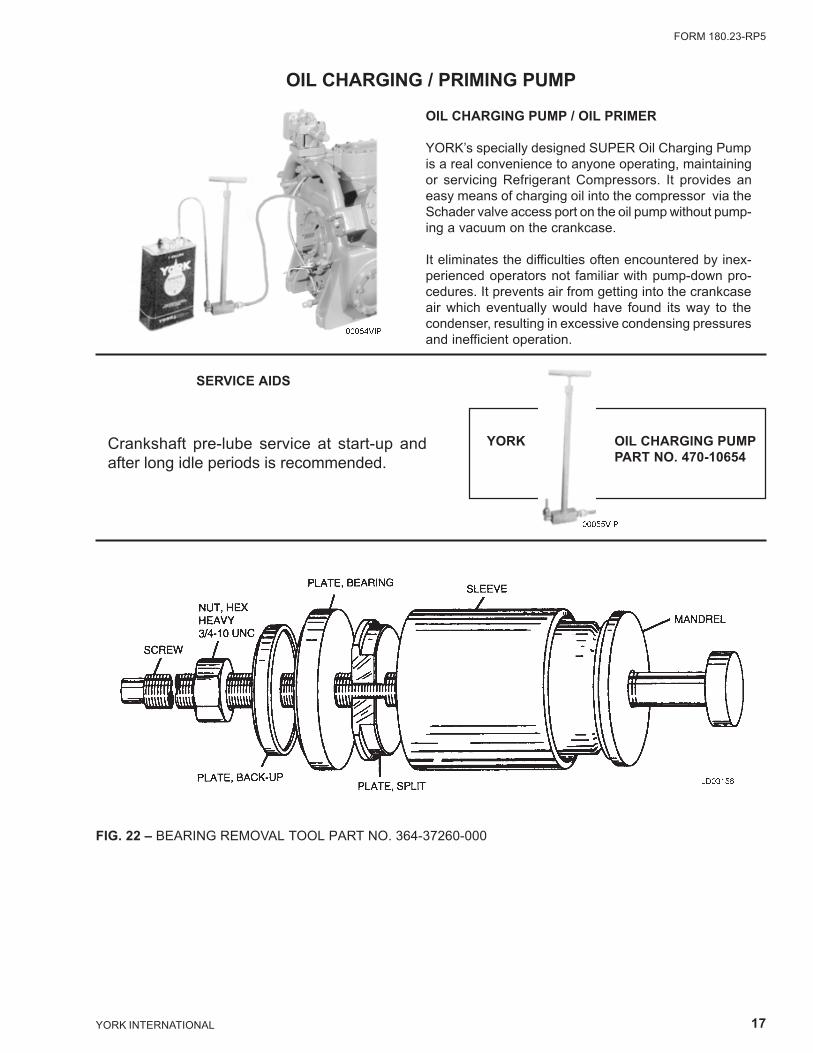
OIL CHARGING / PRIMING PUMP
OIL CHARGING PUMP / OIL PRIMER
YORK�s specially designed SUPER Oil Charging Pumpis a real convenience to anyone operating, maintainingor servicing Refrigerant Compressors. It provides aneasy means of charging oil into the compressor via theSchader valve access port on the oil pump without pump-ing a vacuum on the crankcase.
It eliminates the difficulties often encountered by inex-perienced operators not familiar with pump-down pro-cedures. It prevents air from getting into the crankcaseair which eventually would have found its way to thecondenser, resulting in excessive condensing pressuresand inefficient operation.
SERVICE AIDS
YORK OIL CHARGING PUMPPART NO. 470-10654
00054VIP
00055VIP
Crankshaft pre-lube service at start-up andafter long idle periods is recommended.
FIG. 22 � BEARING REMOVAL TOOL PART NO. 364-37260-000
LD03156

YO
RK
INT
ER
NA
TIO
NA
L1
8 MAINTENANCE REQUIREMENTS FOR YORK MODEL JK RECIPROCATING COMPRESSORS
NOTES:
A. PRE-LUBRICATION � To ensure long compressor life, pre-lubrication at start-up and after long idle periods of several months is recommended.This manual pre-lube is especially important on R-134a and R407C units that employ POE-type oil due to the polar nature of these oils. Thisis accomplished by attaching a hand pump to the core-type access port (schrader fitting) on the oil pump.
B. Run hours and starts must be recorded on all maintenance and repair records for warranty reimbursement.
� An Industry Certified Technician should perform this service. Proof of maintenance fulfillment may be required for warranty validation purposes.
* Reserved for any special site determined requirements.
1 For all models, maintain oil level no higher than the midpoint of the upper sight glass and no lower than the middle of the lower sight glass.2 Oil should be golden colored and relatively clear. If contamination is suspected, take an oil sample.3 On typical air conditioning applications, superheat should be 12° to 15°F.4 At idle, the crankcase oil heater should maintain a minimum oil temperature 15° to 30°F above ambient. During compressor operation, maximum
oil temperature is 160°F.5 Helical coil springs used in reciprocating compressor suction and discharge valve assemblies should be replaced every 5,000 hours when used on
normal chilled water (40° to 50°F LWT) air conditioning applications. Other applications that may operate at higher-pressure ratios such as lowtemp brine (20° to 39°F LWT), and units operating under high ambient conditions (ambient temps above 115°F) should have more frequentmaintenance intervals.
PROCEDURE MONTHLY QUARTERLY SEMI-ANNUALLYPER EVERY
APPLICATION * HOURS
Leak check X
Check oil level X1
Check oil appearance X2
Check compressor super heat X3
Record operating pressure,
temperatures, and motor current readingsX
Check oil temperatures X4
Change oil X2
Replace Suction / Discharge Springs � X5

FORM 180.23-RP5
19YORK INTERNATIONAL
ALABAMABirminghamYORK International Corp.(205) 987-0458
ARIZONAPhoenixYORK International Corp.(602) 220-9400
CALIFORNIALos AngelesYORK International Corp.(714) 897-0997San FranciscoYORK International Corp.(510) 426-1166
COLORADODenverYORK International Corp.(303) 649-1500
CONNECTICUTDanburyYORK International Corp.(203) 730-8100
FLORIDAMiamiYORK International Corp.(305) 389-9675TampaYORK International Corp.(381) 621-1323OrlandoYORK International Corp.(407) 444-2261
GEORGIAAtlantaYORK International Corp.(404) 925-0346
HAWAIIHonoluluYORK International Corp.(808) 596-0761
ILLINOISChicagoYORK International Corp.(708) 520-1910
INDIANAIndianapolisYORK International Corp.(317) 595-3050
KENTUCKYLouisvilleYORK International Corp,(502) 499-6020
LOUISIANANew OrleansYORK International Corp.(504) 464-6941
MARYLANDBaltimore/WashingtonYORK International Corp.(410) 720-6383
MASSACHUSETTSBostonYORK International Corp.(781) 769-7950
MICHIGANDetroitYORK International Corp.(810) 689-7277
MINNESOTAMinneapolisYORK International Corp.(612) 780-4446
MISSOURIKansas CityYORK International Corp.(816) 221-9675St. LouisYORK International Corp.(314) 770-0909
NEW JERSEYNewarkYORK International Corp.(908) 225-0606
NEVADALas VegasYORK International Corp.(702) 873-2200
NEW YORKBuffaloYORK International Corp.(716) 633-2172New YorkYORK International Corp.(212) 843-1602
NORTH CAROLINACharlotteYORK International Corp.(704) 598-0000GreensboroYORK International Corp.(336) 299-9675RaleighYORK International Corp.(919) 829-1700
OHIOCincinnatiYORK International Corp.(513) 489-8871ClevelandYORK International Corp.(216) 447-0696ColumbusYORK International Corp.(614) 841-5242
PENNSYLVANIAPhiladelphiaYORK International Corp.(610) 640-2320Pittsburgh(412) 364-6600YORKYORK international Corp.(717) 771-6561
SOUTH CAROLINAGreenvilleYORK International Corp,(803) 297-4822
TENNESSEEKingsportYORK International Corp.(615) 349-2450NashvilleYORK International Corp.(615) 833-9675
TEXASAustinYORK International Corp.(512) 458-4575DallasYORK International Corp.(214) 241-1219HoustonYORK International Corp.(713) 782-5200San AntonioYORK International Corp.(210) 496-6631
UTAHYORK International Corp.Salt Lake City(801) 261-1200
VIRGINIARichmondYORK International Corp.(804) 359-2600Newport News(804) 873-0362
WASHINGTONSeattleYORK International Corp,(206) 251-9145
CANADA Ottawa, Ontario Toronto, Ontario Laval, Quebec(613) 596-9111 (905) 890-6812 (514) 387-6000
YORK Applied Systems field office listing subject to change.
See us on the web at http://www.york.com/ for additional information.

Proud Sponsorof the 1998U.S. Olympic Team
36USC380
P.O. Box 1592, York, Pennsylvania USA 17405-1592 Subject to change without notice. Printed in USA
Copyright © by York International Corporation 1998 ALL RIGHTS RESERVED
Form 180.23-RP5 (1298)
Supersedes: 180.23-RP5 (698)