modelling of reactive distillation column by using …umpir.ump.edu.my/8871/1/cd8679 @ 61.pdf ·...
TRANSCRIPT
MODELLING OF REACTIVE DISTILLATION
COLUMN BY USING MOSAIC
CHIENG TIEW HING
Thesis submitted in partial fulfilment of the requirements
for the award of the degree of
Bachelor of Chemical Engineering
Faculty of Chemical & Natural Resources Engineering
UNIVERSITI MALAYSIA PAHANG
JUNE 2014
©CHIENG TIEW HING (2014)

IV
ABSTRACT
Due to many advantages of reactive distillation column (RD) comparing to traditional
method (reactors follows by distillation columns) in chemical synthesis, RD has been
drawing attentions of researchers around the world to explore its potentials in chemical
industries.
Modelling of RD can be made by many different modelling environments such as Matlab,
Fortran and so on. However, it is a time consuming process and a lot of effort will be
required in order to get the solutions of the model. Since the modelling is done by using
their own programming languages, it has the poor readability. Thus, users prone to make
the mistakes during coding and error identification will be difficult by using these
modelling software.
In this study of RD modelling, a new modelling environment called MOSAIC will
become the focus. MOSAIC is a web based modelling software and it introduces the new
modelling approach in order to overcome what it seems as insufficient places of other
modelling software. The key features of MOSAIC include modelling in the
documentation level, reuse of model elements, code generation for other modelling
environments and centralized cooperation on internet. (Kuntsche, Barz, Kraus, Arellano-
Garcia, & Wozny, 2011)
Modelling of reactive distillation column is based on the steady state equilibrium model.
It is assumed that the liquid and vapour phase behave ideally. Steady state equilibrium
model can be described by MESH equations. MESH equations are material balance
equation, phase equilibrium equation, summation equations and energy balance equation.
From the results, it can be seen that almost 100% conversion of reactants are achieved
with 94% of MTBE purity. The temperature profile shows that the temperature is
maintaining at 354K from condenser to feed stage. This is due to high purity of n-butene
in each stages. After feed stage, the temperature increases rapidly until it reaches highest
temperature of 424K at reboiler stage. This is caused by high mole fraction of MTBE
from condenser to reboiler stage.
MOSAIC makes the modelling possible even without the knowledge of programming
language. Latex documentary language is used by MOSAIC in documentation of
modelling equations. High readability of Latex allows modelling using MOSAIC to be
less errors and without much effort.

V
TABLE OF CONTENTS
SUPERVISOR’S DECLARATION ..................................................................................I
STUDENT’S DECLARATION ...................................................................................... II
ACKNOWLEDGEMENTS............................................................................................ III
ABSTRACT.................................................................................................................... IV
TABLE OF CONTENTS................................................................................................. V
LIST OF TABLES..........................................................................................................VI
LIST OF FIGURES .......................................................................................................VII
NOMENCLATURE .................................................................................................... VIII
Chapter 1: Introduction..................................................................................................... 1
1.1 Motivation and statement of problem ................................................................ 1
1.2 Objective and Scopes ......................................................................................... 2
1.3 The scopes of the research are ........................................................................... 2
Chapter 2: Literature Review............................................................................................ 3
2.1 Reactive Distillation Column............................................................................. 3
2.1.1. General Introduction of RD ............................................................................... 3
2.1.2. The advantages of RD........................................................................................ 4
2.1.3. The constraints of RD ........................................................................................ 5
2.2 MTBE................................................................................................................. 6
2.2.1. Background of MTBE production ..................................................................... 6
2.2.2. MTBE as Gasoline Additive .............................................................................. 7
2.2.3. MTBE Synthesis ................................................................................................ 7
2.3 Equilibrium Model of RD .................................................................................. 9
2.3.1. RD Models ......................................................................................................... 9
2.3.2. Mathematical Modelling of EQ Model ............................................................ 10
2.4 Kinetics model of MTBE Production .............................................................. 13
2.5 MOSAIC .......................................................................................................... 14
2.5.1. Introduction of MOSAIC ................................................................................. 14
2.5.2. 4 Main Features of MOSAIC........................................................................... 14
2.6 Summary .......................................................................................................... 15
Chapter 3: Methodology ................................................................................................. 16
3.1 Conditions of MTBE Production using RD ..................................................... 16
3.1.1. Assumptions of Modelling............................................................................... 16
3.1.2. Conditions of MTBE Synthesis ....................................................................... 17
3.2 Procedure of RD Modelling using MOSAIC................................................... 18
Chapter 4: Results and Discussion.................................................................................. 29
4.1 Results & Discussion ....................................................................................... 29
4.2 Comparison with Expected Results ................................................................. 30
4.3 Comparison between MOSAIC and other modelling environments ............... 31
Chapter 5: Conclusion .................................................................................................... 33
References....................................................................................................................... 34
Appendices...................................................................................................................... 35

VI
LIST OF TABLES
Table 1: The feed specifications of methanol and butenes & operating conditions for
MTBE synthesis (Nijhuis et al., 1993) ........................................................................... 17
Table 2: Comparison of results between proposed model and Nijhuist's model ............ 30
Table 3: Comparison of MOSAIC with two groups of modelling tools ........................ 31

VII
LIST OF FIGURES
Figure 1:(a) Typical configuration of a conventional process consisting of a reactor
followed by a distillation train. (b) The reactive distillation configuration. (Stichlmair &
Frey, 1999)........................................................................................................................ 3
Figure 2: The bar chart shows the MTBE & ethanol production from 1992 until 2002 in
US (EIA, 2003a) ............................................................................................................... 6
Figure 3: Schematic Representation of a Reactive Distillation Columns (Murat,
Mohamed, & Bhatia, 2003) ............................................................................................ 10
Figure 4: Column Configuration and Feed Specifications for MTBE synthesis (Murat et
al., 2003) ......................................................................................................................... 16
Figure 5: Procedure of modelling using MOSAIC......................................................... 18
Figure 6: Creating of notation......................................................................................... 19
Figure 7: Creating of equations ...................................................................................... 20
Figure 8: Creating of functions....................................................................................... 21
Figure 9: Adding of modelling equations ....................................................................... 22
Figure 10: Adding of functions....................................................................................... 23
Figure 11: Adding of functions applications .................................................................. 23
Figure 12: Setting of input variables............................................................................... 24
Figure 13: Preview of equation system........................................................................... 25
Figure 14: Setting of indexing number ........................................................................... 26
Figure 15: Preview of all modelling equations and functions after indexing ................. 26
Figure 16: Variable specification.................................................................................... 27
Figure 17: Code generation............................................................................................. 28
Figure 18: Temperature versus Stage number ................................................................ 29
Figure 19: Liquid mole fraction of each components versus Stage number .................. 29

VIII
NOMENCLATURE
a Activity -
F Feed molar flow rate mol/s
H Enthalpy J/mol
L Liquid molar flow rate mol/s
Mj Molar liquid hold up on
stage j
mol/s
P Total pressure Pa
Po Saturated vapour pressure Pa
R Reaction rate mol/s
r number of reactions -
t time s
T Temperature K
V Vapour molar flow rate mol/s
W Catalyst weight kg
x Liquid composition -
y Vapour composition -
z Feed composition -
Greek letters
δ Parameter for reaction
occurrence on stage j (0 or
1)
-
ϕ Fugacity coefficient -
γ Activity coefficient -
Subscripts
i Component number
j Stage number
Superscripts
c Total number of components
List of abbreviations
EQ Equilibrium model
MeOH Methanol
MTBE Methyl tert-butyl ether
NEQ Non-equilibrium model
RD Reactive distillation
1
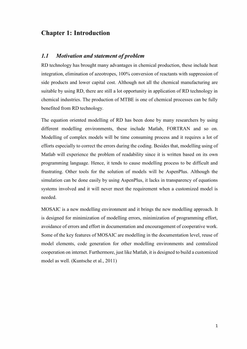
Chapter 1: Introduction
1.1 Motivation and statement of problem
RD technology has brought many advantages in chemical production, these include heat
integration, elimination of azeotropes, 100% conversion of reactants with suppression of
side products and lower capital cost. Although not all the chemical manufacturing are
suitable by using RD, there are still a lot opportunity in application of RD technology in
chemical industries. The production of MTBE is one of chemical processes can be fully
benefited from RD technology.
The equation oriented modelling of RD has been done by many researchers by using
different modelling environments, these include Matlab, FORTRAN and so on.
Modelling of complex models will be time consuming process and it requires a lot of
efforts especially to correct the errors during the coding. Besides that, modelling using of
Matlab will experience the problem of readability since it is written based on its own
programming language. Hence, it tends to cause modelling process to be difficult and
frustrating. Other tools for the solution of models will be AspenPlus. Although the
simulation can be done easily by using AspenPlus, it lacks in transparency of equations
systems involved and it will never meet the requirement when a customized model is
needed.
MOSAIC is a new modelling environment and it brings the new modelling approach. It
is designed for minimization of modelling errors, minimization of programming effort,
avoidance of errors and effort in documentation and encouragement of cooperative work.
Some of the key features of MOSAIC are modelling in the documentation level, reuse of
model elements, code generation for other modelling environments and centralized
cooperation on internet. Furthermore, just like Matlab, it is designed to build a customized
model as well. (Kuntsche et al., 2011)
2
1.2 Objective and Scopes
The objective of the research is to
Explore the modelling of RD for MTBE production by using MOSAIC
1.3 The scopes of the research are
Modelling of equilibrium(EQ) model of RD by using MOSAIC based on the given
parameters of MTBE production
Validation of the modelled RD with results from literature.
Comparison between MOSAIC and other modelling environments.

3
Chapter 2: Literature Review
2.1 Reactive Distillation Column
2.1.1. General Introduction of RD
Although reactive distillation column (RD) was invented in 1921, the industrial
application is only started to after 1980’s. (Agreda, Partin, & Heise, 1990) RD consists
of both reactor and distillation column under a single vessel. It have brought many
advantages to chemical production especially for its high conversion and selectivity.
Production of MTBE is one of chemicals that can be fully benefited from RD technology.
However, not all the chemical production are suitable to use RD in manufacturing.
The introduction of in-situ reaction with distillation in a single vessel leads to the complex
interactions between vapour- liquid equilibrium, vapour-liquid mass transfer, intra-
catalyst diffusion (for heterogeneously catalysed process) and chemical kinetics. (Taylor
& Krishna, 2000) This makes the design of these systems to be difficult.
Figure 1:(a) Typical configuration of a conventional process consisting of a reactor
followed by a distillation train. (b) The reactive distillation configuration. (Stichlmair &
Frey, 1999)

4
From the Fig. 1(a), it shows the traditional method of chemical synthesis where the
chemical reaction occurs in reactor and then the products are separated by distillation
train. If the azeotropes are formed by the products, it will cause the separation of chemical
components to be difficult and the distillation train will far more complicated than one
shown in the figure above.
From the Fig. 1(b), the RD column consists of a reactive section in the middle with
nonreactive rectifying and stripping sections at the top and bottom. For a properly
designed RD column, virtually 100% conversion can be achieved. (Taylor & Krishna,
2000)
2.1.2. The advantages of RD
The RD is quite beneficial especially for the exothermic reaction. MTBE production is
one of the exothermic reaction. The heat integration allows fully taking advantage of heat
energy released from the chemical reaction. The heat released will be used in vaporization
and reduce the duty of the reboiler. This will further decrease the risk of runaway reaction.
In addition, the formation of azeotropes can be avoided in RD. For the case of MTBE, by
using traditional method where the reactor followed by distillation columns, extra 10%
of methanol is required to feed into the reactor in order to reduce the mainly isobutylene
dimmers by-product formation. (Elkanzi, 1996) The MTBE produced forms the
azeotropes with the methanol and isobutylene. The reactant mixture leaving the reactor
forms three minimum azeotropes (Taylor & Krishna, 2000) and it causes the separation
of the mixture to be difficult. However, with the RD concept, it allows some of the
azeotropes just “reacting away”. (Doherty & Buzad, 1992)
Moreover, the conversion of reactants can nearly achieve 100% with the suppression of
the side reactions in RD. Thus, the selectivity of product is high. The limitation of
chemical equilibrium can be overcome by RD by removing the product from reacting
mixture. Therefore, the complete conversion can be achieved with the shifting of
equilibrium to the right. For the case of MTBE, nearly 100% of conversion of isobutylene
and methanol can be achieved along with suppression of the formation of the unwanted
dimethyl ether by using RD. (Sundmacher, 1995)

5
Furthermore, the capital cost of RD in industrial production is lower than conventional
method. The high number of required distillation columns can be avoided by using RD.
The reduction of required pumps, instruments and piping also further decrease the capital
cost. (Mohammed, 2009)
2.1.3. The constraints of RD
Although RD is a new technology and brings many advantages to the production of
MTBE, not all the chemicals manufacturing are suitable by using RD. There are few
constraints of RD. (Towler & Frey, 2002) The constraints could be the reactants and
products may not have suitable volatility to maintain high concentration of reactants and
low concentration of products in the reaction zone. Moreover, if the residence time is too
long, a large column size and large tray hold-ups will be needed. Therefore, it may be
more economical to use conventional method of reactor followed by distillation columns.
Besides that, the optimum temperature and pressure of the reaction may not suitable under
the optimal conditions of distillation. Furthermore, scale up to large flow rate is not
suitable by using RD due to liquid distribution problems in packed RD columns.

6
2.2 MTBE
2.2.1. Background of MTBE production
In 1998, the worldwide production MTBE had achieved its records high with 6.6 billion
gallons annually (Ahmed, 2001), with the US occupied the large portion of it, around 4.3
billion gallons per year. Besides that, MTBE was considered as one of the top 50
chemicals produced in the world. (WHO, 1998) However, the use of MTBE in US as
gasoline additive gradually replaced by the ethanol, as the legislation favouring the
ethanol. This is due the underground water and soil contamination caused by MTBE.
(EIA, 2003b) It is estimated to cost 1 billion to 30 billion dollars to clean the aquifers and
municipal water supplies and replacing leaky underground oil tanks. (Napoli, 2004)
Nevertheless, the demand of MTBE is still growing in Asia as ethanol is less subject to
subsidies.
Figure 2: The bar chart shows the MTBE & ethanol production from 1992 until 2002 in
US (EIA, 2003a)
Despite legislation of US in many states gradually phase out the use of MTBE as gasoline
addictive, worldwide MTBE production is still remains constant due to the growth in
Asian markets. The information from GIA shows that global market MTBE is expected
to reach 19.2 million tons by the year 2017, this is driven primarily by the increased
demand from developing countries such as Asia, particularly China, Middle East, and
Latin America. The increasing automobile ownership in these countries and use of MTBE
7
as an additive to improve quality of gasoline is expected to fuel consumption of MTBE.
(GIA, 2011)
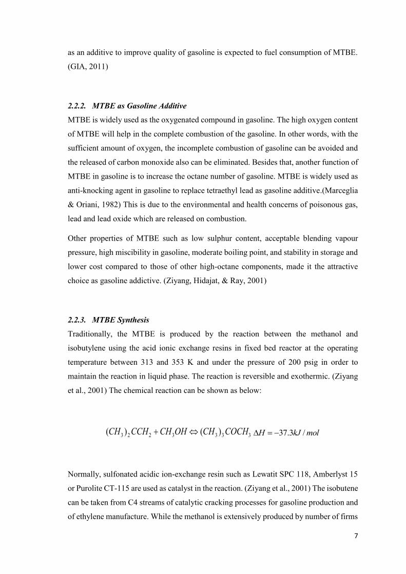
2.2.2. MTBE as Gasoline Additive
MTBE is widely used as the oxygenated compound in gasoline. The high oxygen content
of MTBE will help in the complete combustion of the gasoline. In other words, with the
sufficient amount of oxygen, the incomplete combustion of gasoline can be avoided and
the released of carbon monoxide also can be eliminated. Besides that, another function of
MTBE in gasoline is to increase the octane number of gasoline. MTBE is widely used as
anti-knocking agent in gasoline to replace tetraethyl lead as gasoline additive.(Marceglia
& Oriani, 1982) This is due to the environmental and health concerns of poisonous gas,
lead and lead oxide which are released on combustion.
Other properties of MTBE such as low sulphur content, acceptable blending vapour
pressure, high miscibility in gasoline, moderate boiling point, and stability in storage and
lower cost compared to those of other high-octane components, made it the attractive
choice as gasoline addictive. (Ziyang, Hidajat, & Ray, 2001)
2.2.3. MTBE Synthesis
Traditionally, the MTBE is produced by the reaction between the methanol and
isobutylene using the acid ionic exchange resins in fixed bed reactor at the operating
temperature between 313 and 353 K and under the pressure of 200 psig in order to
maintain the reaction in liquid phase. The reaction is reversible and exothermic. (Ziyang
et al., 2001) The chemical reaction can be shown as below:
3333223 )()( COCHCHOHCHCCHCH molkJH /3.37
Normally, sulfonated acidic ion-exchange resin such as Lewatit SPC 118, Amberlyst 15
or Purolite CT-115 are used as catalyst in the reaction. (Ziyang et al., 2001) The isobutene
can be taken from C4 streams of catalytic cracking processes for gasoline production and
of ethylene manufacture. While the methanol is extensively produced by number of firms

8
from inexpensive natural gas and other carbon sources. (Mitani, Keller, Bunton, Rinker,
& Sandall, 2002)

9
2.3 Equilibrium Model of RD
2.3.1. RD Models
There are several models in designing of RD. (Richard Baur, 2000) They are listed as
follows:
1. Steady-state equilibrium (EQ) stage model
2. Dynamic EQ stage model
3. Steady-state EQ stage model with stage efficiencies
4. Dynamic EQ stage model with stage efficiencies
5. Steady-state non-equilibrium (NEQ) stage model, where the interphase mass
transfer is described by rigorous Maxwell-Stefan diffusion equations
6. Dynamic NEQ stage model
7. Steady-state NEQ cell model, developed by Higler (1999), in order to account for
staging of the vapour and liquid phases during cross-current contacting on a
distillation tray
In this study, modelling of RD by using MOSAIC will be based on steady state EQ model.
In equilibrium (EQ) stage model, the vapour and liquid phases are assumed to be in
thermodynamic equilibrium. (R Baur, Higler, Taylor, & Krishna, 2000)

10
Figure 3: Schematic Representation of a Reactive Distillation Columns (Murat,
Mohamed, & Bhatia, 2003)
2.3.2. Mathematical Modelling of EQ Model
The first step of modelling begins with mathematical modelling by formulation of
equations to describe processes occurring in RD at the steady state. These formulated
equations or just MESH equations will be required in finding solution of the model. The
letters of MESH stand for material balance equations, phase equilibrium equations,
summation equations and heat balance equations. The MESH equations shown below are
modified from work of Murat et al. (2003).

11
Material balance equations
The material balance of every stages of RD can be represented by equation as follow:
Overall material balance
jjjjjjj
jRLVVLF
dt
dM 11
Components material balance
R
r
rjrijijjijjijjijjijj
ijjrvxLyVyVxLzF
dt
xdM
1
,,,11,11,,,
,
Since the model is assumed as steady state, and thus the derivative of material balance
will be equal zero. Both j and i are subscripts to represent the stages numbers and
components respectively. F represents feed flow rate, L represents liquid flow rate then
V will represent vapour flow rate. x and y are the mole fraction of liquid and vapour
respectively.
Furthermore, for integrated reactive part of equation, r represents the reaction rate and v
represents the stoichiometry of chemical components. The value of δ will be either 0 or
1 to decide whether reaction occurring at the stages or not.
Phase equilibrium equations
P
xPy
o
Phase equilibrium relation equation describes the relationship between liquid mole
fraction and vapour mole fraction of chemical components when vapour and liquid at
equilibrium state. For the ideal condition, the value of activity coefficient, γ and fugacity,
ϕ will be equal to 1. Saturated vapour pressure, Po can be calculated using of Antoine
equation and P is pressure of reactive distillation column.

12
Summation equations
0.1, c
i
ijx (Liquid phase)
0.1, c
i
ijy (Vapour phase)
From the summation equation, it states that sum of mole fraction of each components in
liquid phase and vapour phase of each stages will be equal to 1.
Enthalpy balance equations.
The energy balance of each stages of RD can be described by equation as follow
rj
R
r
R
rjj
V
jj
V
jj
L
jj
F
j
jrHHVHVHLHF
dt
dH,
1
,1111
Again, for the steady state, the derivative of energy balance will be equal to zero. For the
reactive part of the equation, ΔH is enthalpy change of chemical reaction, r is the rate of
reaction and δ will decide whether the reaction taking place at each stages or not. For the
case RD modelling for MTBE production, it assumes only a single reaction, and thus the
summation of enthalpy change can be ignored.

13
2.4 Kinetics model of MTBE Production
For the production of MTBE, the kinetics model is obtained from work of Rehfinger and
Hoffmann (1990) . The activity based rate model is shown as follow:
MeOH
ieq
MTBE
i
MeOH
i
IB
i
fj
aK
a
a
aWqkr
2
where
iii xa
)11110
exp(1067.3 12
Tk f
TfKeq exp284
4
0
4
6
3
0
3
5
2
02403
0
2
0
1 ln11
TTATTATTATTAT
TA
TTATf
From the equation, W is weight of catalyst of each stages. q is the amount of acid groups
on the resin per unit mass with value of 4.9 equiv/kg. The activity of each components is
the product of its activity coefficient and liquid mole fraction. kf is reaction rate constant
and Keq is equilibrium constant.
T0 = 298.15 K
A1 = - 1.49277×10³ K
A2 = - 77.4002
A3 = 0.507563 K-1
A4 = 9.12739×10⁻⁴ K-2
A5 = 1.10649×10⁻⁶ K-3
A6 = - 6.27996×10⁻¹⁰ K-4

14
2.5 MOSAIC
2.5.1. Introduction of MOSAIC
MOSAIC is a web-based modelling software which brings the new modelling approach.
It makes the modelling possible without knowing the programming language of
modelling. It is designed for minimization of modelling errors, minimization of
programming effort, avoidance of errors and effort in documentation and encouragement
of cooperative work. (Kuntsche et al., 2011)
2.5.2. 4 Main Features of MOSAIC
One of the important features of MOSAIC is modelling at the documentation level. It
means that MOSAIC can make the modelling at documentation level without any
paperwork. The equations can be documented easily by MOSAIC using Latex
documentary language. By using Latex, the documented equations have the same
readability as documentation level. In addition, modelling can be done by MOSAIC even
without knowing of modelling programming languages.
Besides that, MOSAIC is also designed for reuse of model elements effectively. In
MOSAIC, modelling is done by creating of objects separately. These objects include
notation object, equation objects, function objects, equation system object, evaluation
object and parameter object. Each objects can be reused by another models. Thus, it will
reduce the effort of modelling.
The next important features of MOSAIC is code generation for other modelling
environments. MOSAIC itself can be a code generator and solver. However, MOSAIC is
not designed to be a full solver as complicated models cannot solved by using MOSAIC.
MOSAIC has more complete support of code generation for other modelling
environments.
Moreover, MOSAIC also has the feature of centralized cooperation on internet. It allows
users to share their models easily. The shared model can be read or write by another user
on internet.

15
2.6 Summary
By introduction of RD technology in chemical industries, it brings numerous advantages
by comparing with traditional chemical synthesis method. MTBE production is one of
the chemical synthesis that can be fully benefited from RD technology. Those advantages
include heat integration, elimination of azeotropes, 100% conversion of reactant with
suppression of side products and the lower capital cost.
For the next chapter, procedure of modelling using MOSAIC based on the given
parameters of MTBE production will be discussed.

16
Chapter 3: Methodology
3.1 Conditions of MTBE Production using RD
Figure 4: Column Configuration and Feed Specifications for MTBE synthesis (Murat et
al., 2003)
3.1.1. Assumptions of Modelling
In this modelling, it was assumed that MTBE synthesis system only consists of main
components, namely methanol, isobutylene, MTBE, and n-butene. However, in the actual
situation, there are totally a minimum of 12 components with reactive components of
methanol, isobutene and MTBE involve in the MTBE synthesis. Moreover, the inert C4
components can be assumed to be represented by n-butene since they have quite similar
physical and chemical properties. The small quantities of by-products can be regarded as
negligible.

17
3.1.2. Conditions of MTBE Synthesis
It is assumed that the production rate of MTBE to be 197 mol/s or 500,000 metric
tons/year. 6400 kg of catalyst is used for 8 reactive trays with amount of 800kg catalyst
each reactive tray. The reactive trays are located in the middle of column from the stage
3 until stage 10. There are totally 17 stages with condenser as stage 0 and partial reboiler
as stage 16. The operating pressure is 11 bar or 10.87 atm. The reflux ratio is set to 7.
There are two feed streams, methanol feed stream and mixed butenes feed stream with a
small stoichiometric excess of methanol. (Nijhuis, Kerkhof, & Mak, 1993)
The feed synthesis specifications, column configuration and operating conditions for
MTBE synthesis are summarized in the table below:
Table 1: The feed specifications of methanol and butenes & operating conditions for
MTBE synthesis (Nijhuis et al., 1993)
Feed Streams Methanol Butenes Units
Feed rate 206 549 mol/s
Phase Liquid Vapour
Temperature 320 350 K
Pressure 11 11 bar
Feed stage 10 10
xMeOH 1.0 0.000
xIB 0.0 0.356
xn-butene 0.0 0.644
Number of Stages,
N
17
Column Pressure, P 11 bar
Catalyst Weight, W 6400 kg
Reflux Ratio, r 7
Bottom Flow, B 197 mol/s

18
3.2 Procedure of RD Modelling using MOSAIC
The process of RD modelling by using MOSAIC can be summarized by flowchart as
shown below:
Figure 5: Procedure of modelling using MOSAIC
Creating of notation object
Creating of equation objects
Creating of function objects
Creating of equation system
Creating of evaluation object
Creating of parameter object
Code generation and evaluation