modelling of defects and failure in composites - stephen hallett.pdf · · 2016-02-23modelling of...
TRANSCRIPT

Modelling of defects and failure in composites
Prof. Stephen Hallett
www.bris.ac.uk/composites

Virtual Testing
Coupons
Generic features
Specific features
Sub-components
Components
Test Analysis
Current Future
Test Analysis
Test backed up by Analysis Analysis backed up by Test

Defects and Features
• Composites’ structural properties are influenced
by ply scale features in the geometry
• The as-manufactured component varies from the
design intent
• Knowledge of the effect of defects is important
for :
– Certification
– Design process to inform stress allowables
– NDT and quality control for sentencing of defects
– Test work to design representative specimens
• Large range of possible defects means testing of
all cases is not possible – development of
hi-fidelity modelling tools

As-Manufactured Virtual Composites
• Process
modelling
• Formation
of defects
• Influence of
process
parameters
• Advanced
failure
prediction
• High fidelity
simulations
• Effect of defects
• Complex loading
• As
manufactured geometry
• Mesh creation
• Acceptance limits
• Inspection limits
6 mm
Effect of wrinkles
Ply drops and embedded delaminations
Textile composites
Process modelling
FE models from NDTdata

• Out of plane waviness
– Critical defect in terms of reduction in
compressive strength
• Gaps and overlaps
– Caused by automated tape laying process
• Delamination defects
– E.g. small inclusions or imperfections during layup
– Simplified specimen used, combined with ply drops
– Low velocity impact damage
• Voids and Porosity
Defect Types
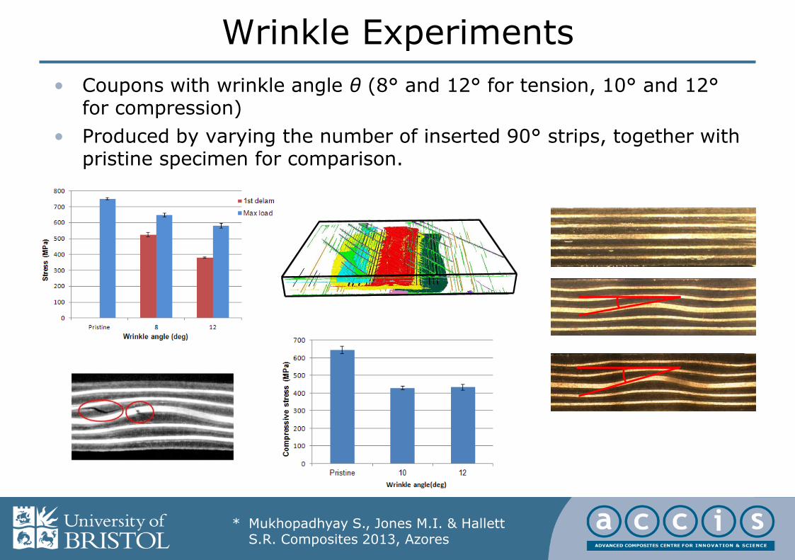
Wrinkle Experiments
• Coupons with wrinkle angle θ (8° and 12° for tension, 10° and 12°for compression)
• Produced by varying the number of inserted 90° strips, together with pristine specimen for comparison.
0
50
100
150
200
250
300
350
400
0 0.5 1 1.5 2
Ten
sile
str
ess
(M
Pa)
Crosshead displacement (mm)
* Mukhopadhyay S., Jones M.I. & Hallett S.R. Composites 2013, Azores

Wrinkle Modelling
• Modelled with ply-by-ply hi-fidelity analysis in Abaqus/explicit
• Cohesive interface elements for delamination
• In-plane damage models for matrix cracking and fibre failure
6 mm
+45°
90°
-45°
0°
Compressive stress at final failure
* Mukhopadhyay S., Jones M.I. & Hallett S.R. Composites 2013, Azores

A
A’
B
B’
Hi-fidelity Gaps & Overlaps Modelling
preprocessor1 preprocessor2 preprocessor3 preprocessor4
A
A’
B
B’
A
A’
B
B’
preprocessor5
AA’
Improved Ply waviness by Spline curve interpolating in X, Y direction-1st derivative of waviness is continuous at every node
• Internal geometry of plies and Gaps & Overlaps features is highly complex
• Requires custom tools for generating models with Gaps & Overlaps
* Li X. et al, ICMAC, 2015, Bristol

Gaps & Overlaps Models
• Cross-section images
A
A’
A
A’
A
A’
* Li X. et al, ICMAC, 2015, Bristol

Compression Testing of Gaps and Overlaps
* Li X. et al, ICMAC, 2015, Bristol

Delaminations and Ply-drops
• Ply-drops are an unavoidable feature in variable thickness laminates
• Simplified specimen developed to examine failure
• Hi-fidelity modelling with cohesive elementsused for assessment
• Local geometry has a strong effect on strength
– Ply waviness from layup
– Shape of resin pocket at ply termination
– Manufacturing defects leading to small delaminations at the end of ply terminations
* Kawashita L et al, ICCM18, 2011, Jeju Island

Ply-Level Meshing Algorithms
• As-manufactured geometries and internal features captured initially by an image-based meshing technique
• Virtual testing can then be used to augment the building block approach –here considering a wide range of delamination defect locations
* Kawashita L et al, ICCM18, 2011, Jeju Island

Virtual Testing of Defects• Example: 4mm long delaminations (NDT detection threshold) introduced
near ply terminations
• Automatic mesh generation, job submission & post-processing in a Linux cluster; hundreds of runs completed overnight
Runtime for each
slice model:
20-40 min*
*previous generation
8-core HPC node
01a
defects
resin
pockets
01b 02a 02b
03a 03a 04a 04a
05a 05a 06a 06a
07a 07a 08a 08a
* Kawashita L et al, ICCM18, 2011, Jeju Island

Virtual Testing of Defects: Static Strength
• Maximum strength knockdown, critical defect locations and respective delamination mode-mixities identified
• Methodology validated against experiments for various thickness and taper angles
worst
defect
location
pristine
worst defect
location
02a
Symmetric
specimens
* Kawashita L et al, ICCM18, 2011, Jeju Island

Laminated Composite Plate
Supporting Window
Indenter/ Impactor
m n
b a
d
X Y
Z
90o
0o
-45o
45o
0
1
2
3
4
5
6
0 1 2 3 4 5
Load (
kN
)
Time (ms)
FS-6J
FS-4J
* Hallett S.R. and Sun X., ICILLS,2014, Cape Town
Impact Damage
• Low velocity impact is well known for introducing delamination damage (BVID)
• This dramatically reduces the Compression After Impact (CAI) strength
• Hi-fidelity models are able to accurately predict impact damage in the form of delamination, matrix cracks and fibrefailure

• Impact induced damage can be input into models either from simulation or test data
• In-plane loading of damaged panel caused growth of critical delaminations and ultimate failure
• Models can be used to predict failure and also study mechanisms in detail as well as effect of layup etc.
CAI Strength

Voids
• Modelling of voids is not as well advanced as other defect types
• More challenging because the exact mechanism of failure from voids is not well understood
• Most work considers the knock-down due to global void volume fraction, but not local void morphology
• Current work is focussed on the detailed understanding of failure from voids to embed into future models
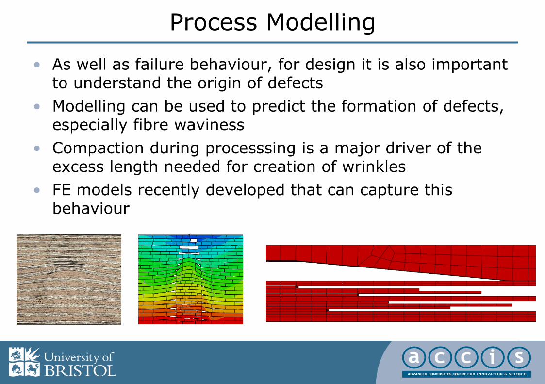
Process Modelling
• As well as failure behaviour, for design it is also important to understand the origin of defects
• Modelling can be used to predict the formation of defects, especially fibre waviness
• Compaction during processsing is a major driver of the excess length needed for creation of wrinkles
• FE models recently developed that can capture this behaviour

Future Challenges
• How to model a full component when a feature model takes >500,000 elements?– Homogenised models
– Shell elements
• Bridging the length scales– Micro-meso
– Meso-macro
– Multi-scale models
• Modelling the as manufactured condition– Statistical variance
• New materials and manufacturing processes– 3D woven textiles
– Fibre placement
• Computational resource– Very large numbers of CPU
– Used efficiently
• Advanced Numerical Methods– XFEM