modelling of a rope-free passenger transportation system
TRANSCRIPT

Modelling of a Rope-Free Passenger Transportation System for Active Cabin Vibration Damping
Jonas Missler1, Thomas Ehrl2, Benedikt Meier2, Stefan Kaczmarczyk3 and Oliver Sawodny1
1Institute for System Dynamics (ISYS), University Stuttgart, Waldburgstr. 19, 70563 Stuttgart, Germany, Email: [email protected], Email: [email protected]
2thyssenkrupp Elevator Innovation GmbH, Robert-Bosch-Straße 5, 72124 Pliezhausen, Germany, Email: [email protected], Email:
3School of Science and Technology, University of Northampton, St. George’s Avenue, Northampton NN7 3NG, UK, Email: [email protected]
Keywords: Dynamic Modelling, Multi-Body System, Vibration Damping, Control Engineering.
Abstract. Conventional vertical passenger transportation is performed by lifts. Conventional traction-drive electrical lifts use ropes to transfer the rotational motion of an electrical motor into a vertical motion of the cabin. The vertical passenger transportation system discussed in this paper does not use any ropes, the motor directly provides a driving force, which moves the cabin. This new propulsion is realized through an electrical linear motor. The use of the linear motor requires a new design of the passenger transportation system (PTS), which includes reducing the weight of the car through lightweight construction. The reduced stiffness of the lightweight design renders the construction more vulnerable to vibrations. In order to improve ride quality of the transportation system it is necessary to develop new concepts to damp the vibrations. One way to increase stiffness characteristics of the system is to introduce active damping components to be used alongside passive damping components. It is essential to derive a dynamic model of the system in order to design and also later control these damping components in the best possible way. This paper describes the fundamental steps undertaken to derive a dynamic model for designing and controlling active damping components for the new type of vertical PTS. The model is derived as a Multi-Body System (MBS), where the connections between the bodies are modelled as spring damper elements. The derivation of the MBS is demonstrated on a transportation system, consisting of three main components: a sledge, holding the rotor of the linear motor; a mounting frame, which is used to provide support for the cabin; and the actual cabin. The modelling of the propulsion system, thus the electrical part of the PTS, will not be the focus of this work.
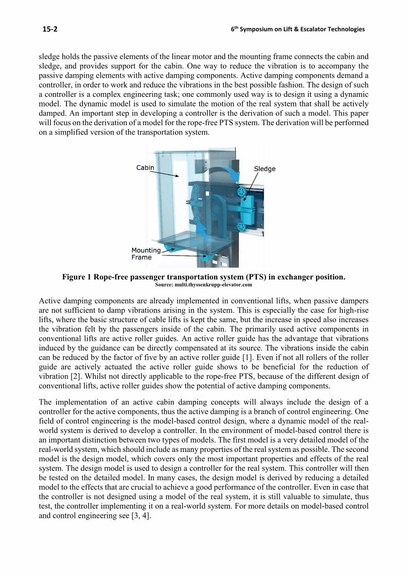
1 INTRODUCTION The novel way of lift designs is PTS without ropes, where a linear motor directly provides the vertical motion. The rope-free propulsion offers several benefits, like vertical and horizontal travel, the possibility of multiple lift cars that may ride in a single shaft and the reduction in construction space. The ability of horizontal movement of the PTS allows the connection of several lift shafts and hence enables the design of more complex lift shaft networks. A disadvantage of the new propulsion is the lesser weight that can be carried, therefore a lightweight design of the PTS system is required. Lightweight construction render systems more susceptible to vibrations, due to the reduction in stiffness. In general the riding comfort of passengers in lifts decreases in the presence of vibrations, the vibrations should therefore be kept at an acceptable level. In conventional lifts vibrations have been reduced by passive damping elements that are placed in the mounting frame around the exterior of the cabin. This construction decouples the lift cabin from the rest of the car and leads to an improved riding quality for the passengers. The new structure of the rope-free PTS omits the mounting frame around the cabin, due to the new propulsion. The high passenger comfort of conventional lifts must be kept for the new transportation system and therefore it is essential to develop a new damping concept that fits the new requirements. The new design of the rope-free PTS is shown in Fig. 1, it consists of three main parts: a sledge, a mounting frame and the cabin. The
15-2 6th Symposium on Lift & Escalator Technologies
sledge holds the passive elements of the linear motor and the mounting frame connects the cabin and sledge, and provides support for the cabin. One way to reduce the vibration is to accompany the passive damping elements with active damping components. Active damping components demand a controller, in order to work and reduce the vibrations in the best possible fashion. The design of such a controller is a complex engineering task; one commonly used way is to design it using a dynamic model. The dynamic model is used to simulate the motion of the real system that shall be actively damped. An important step in developing a controller is the derivation of such a model. This paper will focus on the derivation of a model for the rope-free PTS system. The derivation will be performed on a simplified version of the transportation system.
Figure 1 Rope-free passenger transportation system (PTS) in exchanger position.
Source: multi.thyssenkrupp-elevator.com
Active damping components are already implemented in conventional lifts, when passive dampers are not sufficient to damp vibrations arising in the system. This is especially the case for high-rise lifts, where the basic structure of cable lifts is kept the same, but the increase in speed also increases the vibration felt by the passengers inside of the cabin. The primarily used active components in conventional lifts are active roller guides. An active roller guide has the advantage that vibrations induced by the guidance can be directly compensated at its source. The vibrations inside the cabin can be reduced by the factor of five by an active roller guide [1]. Even if not all rollers of the roller guide are actively actuated the active roller guide shows to be beneficial for the reduction of vibration [2]. Whilst not directly applicable to the rope-free PTS, because of the different design of conventional lifts, active roller guides show the potential of active damping components.
The implementation of an active cabin damping concepts will always include the design of a controller for the active components, thus the active damping is a branch of control engineering. One field of control engineering is the model-based control design, where a dynamic model of the real-world system is derived to develop a controller. In the environment of model-based control there is an important distinction between two types of models. The first model is a very detailed model of the real-world system, which should include as many properties of the real system as possible. The second model is the design model, which covers only the most important properties and effects of the real system. The design model is used to design a controller for the real system. This controller will then be tested on the detailed model. In many cases, the design model is derived by reducing a detailed model to the effects that are crucial to achieve a good performance of the controller. Even in case that the controller is not designed using a model of the real system, it is still valuable to simulate, thus test, the controller implementing it on a real-world system. For more details on model-based control and control engineering see [3, 4].

Modelling of a Rope-Free Passenger Transportation System for Active Cabin Vibration Damping 15-3
A commonly used technique to derive a dynamic model of a mechanical system is by using Multi-Body-System (MBS) techniques. The method of MBS is especially applicable for rigid systems which experience large rotational and translational displacements. The key point of modelling via MBS is to divide the real-world system into several bodies and use connection elements, like joints, springs and dampers to connect these bodies. The technique of MBS is an internationally standardised method for the derivation of an idealised dynamic model of a mechanical system and is a part of the classical mechanical engineering [5]. The dynamics of the MBS can also serve as a basis for vibration analysis and model-based control design [6]. The application of MBS for the active rope-free PTS is therefore a natural one; the separation in rigid bodies’ results from the three main parts of the lift car. Another advantage of MBS is their extensibility. If the flexibility of a body is crucial to the overall dynamic behaviour of a system this body can be replaced by a flexible body, resulting in a MBS [7].
The goal of this paper is to presents the modelling for active cabin vibration damping on the example of a simplified version of the rope-free PTS. The following chapter will give a brief outline of the expected vibrations in the environment of a rope-free transportation system. The third chapter will give a short overview of the basic steps needed to derive a MBS and also give a selection of modelling elements used in the context of MBS. The succeeding chapters will give a short overview over the complex model and display the derivation of the dynamic model on a two-dimensional simplified version of the passenger transportation system. The influence of periodic imperfections in the guide rails on the cabin will also be simulated with the simplified model. In the conclusion, an outlook over the further steps in the design of active vibration damping will be given.
2 VIBRATIONS The aim of active cabin damping is the improvement of the passenger’s riding comfort. One crucial step for an improvement of the passenger comfort is to reduce the vibrations inside of the cabin, because these vibrations are directly sensed by the passengers. The vibrations that are induced by external effects have different sources, but the most significant vibration source are imperfections in the guide rails. The vibrations induced by the rails can be separated in rail joints, e.g. gaps between two rails, and periodical imperfections in the rail itself. The frequency of both vibration excitations by the rails depend on the travelling speed of the passenger transportation system. The excitation by rail joints happens over a very short period of time, thus they can be very high-frequent, while the periodically induced vibrations are lower than 2 Hz, even for the top speed of the passenger transportation system. Another source of high-frequent vibrations is the linear motor. The vibrations excited by the linear motor lie mainly in the driving direction of the passenger transportation system, whereas the vibrations induced by the guide rails are oriented in all directions except the driving direction. Additional to the lateral vibrations, the guide rails induce rotational vibration, because of the offset in the placement of the roller guides, which is similar to the placement in conventional lifts. Depending on the sort of the active component, the vibrations that they are able to damp are restricted. Most active components cannot damp high-frequency vibrations, like the frequencies induced by the linear motor. Usually high-frequent vibrations have small amplitudes and can be efficiently damped by passive damping elements, therefore a combination of passive and active components is desirable. In this paper the main focus lies in the deriving of a dynamic model. The vibrations used for the simulation correlate with periodically induced vibrations by the guide rails.
3 THEORY OF MULTI-BODY SYSTEMS The following procedure is the standard approach of deriving a dynamic model using MBS. This chapter will give a basic summary very closely related to the treatment presented in [5]. It will mainly describe the elements of an MBS that are necessary for the modelling of the rope-free PTS. In the context of MBS a few idealisations are made for the model. The model consists of rigid bodies with inertia; there exist reference points, thus explicit points on the bodies, like the centre of gravity, where e.g. forces act on, and all of these points have their own coordinate system. Coupling elements are

15-4 6th Symposium on Lift & Escalator Technologies
massless and generate applied forces and torques following a known law. Joints elements are also massless and are frictionless in the motion direction and rigid in the locking direction, and are therefore ideal joints. A selection of modelling elements is shown in Table 1.
Table 1 Selection of modelling elements
Element Representation Properties
Rigid Body
Mass, inertia C: Centre of gravity
Coupling Elements
Spring Stiffness, free-length
Damper Damping coefficient
Binding Elements
Spherical Joint
Rotation around a point
Prismatic Joint
Translational movement along one axis
Rigid Clamping
No movement
The complete MBS will describe the dynamical behaviour, and thereby the motion of the real system. The motion of real mechanical systems can be described by a finite number of degrees of freedom. In the MBS a single body in a three-dimensional space (3D) has six degrees of freedom, thus it can move along all three direction in space and rotate around the three axes in space. In a two-dimensional plane (2D), the degrees of freedom reduce to three, two movements along the axes in the plane and one rotation. Therefore an unconstrained mechanical system with 𝑛 bodies has 6𝑛 degrees of freedom in three dimensions and 3𝑛 in two dimensions. The movement of the whole system can be described by the vector 𝒙 of the size 6𝑛 × 1, or 3𝑛 × 1 respectively for two dimensions. A MBS consist of several connected bodies; the connections are described by constraints. The constraints reduce the free motion and they are represented by binding elements like joints, see Table 1. A spherical joint for example reduces the degree of freedom in 3D by three and in 2D by two. The degree of freedom, thus the number of directions in which the MBS is able to move is than determined by
𝑓3𝐷 = 6𝑛 − 𝑞 and for two dimensions by 𝑓2𝐷 = 3𝑛 − 𝑞, (1)
where q is the number of constraints on the MBS. The motion of the system can therefore be described by 𝑓3𝐷 or 𝑓2𝐷 independent generalised coordinates; one for each degree of freedom. The coordinates are summarised in the vector 𝒚 of the size 𝑓3𝐷 × 1, and 𝑓2𝐷 × 1 respectively.
The topology of MBS can basically be divided into two categories: trees and loops. A MBS is categorised as loop, if its bodies or part of its bodies form a closed circle. Without a closed loop the MBS is categorised as a tree. In general, the equations of motion of MBS can be derived independent of its topology. In the presence of a loop in the MBS, the loop has to be cut open and the dynamic equations are first derived for the open loop, which then forms a tree. Cutting the loop means that the dynamic of the model is described by the coordinates 𝒚𝑏 of the size 𝑓𝑏 × 1 more coordinates than are actually needed to describe the motion of the closed loop MBS. The difference between the number of degrees of freedom of the closed and the open loop is denoted by 𝑛𝑐 = 𝑓𝑏 − 𝑓, where 𝑓 denotes the degree of freedom of the closed loop MBS. The additional coordinates are reduced by a closing condition, which restricts the motion of the open loop to the possible motion of the closed loop. The

Modelling of a Rope-Free Passenger Transportation System for Active Cabin Vibration Damping 15-5
motion of the closed loop can then again be described by a minimal set of coordinates 𝒚 of the size 𝑓 × 1. The closing condition is denoted by a vector 𝒄(𝒚𝑏 , 𝑡) = 0 of the size 𝑛𝑐 × 1.
The generation steps; definition of bodies, definition of constraints and generalised coordinates and if necessary the closing conditions of the MBS, are all part of the description of the kinematics of the MBS, thus describe the possible motion of the MBS. The next steps are the derivation of the equations of motion under the influence of external and internal forces and torques. These steps, are for the lack of space, only sketched, for more details see [5, 6].
First the Newton-Euler equations are used to derive the unconstrained motion of the MBS by establishing the principle of linear momentum and angular momentum. The equation of motion of a free body was introduced by Euler in 1755 [8]. The description of a constraint MBS with minimal coordinates is found using the principle of d’Alembert, which is the key for the derivation of equations of motion from the Newton-Euler equations. The first consistent formulation was derived by Lagrange in [9]. Using all this, the equation of motion can be written in the general form:
𝑴(𝒚, 𝑡)�̈� + 𝒌(𝒚, �̇�, 𝑡) = 𝒒(𝒚, �̇�, 𝑡) (2)
In this form, the constraint forces between the bodies of the MBS are eliminated and the dynamic of the MBS is described by a minimal set of independent generalized coordinates 𝒚. The matrix 𝑴(𝒚, 𝑡) is the symmetric 𝑓 × 𝑓-inertia matrix, which contains the mass moments of inertia and masses of the bodies of the MBS. The vector 𝒌 of the size 𝑓 × 1 inherits the generalized Coriolis forces and elastic and damping forces, thus the remaining forces after the constraint forces are eliminated. The 𝑓 × 1-vector 𝒒 are the generalized applied forces, which contain the external forces acting on the MBS, such as the gravitational force. The scalar 𝑡 represents time. It should also be mentioned that the equations of motion can also be obtained by using the Lagrange’s equation of the second kind formulated in [9].
The MBS includes a range of different parameters, e.g. the stiffness of the connecting springs and the inertia of the bodies. These parameters are required for a numerical simulation and should match the parameters of the real system. One way to choose these parameters is to perform measurements on the real system. A way to achieve useful parameters if no real world system is available, is to use the geometric data from the mechanical model of the system via CAD or perform additional numerical simulations, like finite element analysis.
4 SIMPLIFIED MODEL OF THE ROPE-FREE TRANSPORATAION SYSTEM The example presented in this paper is a model of the rope-free PTS, as shown in Fig. 1. The rope is replaced by a linear motor, where the active elements of the motor are placed inside the lift shaft and the passive elements are placed on the lift. The PTS consists of three main elements, which are moved through the lift shaft. As mentioned before the three components are the sledge, the mounting frame and the cabin. The sledge holds the passive elements of the linear motor, which provides an electromagnetic force that is directly used to drive the transportation system through the shaft. The mounting frame connects the sledge and the cabin. The principle structure of the PTS travelling in the vertical direction is shown in Fig. 3. The relative motion between the three components is constrained by connection elements, springs and dampers. The vibrations induced by the guiding system directly affect the sledge and deviate the movement of the sledge. The novel design demands a new vibration analysis of the system and therefore the derivation of a dynamic model of the passenger transportation system.
In this paper, a two-dimensional model of the PTS is derived, in order to simplify the modelling process. The main focus of the model lies in the investigation of the cabin vibrations, therefore in the first approach the desired motion of the passenger transportation system is neglected and only the relative movement between mounting frame and cabin is investigated.

15-6 6th Symposium on Lift & Escalator Technologies
Figure 3 Principle structure of the passenger transportation system, consisting of the sledge,
holding the armature of the linear motor; a mounting frame; and the cabin. The desired movement 𝒗 is along the 𝒛-axis. The connection elements have a spring/damper dynamics.
Further, the sledge can be neglected in this approach, because it mainly conveys the deviations to the mounting frame. The resulting model consists only of the mounting frame and the cabin. The undesired vibrations induced by the imperfections in the rails are modelled as disturbances. These disturbances directly act on the suspension of the mounting frame, thus the connection between sledge and mounting frame. The resulting model is derived as a MBS, whose structure is shown in Fig. 4(a). The MBS consists of four rigid bodies: the mounting frame, the cabin and two active damping actuators underneath the cabin. The vibrations that are conveyed from sledge to mounting frame are represented by force 𝐹𝑑 and the torque 𝑇𝑑. The torque 𝑇𝑑 induces a rotational displacement as the force 𝐹𝑑 induces a translational displacement on the mounting frame. The forces that can be applied by the actuators are represented by the forces 𝐹𝐴1 and 𝐹𝐴2. The actuator forces are used to move the cabin. The force 𝐹𝑏 and torque 𝑇𝑏 are needed to directly influence the motion of the mounting frame in the simulation. This force and torque pair is only a virtual input to the model without having a real world equivalent. The torques 𝑇𝑑 and 𝑇𝑏 act on the origin O, which represents the sledge-sided connection point between mounting frame and sledge. The forces 𝐹𝑑 and 𝐹𝑏 act on the point 𝐵𝑠, that is the connection point between mounting frame sledge on the mounting frame. The actuator forces 𝐹𝐴1 and 𝐹𝐴2 act on the centre of gravity of the actuators, thus 𝐶𝐴1 and 𝐶𝐴2 respectively. The centre of gravity of the mounting frame and cabin are denoted by 𝐶𝑏 and 𝐶𝑐, respectively. The gravitational forces of each body act on the respective centres of gravity. Additional to the gravitational forces, in all joints the internal coupling denoted by springs and dampers is implemented. The spring and damper elements represent the elasticity of the connection between the bodies and are parameterised to simulate the dynamic behaviour of the real system, especially to determine the natural frequency of the system.
The connection of cabin, mounting frame and the two actuators form a closed loop. This closed loop has to be cut open in order to derive the equations of motion. The closed loop is cut open at the points 𝑃1 and 𝑃2, which represent the contact point between cabin and the respective actuator, see Fig. 4(b). This cutting attains that the motion of the cabin can be described, as that of a free body in the plane, by the two coordinates of the body-fixed point 𝑃0 underneath the cabin, denoted by 𝑥𝑐, 𝑧𝑐, and the angle 𝛽𝑐. Because the motion of the mounting frame is only constrained by connection elements, its motion is described by coordinates of the body fixed point 𝐵𝑠, denoted by 𝑥𝑏, 𝑧𝑏, and the angle 𝛽𝑏. The actuators can change their length and rotate around the contact points 𝐵1, and 𝐵2 respectively. Therefore the movement of the actuators is described by their length and an angle, that is 𝑙1, 𝛽1 for

Modelling of a Rope-Free Passenger Transportation System for Active Cabin Vibration Damping 15-7
the first and 𝑙2, 𝛽2 for the second actuator. Summarised this leads to 𝑓𝑏 = 10 degrees of freedom for the open loop system represented by the vector of the generalised coordinates 𝒚𝑏 =[𝑥𝑏, 𝑧𝑏, 𝛽𝑏, 𝑥𝑐, 𝑧𝑐, 𝛽𝑐, 𝑙1, 𝛽1, 𝑙2, 𝛽2]𝑇. The generalised coordinates are also displayed in Fig. 4(b).
(a) Simplified two-dimensional Multi-
Body system.
(b) Generalised coordinates of the cut
open simplified model.
Figure 4 Simplified two-dimensional model consisting of mounting frame with centre of gravity 𝑪𝒃 and cabin with centre of gravity 𝑪𝒄. In (a) are the disturbances from the guidance
represented by the force 𝑭𝒅 and torque 𝑻𝒅, the forces 𝑭𝑨𝟏 and 𝑭𝑨𝟐 represent potential actuators forces and in blue are the gravitational forces. In (b) the generalised coordinates of
the open loop are displayed, namely 𝒚𝒃 = [𝒙𝒃, 𝒛𝒃, 𝜷𝒃, 𝒙𝒄, 𝒛𝒄, 𝜷𝒄, 𝒍𝟏, 𝜷𝟏, 𝒍𝟐, 𝜷𝟐]𝑻.
The closing condition is given by connecting the end point of the actuators with the points 𝑃1 and 𝑃2 respectively. For the first actuator the closing condition is given by
𝒄𝐴1(𝒚𝑏) = 𝒓𝑃1𝐼 (𝑥𝑐, 𝑧𝑐, 𝛽𝑐) − 𝒓𝐴1end
𝐼 (𝑥𝑏, 𝑧𝑏, 𝛽𝑏, 𝑙1, 𝛽1). (3)
In the closing condition the vector 𝒓𝑃1𝐼 (𝑥𝑐, 𝑧𝑐, 𝛽𝑐) describes the position of 𝑃1 with the coordinates of
the cabin and the vector 𝒓𝐴1end𝐼 (𝑥𝑏, 𝑧𝑏, 𝛽𝑏, 𝑙1, 𝛽1) describes the end point of the first actuator with the
coordinates of the mounting frame and the coordinates of the first actuator. The loop for the second actuator is closed in the same fashion. The loop closure reduces the degrees of freedom by 𝑞 = 4, because two spherical joints are closed, which leads to 𝑓 = 6 degrees of freedom. The minimal coordinates can then be chosen to 𝒚 = [𝑥𝑏, 𝑧𝑏, 𝛽𝑏, 𝑥𝑐, 𝑧𝑐, 𝛽𝑐]𝑇.
The next step is to derive the Newton-Euler equations of motion for each body separately depending on the generalised coordinates 𝒚𝑏. The Newton-Euler equations are derived in one point for each body, in the present example, the points are 𝑃0 for cabin, 𝐵0 for mounting frame and 𝐶𝐴1, 𝐶𝐴2 for the actuators. The contact points of the forces have to be described with respect to these points in the generalised coordinates 𝒚𝑏. In the present case, the contact points are the positions of the joints and the centres of gravity of the bodies. For the mounting frame for example, the distances to the points 𝐵1, 𝐵2, 𝐵𝑠 and 𝐶𝑏 from the point 𝐵0 have to be formulated, given by the vectors 𝒓𝐵1
𝐵0(𝒚𝑏), 𝒓𝐵2𝐵0(𝒚𝑏),
𝒓𝐵𝑠𝐵0(𝒚𝑏) and 𝒓𝐶𝑏
𝐵0(𝒚𝑏). The forces that act on these points of the mounting frame are the negative actuator forces 𝐹𝐴1 and 𝐹𝐴2, the disturbance force 𝐹𝑑, the gravitational force 𝑭𝑔,𝑏 = [0, −𝑚𝑏𝑔]𝑇 and the force 𝐹𝑏. Additionally, the disturbance torque 𝑇𝑑 and the torque 𝑇𝑏 attack at the mounting frame. Additionally, the here not listed spring and damper torques and forces in the joints have to be considered. Using the vectors from 𝐵0 to the contact points, the forces and torques the Newton-Euler

15-8 6th Symposium on Lift & Escalator Technologies
equations can be formulated. This procedure has to be repeated for all bodies. Afterwards the principle of d’Alembert is used to derive the equations of motion of the overall system in the form Eq. 2.
In this step it was assumed that all vectors were already in the same orientation. Normally the vectors have to be rotated by the respective angle, which describes the rotation of the body, in order for them to have the same orientation.
5 SIMULATION In this chapter a simple simulation is performed to investigate the influence of periodic imperfections in the guide rails. The simulation is performed using the software environment MATLAB/Simulink. The travelling speed of the PTS is assumed to be 𝑣 = 10 m/s and the period of the excitation is assumed to correspond to the length of two rails given as 10 m, thus has a frequency of 1 Hz. Further, it is assumed that the excitation results in a torque 𝑇𝑑 and a force 𝐹𝑑 in 𝑥-direction acting upon the mounting frame, shown in Fig 5, that corresponds to a rail unevenness of 3mm. The torque 𝑇𝑑 and force 𝐹𝑑 are given by sinusoidal signals with amplitudes of 𝐴𝑇𝑑 = 17084 Nm, 𝐴𝐹𝑑 = 3871 Nm and a frequency of 1 Hz. Furthermore the torque was filtered to achieve a smooth input for the simulation with the filter 𝐹(𝑠) = 517.8/(𝑠 + 5)3. The internal dynamics in the rotational axis around 𝐵𝑠 is chosen, such that it matches the eigenfrequency of 10 Hz along the rotation of the mounting frame. The spring stiffness has been assumed as shown in Table 2 and the damping parameters have been chosen to have the numeric value of the square route of its respective stiffness. Table 2 also states the initial distances used in the simulation. The simulation is started from the equilibrium point, hence the input forces are chosen to compensate the weight of the bodies, leading to: 𝐹𝐴1 = 𝐹𝐴2 = 5003 N, 𝑭𝑏 = [0,1.2 ⋅ 104]T N, Tb = −9479 Nm (4)
The important factor for the passenger comfort are the vibrations felt by the passengers inside the cabin; the absolute value of vibration inside the cabin is shown in the Fig 6. It is visible that in this simple simulation the acceleration exceeds the 10 milli-g border, which is here used to define acceptable ride quality for a vibration with a frequency of 1 Hz.
Figure 5 Disturbance torque 𝑻𝒅 representing the periodic excitation through imperfection in
the guide rails.

Modelling of a Rope-Free Passenger Transportation System for Active Cabin Vibration Damping 15-9
Figure 6 Absolute value of the acceleration measured inside of the cabin.
Table 2 Parameter and initial distances for the simulation
Parameter Value Parameter Value Mass [kg] Inertia [kg m²]
Cabin 𝒎𝒄 = 𝟏𝟎𝟎𝟎 Cabin 𝑰𝒄 = 𝟏𝟎𝟎𝟎 Mounting 𝒎𝒃 = 𝟐𝟎𝟎 Mounting 𝑰𝒃 = 𝟐𝟎 Actuator 𝒎𝑨 = 𝟏𝟎 Actuator 𝑰𝑨 = 𝟎. 𝟎𝟕𝟓
Initial distances [m] 𝑩𝒔 → 𝑪𝒃 𝒓𝑪𝒃
𝑩𝒔 = [𝟎. 𝟏𝟔𝟓, −𝟎. 𝟔]𝑻 𝑶 → 𝑩𝒔 𝒓𝑩𝒔𝑶 = [𝟎, 𝟎]𝑻
𝑩𝟎 → 𝑪𝒃 𝒓𝑪𝒃𝑩𝟎 = [−𝟎. 𝟕𝟓, 𝟎. 𝟑]𝑻 𝑷𝟎 → 𝑪𝒄 𝒓𝑪𝒄
𝑷𝟎 = [𝟎, 𝟎. 𝟕𝟔𝟑]𝑻 𝑩𝟎 → 𝑩𝟏 𝒓𝑩𝟏
𝑩𝒔 = [−𝟎. 𝟓, 𝟎]𝑻 𝑷𝟎 → 𝑷𝟏 𝒓𝑷𝟏𝑷𝟎 = [−𝟎. 𝟓, 𝟎]𝑻
𝑩𝟎 → 𝑩𝟐 𝒓𝑩𝟐𝑩𝒔 = [𝟎. 𝟓, 𝟎]𝑻 𝑷𝟎 → 𝑷𝟐 𝒓𝑷𝟐
𝑷𝟎 = [𝟎. 𝟓, 𝟎]𝑻 Translational Stiffness [N/m] Rotational Stiffness [N/rad] Point 𝑩𝒔 (𝒙) 𝒌𝒙𝑩 = 𝟏𝟎𝟔 Point 𝑩𝒔 𝒌𝜷𝑩 = 𝟕. 𝟕𝟒 ⋅ 𝟏𝟎𝟔
Point 𝑩𝒔 (𝒛) 𝒌𝒛𝑩 = 𝟏𝟎𝟔 Actuator 1 𝒌𝒍𝟏 = 𝟏𝟎𝟔 Point 𝑩𝟏 𝒌𝜷𝟏 = 𝟏𝟎𝟔
Actuator 2 𝒌𝒍𝟐 = 𝟏𝟎𝟔 Point 𝑩𝟐 𝒌𝜷𝟐 = 𝟏𝟎𝟔
6 OUTLOOK AND CONCLUSION In this paper the modelling procedure for active vibration damping has been investigated. The basic steps for the mechanical modelling as a Multi-Body system were given. A simplified model to be used for the vibration analysis of the rope-free PTS was derived. The model consists only of the mounting frame, the cabin and actuators. The dynamic behaviour of this model was simulated using a periodic excitation, which represents the imperfections in the guide rails. It was shown that for this simple simulation unacceptable vibrations are induced inside the cabin.
The next steps for the model will be to implement the actuator dynamics in the model. A crucial further step is the validation of the model by measurements on the real-world system. These measurements are especially important to identify the parameters of the MBS so its behaviour matches the behaviour of the real system. In the context of active cabin damping the dynamic model forms the basis to design a control concept for the active cabin damping. The dynamic model will also be used to test these concepts in simulation before they are implemented on the real system. Another application for the model can be the generation of a smooth guiding, thus suitable paths for
15-10 6th Symposium on Lift & Escalator Technologies
the real system. The trajectories could be designed in such a way that excitation of vibrations are kept to a minimum.
7 REFERENCES [1] A. Hamdy, “Active damping of vibrations in elevator cars". J. Struct. Control, Vol. 6, No. 1,
53–100 (1999). [2] N. Noguchi, A. Arakawa, K. Miyata, T. Yoshimura, and S. Shin, “Study on Active Vibration
Control for High-Speed Elevators". JSDD, Vol. 5, No. 1, 164–179 (2011). [3] G. F. Franklin, J. D. Powell, and A. Emami-Naeini, Feedback control of dynamic systems, 6th
ed.: Pearson. Upper Saddle River, NJ (2010). [4] N. S. Nise, Control systems engineering: John Wiley. New York NY (2014). [5] W. Schiehlen, “Multibody System Dynamics: Roots and Perspectives". Multibody System
Dynamics, Vol. 1, No. 2, 149–188 (1997). [6] W. Schiehlen, N. Guse, and R. Seifried, “Multibody dynamics in computational mechanics
and engineering applications". Computer Methods in Applied Mechanics and Engineering, Vol. 195, No. 41-43, 5509–5522 (2006).
[7] A. A. Shabana, “Flexible Multibody Dynamics: Review of Past and Recent Developments". Multibody System Dynamics, Vol. 1, No. 2, 189–222 (1997).
[8] Euler L, “Nova methodus motum corporum rigidorum degerminandi". Novi Commentarii academiae scientiarum Petropolitanae 20, 208–238 (1776).
[9] J. L. Lagrange and J. Bertrand, Mécanique analytique: Mallet-Bachelier (1855).
BIOGRAPHICAL DETAILS Jonas Missler received his bachelor’s degree in Engineering Cybernetics from the University of Stuttgart, Germany. He also obtained his master’s degree in Engineering Cybernetics from the University of Stuttgart. Since 2015, he is working towards his Ph.D. at the Institute for System Dynamics at the University of Stuttgart. His current research interests are the developing of an active damping concept and the respective control scheme for rope-free PTS.
Thomas Ehrl, Mechanical Design Engineer (degree in 1994), Part-time PhD student with the School of Science and Technology of The University of Northampton. Professional career started in 1994. Since 4/2008 with thyssenkrupp Elevator: Head of Research & Innovation Center of TKE Innovation GmbH, Pliezhausen;Engineering Training Manager at Corporate Level of TKE AG; Manager R&D Project Standards at Corporate Level of TKE AG. Interests: Travelling, sports, soccer, music, vintage English motor cycles, model building, photography.
Benedikt Meier received his Diploma in Mechanical Engineering from the University of Hannover, Germany. In 1992, he obtained his doctorate in Cold Testing of combustion engines. In thyssenkrupp Elevator AG, he is leading the Global Project Management Office (PMO). Since July 2015, he serves as Visiting Professor in the School of Science and Technology at the University of Northampton. His expertise is in the area of horizontal and vertical transportation and material handling systems. In addition, he is an internationally recognized expert in Project and Program Management. Professor Meier has published several journal and international conference papers in his area of expertise.
Stefan Kaczmarczyk has a master’s degree in Mechanical Engineering and he obtained his doctorate in Engineering Dynamics. He is Professor of Applied Mechanics and Postgraduate Programme Leader for Lift Engineering at the University of Northampton. His expertise is in the area of applied dynamics and vibration with particular applications to vertical transportation and material handling systems. He has been involved in collaborative research with a number of national and international partners and has an extensive track record in consulting and research in vertical transportation and

Modelling of a Rope-Free Passenger Transportation System for Active Cabin Vibration Damping 15-11
lift engineering. Professor Kaczmarczyk has published over 90 journal and international conference papers in this field. He is a Chartered Engineer, being a Fellow of the Institution of Mechanical Engineers, and he has been serving on the Applied Mechanics Group Committee of the Institute of Physics.
Professor Oliver Sawodny received his Dipl.-Ing. degree in electrical engineering from the University of Karlsruhe, Karlsruhe, Germany, in1991 and his Ph.D. degree from the University of Ulm, Ulm, Germany, in 1996. In 2002, he became a Full Professor at the Technical University of Ilmenau, Ilmenau, Germany. Since 2005, he has been the Director of the Institute for System Dynamics, University of Stuttgart, Stuttgart, Germany. His current research interests include methods of differential geometry, trajectory generation, and applications to mechatronic systems. He received important paper awards in major control application journals such as Control Engineering Practice Paper Prize (IFAC, 2005) and IEEE Transaction on Control System Technology Outstanding Paper Award (2013).