modelling, auralization and acoustic virtual reality · modelling, auralization and ... •...
TRANSCRIPT

Modelling, Auralization and Acoustic Virtual RealityERIK MOLIN

Overview
• Auralization
– Overview & motivation
– Audio sources
– Room models
– Receiver modelling

Auralization – what and why?
– For a given space, sound source(s), and listener position – what sound does
the listener hear?

Auralization – what and why?
Virtual spaces –
Acoustic Design

Auralization – what and why?
Virtual spaces –
Entertainment

Sound propagation – system model

Sound propagation – system model

Sound propagation – system model

Sound sources
• What they actually sound like
– It turns out it doesn’t really matter (as we shall see later)
• Directivity d(ϕ,θ)
• Trumpet? Reasonably independent of theta
– Generally nice with symmetry

Sound sources – directivity
• Directivity is frequency dependent
• Directivity d(ϕ,θ, f)
• Loudspeaker:

Sound sources – spatial extension• The trumpet can be modeled as a
point – but what about a guitar?

Sound sources – spatial extension• What about a wall?

Sound sources – conclusion
• Hard problem!
– Current solutions mainly directed
point sources
– No current software accurately
models transmission

Sound propagation – system model

Background - Filters
• Input filter output

Background - Filters
• Equaliser:
– Perceptively - Equaliser changes frequency content.

Background - Filters
• Echo:
– Perceptively – echo
changes time content.

Background - Filters
• Fourier analysis changes reflected in both time and frequency.
• Fourier transform FT
• Signal(t) (FT) signal(f) FT^-1 Signal (t)
– Time and frequency domains are interchangable

Signals
• Analog signal: continuous, physical: voltage, pressure, …
• Digital signal: sequence of numbers xn

Impulse responses
• δ(t) = 1 if t = 0, 0 otherwise.
• Impulse response I
of filter/system S: I = S(δ)

Impulse responses
• Why is this important?
– All signals can be expressed as sum of na * δ(x - a)!

Impulse responses
• Why is this important?
– All signals can be expressed as sum of δ(x - a)
If system linear, all outputs can be expressed as sum of I

Impulse responses
• Why is this important?
– All signals can be expressed as sum of δ(x - a)
If system linear, all outputs can be expressed as sum of I
This lets us run simulation with δ input, and use this result to calculate result for
any input

Sound propagation – system model

Room Impulse Response (RIR)
• Can be measured (recall reverberation time measurements)

Room Impulse Response (RIR)
• Can be measured (recall reverberation time measurements)
• Can also be simulated:
– RIR(xr, xs, G)
» Xr – receiver position (+directivity)
» Xs – source position (+directivity)
» G – geometry of the room – including acoustic data

RIR – acoustic parameters
• Some measure of absorption
• Some measure of reflection
• More?

How to create the RIR?
• Insane method: Full pressure field simulation from 20Hz to 20kHz – lots of time
and/or money.
– Sampling theorem: mesh must
match frequency.

How to create the RIR?
• Insane method: Full pressure field simulation from 20Hz to 20kHz – lots of time
and/or money.
• Less insane: use what we know!
– Wave phenomena only very important below schroeder frequency!
– Wave models below that, simpler models above
– Combine somehow…

Geometric acoustics
• Has been used since ~1990. (when computers became powerful enough to do it)
• Models sound as rays – no wave phenomena
– Absorption coefficient for reflections

Image source method
• Make a mirror image in each surface

Image source method
• Store distance, amplitude
of each mirror source
• Energy rather than pressure

Image source method
• Non-convex rooms need visibility lookup

Image source method
• Exact solution for flat hard surfaces,
convex rooms

Image source method
• ...but real rooms have soft & scattering surfaces

Reflection modelling: BRDF
• Bidirectional Reflectance
Distribution Function

Stochastic Ray tracing
• Computationally heavier than IS – but scales better
• Can handle scattering
• Not exact.

Stochastic Ray tracing
• Fire rays in a spherical distribution, and see what they hit.

Stochastic Ray tracing
• Fire rays in a spherical distribution, and see what they hit.
• (1) reflected sound
• (2) direct sound
• (3) miss – wasted computation

Stochastic Ray tracing
• Fire rays in a spherical distribution, and see what they hit.
• (1) reflected sound
• Uses BRDF as probability distribution
for reflected ray

Acoustic radiance transfer

Conclusion – modelling techniques
• Full wave simulations are still computationally expensive
• Several approximate methods exist – each with strengths and drawbacks
• Current research: ray tracing, wave simulation, radiosity.
– Goal: interactive auralizations for VR

Sound propagation – system model

What a difference a head makes
Interaural Time Difference,
Interaural Level Difference

What a difference an ear makes
Elevation dependent filter

Directional audio (DTU Copenhagen)

Head related impulse response - HRIR
Head related transfer function - HRTF
• HRTF = FFT(HRIR) – terminology difference
• Captures the effect of the head and torso on
sound

How do we obtain the HRTF?
• Measurement in anechoic chamber
• Cumbersome and expensive
– HRTFs are individual!

How do we obtain the HRTF?
• Simulation – 3d scan of torso + solve
wave equation
• Less cumbersome, but still quite

How do we obtain the HRTF?
• HRTF individual -
but is governed by body dimensions

How do we assign the HRTF?
• HRTF individual -
but is governed by body dimensions

How do we assign the HRTF?
• Microsoft hololens – Augmented
Reality headset
• Measures some head parameters,
maps to interpolation of HRTF
measurements.

Conclusion
• Many open problems
• Renewed interest with VR development – especially for HRTF.

Bonus Material:
• Microsoft TRITON. Full wave simulation of game levels
– Insane indeed

Triton = baked wave simulation
• Wave simulation: Accurate & reliable results on complex scenes
• Runtime = lookup + interpolation. Light on CPU.
• Need *dynamic* source & listener: large RAM!
• Baking is restricted to static geometry
– Feasible first step
– Dynamic scenes (doors/destruction): could layer heuristics on top, like lighting

Auto-layout adaptively-sampled player probes

Baking for moving sources & listener is costly
• 100 machines ~4 hours
– ~10-20 minutes per player probe
– ~1000-1500 player probes per Gears campaign map
• Trivially parallel: double machines, half time
• Bake tool runs on PC/Xbox (latter as “bake game”)

50 TB 100 MB

A Shift in Thinking: How “Real” is “Too Real”
for Game Acoustics?
Lesson 3:
Triton simulations can violate expectations:
• small spaces can generate very long decay times.
• large spaces can generate short decay times.
In games, we have emotional requirements for reverb to
inform storytelling.
Solution: Scriptable designer-based interpretations of the
Triton data. AKA The “Triton Tweak Acoustics node”.

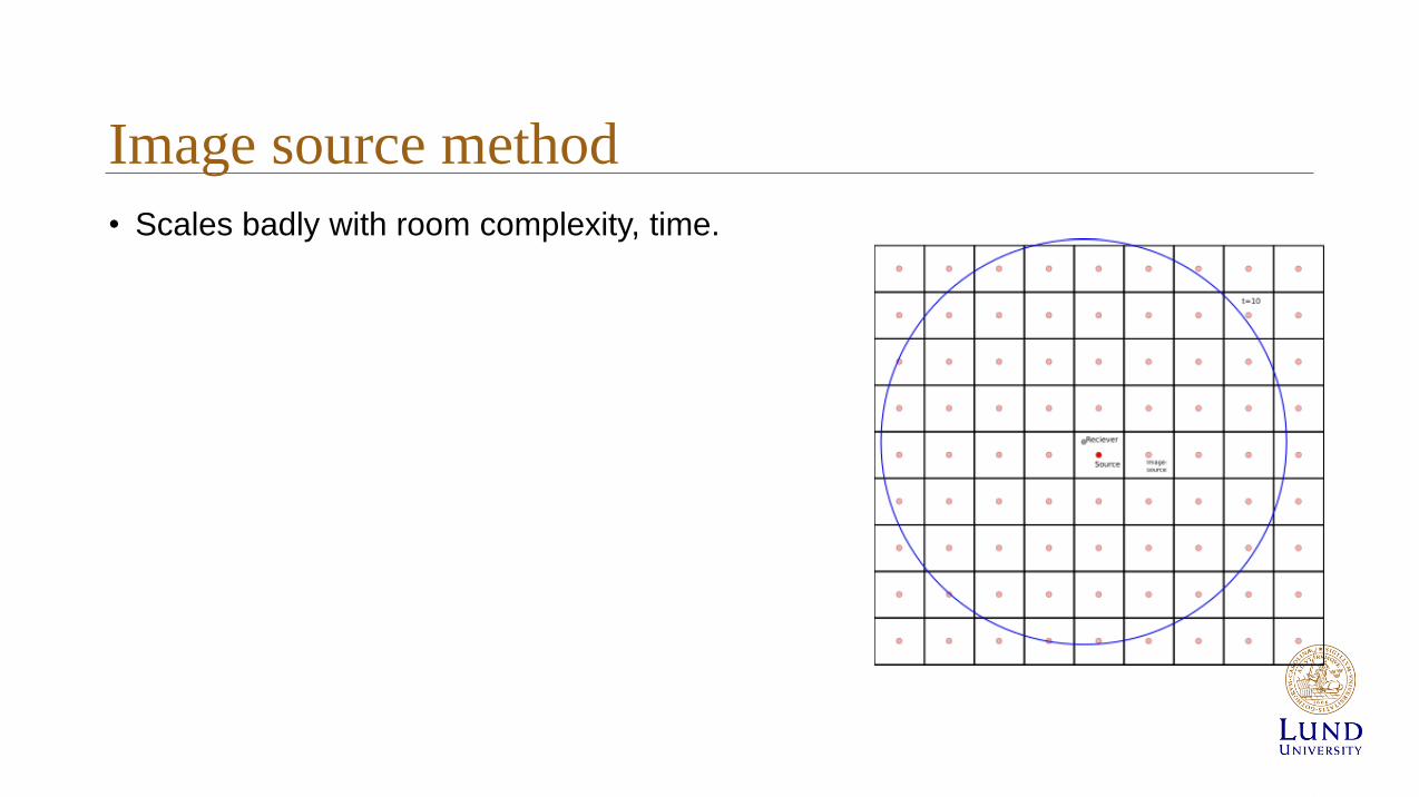
Image source method
• Scales badly with room complexity, time.