modelling and recovery analysis of protection schemes using petri nets
TRANSCRIPT

Electric Power Systems Research, 24 (1992) 199-205 199
Modelling and recovery analysis of protection schemes using Petri nets
Lawrence Jenkins and H. P. Khincha Department of Electrical Engineering, Indian Institute of Science, Bangalore 560012 (India)
(Received March 3, 1992)
Abstrac t
Any systematic study of the effectiveness of the protection scheme of a power system in recovering from a fault requires the development of a suitable model of the protection scheme. In this paper, the relevance of Petri net models to recoverabil i ty analysis is investigated.
I n t r o d u c t i o n
A power system is a dynamic system whose behaviour is described th rough a set of nonlin- ear differential equations. We view its protec- t ion scheme as a discrete event system, since the occurrence of a fault, its detect ion by re- lays, the issue of trip signals, the opening of breakers, the clearing of the fault, and the re- closure of the breakers form a sequence of dis- crete events which occur at specific ins tants of time. The modell ing and performance evalua- t ion of the protect ion scheme must take into account its discrete event behaviour [1-3]. Petr i net models, which have been used exten- sively for the s imulat ion of discrete event sys- tems [4], are an appropriate tool for the s tudy of protect ion schemes. In this context, the pro- tect ion scheme is visualized as a set of binary devices which change state as a consequence of the changes tha t take place within the power system, such as the rise in current level beyond a limit, or the drop in the frequency below a threshold; the dynamics of the power system need not be modelled explicitly, and this decou- pling of the dynamics from the protect ion oper- a t ion aids us in the systematic s tudy of the protect ion scheme. Different Petri net models, such as time Petri nets [5] and stochast ic Petri nets [6], are of relevance to the evaluat ion of different types of studies of the behaviour of protect ion schemes.
Petri net c o n c e p t s
Although formal definitions of Petri nets (PNs) are available [7], we find it convenient to visual- ize a PN as a directed bipart i te graph. Each PN graph consists of two disjoint sets of nodes and two disjoint sets of edges. The n members of the set of place nodes P = {pl, p 2 , . . . , p ,} are repre- sented by circles, and the m members of the set of t rans i t ion nodes T = {tl, t2 . . . . . tin} are repre- sented by bars, as shown in Fig. 1, where m = 3 and n = 4. The directed edges of the set IN are incident out of place nodes and into t rans i t ion nodes, and the directed edges of the set OUT are incident out of t rans i t ion nodes and into place nodes; individual members of these sets are de- noted as IN(pi, tj) and OUT(pi, tj), respectively, where pi and tj are the identifiers of the nodes at which they are incident. Labels are associated with each edge; in the absence of an explicit label, a default value of 1 is assigned. In the case
t l t3
Fig. 1. Example of a Petri net.
0378-7796/92/$5.00 ~'} 1992 - - Elsevier Sequoia. All rights reserved

200
of the Petr i net models of pro tec t ion schemes, each label is 1, so no labels are shown explicitly.
For any t rans i t ion ti, the set of place nodes p, for which the edges IN(p, , t,) are members of IN are known as the input places of t/, while the set of place nodes p~ for which OUT(p~, tj) are mem- bers of OUT are known as the set of ou tpu t places of tj. For instance, in Fig. 1, the set of input places of t rans i t ion t~ is ~p:~, p~ ~,, while the set of ou tpu t places is ~p~,p~. In general, it is permissible for the same place node p, to be both an input place and an ou tpu t place of the same t rans i t ion t:.
Each place node of the PN corresponds to a condi t ion of the system which is modelled by the PN; the presence of a token at this node, which is represented by a dot, implies tha t the condi t ion is cur ren t ly satisfied by the system, while its absence indicates tha t the condit ion is not sa- tisfied. For instance, in the model of a protect ion scheme, one of the place nodes may represent the presence of a faul t in the power system; when a token is present at the place, it corresponds to the presence of the fault, and when there is no token, the fault is absent.
The t rans i t ions correspond to discrete events tha t change the condi t ions of the system tha t is being modelled. The input places of a t rans i t ion correspond to the condi t ions tha t must be sa- tisfied by the system before the event can occur, and the ou tpu t places correspond to the condi- t ions that will be produced by the occur rence of the event. A t rans i t ion is enabled if all its input places have tokens; this implies that all condi- t ions tha t are prerequis i tes for the occur rence of the event are satisfied. An enabled t rans i t ion may fire by removing the token from each of its input places and deposi t ing one at each of its ou tpu t places. The firing corresponds to the occur rence of the event, and the deposi t ion of tokens at its ou tpu t places represents the pres- ence in the modelled system of the condi t ions tha t are a resul t of the occur rence of the event.
The d is t r ibut ion of tokens in the places of the PN model is known as its marking, and repre- sents the state of the system. This information takes the form of an n-vector, whose i th element is equal to the number of tokens at the place p,. For instance, the marking of the PN of Fig. 2 is (1, 1, 0, 1, 0, 0) 'r. The firing of an enabled transi- t ion redis t r ibutes the tokens, thereby changing the marking of the PN. For example, the marking of the PN in Fig. 2 is such tha t the t rans i t ion t~ is enabled, and its firing removes the token from p~ and deposits one in p:~, thereby producing the
pl
i: t2
p5
Fig. 2. Simple Petri net model.
marking (0, 1, 1, 1, 0, 0) 'r. With this marking, both the t ransi t ions t~ and t:~ are enabled, and ei ther may fire. If t: fires, the marking is (0, 0, 0, 1, 1, 0) 'r, and t:~ is no longer enabled, while if t:~ fires, the marking (0, 1, 0, 0, 0, 1) 'r is produced, and t~ is no longer enabled. The firing of t~ enables the transi- t ion t~, whose firing re turns the PN to its initial marking. Similarly, the firing of t:~ enables t;. whose firing produces the initial marking.
Each sequence of t ransi t ions of the PN corre- sponds to a sequence of events tha t can take place in the system that is being modelled, and the corresponding sequence of markings corre- sponds to the sequence of s tates tha t are pro- duced by the occurrence of this sequence of events. In this way, the PN model facil i tates the s imulat ion of a discrete event system.
A useful concept is tha t of reachabi l i ty . For each marking M0 of the PN, the reachabi l i ty set is defined to be the set of all markings that can be obta ined from Mu through the firing of se- quences of t ransi t ions; tha t is, if there exists a sequence of t rans i t ions by which a marking M1 can be obta ined from Mo, then M1 belongs to the reachabi l i ty set of Mo. For instance, in the PN of Fig. 2, the marking (0, 0, 0, 1, 1,0) T belongs to the teachabi l i ty set of the initial marking (1, 1, 0. 1, 0, 0) T, since it can be obta ined from this mark- ing by the firing of the sequence of t ransi t ions It,, t~l.
The reachabi l i ty information of a PN may be convenient ly represented through its reachabil- ity graph. Each node of this graph corresponds to a valid marking of the PN, and each directed edge is associa ted with a t ransi t ion. An edge is incident out of node Mi and into node Mj if there exists a t rans i t ion t/, whose firing changes the marking of the PN from M: to M: ; this edge bears the label tt,,.
The reachabi l i ty graph of the PN of Fig. 2 is given in Fig. 3. It consists of four nodes and five edges, and contains all the reachabi l i ty infbrma- t ion of the PN. It can be seen that for this PN

0 ~ /(1,1.O,l,O. ) '~NN
" [ (0.,,,, 0.0 )' " ~
",~o, oo,~o T o, oo, ol Ir /
Fig. 3. Reachability graph.
every marking can be reached from every other marking because there exists a directed path from each node of the reachabi l i ty graph to every other node. This implies tha t every s tate of the system being modelled can be reached from every other state.
In order tha t a PN model adequate ly repre- sents a pro tec t ion scheme, it is necessary tha t the model possesses the proper t ies of conserva- t iveness, properness and safeness. These proper- ties are determined from the reachabi l i ty graph of the PN.
A PN is conservat ive if there exist posit ive integers wl, w2 . . . . . wn such that , for each transi- t ion tj, the marking M, which precedes the firing of the t ransi t ion, and the marking, M, which succeeds it, sat isfy the re la t ionship
i 1 i - 1
where M ( p i ) and IQ(pi ) are the number of tokens A
at the place node p, for the markings M and M, respectively. Obviously, the proper ty of conser- vat iveness implies tha t a weighted sum of the tokens in the PN remains constant .
In order to es tabl ish whether the PN of Fig. 2 has the conserva t iveness property, we a t tempt to find weights Wl . . . . , we which satisfy (1). Since the firing of t rans i t ion tl removes a token from p~ and deposits a token in Pa, keeping the rest of the tokens unchanged, we choose wl = wa. Similarly, the firing of t2 removes a token each from P2 and Pa, and deposits a single token in p~, so we have w5 = w2 + Wa. By similarly examining the remain- ing t ransi t ions, we choose wl = w2 = wa = w4 = 1 and ws = we = 2. Using these values, we find that all the markings of the reaehabi l i ty graph of Fig. 3 satisfy the re la t ionship (1), and hence the PN of Fig. 2 has the conservat iveness property.
Since the dis t r ibut ion of tokens in a marking contains informat ion with regard to which eondi- t ions are satisfied by the cur ren t s ta te of the system being modelled, the proper ty of conserva- t iveness implies tha t the quan tum of information remains constant . In order tha t the PN model
201
adequate ly represents the system, the proper ty of conservat iveness is required.
A Petr i net has the proper ty of properness if and only if the init ial marking M0 can be reached from every o ther marking of the reachabi l i ty graph.
An examinat ion of the reachabi l i ty graph of Fig. 3 shows tha t the PN of Fig. 2 has the proper- ness proper ty since there exists a directed path from every other node to the node (1, 1,0, 1, 0, 0) T, which corresponds to the init ial marking.
The significance of properness is tha t there exist sequences of t rans i t ions by whose firing one can re tu rn to the init ial marking of the PN from every other marking which the PN can reach. This corresponds to the capabi l i ty of the modelled system to re turn to its init ial s ta te after it has been t ransferred to some other s ta te th rough the occurrence of a sequence of events. Since, in a power system, the pro tec t ion scheme restores the init ial s ta te subsequent to the occurrence of a fault, any valid PN model of the pro tec t ion scheme should possess the proper ty of properness.
The third proper ty of interest is safeness, which is defined in terms of K-boundedness .
A place Pi of a Petr i net is K-bounded if there exists a posit ive integer K such tha t
M(p,) < g
where M is any marking tha t can be reached from the init ial marking. A place p, is safe if it is 1-bounded.
In the reachabi l i ty graph of Fig. 3, each mark- ing M is such tha t e i ther M(p i ) = 0 or/14(p, ) = 1. Hence, every place of the PN of Fig. 2 is 1- bounded, and therefore safe.
In the PN model of a pro tec t ion scheme, each s tate corresponds to a condit ion, and the presence of a token indicates tha t the condi t ion holds. Hence, it follows tha t the number of tokens at a place should be ei ther 0 or 1, since the presence of two or more tokens does not car ry any physical significance. Therefore, we require tha t the P N model of the pro tec t ion scheme be safe.
Till now, we have considered some of the qual- i ta t ive features of Petr i nets. Most s tudies re- quire quant i ta t ive information, such as the firing time parameters of the transi t ions. This may be expressed determinis t ical ly [5] by specifying min- imum and maximum firing times, or stochasti- cally [6] by associa t ing a probabi l i ty d is t r ibut ion with the firing t ime of each transi t ion. Before going into the details of these aspects of Petr i net modelling, we shall consider a simple Petr i net model of a pro tec t ion scheme.
202
S i m p l e P e t r i n e t m o d e l o f a p r o t e c t i o n s c h e m e
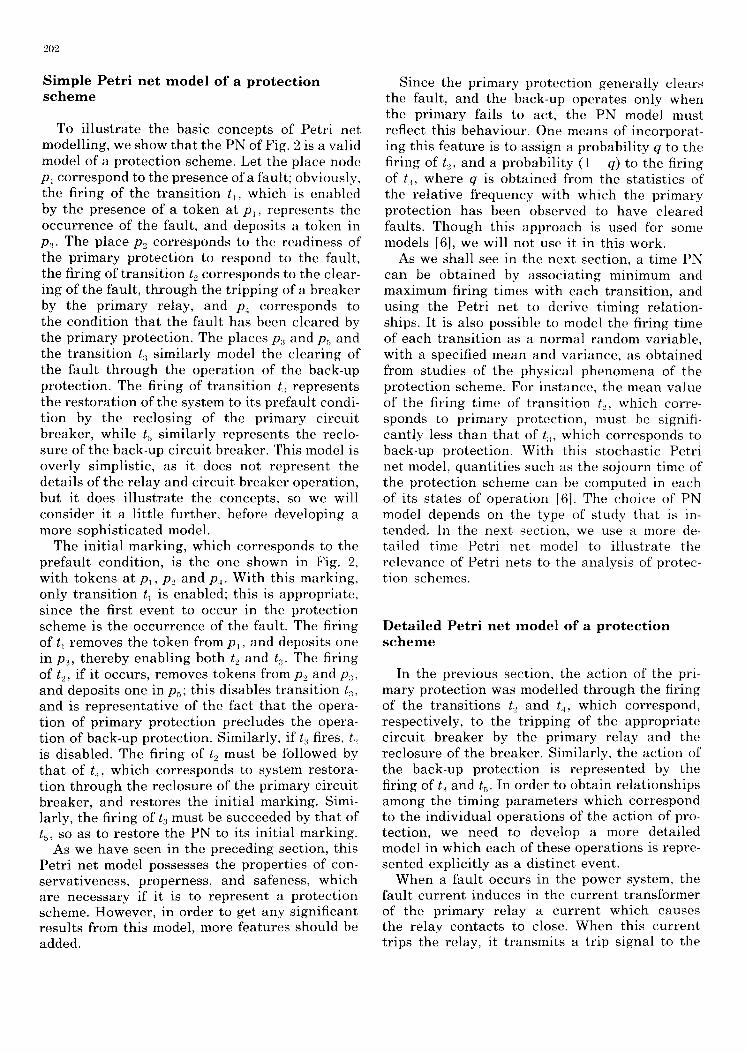
To i l lus t ra te the basic concepts of Petr i net modelling, we show tha t the PN of Fig. 2 is a valid model of a pro tec t ion scheme. Let the place node Pl cor respond to the presence of a fault; obviously, the firing of the t rans i t ion t~, which is enabled by the presence of a token at Pl, represents the occur rence of the fault, and deposits a token in p~. The place P2 corresponds to the readiness of the pr imary pro tec t ion to respond to the fault, the firing of t rans i t ion t2 corresponds to the clear- ing of the fault, th rough the t r ipping of a b reaker by the pr imary relay, and P4 corresponds to the condi t ion tha t the fault has been cleared by the pr imary protect ion. The places p~ and p~ and the t rans i t ion t:~ similarly model the clear ing of the fault th rough the opera t ion of the back-up protect ion. The firing of t rans i t ion t~ represents the res tora t ion of the system to its prefaul t condi- t ion by the reclosing of the pr imary circuit breaker , while t~ similarly represents the reclo- sure of the back-up circui t breaker . This model is over ly simplistic, as it does not represent the details of the re lay and circui t b reaker operat ion, but it does i l lus t ra te the concepts, so we will consider it a little further, before developing a more sophis t ica ted model.
The init ial marking, which corresponds to the prefaul t condit ion, is the one shown in Fig. 2, with tokens at Pl, P2 and p.~. With this marking, only t rans i t ion tl is enabled; this is appropria te , since the first event to occur in the pro tec t ion scheme is the occur rence of the fault. The firing of tl removes the token from p~, and deposits one in p:~, the reby enabl ing both t2 and t:~. The firing of t2, if it occurs, removes tokens from P2 and p:~, and deposi ts one in Ps; this disables t rans i t ion t:~, and is represen ta t ive of the fact tha t the opera- t ion of pr imary pro tec t ion precludes the opera- t ion of back-up protect ion. Similarly, if t~ fires, t2 is disabled. The firing of t2 must be followed by tha t of t,~, which corresponds to system restora- t ion th rough the rec losure of the pr imary circuit breaker , and res tores the init ial marking. Simi- larly, the firing of t3 must be succeeded by that of t~, so as to res tore the PN to its initial marking.
As we have seen in the preceding section, this Petr i net model possesses the proper t ies of con- servat iveness , properness, and safeness, which are necessary if it is to represent a pro tec t ion scheme. However , in order to get any significant resul ts from this model, more features should be added.
Since the pr imary pro tec t ion general ly clears the fault, and the back-up opera tes only when the pr imary fails to act, the PN model must reflect this behaviour . One means of incorporat- ing this fea ture is to assign a probabi l i ty q to the firing of t~, and a probabi l i ty (1 - q) to the firing of t:~, where q is obta ined from the s tat is t ics of the re la t ive f requency with which the pr imary protec t ion has been observed to have cleared faults. Though this approach is used for some models [6], we will not use it in this work.
As we shall see in the next section, a time PN can be obta ined by associa t ing minimum and maximum firing times with each transi t ion, and using the Petr i net to derive t iming relation- ships. It is also possible to model the firing time of each t rans i t ion as a normal random variable, with a specified mean and variance, as obta ined from studies of the physical phenomena of the protec t ion scheme. For instance, the mean value of the firing time of t rans i t ion t~, which corre- sponds to pr imary protect ion, must be signifi- cant ly less than that of t~, which corresponds to back-up protect ion. With this s tochast ic Petr i net model, quant i t ies such as the sojourn time of the protec t ion scheme can be computed in each of its s tates of opera t ion [6]. The choice of PN model depends on the type of s tudy that is in- tended. In the next section, we use a more de- tai led time Petri net model to i l lustrate the re levance of Petri nets to the analysis of protec- tion schemes.
D e t a i l e d Pe tr i n e t m o d e l o f a p r o t e c t i o n s c h e m e
In the previous section, the act ion of the pri- mary pro tec t ion was modelled th rough the firing of the t ransi t ions t2 and t~, which correspond, respectively, to the t r ipping of the appropr ia te circuit b reaker by the pr imary relay and the rec losure of the breaker . Similarly, the act ion of the back-up pro tec t ion is represented by the firing of t~ and ts. In order to obta in re la t ionships among the t iming parameters which correspond to the individual opera t ions of the ac t ion of pro- tection, we need to develop a more detai led model in which each of these operat ions is repre- sented explici t ly as a dist inct event.
When a fault occurs in the power system, the fault cur ren t induces in the cur ren t t ransformer of the pr imary relay a cur ren t which causes the relay contac ts to close. When this cur ren t trips the relay, it t ransmits a trip signal to the

203
tl
p2
t5
Fig. 4. Deta i led Petr i ne t model.
associated circuit breaker, causing its contacts to open. Subsequently, the fault arc is inter- rupted, thereby clearing the fault. The disappear- ance of the fault current deactivates the relay, and its contacts open, thereby resetting it. If the fault is not a permanent one, the reclosure of the circuit breaker restores the system to its prefault condition; otherwise, the presence of the fault causes the relay to operate once again. The be- haviour of the back-up protection is similar to that of the primary, except for the values of the timing parameters; initially, we will model only the primary protection.
The detailed PN model of primary protection is shown in Fig. 4. The events and conditions which correspond to the transitions and places of this Figure are listed in Table 1. While considering this model, we will for the moment ignore the transition and the edges that are shown by bro- ken lines. The prefault conditions are the ab- sence of faults, the circuit breaker contacts being closed, and the relay contacts being open, as represented by the tokens at Pl, P5 and Ps, respec- tively. The firing of transition tl corresponds to
T A B L E 1. Even t s and cond i t ions co r r e spond i ng to t r a n s i t i o n s and p laces of Fig. 1
tl F a u l t occurs t 2 Relay t r ips t 3 C i rcu i t b r eake r opens t4 F a u l t a rc gets i n t e r r u p t e d t o Relay rese t s t o B reake r rec loses
p, F au l t a b s e n t P2 A c t i v a t i n g c u r r e n t p re sen t P3 F au l t c u r r e n t p r e sen t P4 Zero fau l t c u r r e n t P5 B r e a k e r c o n t a c t s closed P6 B r e a k e r c o n t a c t s open P7 Ci rcu i t b r eake r ac t i va t ed Ps Relay c o n t a c t s open P9 Relay c o n t a c t s c losed Plo Relay ac t i va t i ng c u r r e n t
a b s e n t
' '2.
/
/
Fig. 5. Er ror t oken mach ine .
the occurrence of a fault. It is the only transition that is enabled by the initial marking, and its firing removes the token from p, and deposits tokens at P2 and P3, which represent, respec- tively, the presence of an activating current in the relay coil and the presence of fault current. This transition and the resultant marking are shown in the error token machine (ETM) of Fig. 5, from which all the transitions and the resultant markings can be traced. The ETM of a Petri net is obtained from its reachability graph through the inclusion of additional nodes and edges, as will be explained.
The firing of t, enables t2, which corresponds to the tripping of the relay. The firing of t2 removes the tokens from P2 and Ps and deposits tokens in P7 and Pg, which correspond, respectively, to the circuit breaker being activated by a trip signal and the relay contacts being closed. The transi- tion t3 is now enabled; it corresponds to the opening of the circuit breaker. The firing of t3 removes tokens from P5 and P7 and deposits a token in P6, which represents the circuit breaker contacts being open. This enables t4, which cor- responds to the interruption of the fault arc.
The firing of t4 removes tokens from P3 and P6 and deposits tokens at places P4 and Plo, which represent, respectively, zero fault current and the absence of an operating current for the relay. This firing enables both the transitions t5 and t6, and the values of their timing parameters will determine which of them fires first. However, since the sets of input places of these two transi- tions are disjoint, the firing of one of them does not disable the other, and both will definitely fire. We initially assume that t5 fires first.

204
The t rans i t ion ta corresponds to the reset t ing of the relay, which occurs as a consequence of the disappearance of the relay operat ing current . The firing of this t rans i t ion removes a token each from p, and p,~, and deposits one in p.~. The t rans i t ion t~, corresponds to the au tomat ic reclo- sure of the circuit breaker, and its firing restores the Petri net to its init ial marking. This is appro- priate if we consider the PN to represent only protect ion agains t t rans ien t faults which are cleared by the opening of the circuit breaker: we shall see later how permanent faults may also be s imulated th rough this PN model.
Let us now consider what happens if the firing of t~ precedes tha t of t~, after both have been enabled by the firing of t~. The sequence of events can be t raced by considering the edge of the ETM graph with the label t,. which is incident out of the node (p~,p, ,p .)) . In this case, the firing of t~ produces the marking (Pt,P~,P,,P~o), for which both t, and ta are enabled. If t:, fires first, then the PN re turns to its init ial marking, which corresponds to the res tora t ion of the ini- t ial condit ions of the protect ion schemes.
If t~ fires ahead of b,, then the marking (P,~, P:~, Pa,P.~, P~o) is obtained, for which the only enabled t rans i t ion is ts, whose firing produces the mark ing (p~,p:~, p~, Ps). The physical signifi- cance of this firing is tha t ano ther fault occurs before the reset t ing of the relay, which implies tha t the time taken for the issue of the trip signal will no longer be the same, and this will have repercussions in the coordinat ion between the pr imary and the back-up protection. Obviously, it is preferable tha t t~ fires ahead of t,. Let us now examine how this may be achieved. We perform the s tudy by using the time parameters Train i and T, ..... i, which correspond to the mini- mum and maximum time intervals tha t may elapse from the enabling of t rans i t ion t, till it fires.
The firing of t4 s imul taneous ly enables both t~, and t~, th rough the deposit ion of tokens at P4 and P~0, while the firing of t6 enables t~. The minimum time tha t must elapse between the ins tan t of firing of t4 and tha t of t~ is equal to (Tm~.~+ Tmm ~). On the other hand, t5 must fire within Tm,~ ~ time units after the firing of t~. Hence, in order to guaran tee tha t t5 fires ahead of tl, the time parameters must satisfy the re la t ionship
Tm,,~,~ < (T, mn (; + T, mn ,) (2)
While one would not expect a new fault to occur soon after the previous faul t has been cleared, it is possible tha t the original fault was
a permanent one, and in this case the opening ot' the circuit breaker does not remove the fault, which will again be manifest at the ins tant that the circuit breaker is reclosed. Hence T,.., ~--(I. and (2) reduces to
T, ..... r, < Wmi,,i; (;{)
The value of T, ..... :, is obtained from the relay setting, which is chosen on the basis of the desired operat ing time character is t ic of the relay. In or- der tha t (3) be satisfied, the automat ic reclosure mechanism of the circuit breaker must be chosen so as to keep T,,,~,,, sufficiently large. On the other hand, too large a value of the parameter T, ...... ; is also undesirable, since it has an adverse effect on the stabil i ty of the power system.
Recovery through back-up protection
Up to this point, we have considered only pri- mary protection. In order tha t the back-up pro- tect ion come into play, the pr imary protect ion must fail to act. Such failure of the primary protect ion is s imulated by the loss of the token from the place P2 of the Petri net model, after this token has been deposited there th rough the firing of t rans i t ion tl. The loss of the token indicates tha t the pr imary relay is unable to respond to the ac t iva t ing current in the relay coil: it can also represent the absence of the ac t iva t ing current because of the malopera t ion of the sensing device. This loss of the token is shown in the graph of Fig. 5, with the node (P:~,P:,,Ps) repre- sent ing the state tha t is reached from the state (p~, p:~,p~,,ps) th rough the loss of the token at p.~: the edge between these two states bears the label p~. The graph is known as an error token ma- chine, because the new state is obtained by the erroneous behaviour of the system [8].
The state (p:~, p~, Ps) is an illegal state because it is reached th rough an illegal Petri net opera- tion, namely, the loss of a token. If we ignore the edge with the label t~. as shown by broken lines, the state (p:~,p~,p,~) is a final state, since there are no edges tha t are incident out of the node with which it is associated.
By definition, the system can recover from a failure if and only if the ETM which corresponds to this fai lure is such tha t there is only a finite number of illegal states, there are no illegal final states, and there are no loops of directed edges which link only nodes tha t correspond to illegal states. Obviously the node (p:~,p~,,p~) corre- sponds to an illegal final state, and hence the

205
protect ion scheme cannot recover from the fai lure unless it is modified appropriately.
Recovery is faci l i ta ted by ensur ing tha t the illegal state (P3, Ps, Ps) is not a final state. This is achieved by providing the edge tha t is incident out of its node in the ETM of Fig. 5, as shown by the broken lines. This edge bears the label tT, and is incident into the node (P2, P3, P~, Ps). The label t7 indicates tha t the state (P2, P3, Ps, Ps) is reached from (P~,Ps,Ps) by the firing of t ransi t ion tT, which must be provided in the modified Petr i net model of the protect ion scheme. This t ransi t ion is shown by broken lines in Fig. 4; it is enabled by the presence of a token in P3, and its firing deposits tokens in P2 and P3- We will now consider the physical significance of the new transi t ion.
Since the loss of the token at P2 represents the inabil i ty of the pr imary re lay to respond to the fault, its res tora t ion represents the presence of an ac t iva t ing cur ren t in the coil of the back-up relay. This res tora t ion must take place only if a token is present at P3, to represent the presence of a pe rmanen t fault in the power system. Since the ac t iva t ion of the back-up relay by itself does not remove the fault current , which will remain unti l the fault is cleared, as is represented by the firing of t4, the firing of t rans i t ion t7 must restore the token at P3.
The firing of t7 corresponds to the invocat ion of back-up protection, and hence the sequence of t rans i t ion firings tha t follow it will have firing time parameters tha t correspond to the back-up hardware . Apar t from this modification, the s t ruc ture of the PN tha t is used for the simula- t ion of back-up protect ion is the same as tha t used for pr imary protection.
The choice of firing t ime parameters for tv is based on the response time considerat ions of the back-up protection. Since the back-up relay must not respond before the pr imary protect ion has had sufficient t ime to clear the fault, the transi- t ion t7 should not fire unti l it is guaran teed tha t t4 will not fire. Since t7 is enabled by the firing of t,, while t4 is enabled by the successive firing of tl, t2 and t3,
Tmin7 > (Tmax 2 ~- Tmax3 -F- Tmax 4) (4)
where the parameters on the r ight correspond to pr imary protection. From this relationship, a value of Tml, 7 can be selected and used to choose the set t ing of the back-up re lay such tha t it can never respond unless the pr imary protect ion fails.
If the relat ionship (4) is satisfied, the transi- t ion t7 will never fire unless a token is lost from P2, because otherwise t2, t3 and t4 are guaran teed
to fire before Tmin 7 elapses, and the firing of t4 disables tT.
This analysis demonst ra tes the applicabil i ty of Petri net models to the s tudy of t iming relation- ships in protec t ion schemes. With the use of more detai led and complex models, more significant and powerful results may be derived. The study can be extended to protec t ion schemes which consist of a large number of devices.
Conclusion
Petri nets have been shown to be a versat i le tool for the s tudy of protec t ion schemes. The Petri ne t propert ies of conservat iveness, proper- ness and safeness have been considered, and thei r re levance to protec t ion scheme models has been established. Time Petr i nets have been used as a means of obtaining a re lat ionship be tween the time parameters of the protect ion scheme. An error token machine has been used to analyse faulty behaviour, and to provide assis tance to the achievement of recoverabil i ty.
Acknowledgement
The authors wish to acknowledge the contribu- t ion of S. Sh ivakumar to the initial feasibili ty s tudy on the applicat ion of Petri nets to the evaluat ion of protect ion schemes.
References
1 J. A. Juves, R. W. Johnson, E. J. Mayer and S. S. Waters, The concept of figure of merit applied to protection system coor- dination, IEEE Trans., PWRD-1 (1986) 31 40.
2 M. Monseu, Evaluat ion of characteris t ics and performance of power system protection relays and protection systems, Proc. CIGRE Working Group 34, 1980, CIGRE, Paris.
3 M. J. Damborg and S. S. Venkata, Specification of computer aided design of transmission protection systems, EPRI Rep., Electr. Power Res. Inst., Palo Alto, CA, Jan. 1984.
4 P. Corsini and G. Forsini, Methodology for complex system description via extended Petri nets, Comput. Syst. Sci. Eng., 1 (1986) 205 212.
5 S. Shivakumar, H. P. Khincha and L. Jenkins, Modelling and performance evaluat ion of protection systems using Petri nets, EE Rep. No. 73, Dep. Electr. Eng., Indian Inst. Sci., Sept. 1987.
6 L. Jenkins and H. P. Khincha, Deterministic and stochastic Petri net models of protection schemes, IEEE Trans., PWRD-7 (1992) 84 90.
7 J. L. Peterson, Petri Net Theory and Modeling of Systems, Prentice-Hall, Englewood Cliffs, NJ, 1981.
8 P. M. Merlin and D. J. Farber, Recoverability of communica- t ion protocols-- impl icat ions of a theoretical study, IEEE Trans., COM-24 (1976) 1036-1043.