modelling and off-design performance optimisation of a
TRANSCRIPT

Contents lists available at ScienceDirect
Applied Thermal Engineering
journal homepage: www.elsevier.com/locate/apthermeng
Modelling and off-design performance optimisation of a trilateral flash cyclesystem using two-phase twin-screw expanders with variable built-in volumeratioGiuseppe Bianchia,⁎, Matteo Marchionnia, Jeremy Millerb, Savvas A. Tassouaa Brunel University London, Institute of Energy Futures, Centre for Sustainable Energy Use in Food Chains, Uxbridge UB8 3PH, United Kingdomb Spirax Sarco Engineering PLC, Cheltenham GL51 9NQ, United Kingdom
H I G H L I G H T S
• Sliding valve in the expander casingused to vary the built-in volume ratio(BIVR)
• Lower BIVRs improve volumetric effi-ciency but worsen specific indicatedpower.
• Expander BIVR and revolution speedaffect most the heat to power conver-sion.
• Control variables optimised to boostnominal performance from 81 kW to103 kW.
G R A P H I C A L A B S T R A C T
(a)
(b)
min ref maxCase
40
60
80
100
120
Net
pow
er o
utpu
t [kW
]
0.24
0.28
qual
ity
PMP RPM EXP RPM HS MASSPMP RPM EXP RPM HS MASS HS TIN CV OPEN EXP BIVR
cell volume1
2
3
4
5pr
essu
re [b
ara]
BIVR 5.06BIVR 4.29BIVR 3.16BIVR 2.63
two-phase expander TFC system
A R T I C L E I N F O
Keywords:Trilateral flash cycleTwin-screw expanderTwo-phase expanderLow-grade waste heat recoveryBuilt-in volume ratio
A B S T R A C T
This research work presents a numerical chamber model of a two-phase twin-screw expander and its furtherintegration in a one-dimensional model of a Trilateral Flash Cycle (TFC) system for low-grade heat to powerconversion applications. The novel feature of the expander is the capability of changing the built-in volume ratio(BIVR) of the machine through a sliding valve in the casing that opens an additional suction port. Lowering theBIVR from 5.06 to 2.63 results in an improvement of the volumetric efficiency from 53% to 77% but also in areduction of the specific indicated power from 4.77 kJ/kg to 3.56 kJ/kg. Parametric analysis on several degreesof freedom of the full TFC system concluded that expander speed and BIVR are the variables that mostly impactthe net power output of the unit. An optimisation study enabled the net power output of the TFC system, atdesign point, to increase from 81 kW to 103 kW.
1. Introduction
Low-grade waste heat to power conversion has recently attractedincreased attention by the academic and industrial communities. Thepotential for thermal energy recovery and conversion to electricity from
waste heat sources at temperatures below 100 °C has been estimated at468 TWh on a European scale [1] and 43.2 PWh worldwide [2]. Ac-cording to the aforementioned studies, the most promising sectors forharvesting this potential are the chemical and petrochemical, the non-metallic minerals as well as the food and tobacco industries.
https://doi.org/10.1016/j.applthermaleng.2020.115671Received 12 November 2019; Received in revised form 22 May 2020; Accepted 28 June 2020
⁎ Corresponding author.E-mail address: [email protected] (G. Bianchi).
Applied Thermal Engineering 179 (2020) 115671
Available online 03 July 20201359-4311/ © 2020 The Author(s). Published by Elsevier Ltd. This is an open access article under the CC BY license (http://creativecommons.org/licenses/BY/4.0/).
T

Among the available technologies, heat to power conversion sys-tems are characterised by higher flexibility than heat exchanger net-works for recovery and internal reuse of the energy and for over thefence export. Bottoming thermodynamic cycles, and particularlyOrganic Rankine Cycles (ORC), are a mature technology for waste heatto power conversion especially at medium heat source temperaturelevels in the range 150–300 °C and at power sizes in the order ofmegawatts [3]. For low-grade heat recovery applications, the academicliterature proposes the trilateral flash cycle as a promising candidate forheat to power conversion [4].
The TFC differs from the ORC in the absence of phase change duringthe heat addition and expansion in the two-phase region of the organicworking fluid. In [5], a TFC using water and four ORC configurationswere compared considering an expander isentropic efficiency of 85%.The findings revealed 14–29% higher values of exergetic efficiency inthe case of TFC depending on the inlet temperatures of heat source andsink. Moreover, the volume flow rate at the expander outlet was sig-nificantly higher in the TFC system, from 2.8 to 70.0 times greater thanthe ORC in the same operating conditions. Therefore, it was suggestedthe utilization of fluids with higher vapour pressures such as cyclo-pentane and butane. In a later study, based on the same conditionsdescribed in [5], a comparison was carried out between TFC operatingwith organic fluids and water, an ORC and a Clausius-Rankine cycle.The TFC with water outperformed all the other cycles in terms of ex-ergetic efficiency [6].
Two-phase expansion technologies are commercially available forsome niche applications. In the context of mechanical power generationfrom geothermal fluids, impulse steam turbines are the state of art atmegawatt scale [7]. In addition to that, a 1 kW two-phase reactionturbine, whose concept was patented by Fabris [8], has been recentlyanalysed and optimised through multi-phase Computational Fluid Dy-namics (CFD) using the Thermal Phase-Change model [9]. In LiquefiedNatural Gas (LNG) applications, a commercial radial turbine [10] re-sulted in an empirical isentropic efficiency up to 85% [11] with a powersize in the order of tens megawatts.
To seize the opportunity provided by distributed low-grade wasteheat sources, an ideal electrical power size for TFC systems rangesaround 100 kW. In fact, this allows transportability of the power re-covery units, use of off-the-shelf equipment, low footprint and in-stallation complexity, and a still adequate business case [12]. At thisscale, positive displacement machines are more preferable than thedynamic ones given the high-pressure ratios and the relatively smallmass flow rates. Nonetheless, research is also ongoing to develop TFCimpulse turbines. In particular, an experimental study on the con-verging–diverging nozzle of a TFC impulse turbine showed a pro-gressive increase in the nozzle efficiency by a rise in the inlet
temperature of iso-pentane up to 45% at 68.3 °C [13]. On the otherhand, an Euler impulse turbine operating with R245fa resulted in anexperimental power recovery up to 7 kW. The study further highlighteda number of advantages of TFC compared to ORC, such as up to 80%additional power output at the same operation conditions as well assimplified control of the heat to power block [14].
Unlike those positive displacement technologies that experience alimitation in the revolution speed to minimise the friction losses oc-curring between stationary and moving parts, twin-screw expanderscan operate at high speeds, up to 6000 RPM. This feature results in thecapability of processing large quantities of flow and reduced investmentcosts. As such, even though some studies on reciprocating TFC ex-panders are also available [15], most of the published literature focuseson the twin-screw technology.
Twin-screw machines have been thoroughly investigated throughnumerical and experimental approaches when used as air or refrigera-tion compressors and as ORC expanders [16]. Among them, somecommercial solutions for two-phase ORC expanders have been alsodeveloped [17,18], while a recent analysis concluded that for heatsource temperatures ranging between 80 °C and 200 °C, the optimalcritical temperature of the working fluids ranges between 125 °C and175 °C, (e.g. R245ca, iso-pentane and n-butane) [19]. Nonetheless, tothe best of the authors' knowledge, the availability of literature on two-phase twin-screw expanders for TFC applications is not sufficientlythorough to provide a deep understanding of the underpinning physicsof the flash expansion in these machines.
The first research outputs on twin-screw expanders for TFC appli-cations are from the research group at City University London. In [20],a 10 year study on TFC and twin-screw expanders is presented. Ex-tensive numerical and experimental activities were carried out with thethen available working fluids. Results reported an output power in theorder of 25 kW and isentropic efficiency close to 70%. The authors alsohighlighted the issue of pre-expansion during the initial filling workingchambers. The chamber model developed, assuming homogeneous two-phase flow, also showed a good agreement with the experimental re-sults. In [21], the geometrical optimization of a twin-screw machine forthe expansion of wet steam is presented. With reference to a modelwhich calculated the two-phase fluid properties as the average of thesingle phase ones weighted on the quality, the numerical work pro-posed a multi-variable geometric optimization to maximise the outputpower. The optimized geometry was tested at different expansion ratiosand achieved isentropic efficiency greater than 70% at nominal con-ditions.
In [22], a thermodynamic modelling for TFC twin-screw expandersis presented. The modelling approach considers the filling process as ifthe working chambers are filled with a hot liquid over an injector
Nomenclature
e specific total internal energy [J kg−1]cp specific heat at constant pressure [J kg−1 K−1]h specific enthalpy [J kg−1]m mass [kg]m mass flow rate [kg s−1]p pressure [Pa]r specific internal energy [J kg−1]t time [s]u velocity [m/s]x qualityA area [m2]B total number of boundariesH heat transfer coefficient [W m−2 K−1]Pind indicated power [W]R equivalent gas constant [J kg−1 K−1]
T temperature [K]V volume [m3]Z number of rotor lobes
ratio of specific heatsefficiencydensity [kg m−3]
θ valve liftφ control valve area ratio
revolution speed [RPM]01 total upstream conditions2 static downstream conditionsis isentropichot heat sourceleak leakages heat transfer surfacesuc suctionvol volumetric
G. Bianchi, et al. Applied Thermal Engineering 179 (2020) 115671
2

nozzle rather than an inlet area to improve flash vaporization of thefluid. The leakage calculation is instead handled with a homogeneousmixture approach. As concerns the energy equation, a thermodynamicequilibrium is considered. This assumes that sufficient heat transferexists between the phases to reach a stable state within a time step. Thesimulations showed good agreement with measurements performed ona steam expander, even though deviations on the power output andindicator diagram were noticed especially at low revolution speeds.
In [23], extensive experimental investigations are carried out on awater injected twin-screw expander, including indicating pressuremeasurements. The experiments showed a better volumetric efficiencyat lower revolution speeds and an almost constant mechanical effi-ciency when the quality ranged between 0.97 and 0.99. This resultagrees with the simulations performed in [24] in which it is concludedthat at high steam qualities, the specific flow consumption (i.e. ratiobetween power recovered and steam used) is optimal.
In [25], the impact of different rotor-tip clearance heights was in-vestigated concluding that greater rotor-tip gaps, albeit providing agreater mechanical efficiency, result in lower power recovery perfor-mance due to worse indicated and isentropic efficiency.
In [26], a correlation between isentropic efficiency and inlet qualityis proposed based on data from previous experimental works on two-phase twin-screw expanders, [20,27,28]. The correlation indicates thatdifferences in adiabatic efficiency tend to level out with reducing va-pour fraction. Designs with poor peak efficiency tend to improve at lowvapour fraction conditions while designs with high peak efficiencybecome less efficient at lower vapour fractions.
The effects of surface condensation in steam-driven twin-screw ex-panders were recently assessed through a chamber model simulationcoupled with a thermal analysis for the heat transfer between fluid andmetallic surfaces. The study concluded that, due to the short time scalesand the periodicity of the expansion, the condensation process is bestdescribed by models for dropwise condensation. Moreover, the researchasserted that condensate is trapped in the working chamber at the endof the filling period, thus increasing the mass flow rate of the machinebut with no effects on the power output [29].
All the research works agree on the complexity of the phenomenainvolved in a flashing expansion in screw machines. Hence, some re-searchers began to investigate the fundamentals in more simplifiedmachines, namely piston geometries [30]. A two-phase piston expanderwas also experimentally and numerically investigated in [31]. From theexperimental investigations, it was identified that the mixing of theliquid due to boiling bubbles was found to have a strong impact onpressure change during adiabatic expansion. Hence, two-phase adia-batic vaporization in a cylinder is considered to be mainly dominatedby the heat transfer between the bulk liquid and the gas–liquid inter-face. These operating conditions, however, are not fully representativeof the reality in twin-screw machines since the phase change processtakes place while the fluid in the control volume rotates and simulta-neously mixes with other flows.
In this context, the current research proposes to address theknowledge gap related to the expander operation as well as the inter-action effects between the different components of a TFC system interms of sensitivity and impact on recovery performance also at off-design conditions. The novelty of the research methodology employedin this work lies in the scalability of the results for optimization andcontrol studies. Another element of novelty compared to the state of theart is the numerical investigation of the effects that a variation of theexpander built-in volume ratio has on the machine performance and theoverall power recovery. This work also expands recently publishedwork on Trilateral Rankine Cycles and partial-evaporating cycles, suchas [32,33] and [34] respectively.
In Section 2, after introducing modelling methodology, the conceptof variable built-in volume ratio (BIVR) presented. Section 3 insteadfocusses on the novel modelling features of the TFC heat to power unitpresented in [12]. In Section 4, a first set of simulations on the
standalone twin-screw machine is followed by the off-design perfor-mance assessment of the TFC unit. Maps reporting the optimal oper-ating conditions for given temperatures and flow rates of the heatsource are eventually presented and discussed.
2. Twin-screw expander modelling
2.1. Fundamentals
The twin-screw expander and the other components of the TFCsystem have been modelled in the commercial software platform GT-SUITETM [35]. In this environment, positive displacement machines aremodelled through lumped parameter formulations, also known aschamber models [36]. As concerns piping and heat exchangers, a one-dimensional formulation of the conservation equations solved with astaggered grid approach is instead considered. Dynamic machines suchas the centrifugal pump of the TFC system are eventually modelledusing a map-based approach [37].
The expander performance maps discussed in Section 3.1 weregenerated through the standalone expander model presented in [36]and adapted to include the variable built-in volume ratio capability.The cornerstone of this modelling approach, which applies to any po-sitive displacement machine, is the energy equation expressed in termsof conservation of total internal energy, i.e. the sum of internal energyand kinetic energy ( = +e r u 22 ). The energy Equation (1) states that,neglecting variations of potential energy, the rate of change of totalinternal energy in the expander chambers depends on their volumevariation, the enthalpy fluxes through the boundaries (leakages, suctionand discharge ports) and the heat transfer phenomena with casing andthe rotors (neglected in the current case).
= + +=
d medt
pdVdt
m ep
HA T T( ) ( )i
B
i ii
is fluid wall
1 (1)
This lumped parameter formulation assumes no spatial variation ofthe fluid properties inside the expander chamber. The two-phase fluidsare treated as equivalent gases whose thermophysical properties arecalculated as the weighted average of the saturated liquid and vapourstates based on quality. Eq. (2) reports an example for the ratio ofspecific heats.
= +x x(1 )vap liq (2)
Leakage flows as well as filling and emptying processes are treatedas flow through an orifice whose equivalent diameter is an input of thecalculation. In the case of subsonic flows, Eq. (3) applies.
=m App
RTpp
21
1leak leak 012
01
1
012
01
1 21
(3)
In absence of friction losses, the expander power output equals tothe indicated power Eq. (4).
=P Z pdV60ind male (4)
The volumetric efficiency is defined as the ratio between the massflow rate resulting from the simulation and the theoretical value thatcan be calculated from the geometrical and operational characteristicsof the machine according to Eq. (5).
= mV Z
60vol
suc suc male (5)
The isentropic efficiency is eventually calculated as the ratio of thereal and the isentropic enthalpy drops across the expander, i.e. withinlet and outlet enthalpies measured at mid-length of the intake andexhaust ducts respectively, Eq. (6).
G. Bianchi, et al. Applied Thermal Engineering 179 (2020) 115671
3

= h hh his
is
01 2
01 2, (6)
2.2. Variable built-in volume ratio
In positive displacement expanders, the fluid intake occurs througha narrow port which is designed to guide the high-pressure compres-sible flow through the expander cells. In TFC applications, this port hasto provide suitable opening for a flow whose density can easily fluc-tuate if the system is not operating at design or steady state conditions(startup, transients, shutdown). From test experience, it has beenidentified that a large amount of liquid flowing through the suction portcreates severe instability in the expander operation and significantnoise and vibrations. The purpose of the sliding valve is therefore tomitigate these phenomena as well as change the built-in volume ratio(BIVR) of the machine to cater for different operating conditions.
The variation of the expander BIVR takes place through a slidingvalve, i.e. a regulation screw that drives the linear motion of the bottompart of the casing. This approach essentially creates an additional suc-tion port that, unlike the one on the high-pressure end wall of the ex-pander, is radial and not axial. When the screw is completely tightened,the expander has a conventional layout with only the axial suction port.Otherwise, there is a cubic relationship between number of turns of theregulation screw and expander BIVR. The opening of the radial suctionport requires an accurate modelling of the twin-screw expander geo-metry to be retrieved and, in the current study, it was provided by themanufacturer. The implementation of the sliding valve in the modelledtwin-screw expander is reported in Fig. 1 while Fig. 2 shows the angularevolution of cell volume, discharge port area as well as radial and axialsuction ports areas; the data reported span the available BIVR range(2.63–5.06) in four positions of the regulation screw.
The availability of the geometrical data of Fig. 2, together with theequivalent areas of the leakage paths, is essential for the expandermodelling using the approach proposed in this paper. As such, shouldnot these data be available, one should either liaise with the manu-facturer or rely on geometrical pre-processors for twin-screw machinescommercially available [38] or even measured from Computer-AidedDesign software [39]. Additional information on the expander used astest case in the current work are reported in Table 1 [36].
Boundary conditions for the simulations were pressure and enthalpyat the inlet duct of the expander, pressure and quality at the outlet ductand revolution speed (Table 2). The variable combination used for theinlet boundary conditions allows single and multi-phase simulations.This is particularly relevant when the expander is integrated in the fullTFC system model. Moreover, the quality boundary condition at theoutlet of 0.4 applies only in the case of backflows, which is unlikely tohappen in this application.
3. TFC system modelling
To assess the effect of the variable expander geometry on the systemperformance, a holistic model of a TFC-based heat to power conversionsystem has been also developed in GT-SUITETM. The model block dia-gram is shown in Fig. 3.
In the application here considered, the heat source and sink are bothwater streams while the working fluid is R245fa, whose thermophysicalproperties are retrieved through an interface with the NIST Refpropdatabase [40]. Although it is being phased out, the reason for choosingthis working fluid is to align the simulations with the ongoing experi-ments. Furthermore, in the TFC prototype being tested, a small quantityof POE oil was diluted in the R245fa since the expander bearings arelubricated through the working fluid. However, in the current study,the TFC was assumed to operate with pure working fluid since the ac-tual quantity of oil through the expander and not accumulated in theheat exchangers is hardly quantifiable.
A control valve is eventually considered upstream of the expandersto regulate the fluid inlet conditions. In particular, if on one handthrottling the flow leads to a pressure loss, on the other one the higherquality of the working fluid may ensure a better expander operation.The novel modelling features developed in the current study deal withthe expanders performance maps and the control valve.
3.1. Multi-dimensional expander performance maps
The performance maps of the expander are calculated using themodel presented in the Section 2. In particular, the expander perfor-mance depends on the inlet quality of the working fluid, the mano-metric expansion ratio, the revolution speed and the BIVR [36]. Thus,all these parameters have been considered to predict the behaviour ofthe machine in the full TFC system model. To do that, the conventionaltemplates available in the software cannot be used. Therefore, multi-dimensional look-up tables have been implemented. In these tables, theexpander revolution speed, pressure ratio, inlet quality and the BIVRconstitute the independent variables, while the mass flow rate and theisentropic efficiency of the machine are the dependent ones.
Each multi-dimensional map requires the combination of severaltwo-dimensional maps having revolution speed and pressure ratio asindependent variables. For instance, assuming three levels of variationfor the inlet quality and three for the BIVR, the multi-dimensional mapwould require nine two-dimensional maps across which interpolationsare performed.
The operating ranges of the independent variables were selectedbased on geometrical (BIVR) or functional characteristics or the ma-chine (revolution speed) [36] as well as considerations resulting fromthe cycle analysis (cycle pressure ratio, fluid quality at the expanderinlet) [12]. More specifically, the revolution speed was varied between1500 RPM and 6000 RPM, the expansion ratio from 1.5 to 8.5, therefrigerant quality between 0.0 and 0.6, and the BIVR from 2.63 to
Fig. 1. Sliding valve implementation in the modelled twin-screw expander: (a)picture of the expander with the valve fully tightened, (b) 3D view of themachine having the sliding valve fully open (courtesy of Howden CompressorsLtd.)
G. Bianchi, et al. Applied Thermal Engineering 179 (2020) 115671
4

5.06.The multi-dimensional look up is carried out as follows: (1) the
expander pressure ratio is calculated from the high and low cyclepressures which output from the heat exchangers sub-models; (2) thefluid quality at the expander inlet results from the energy balance at theheater; (3) the expander BIVR and revolution speed are given asboundary conditions; (4) mass flow rate and isentropic efficiency resultfrom the multi-dimensional interpolation while, beyond the range ofindependent variables considered, a linear extrapolation method isemployed.
3.2. Control valve and other sub-models
The globe control valve has been modelled as an orifice with avariable diameter. For a given lift θ, i.e. position of the stem, the valve
area ratio φ is defined as the current flow passage area divided by themaximum one. The relationship between the two parameters is re-ported in Eq. (7).
==
=AA
( ) ( )( 1)
1.151 0.151
When the valve is fully open (θ = 1), the flow passage area is equal tothe cross section of the adjacent pipes, whose inner diameter is130 mm. To prevent any blockage of the flow, the minimum valueconsidered for φ during the analysis is 9%. This corresponds to anequivalent diameter of the flow passage area of 39 mm and a lift θ equalto 0.63%.
The plate heat exchangers (heaters and condensers), the centrifugalpump, the receiver and the piping have been modelled using a set ofdedicated templates available in the software platform and thoroughlypresented in [37].
3.3. Simulation setup
The boundary conditions imposed for the system model are: thepump and expander revolution speed, the expander BIVR, the controlvalve area ratio, and the inlet temperatures, mass flow rates and pres-sures of hot and cold sources (all indicated in lowercase letters inFig. 3). The numerical problem is solved with an implicit method thatapproximates the set of algebraic differential equations to a set ofnonlinear algebraic ones [35].
The simulation outputs are thermal quantities since no mechanicaland electrical losses have been taken into account. More specifically:the expanders power output is the twice the indicated power of eachexpander; the net power output is the difference between expandersand pump powers; the cycle thermal efficiency is the ratio between thenet power output and the thermal power recovered at the heater (Eq.(7)).
=P P
m c T T2
( )TFCind pump
hot p hot hot in hot out, , , (7)
4. Results and discussion
4.1. Twin-screw expander simulations
Prior to integration of the expander model in the TFC system one,some expander-focussed simulations are presented. With reference tothe boundary conditions reported in Table 2, Fig. 4 provides a com-parison of the pressure and quality indicator diagrams for the BIVRsresulting from the configurations reported in Fig. 2. Fig. 5 insteadsummarizes the key performance parameters such as efficiency andpower. Since the modelling approach herein considered does not takeinto account friction losses, the power reported in Fig. 5 is the indicatedone, not the one at the shaft; consequently, no mechanical efficiencycould be estimated.
Even if the inlet pressure was set to 5 bar, Fig. 4 shows that, re-gardless of the BIVR, the actual value during the suction process is al-ways lower; this is due to the pre-expansion in the suction manifold thatfeeds the expander cells [36] as well as the throttling loss through thesuction port, whose opening is reported in Fig. 2. Moreover, this phe-nomenon increases with the revolution speed. In the case of lowerBIVRs, a reduction of pre-expansion is observed: for a BIVR of 5.06 thesuction pressure is 4 bar, while when the BIVR is equal to 3.16 theexpander cells are filled at 4.4 bar. This is consistent with findings in[22]. Beyond a BIVR of 3.16, the benefit on the pre-expansion reductionis marginal, even if the duration of the suction process is longer as onewould expect from the extended positioning of the radial suction port.This phenomenon can be explained with the support of Fig. 5, whichshows an increase of mass flow rate at lower BIVR for the same pressure
Fig. 2. Angular evolution of expander cell volume and ports areas in four po-sitions of the sliding valve (courtesy of Howden Compressors Ltd.)
Table 1Main geometrical and operating features of the modelled expander.
Rotor diameter 204 mm
Aspect ratio(L/D) 1.65Built-in volume ratio 2.63–5.06Male/female rotor lobes 4/6Suction/discharge ports arrangement axial/axialRevolution speed range 1500–6000 RPMTip speed range 16–64 m/sWeight 887 kg
Table 2Simulation setup for Figs. 4 and 5.
Working fluid R245fa
Revolution speed 3750 RPMInlet pressure 5.0 barOutlet pressure 1.3 barOutlet quality 0.4Inlet enthalpy (quality = 0.1) 301 kJ/kg
G. Bianchi, et al. Applied Thermal Engineering 179 (2020) 115671
5

boundary conditions of the simulations. Therefore, the larger openingdue to the radial suction port allows to intake a larger amount of fluidwhich consequently leads the volumetric efficiency of the machine toincrease. Hence, the pre-expansion decreases thanks to the increasedvolumetric performance. In a fixed BIVR expander operating at steadystate conditions, the same benefits could be achieved through a suitabledesign of the intake manifold.
For the same manometric pressure ratio, lower BIVRs lead to under-expansion phenomena that can be clearly seen from Fig. 4. Moreover,one can notice that the cell pressure does not suddenly adapts to thedischarge value. Similar trends have been found experimentally [25],even though the data refer to water as working fluid. This deviationfrom an ideal isochoric process may be due to the finite capacity of thedischarge plenum as well as the gradual opening of the discharge port(Fig. 2). This aspect was also noticeable in simulations performed usingthe same modelling platform but with reference to a single phase ORCsliding vane expander [41]. The under-expansion leads to a decrease ofthe expander isentropic efficiency, as reported in Fig. 5. The total in-dicated power instead increases at lower BIVR due to the larger massflow rates involved. However, due to the lower isentropic efficiency, atlower BIVRs correspond lower specific indicated powers.
4.2. TFC system simulations
To assess the impact of the main process variables on the TFCsystem and expander performance, a parametric study has been carriedout varying the model boundary conditions with respect to the re-ference point presented in Table 3. For each variable changed, the re-maining ones have been kept constant and equal to their referencevalues. The effects of these variations have been assessed from a systemperspective by evaluating the cycle thermal efficiency and net poweroutput, and from the expander one, by analysing the isentropic effi-ciency and the refrigerant quality at the inlet of the machine. The in-vestigated range of the parameters varied is reported in Table 4.
4.2.1. Control valve openingFig. 6 shows the effects of the flow throttling through the globe
valve with reference to the operating point reported in Table 3. Al-though the results are focussed on the valve, the simulations werecarried out at system level and not considering the globe valve as astandalone component. The analysis is presented in terms of lift andarea ratio, both defined in Section 3.2, and considers the pressure dropacross the valve as well as the percentage variations of the volume andmass flow rates as dependent variables.
When the valve area ratio is decreased from 100% (valve fully open)to 9% (valve lift of 1%), the pressure drop increases from 0.01 bar to3.5 bar. At the same time, the valve throttling results in a volume flowrate reduction from 100% to 15%. Since the refrigerant flashing isshifted from the heater to the control valve, the substantial decrease inthe volumetric flow rate is compensated by an increase of the workingfluid density at the inlet of the control valve. As such, the decrease inmass flow rate is only limited from 100% to 8%.
This phenomenon can be explained as follows: the additionalpressure drop introduced by the closure of the valve undoubtedlymodifies the circuit impedance. This leads the pump to supply a greaterhead and, in turn, a flow at higher pressure. For the same heat input atthe heater, since the latent heat of vaporisation reduces at increasingpressures, the high-pressure refrigerant flow now requires a larger pre-heating compared to the reference case. As a result, at the inlet of thecontrol valve the refrigerant flow has a higher density, because of thehigher pressure, and a lower quality, due to the larger pre-heating.These operating conditions allow to balance the volume flow rate re-duction.
The effects of the flow throttling via the control valve on the TFCsystem performance are presented in Fig. 7. From a theoretical per-spective, throttling a flow upstream of an expander would have a det-rimental impact on the overall power output since an expansion processacross the valve does not perform any work. In the current case, how-ever, the mass flow rate compensation discussed in Fig. 6 and the higherrefrigerant quality at the inlet of the expanders instead lead to a 22%increase of the specific power output. In fact, when the valve area ratio
Fig. 3. TFC system model: lower case labels refer to boundary conditions.
G. Bianchi, et al. Applied Thermal Engineering 179 (2020) 115671
6

goes from 100% to 9%, the refrigerant quality at the inlet of the ex-panders increases from 0.11 to 0.16 (Fig. 7.b). For the same mass flowrate (Fig. 6), this results in an overall higher absolute enthalpy of thetwo-phase refrigerant flow upstream of the expanders which, in turn,generate a power output increase from 110 kW to 123 kW. With respectto the overall heat to power conversion unit, this results in a perfor-mance increase: the net power output and thermal efficiency go from80 kW to 101 kW and from 4.3% to 5.2% respectively (Fig. 7.a).
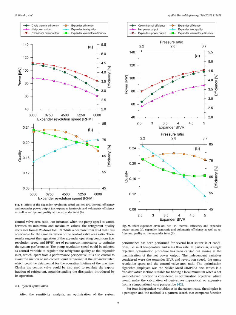
4.2.2. Expander revolution speedFig. 8 shows the results obtained by varying the expander speed and
maintaining constant the pump one. In particular, it is possible to ob-serve that when the revolution speed of the expander increases from3000 RPM to 6000 RPM, the efficiency of the machine decreases fromthe optimal value of 78% to the minimum of 66% (Fig. 8.b), with aconsequent decrease in the power generated, from 110 kW to 90 kW.An increase of revolution speed negatively affects the filling of themachine, with a resulting drop of volumetric efficiency and poweroutput. The reduced power generated by the expanders also leads to adecrease of the system net power output and thermal efficiency, whichgo from 85 kW to 61 kW and from 4.3% to 3.0% respectively (Fig. 8.a),
being the pump power consumption constant (fixed pump revolutionspeed).
For the same expander revolution speed variation, the refrigerantquality at expander inlet increases from 0.15 to 0.20 (Fig. 8.b). Inparticular, higher expander speeds lead to higher volumetric flow ratesprocessed by the machine, while the mass flow rate in the system is
Fig. 4. Indicator pressure (a) and quality (b) diagrams at different BIVRs; si-mulation conditions reported in Table 2.
Fig. 5. Effects of BIVR on the expander performance: results refer to the samesimulation conditions as in Fig. 4 (see Table 2) and are reported in terms ofefficiency (left y-axis), mass flow rate, specific and absolute indicated powers(right y-axis).
Table 3Reference operating conditions.
Cycle variables Hot water R245fa Cold water
Mass flow rate [kg/s] 7.84 24.80 130.30Inlet/Max pres [bar] 4.0 6.4 3.0Outlet/Min pres [bar] 3.9 1.1 2.7Inlet/Min temp [°C] 85 18 12Outlet/Max temp [°C] 25 63 17System performance and setupNet power output [kW] 81Thermal efficiency 4.0%Expander efficiency 74.0%Valve opening 100.0%
Table 4Simulation matrix for the off-design analysis of the system.
Hot source Min Ref Max
Mass flow rate kg/s 5.49 7.84 10.19Inlet temperature °C 75 85 95Inlet pressure bar 4Cold sourceMass flow rate kg/s 130.3Inlet temperature °C 12Inlet pressure bar 3TFC equipmentPump speed RPM 2500 3000 3500Expander speed RPM 3000 4500 6000Expander BIVR 2.63 5.06 5.06Control valve area ratio 9.0% 67.5% 100.0%
G. Bianchi, et al. Applied Thermal Engineering 179 (2020) 115671
7

fixed by the constant revolution speed of the pump. Then, to balancethese two quantities, the pressure at the expander inlet has to decrease,with a resulting increment of the organic fluid quality.
4.2.3. Expander built-in volume ratioAnother variable that allows further controlling of the expander
operating conditions is the position of sliding valve, which affects themachine Built-In Volume Ratio (BIVR). The results of the analysis arepresented in Fig. 9.
When the BIVR is increased from 2.63 (sliding valve fully open) to5.06 (sliding valve fully closed) the pressure ratio across the machinerises from 2.2 to 3.7; as a consequence, the expander power outputincreases from 80 kW to 110 kW. Thus, being the pump power con-sumption and the thermal load at the heater fixed (pump revolutionspeed and inlet hot source conditions constant during this set of si-mulations), the TFC net power output and thermal efficiency also in-crease from 60 kW to 80 kW and from 3.0% to 4.5% respectively(Fig. 9.a). The lower pressure ratio achieved by lowering the expanderBIVR also leads to a refrigerant quality increase at the inlet of themachine, which goes from 0.12 for a BIVR of 5.06 to 0.24 for a value of2.63 (Fig. 9.b).
4.3. Sensitivity analysis
The impact of the operating parameters investigated in paragraph4.2 on the TFC system performance have been compared in Fig. 10together with the effects of pump revolution speed and heat sourcemass flow rate and inlet temperature. As for the methodology pre-viously described, each variable has been individually changed fromthe minimum to the maximum value of their respective range (reportedin Table 4), while keeping constant and equal to the reference valuesthe remaining ones. Compared to the previous analysis, instead ofconsidering the control valve as fully open (100% of the opening area)and the sliding valve fully tightened (BIVR of 5.1), to make a reasonablecomparison, the minimum, reference and maximum values of theaforementioned variables have been set equal to 9%, 67.5%, 100%(control valve area ratio) and 2.5, 3.7, 5.1 (BIVR) respectively.
Fig. 10.a presents the analysis referred to the net power output ofthe TFC unit, while Fig. 10.b relates to the refrigerant quality at theexpander inlet. Apart from the hot source inlet conditions, which are
mainly related to the topping process variability, the net power outputof the TFC system is particularly sensitive to a variation of the BIVR andrevolution speed of the expander. The net TFC power indeed varyiesfrom 57 kW to 83 kW and from 90 kW to 60 kW when the aforementioned parameters span their whole ranges. The other parametersas the control valve area ratio and the pump revolution speed have alower impact (Fig. 10a). Therefore, since the expander revolution speedand the BIVR mainly affect the efficiency of the machine and the cyclepressure ratio, these latter parameters show the most prominent impacton the system performance.
Besides the expander BIVR, the refrigerant quality at the expanderinlet is strongly affected also by the pump revolution speed and the
Fig. 6. Pressure drop across the globe control valve at different openings andeffects on the flow rate with respect to the conditions listed in Table 3.
Fig. 7. Effect of the control valve area ratio on: net TFC thermal efficiency andexpander power output (a), expander isentropic and volumetric efficiency aswell as refrigerant quality at the expander inlet (b).
G. Bianchi, et al. Applied Thermal Engineering 179 (2020) 115671
8
control valve area ratio. For instance, when the pump speed is variedbetween its minimum and maximum values, the refrigerant qualitydecreases from 0.25 down to 0.18. While a decrease from 0.24 to 0.18 isobservable for the same variation of the control valve area ratio. Theseresults suggest the regulation of the expander operating conditions (i.e.revolution speed and BIVR) are of paramount importance to optimisethe system performance. The pump revolution speed could be adoptedas control variable to regulate the refrigerant quality at the expanderinlet, which, apart from a performance perspective, it is also crucial toavoid the suction of sub-cooled liquid refrigerant at the expander inlet,which could be detrimental for the operating lifetime of the machine.Closing the control valve could be also used to regulate the vapourfraction of refrigerant, notwithstanding the dissipation introduced byits operation.
4.4. System optimisation
After the sensitivity analysis, an optimisation of the system
performance has been performed for several heat source inlet condi-tions, i.e. inlet temperature and mass flow rate. In particular, a singleobjective optimisation procedure has been carried out aiming at themaximisation of the net power output. The independent variablesconsidered were the expander BIVR and revolution speed, the pumprevolution speed and the control valve area ratio. The optimisationalgorithm employed was the Nelder Mead SIMPLEX one, which is afree-derivative method suitable for finding a local minimum when a notwell-behaved function is considered as optimisation objective, whichwould make the calculation of derivatives impractical or expensivefrom a computational cost perspective [42].
For four independent variables as in the current case, the simplex isa pentagon and the method is a pattern search that compares function
Fig. 8. Effect of the expander revolution speed on: net TFC thermal efficiencyand expander power output (a), expander isentropic and volumetric efficiencyas well as refrigerant quality at the expander inlet (b).
Fig. 9. Effect expander BIVR on: net TFC thermal efficiency and expanderpower output (a), expander isentropic and volumetric efficiency as well as re-frigerant quality at the expander inlet (b).
G. Bianchi, et al. Applied Thermal Engineering 179 (2020) 115671
9

values at the five vertices of the regular polygon. The worst vertex isrejected and replaced with a new one. A new pentagon is formed andthe search continues. The process thus generates a sequence of penta-gons for which the values of the optimization function at the verticesget smaller and smaller. The size of the polygons is reduced and thecoordinates of the minimum point are found [35,42,43].
The results of the optimization procedure are shown in Fig. 11.a. Itis possible to notice that the system optimisation allows to actuallyincrease the power output achievable at reference conditions. Reducingthe pump and expander speeds at 2300 RPM and 4300 RPM respec-tively as well as setting an expander BIVR and control valve area ratioto 3.1 and 60% respectively, the TFC unit is able to generate 103 kWinstead of the 81 kW obtained in not optimised conditions. The opti-misation of the main process parameters is effective when both the heatsource inlet temperature and mass flow rate are varied.
At higher hot source inlet temperatures (85 °C–95 °C), when theoptimised power output achieved assumes values between 85 kW and140 kW, the optimal expander BIVR and revolution speed are in a rangeof 2.8–3.0 and 4500–4700 RPM respectively; the control valve is fullyopened (100% of the adjacent pipe area), while the trend for pumprevolution speed is not significant.
The lower BIVR and the full opening of the control valve lead to ahigher mass flow rate of refrigerant processed by the expanders andconsequently higher power generated. Furthermore, the reduced BIVRalso leads to an increase of the refrigerant quality at the expander inlet;this guarantees a better machine operation. For reduced thermal loads(i.e. inlet temperature and mass flow rate of the hot source lower than85 °C and 7.84 kg/s), on the contrary, closing the valve (27% of theadjacent pipe area) allows to generate a greater power, since it allowsto balance the reduced vapour fraction due to a lower amount ofthermal energy adsorbed by the fluid.
Fig. 11.b shows the system thermal efficiency achieved when the
Fig. 10. Sensitivity analysis for the operating conditions listed in Table 4: netTFC power output (a), expander inlet quality (b).
Fig. 11. Optimised performance of the TFC system: net power output (a) andthermal efficiency (b).
G. Bianchi, et al. Applied Thermal Engineering 179 (2020) 115671
10

unit power output is optimised. As one could expect, the lowest effi-ciency for the TFC unit is observable for lower thermal loads (heatsource mass flow rate below 6 kg/s and inlet temperature below 85 °C),whilst at the heat source reference conditions a value of 6% is achieved.Higher efficiency values up to 9% are obtained for lower hot sourcemass flow rates and higher inlet temperatures (5.85 kg/s and 90 °C),and for higher hot source mass flow rates and medium inlet tempera-ture (10.19 kg/s and 80 °C–87 °C). In these cases, the optimal systempower output is achieved by lowering the pump revolution speed ratherthan varying other process parameters, with a consequent more bene-ficial effect on the unit thermal efficiency.
Table 5 provides a summary of the independent variables optimisedand the corresponding TFC performance in terms of power output andthermal efficiency.
5. Conclusions
The purpose of this work was to provide insights on the operation ofTrilateral Flash Cycle (TFC) systems for the conversion of low tem-perature (< 100 °C) waste heat sources into electricity. In a TFC system,the expansion machine can operate with different working fluids thattheoretically expand from liquid saturated conditions. In the currentstudy, a two-phase twin-screw expander with variable built-in volumeratio (BIVR) was numerically investigated as a standalone componentas well as when integrated within a TFC system. The expander BIVR canbe changed acting on a sliding valve on the casing of the machine thatopens an additional suction port. The standalone expander simulationsshow that when lowering the BIVR from 5.06 to 2.63, the volumetricefficiency of the machine increases from 53% to 77%. However, theresulting under-expansion of the R245fa working fluid also leads to adrop in the isentropic efficiency from 82% to 63%, and to a reduction inthe specific indicated power from 4.77 kJ/kg to 3.56 kJ/kg. On theother hand, lower BIVRs allow the expander to operate with larger massflow rates and thus, for the same manometric pressure ratio, the totalpower output increases from 52.4 kW to 92.7 kW. Furthermore, theexpander BIVR and revolution speed are the operating parameters thatmostly affect the performance of the whole TFC system. In particular,the net TFC power output increases at higher revolution speeds andBIVRs. Besides these parameters, a lamination of the flow upstream ofthe expander helps to improve the power conversion even if some of thepumping power is dissipated through the valve. An optimisation studybased on the Nelder-Mead Simplex algorithm enabled maximisation ofthe TFC power output at different mass flow rates and temperatures ofthe water heat source between 75 °C and 95 °C. In particular, at the hotsource reference conditions (mass flow rate of 7.84 kg/s and inlettemperature of 85 °C) an optimal net power output of 103 kW and aTFC thermal efficiency of 6.4% were achieved.
Author contribution
Giuseppe Bianchi: Conceptualisation, Methodology, Software,Formal analysis, Writing, Supervision, Project administration. MatteoMarchionni: Methodology, Software, Formal analysis, Validation,
Writing, Visualisation. Jeremy Miller and Savvas A. Tassou:Conceptualisation, Resources, Writing, Supervision, Project adminis-tration, Funding acquisition.
Declaration of Competing Interest
The authors declared that there is no conflict of interest.
Acknowledgments
Research presented in this paper has received funding from: (i) theEuropean Union's Horizon 2020 Research and Innovation Programmeunder grant agreement no. 680599, (ii) Innovate UK (project no.61995-431253, (iii) Engineering and Physical Sciences ResearchCouncil UK (EPSRC), grant no. EP/P510294/1 and (iv) ResearchCouncils UK (RCUK), grant no. EP/K011820/1. The authors would liketo acknowledge the financial support from these organizations as wellas contributions from industry partners: Spirax Sarco Engineering PLC,Howden Compressors Ltd, Tata Steel, Artic Circle Ltd, Cooper Tires Ltd,Industrial Power Units Ltd. The authors also acknowledge contributionsfrom Mr. Jonathan Harrison of Gamma Technologies during the modeldevelopment. The manuscript reports all the relevant data to supportunderstanding of the results. More detailed information and data, ifrequired, can be obtained by contacting the corresponding author of thepaper.
Appendix A. Supplementary material
Supplementary data to this article can be found online at https://doi.org/10.1016/j.applthermaleng.2020.115671.
References
[1] G. Bianchi, G.P. Panayiotou, L. Aresti, S.A. Kalogirou, G.A. Florides, K. Tsamos,S.A. Tassou, P. Christodoulides, Estimating the waste heat recovery in the EuropeanUnion Industry, Energy Ecol. Environ. 4 (5) (2019) 211–221, https://doi.org/10.1007/s40974-019-00132-7.
[2] C. Forman, I.K. Muritala, R. Pardemann, B. Meyer, Estimating the global waste heatpotential, Renew. Sustain. Energy Rev. 57 (2016) 1568–1579, https://doi.org/10.1016/J.RSER.2015.12.192.
[3] A. Mahmoudi, M. Fazli, M.R. Morad, A recent review of waste heat recovery byOrganic Rankine Cycle, Appl. Therm. Eng. 143 (2018) 660–675, https://doi.org/10.1016/j.applthermaleng.2018.07.136.
[4] S. Iglesias Garcia, R. Ferreiro Garcia, J. Carbia Carril, D. Iglesias Garcia, A review ofthermodynamic cycles used in low temperature recovery systems over the last twoyears, Renew. Sustain. Energy Rev. 81 (2018) 760–767, https://doi.org/10.1016/j.rser.2017.08.049.
[5] J. Fischer, Comparison of trilateral cycles and organic Rankine cycles, Energy 36(2011) 6208–6219, https://doi.org/10.1016/j.energy.2011.07.041.
[6] N.A. Lai, J. Fischer, Efficiencies of power flash cycles, Energy 44 (2012) 1017–1027,https://doi.org/10.1016/j.energy.2012.04.046.
[7] Siemens, Steam Turbines for Geothermal Power Plants, 2013, URL: geothermal-communities.eu/assets/elearning/7.29.steam-turbines-for-geothermal-power-plants_en.pdf.
[8] Fabris, G. (2000). Two-phase reaction turbine (No. DOE/GO/10317-Q). FasEngineering (US), URL: www.osti.gov/servlets/purl/764445.
[9] Rane, S. and He, L., 2019, August. Two-Phase Flow Analysis and Design ofGeothermal Energy Turbine. In IOP Conference Series: Materials Science andEngineering (Vol. 604, No. 1, p. 012043). IOP Publishing, DOI: 10.1088/1757-
Table 5Optimised variables for the four cases highlighted in Fig. 11 (red triangles) and related system performance.
Design not opt Design opt Case 1 Case 2 Case 3 Case 4
INPUTS HS inlet temperature [°C] 85 85 75 95 85 85HS mass flow rate [kg/s] 7.8 7.8 7.8 7.8 5.5 10.2
OPTIMISED VARIABLES Exp BIVR [-] 5.06 3.5 4.7 2.9 2.5 3.0Exp revolution speed [RPM] 4500 4217 2684 4477 2576 4610Pump revolution speed [RPM] 3000 2448 2493 2555 2870 1635Control valve area ratio [%] 100 70 61 66 40 86
OUTPUTS Net power output [kW] 81 103 79 124 81 122Thermal efficiency [%] 4.0 6.4 6.4 6.5 5.5 9.2
G. Bianchi, et al. Applied Thermal Engineering 179 (2020) 115671
11

899X/604/1/012043.[10] Elliott Group Corporation, Power Recovery Systems, 2019, URL: www.elliott-turbo.
com/Files/Admin/Literature/Updated%20Cover%20092019/power%2Drecovery%2Dsystems%2Epdf.
[11] M.J. Perlmutter, H.E. Kimmel, C.H. Chiu, H. Paradowski, 2004, Economic and en-vironmental benefits of two-phase LNG expanders, 14th Int. Conf. And exhibitionon liquified natural Gas, Doha.
[12] G. Bianchi, R. McGinty, D. Oliver, D. Brightman, O. Zaher, S.A. Tassou, J. Miller,H. Jouhara, Development and analysis of a packaged Trilateral Flash Cycle systemfor low grade heat to power conversion applications, Thermal Sci. Eng. Progress 4(2017) 113–121, https://doi.org/10.1016/J.TSEP.2017.09.009.
[13] M. Ahmadi, S. Vahaji, M.A. Iqbal, A. Date, A. Akbarzadeh, Experimental study ofconverging-diverging nozzle to generate power by Trilateral Flash Cycle (TFC),Appl. Therm. Eng. 147 (2019) 675–683, https://doi.org/10.1016/j.applthermaleng.2018.10.116.
[14] Welch, P. and Boyle, P., 2009. New turbines to enable efficient geothermal powerplants. GRC Transactions, 33, pp.765-772. URL: energent.net/documents/Geothermal_Resources_Council_2009_Paper.pdf.
[15] Q. Wang, W. Wu, Z. He, D. Ziviani, Analysis of the intake process and its influenceon the performance of a two-phase reciprocating expander, Appl. Thermal Eng.(2019) 113943, , https://doi.org/10.1016/j.applthermaleng.2019.113943.
[16] Öhman, H. and Lundqvist, P., 2015. Screw expanders in ORC applications, reviewand a new perspective. In 3rd International Seminar on ORC Power Systems,October 12-14, 2015, Brussels, Belgium.
[17] Electratherm, https://electratherm.com/products/product-brochures/.[18] E-rational, https://www.e-rational.net/.[19] White, M., Read, M.G. and Sayma, A.I., 2018. Using a cubic equation of state to
identify optimal working fluids for an ORC operating with two-phase expansionusing a twin-screw expander. URL: docs.lib.purdue.edu/iracc/1870/.
[20] I K Smith, N Stošič, C A Aldis, Development of the trilateral flash cycle system: part3: the design of high-efficiency two-phase screw expanders, Proc. Inst. Mech. Eng.Part A: J. Power Energy 210 (1) (1996) 75–93, https://doi.org/10.1243/PIME_PROC_1996_210_010_02.
[21] M. Read, N. Stosic, I.K. Smith, Optimization of screw expanders for power recoveryfrom low-grade heat sources, Energy Technol. Policy 1 (2014) 131–142, https://doi.org/10.1080/23317000.2014.969454.
[22] Vasuthevan, H and Brümmer, A., 2016, Thermodynamic Modeling of ScrewExpander in a Trilateral Flash Cycle. International Compressor EngineeringConference. Paper 2475. URL: https://docs.lib.purdue.edu/icec/2475.
[23] A. Nikolov, A. Brümmer, Impact of different clearance heights on the operation of awater-flooded twin-screw expander—experimental investigations based on in-dicator diagrams, IOP Conf. Ser.: Mater. Sci. Eng. 425 (2018) 12008, https://doi.org/10.1088/1757-899X/425/1/012008.
[24] B. Sångfors, Effect of Steam Quality X upon the Water/Steam Flow Consumption asa function of generated effect (2015), https://doi.org/10.13140/RG.2.1.3795.1444.
[25] Nikolov, A., Brümmer, A., 2016. Analysis of Indicator Diagrams of a Water InjectedTwin-shaft Screw-type Expander. International Compressor EngineeringConference. Paper 2492. URL: https://docs.lib.purdue.edu/icec/2492.
[26] H. Öhman, Low temperature difference power systems and implications of multi-phase screw expanders in Organic Rankine Cycles (Doctoral dissertation, KTH RoyalInstitute of Technology), 2016.
[27] McKay, R., 1982. Helical screw expander evaluation project final report DOE/ET/
28329-1.[28] R.F.J. Steidel, H. Weiss, J.E. Flower, Performance Characteristics of the Lysholm
Engine as Tested for Geothermal Power Applications in the Imperial Valley, J. Eng.Power 104 (1982) 231–240.
[29] Grieb, M. and Brümmer, A., 2019, August. Investigation into the effects of surfacecondensation in steam-driven twin screw expanders. In IOP Conference Series:Mater. Sci. Eng. (Vol. 604, No. 1, p. 012044). IOP Publishing. DOI:10.1088/1757-899X/604/1/012044.
[30] S. Lecompte, M. van den Broek, M. De Paepe, Design of an optical-access expansionchamber for two-phase expansion, Proceedings of ECOS 2017 – The 30thEnvironmental Conference on Efficiency, Cost, Optimization, Simulation andEnvironmental Impact of Energy Systems, 2017.
[31] H. Kanno, N. Shikazono, Modeling study on two-phase adiabatic expansion in areciprocating expander, Int. J. Heat Mass Transf. 104 (2017) 142–148, https://doi.org/10.1016/J.IJHEATMASSTRANSFER.2016.07.106.
[32] B.J. Woodland, D. Ziviani, J.E. Braun, E.A. Groll, Considerations on alternativeorganic Rankine Cycle configurations for low-grade waste heat recovery, Energy193 (2020), https://doi.org/10.1016/j.energy.2019.116810.
[33] M. Yari, A.S. Mehr, V. Zare, S.M.S. Mahmoudi, M.A. Rosen, Exergoeconomiccomparison of TLC (trilateral Rankine cycle), ORC (organic Rankine cycle) andKalina cycle using a low grade heat source, Energy 83 (2015) 712–722, https://doi.org/10.1016/j.energy.2015.02.080.
[34] Yaodong Zhou, Fengyuan Zhang, Lijun Yu, Performance analysis of the partialevaporating organic Rankine cycle (PEORC) using zeotropic mixtures, EnergyConvers. Manage. 129 (2016) 89–99, https://doi.org/10.1016/j.enconman.2016.10.009.
[35] Gamma Technologies, GT-SUITE-Flow, Theory Manual (2019).[36] G. Bianchi, S. Kennedy, O. Zaher, S.A. Tassou, J. Miller, H. Jouhara, Numerical
modeling of a two-phase twin-screw expander for Trilateral Flash Cycle applica-tions, Int. J. Refrig. 88 (2018) 248–259, https://doi.org/10.1016/J.IJREFRIG.2018.02.001.
[37] M. Marchionni, G. Bianchi, A. Karvountzis-Kontakiotis, A. Pesyridis, S.A. Tassou, Anappraisal of proportional integral control strategies for small scale waste heat topower conversion units based on Organic Rankine Cycles, Energy 163 (2018)1062–1076, https://doi.org/10.1016/J.ENERGY.2018.08.156.
[38] PDManalysis, Screw Compressor Rotor Grid Generator SCORG, URL: pdmanalysis.co.uk/scorg/.
[39] Y. Qi, Y. Yu, Thermodynamic simulation on the performance of twin screw ex-pander applied in geothermal power generation, Energies (2016), https://doi.org/10.3390/en9090694.
[40] E.W. Lemmon, M.L. Huber, M.O. Mclinden, NIST Reference Fluid Thermodynamicand Transport Properties—, REFPROP User’s Guide, 2013.
[41] Fabio Fatigati, Giuseppe Bianchi, Roberto Cipollone, Development and numericalmodelling of a supercharging technique for positive displacement expanders, Appl.Therm. Eng. 140 (2018) 208–216, https://doi.org/10.1016/j.applthermaleng.2018.05.046.
[42] J.A. Nelder, R. Mead, A Simplex Method for Function Minimization, Comput. J. 7(1965) 308–313, https://doi.org/10.1093/comjnl/7.4.308.
[43] J.C. Lagarias, J.A. Reeds, M.H. Wright, P.E. Wright, Convergence properties of thenelder-mead simplex method in low dimensions, SIAM J. Optim. 9 (1998) 112–147,https://doi.org/10.1137/S1052623496303470.
G. Bianchi, et al. Applied Thermal Engineering 179 (2020) 115671
12