modeling with bond graphs - philadelphia university. bond graphs.pdfmodeling with bond graphs . ......
TRANSCRIPT

D R . T A R E K A . T U T U N J I
A D V A N C E D M O D E L I N G A N D S I M U L A T I O N
M E C H A T R O N I C S E N G I N E E R I N G D E P A R T M E N T
P H I L A D E L P H I A U N I V E R S I T Y , J O R D A N
2 0 1 3
Modeling with Bond Graphs
Introduction
Bond graphs are a domain-independent graphical description of dynamic behavior of physical systems. This means that systems from different domains, such as
electrical and mechanical, are described in the same way.
Bond graphs are based on energy and energy exchange.
Analogies between domains show that physical concepts are analogous
Bond-graph models are non-causal.
Bond-graph modeling is a form of object-oriented physical systems modeling

Example One: RLC Circuit
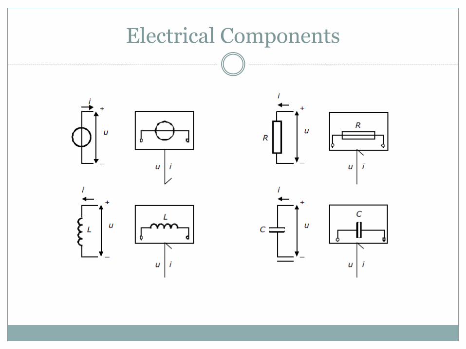
Electrical Components
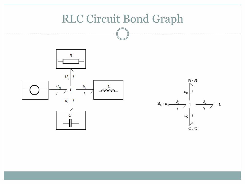
RLC Circuit Bond Graph

Example Two: Mass-Damper-Spring

Mass-Damper-Spring: Bond Graph
Bond Graphs Foundations
The energy flow along a bond has the physical dimension of power, being the product of two variables.
In electrical networks, the two variables are voltage and current. In mechanical systems, the variable pairs are force and velocity for
translation and torque and angular velocity for rotation. In hydraulics, it is pressure and volume flow. For thermodynamic systems, temperature and entropy flow are
used. These pairs of variables are called (power–) conjugated variables.
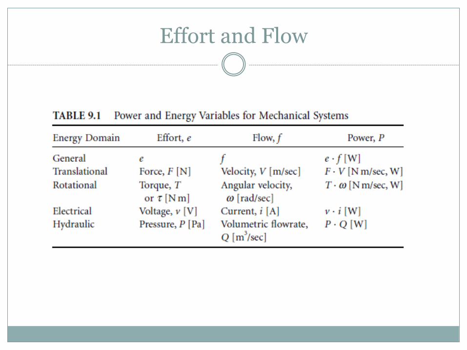
Effort and Flow
Bond Graph Foundations
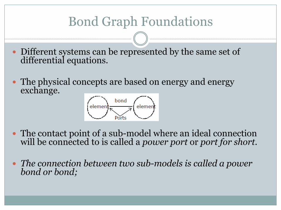
Different systems can be represented by the same set of differential equations.
The physical concepts are based on energy and energy
exchange.
The contact point of a sub-model where an ideal connection will be connected to is called a power port or port for short.
The connection between two sub-models is called a power
bond or bond;
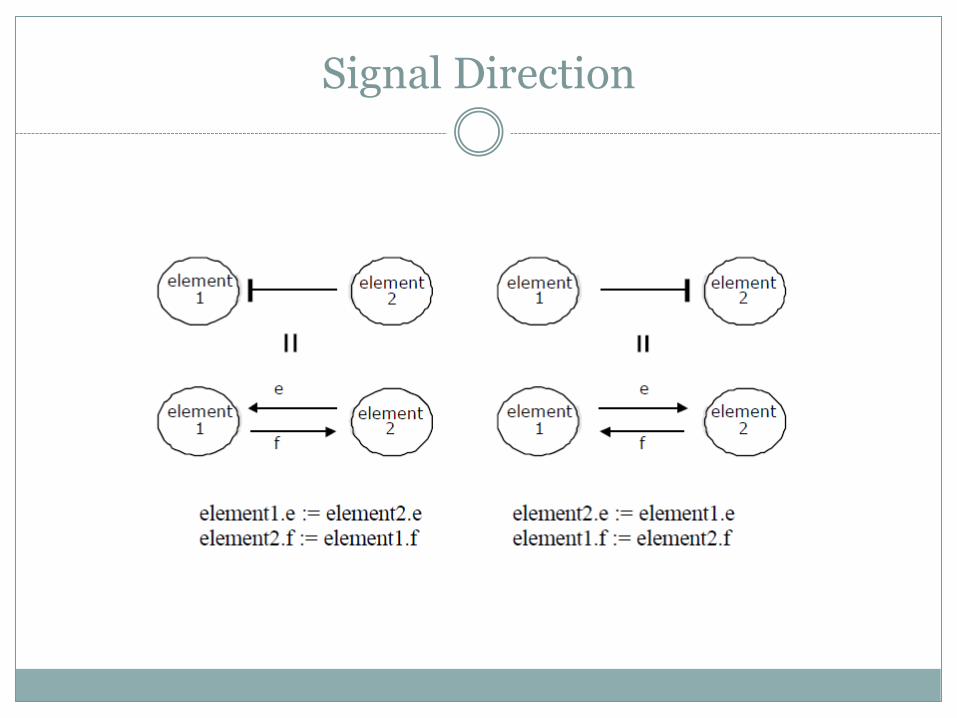
Signal Direction
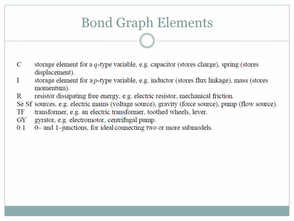
Bond Graph Elements

C elements
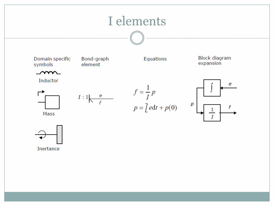
I elements

R elements
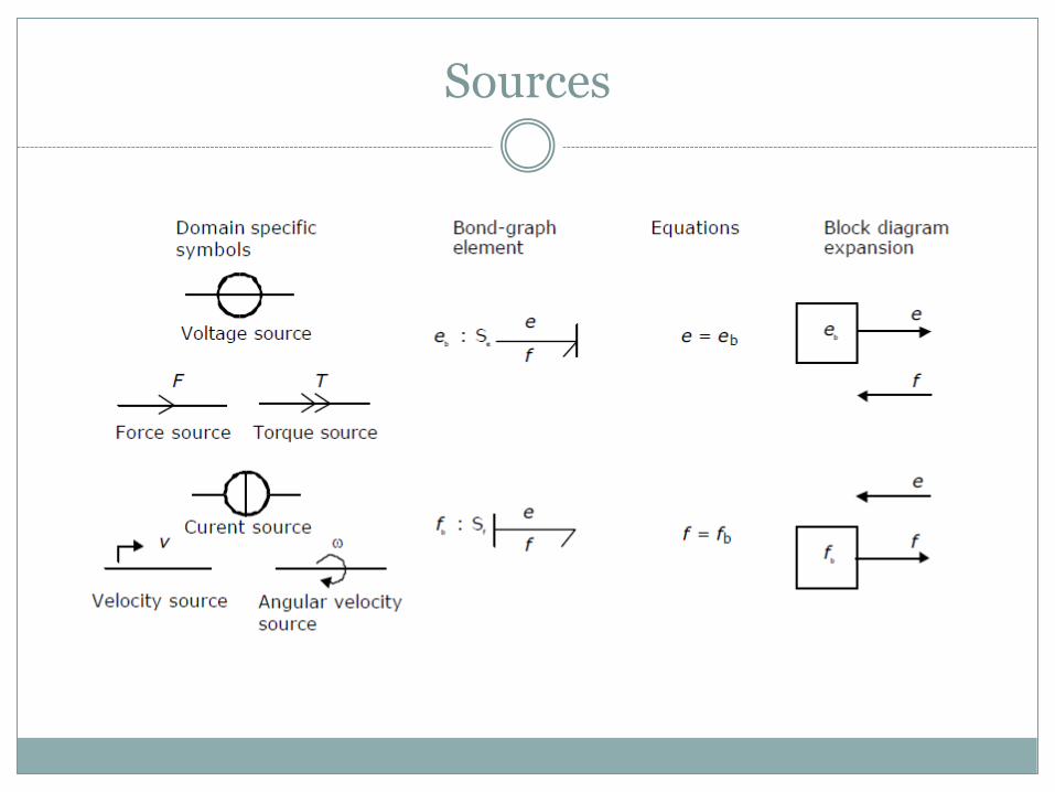
Sources

Transformers

Gyrators
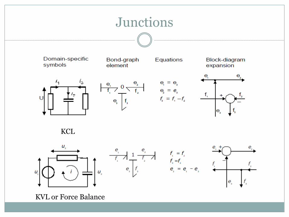
Junctions
KVL or Force Balance
KCL

Simplifications
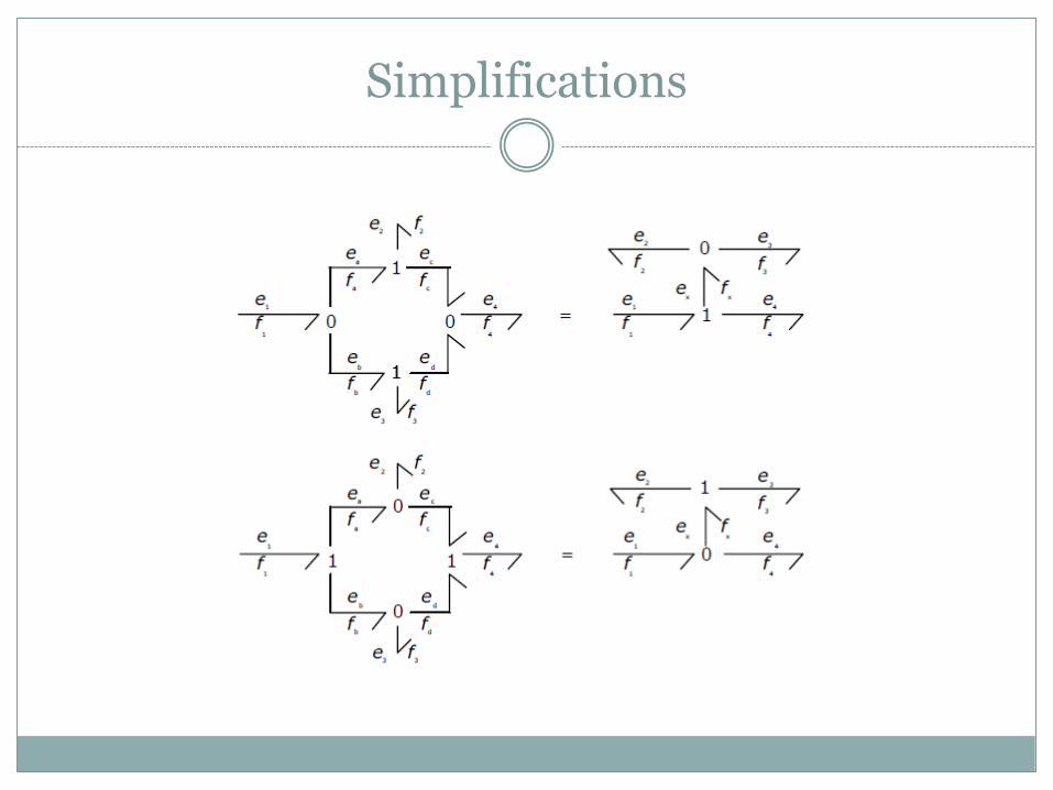
Simplifications
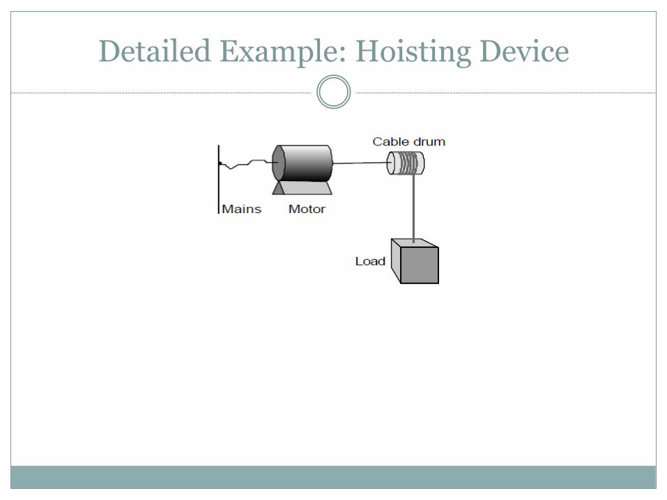
Detailed Example: Hoisting Device

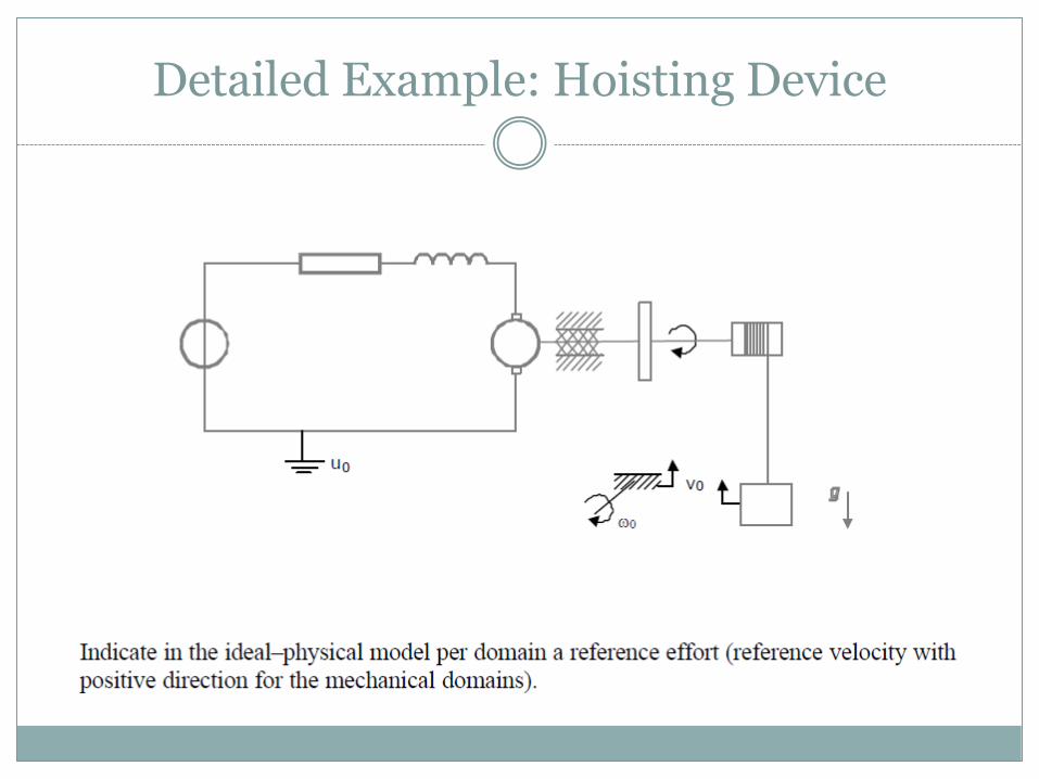
Detailed Example: Hoisting Device
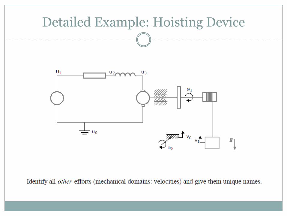
Detailed Example: Hoisting Device
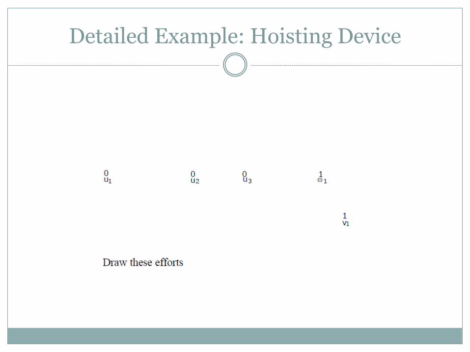
Detailed Example: Hoisting Device
Detailed Example: Hoisting Device

Detailed Example: Hoisting Device
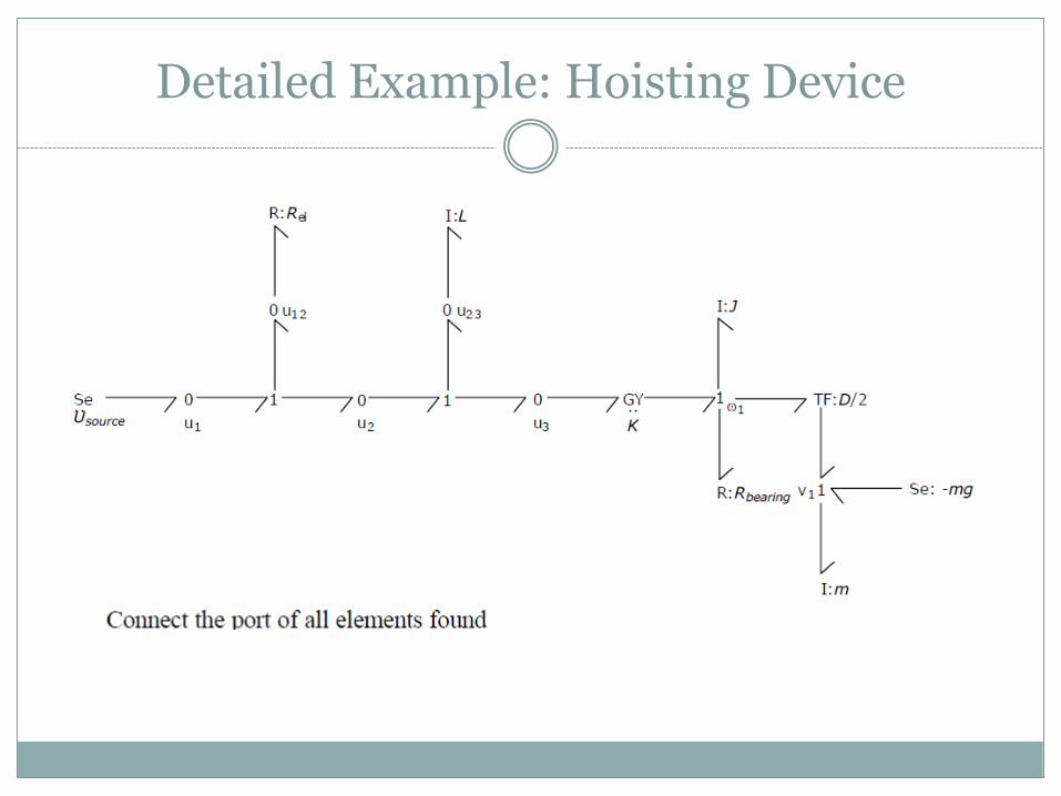
Detailed Example: Hoisting Device
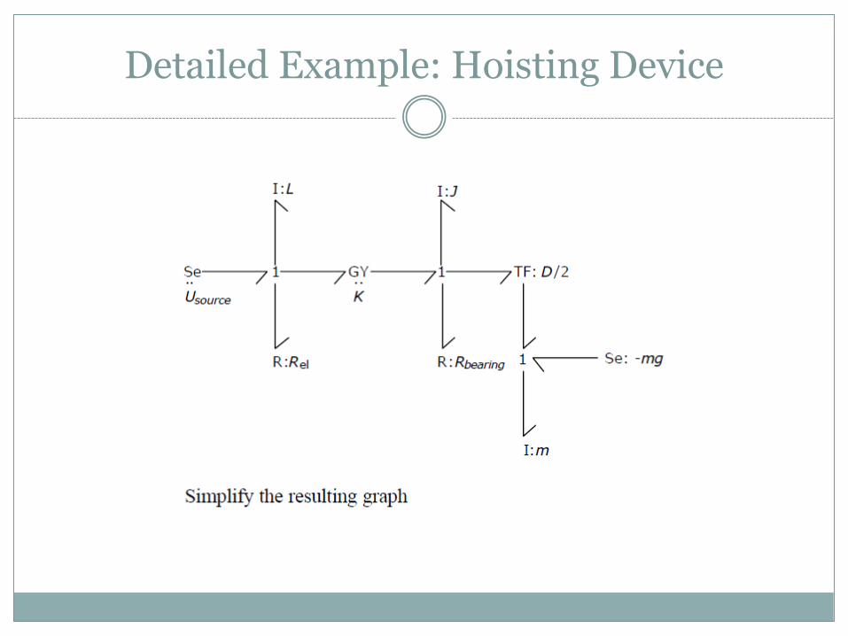
Detailed Example: Hoisting Device

Expansion to Block Diagrams: Hoisting Device

Expansion to Block Diagrams: Hoisting Device
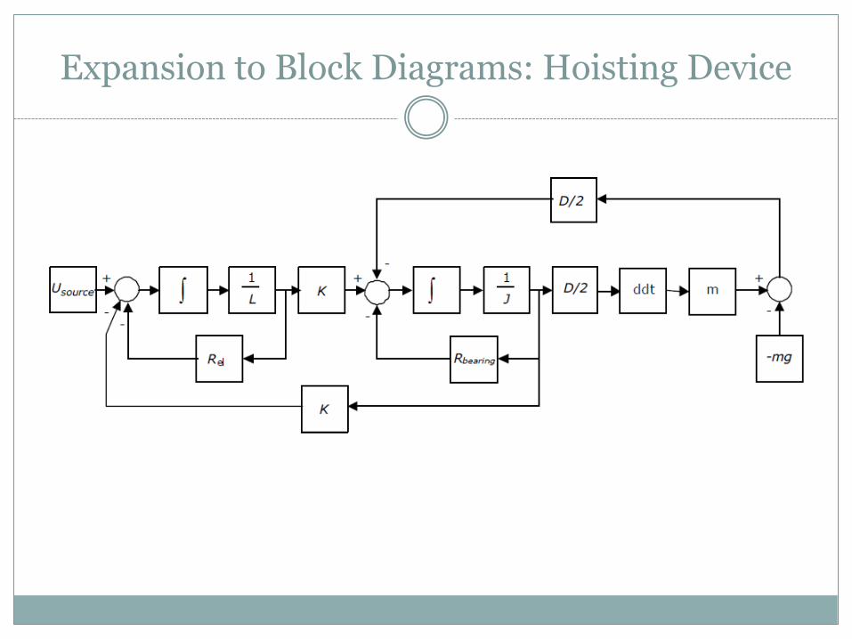
Expansion to Block Diagrams: Hoisting Device
References
Introduction to Physical Systems Modelling with Bond Graphs
Jaan F. Broenink / University of Twente - Netherlands