modeling wind farms for power system stability studies · pdf filethese systems for power...
TRANSCRIPT

Newsletter Issue 95 April 2004
MODELING WIND FARMS FOR POWER SYSTEM STABILITY STUDIES
Yuriy Kazachkov* Executive Consultant [email protected]
Steve Stapleton*
Senior Consultant [email protected]
*On behalf of the Shaw PTI team involved in the wind power model development
Introduction The proper modeling of wind energy projects in system studies is becoming increasingly important to system operators and transmission system owners. The amount of wind generation is growing rapidly and wind farms are growing in size and complexity. Wind farms are being installed consisting of hundreds of units, with the wind farm capable of producing hundreds of MW. The location of a wind farm is selected primarily based on good wind conditions (and, of course, favorable economic and environmental conditions). However these good wind conditions often coincide with relatively remote parts of the power system. Thus the operation of the wind farm and its response to disturbances or other changing conditions on the power system is becoming of increasing concern, especially in cases where the wind farms represent a significant portion of the local generation. These concerns will continue to grow in importance as the amount of wind generation increases. Wind energy conversion systems comprise mechanical and electrical equipment and their controls. Modeling these systems for power system stability simulation studies requires careful analysis of the equipment and controls to determine the characteristics that are important in the timeframe and bandwidth of such studies. Just as important, the characteristics must be reviewed to put aside factors that can be important for wind turbine/wind farm design but do not play a decisive role for the wind turbine/wind farm response from a system standpoint or whose characteristics are not relevant to the frequency range typical for power system stability performance. The objective of this paper is to review and discuss the most significant characteristics and specifics of models of fixed and variable speed wind turbine units and wind farms that are being developed for PSS/E. This paper will not address the detailed mathematics of these models, which have been covered by many papers and other publications.
Overview The key issues in developing a model of any type of equipment is to clearly define its objectives and requirements, that is, what is important for the model to represent and what is not. The wind generator and its controls is a very complex electromechanical system. Although it may be possible to represent all of its functions in detail, this is generally not necessary as many will not be relevant to the subject area of concern.

Power Technology April 2004
Page 2
This paper will describe models that are consistent with two common calculations performed by utility engineers:
Load flow calculations
Transient stability
The objective of a load flow calculation is to determine flows on transmission lines and transformers and voltages on power system buses. This calculation is essential in the planning and design of the interconnection of the wind farm to the system, to ensure that existing equipment is operated within its capabilities and new equipment is properly sized. Such calculations are performed under base case (normal conditions, all equipment generally in service) and contingency conditions (one or more power system elements such as lines, generating units, or transformers out of service). System performance is compared to operating limits and criteria. Such calculations are often performed for different system conditions such as peak load, light load, different seasons, or different power transfer conditions. From the standpoint of the wind farm, these studies are primarily to determine if the generated power can be transmitted successfully to the loads or purchasing entity without loading or voltage problems. The modeling of the ability (or lack of ability) of the wind farm to control voltage through control of the reactive power output of the units is very important as well. The model of the wind farm can be considered to have two potential levels of representation:
A detailed model of the wind farm, representing individual units and the connections between these units and the system. A large wind farm may have over a hundred units. These units are generally spread over a large area, typically connected by a series of feeders. These feeders typically are connected at a “collector” bus which is connected to the power system. The detailed model would thus consist of, say, a hundred or more buses and a similar number of lines. Very detailed data on the system connecting the wind turbine/ generators would need to be supplied by the developer. This data is often not available in the early stages of the planning process. These detailed models can be used to determine voltages and flows within the wind farm, as well as the injection into the utility grid. The model can be used to check/ design voltage control or reactive power strategies in the wind farm. One example of such a strategy is coordination between a central voltage controller and local power factor controllers.
The wind farm can be modeled as seen from the system. Here, the concern is not on the individual wind turbines but on the aggregate effect of the entire farm on the power system. The individual generators are lumped into equivalent machines, generally represented at the collector buses. Thus the size of the system representation of the wind farm is reduced to a few buses and the data requirements are significantly reduced. This level of modeling is often used in system studies where the effects of the injection into the system on system flows and voltages are the concern, and internal wind farm conditions do not need to be determined.
The objective of transient stability studies is to calculate the system response for a defined set of disturbances, typically three phase or single phase faults cleared by tripping of transmission lines. The response of the generators is checked to see that all machines remain in synchronism, damping of power system oscillations is acceptable, and that voltage recovery following fault clearing is adequate. These calculations are also an essential part of the planning and design of the interconnection of the wind farm. Such calculations are performed under different operating conditions, similar to that described above for the load flow studies. The modeling of the dynamics of the wind farm must represent all pertinent effects in the time frame of interest, typically, several seconds following the fault for transient stability analysis. It must also accurately model the response in terms of the frequencies of oscillations seen during such events. Typically, power

Power Technology April 2004
Page 3
system oscillations occur in the bandwidth of about 0.2 to 2 Hertz. The modeling of the ability (or lack of ability) of the wind farm to control voltage in that time frame is also very important. The response of the wind farm, or alternately the model of the wind farm, is very dependent on the type of equipment used. Present equipment designs include:
Doubly fed induction generators (DFIG) with the rotor current controlled by a power converter
Wound rotor induction generators with external resistance controlled by a power converter
Directly connected induction generators
Power converter connected synchronous or induction generators
Models of each of these types of wind turbine generators will be discussed. The model of the wind farm for transient stability studies also can be considered to have the same two potential levels of representation as discussed above for load flow studies:
A detailed model of the wind farm. These detailed models can be used to determine intra-plant dynamics and to check/design voltage control or reactive power strategies in the wind farm.
The wind farm can be modeled as seen from the system. This is the level of modeling normally used in system studies. As noted above, the models must represent the aggregate plant dynamics, including variations (swings) in power output, inertial effects (changes in rotor speed due to power imbalance during and following the fault and synchronizing power effects), and voltage control (ability of the generator to control reactive power output of the machine or plant to maintain terminal or system voltages if applicable). Again, these models need only to model those controls that are significant in the time frame of interest. For example, if pitch or other controls used to adjust for changes in wind speed and direction are slow compared to our few second time frame, they may be considered as constant in the transient stability models.
Other types of studies can be necessary. These include studies of very fast transients, such as those due to lightning or switching surges. The models of the wind turbine generators for these phenomena are quite different and are not addressed here. There are also slower phenomena of concern, such as the potential for voltage flicker or power oscillations caused by wind variation, gusts, etc. The models developed for transient stability studies may be valid in these longer time frames, but may need additions to model the controls that operate over these longer periods and additional data on the wind variations, for example. Modeling Wind Farms for Load Flow Studies The load flow model of a wind farm serves two purposes: as the basis for load flow studies including thermal, voltage and other analyses and as the initial condition for stability analysis. As noted above, there are two choices, a detailed model or a lumped model. In the case of a detailed mode, there is a need to represent many generators and thus a significant amount of data must be entered. For the lumped representation, an equivalent of the wind farm must be created. In either case, an automation of the data entry process is desirable. This automation was accomplished through the development of an IPLAN “Model Builder” program. The Model Builder models the individual or equivalent units with the necessary steady-state parameters and facilitates the addition of individual or equivalent units, along with their step-up transformers, to the power flow case at "collector buses" specified by the user. The user must define the configuration between these collector buses and the system interconnection point. Some of the details of this program are described below.

Power Technology April 2004
Page 4
The real power output of the wind turbine unit is a function of the wind speed seen by the turbine blades as well as the air-density, which is site dependent. For a given air-density, the real power output is related to the wind speed by a power curve which is unique for each type of wind turbine and generally can be supplied by the manufacturer. This curve has been coded into the program for some specific turbines, but can also be inputted from a data file. A portion of the dialog seen in the execution of the Model Builder program is shown below for a test system where four collector buses (bus numbers 102, 105, 107, and 108) are designated for a wind farm interconnection to the system. The program provides options of dispatching units using a specified wind speed or directly to a specified MW value. In terms of reactive power output, the program allows the user to choose between power factor or voltage control. ************************************ PROGRAM WINDTEST MODELING WIND TURBINE GENERATORS AT DESIGNATED COLLECTOR BUSES ************************************ ENTER NAME OF FILE CONTAINING COLLECTOR BUS DATA: CollectorBus_Test.dat A number of collector buses: 4 Equivalent unit on Bus # 102 merges 5 wind turbines Equivalent unit on Bus # 105 merges 7 wind turbines Equivalent unit on Bus # 107 merges 5 wind turbines Equivalent unit on Bus # 108 merges 4 wind turbines ADDING BUS 90102 TO POWERFLOW CASE ADDING BUS 90105 TO POWERFLOW CASE ADDING BUS 90107 TO POWERFLOW CASE ADDING BUS 90108 TO POWERFLOW CASE READING DATA FILE CONTAINING POWER CURVE INFORMATION.. HOW WOULD YOU LIKE TO DISPATCH THE UNITS? 1. USE WIND SPEED AS AN INPUT 2. DISPATCH DIRECTLY Q. EXIT THE PROGRAM ENTER 1 OR 2, OR Q TO QUIT : 1 UNITS WILL BE DISPATCHED ACCORDING TO WIND SPEED SELECT INPUT MODE FOR WIND SPEED: 1. FROM THE TERMINAL 2. FROM A FILE Q. EXIT THE PROGRAM. ENTER EITHER 1, 2 OR Q TO EXIT: 2 ENTER NAME OF FILE WINDSPEED DATA: Wind_Speed_Test.dat Collector Bus #102: average wind speed 10 m/sec, displacement factor 1, azimuth angle 0 ………………………………………………………………………………… Collector Bus #108: average wind speed 10 m/sec, displacement factor 1, azimuth angle 30 Note: The effective wind speed is found as a product of average wind speed, displacement factor, and cosine of azimuth angle. THE EFFECTIVE WIND SPEED AT BUS 102 IS 10.00 M/SEC THE CORRESPONDING OUTPUT FROM EACH UNIT IS 1.210 MW AND THE ROTOR SPEED IS 1440.0 RPM ………………………………………………………………………………… THE EFFECTIVE WIND SPEED AT BUS 108 IS 8.66 M/SEC THE CORRESPONDING OUTPUT FROM EACH UNIT IS 0.790 MW AND THE ROTOR SPEED IS 1269.3 RPM SELECT OPERATING MODE OF WIND FARM: 1. POWER FACTOR CONTROL MODE 2. VOLTAGE CONTROL MODE Q. EXIT THE PROGRAM ENTER 1 OR 2, OR Q TO QUIT: 1 WIND FARM IN POWER FACTOR CONTROL MODE

Power Technology April 2004
Page 5
The same program can be used for calculating and storing other data needed for initialization of the dynamic simulation models. The initialization data flow is shown in Figure 1.
VwAV - average wind speed dw - displacement factor αaz - azimuth angle VWB - effective wind speed βP - pitch angle Vsched - scheduled voltage PF - power factor Taero - mechanical torque from blades PELEC - machine real power QELEC - machine reactive power
Figure 1 - Data flow for initialization of dynamic simulation models
The program can be also used for calculating and writing out the dynamic data to a data file for input to the dynamic simulation program. For example, a recording of measured wind speed as shown in Figure 2 can be read from a file to input the variation in wind speed into the simulation program.
Tmech
Load Flow: EquivalentUnit connected to acollector bus
Wind DynamicModel andPitch Control
Drive TrainDynamicModel
Wind-PowerCurve
RotorSpeed
Dynamic modelsof a generatorand its controls
mechanicalparameters
generator andcontrol parameters
VWB
VwAV
MW output
d wα az βP
VschedorPF
VWB
βP
Initial Rotor Speed
Initial
Initial
PELEC
Q ELEC
Taero

Power Technology April 2004
Page 6
wind speed vs. time
0
5
10
15
20
25
0 1 2 3 4 5 6 7 8 9 10 11 12 13 14 15 16
time (seconds)
win
d s
pee
d (
m/s
)
Figure 2 - Example of measured wind speed to be used for input to the simulation model
Depending on a wind turbine type, the “model builder” program may include different features and provisions for automatic load flow solution. Since some parameters, like the machine reactive power consumption or the power factor correction system reactive power generation, can be sensitive to the terminal voltage, the program may include iterative loops. Especially complicated this iteration procedure becomes for the wound rotor machine with the controlled rotor external resistor. Combining the terminal voltage from the load flow case and desired MW generation, the corresponding MVAR output and rotor speed are calculated. Simultaneously, the total rotor resistance as the sum of the machine and external resistances should be found. A situation is possible when the program is unable to find the combination of MW/MVAR output, rotor resistance and rotor speed. The following plot shows that this task is not straightforward.
0
0.5
1
1.5
2
2.5
3
3.5
0 0.02 0.04 0.06 0.08 0.1 0.12
Slip
MW
1-Rrot=Rmach+Rext10%2-Rrot=Rmach3-Rrot=Rmach+Rext1%
12
3
Figure 3 - MW output of the wound rotor induction machine with external rotor resistors versus rotor slip
Because of this voltage dependency, the load flow case created by the “model builder” for the given dispatch sometimes cannot be accurately used for load flow studies, like contingency analysis, where change of the
Power Technology April 2004
Page 7
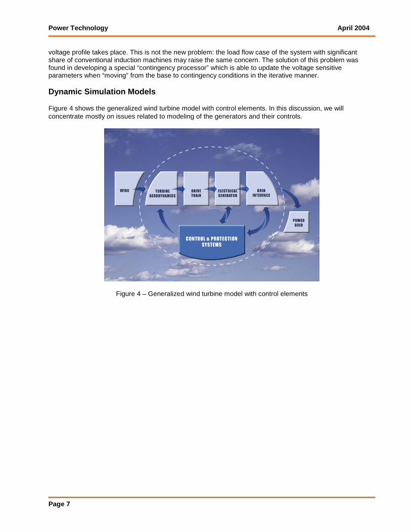
voltage profile takes place. This is not the new problem: the load flow case of the system with significant share of conventional induction machines may raise the same concern. The solution of this problem was found in developing a special “contingency processor” which is able to update the voltage sensitive parameters when “moving” from the base to contingency conditions in the iterative manner. Dynamic Simulation Models Figure 4 shows the generalized wind turbine model with control elements. In this discussion, we will concentrate mostly on issues related to modeling of the generators and their controls.
Figure 4 – Generalized wind turbine model with control elements

Power Technology April 2004
Page 8
Wind model Wind variation can be modeled. The wind model allows two types of variation: a gust or a ramp as shown in Figure 5.
Figure 5 - Simulation of wind gust and ramp
Directly connected induction generator The basic mathematical equations to represent induction motors and generators were developed many years ago. Induction machines have been modeled in transient stability programs using these relationships for many years. There has been an on-going discussion on the level of detail needed to simulate electrical machines for stability studies. It has been generally accepted that, accounting for the respective bandwidth, the dynamics associated with the stator winding can be ignored, and only flux linkage dynamics and mechanical movement (inertial dynamics) need to be accounted for. However there are concerns regarding the accuracy of reproducing the dc offset in stator currents and the related breaking torque during faults and after fault clearing. This consideration has caused an appeal for using full-order models of induction machines rather than the reduced order models available in the dynamic libraries of commercial software packages. It is evident that, even in case of using full-order models, the accuracy of simulating the dc offset is undermined by the fact that these software packages represent the transmission network by algebraic, not differential, equations.

Power Technology April 2004
Page 9
Investigations were made to demonstrate the effect of the level of modeling detail on the response of an induction machine to a nearby three phase fault. Figure 6 compares the terminal current of an induction machine in response to a 3-phase fault and its clearing for three sets of simulation tools applied to the same network topology and conditions:
A 3-phase electromagnetic simulation program with full-order models of the network (differential equation model) and the machine (including stator flux transients)
A commercial stability program with a full-order induction machine model but the typical algebraic network model
A commercial stability program with the standard reduced order induction machine model (no stator flux transients). This is the standard representation generally available in stability programs today.
Figure 6 - Induction Generator Terminal Current for different simulation tools
The three-phase electromagnetic simulator produces, of-course, 3-phase currents. To be compared with the stability program output, these currents have been converted into a “peak value” using a conversion formula as follows:
)(3
2 222cbapeak iiiI ++=

Power Technology April 2004
Page 10
Figure 6 clearly shows that:
The standard dynamic model provides a good reproduction of the average current component
A combination of the standard stability program and the full-order induction machine model does not provide additional accuracy in the simulation of the dc offset in the machine terminal current. If this component and the related torque are of concern, a three phase electromagnetic simulation program should be used.
Doubly-fed (wound rotor) induction generator In a doubly-fed induction generator, the rotor current or voltage can be controlled using power electronics, generally in terms of both magnitude and frequency. This gives a much greater degree of controllability to the induction generator, including the potential for control of reactive power. Different levels of modeling DFIG may be needed depending on the rotor controls employed by the manufacturer. Representative models have been developed for several strategies.
A sixth order model of the single cage DFIG and an eighth order model of the double cage DFIG, with all stator and rotor electrical and mechanical dynamics taken into account. It is noteworthy that there are doubts regarding the practicality of the double cage concept to wind turbine units where a wide range of operating rotor slips is inherent. These models use rotor voltage real and imaginary components in a synchronously rotating reference frame as inputs from the controller. Stator voltage:
)2(
)1(
RbIaI
I
IbRaR
R
Irdt
dE
Irdt
dE
Ψ+−Ψ
=
Ψ−−Ψ
=
ω
ω
Here ωb is the base angular frequency in p.u. with respect to synchronous speed. It is introduced for generality. For most studies, ωb =1. Rotor voltage:
)4()(
)3()(
1
1
RbmII
I
IbmRR
R
irdt
de
irdt
de
λωωλ
λωωλ
−−+=
−++=
Here ωm is the rotor mechanical angular speed in p.u. with respect to synchronous speed.
Both components of the rotor voltage are constant in steady state, the same way as d and q components of the synchronous machine stator voltage. In the course of the dynamic simulation, eR and eI are subject to control. Changing eR and eI actually means changing a magnitude and a frequency of the physical rotor three-phase voltage.

Power Technology April 2004
Page 11
Real and imaginary components of flux linkages as functions of currents do not interact, so they can be written without indices as:
)7(
:
)6()(
:
)5(
:
1 m
mm
ma
iL
LinkageFluxRotorWound
IiL
LinkageFluxMutual
IL
LinkageFluxStator
Ψ+=
−=Ψ
Ψ+−=Ψ
λ
From the latter equations rotor current can be expressed as a function of the stator current and rotor flux linkage:
)8(1LL
ILi
m
m
+
+=
λ
Differential equations written above for the single cage machine will be supplemented by the mechanical equation for the rotor speed deviation:
H
DAMPTT
dt
d bmelmechbm 2
*)()(
ωωωω −−−=−
Figure 7 compares the simulations of the response of a generator to a fault using both the single cage DFIG model and the standard PSS/E induction generator model (CIMTR3). The former model operates with zero rotor voltage to reproduce the conditions of the latter model. One can see the fundamental frequency component resulting from the dc offset caused by the fault.

Power Technology April 2004
Page 12
Figure 7 - Generator response to a fault - full-order model of DFIG versus reduced order model.
A fourth order model of the single cage DFIG which uses rotor current, not rotor voltage, as the
controlled variable. This fits the wind turbine control philosophy where controls process a command in terms of the rotor current in a very fast manner supported by high frequency PWM power electronics. The rotor current follows this command with a negligible delay. This type of control is sometimes referred to as vector control. The rotor current command from the controls is formed with respect to a reference frame rotating together with the stator flux vector. From equations (5), (6), (7) above, the rotor flux linkage is an algebraic function of the stator flux linkage, stator and rotor currents. If the rotor current is given the differential equations for the rotor flux linkage are not needed, and the order of the model is reduced by two.
A second order dynamic DFIG model, following the philosophy used for decades for power electronics related dynamic models including HVDC and FACTS devices, where the power electronics and resulting dynamics are so fast that they can be represented in a transient stability program by algebraic equations instead of differential equations. That is, their time dynamics are instantaneous from the viewpoint of this time frame. This model has been developed and is being tested. This model ignores the stator and rotor electrical dynamics, using the steady state algebraic equations, but respects the mechanical dynamics of the rotor. It uses commands in terms of desired total real and reactive power as inputs from the controller. This approach is based on the modeling recommendations of a manufacturer of wind turbines employing DFIG with rotor control by means of a power converter. Figure 8 illustrates the response of this model to a fault. Real and reactive power closely follows the respective commands from the controls, although subject to some limitations. Since the machine model calculates all the stator and rotor variables, a user has an access to stator and rotor currents. However this kind of a machine model has a limitation in terms of credible representation of the transient stator and rotor current components. Sometimes it can be important, for example when the

Power Technology April 2004
Page 13
rotor current protection should be modeled. However, closer familiarization with the practical implementation shows that, before entering the protection system, the rotor current signal is processed through the low frequency filters. This makes the algebraic approach combined with the proper filtering more feasible.
For technologies employing the wound rotor induction machine with the rotor connected to the controlled external resistor, the challenge is to find at each integration step the value of the total rotor resistance Rrot which yields the given terminal voltage, desired electrical power, and a rotor slip. It is implemented in a way of very precise iterations using well known algebraic equations of the equivalent circuit of the induction machine.
All of the above DFIG models are initialized from the total generator MW and MVAR specified in the load flow, along with the rotor slip, by using an iterative solution in terms of the stator real power. These models were successfully tested with an integration step of a quarter cycle of the fundamental frequency. Synchronous or Induction Generator Decoupled from the Grid by a Power Converter In this configuration, the interface with the utility is a power converter. Under transients, the frequency of the line-side converter current will follow the utility voltage frequency, hence, the unit remains in synchronism with the grid. Both real and reactive power generation and their combination are subject to limits related to the power converter rating and/or limits imposed by the generator and the drive train. For studying the impact on the grid, a governor model is not needed as speed is controlled only by the power electronics.
Figure 8 - Generator response to a fault with a second order DFIG model

Power Technology April 2004
Page 14
Under/over voltage – frequency protection In many wind farm designs, the controls incorporate protection that trips the generators when voltage or frequency deviates outside a band, either employing fixed deviation thresholds or more complex logic such as inverse voltage characteristics. This often results in the tripping of the wind farm for any faults in the neighborhood of the interconnection point. With the amount of wind generation growing to a more appreciable share of local generation, such a philosophy of tripping for nearly all nearby disturbances is being readdressed, and protection systems are becoming more sophisticated. Generally, voltage and frequency are monitored either at the terminal bus or the collector bus and the protection exercises several threshold levels. Dynamic models of such protection systems have been developed.
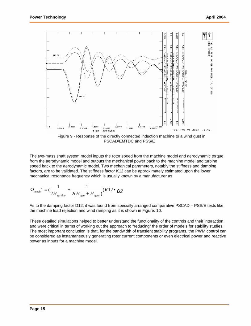
Model Validation The models described above were validated by comparison of the response of these models to the response of more detailed, higher-bandwidth models created in a parallel effort by Electrotek Corporation for use with the PSCAD/EMTDC program. As an example, the next two plots compare the PSS/E and PSCAD response of the wind turbine using a directly connected induction machine to the wind gust.
Power Technology April 2004
Page 15
Figure 9 - Response of the directly connected induction machine to a wind gust in
PSCAD/EMTDC and PSS/E The two-mass shaft system model inputs the rotor speed from the machine model and aerodynamic torque from the aerodynamic model and outputs the mechanical power back to the machine model and turbine speed back to the aerodynamic model. Two mechanical parameters, notably the stiffness and damping factors, are to be validated. The stiffness factor K12 can be approximately estimated upon the lower mechanical resonance frequency which is usually known by a manufacturer as
ωngeargenturbine
mech KHHH
•+
+=Ω 12))(2
1
2
1(2
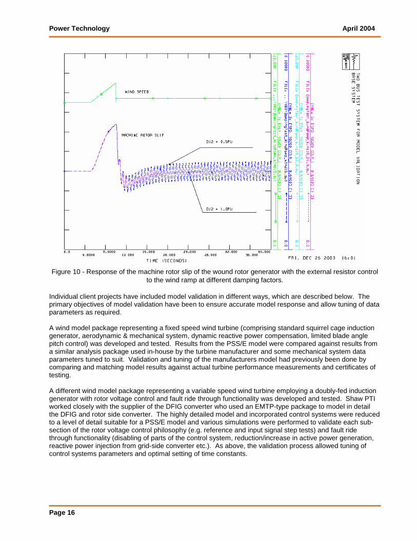
As to the damping factor D12, it was found from specially arranged comparative PSCAD – PSS/E tests like the machine load rejection and wind ramping as it is shown in Figure. 10. These detailed simulations helped to better understand the functionality of the controls and their interaction and were critical in terms of working out the approach to “reducing” the order of models for stability studies. The most important conclusion is that, for the bandwidth of transient stability programs, the PWM control can be considered as instantaneously generating rotor current components or even electrical power and reactive power as inputs for a machine model.
Power Technology April 2004
Page 16
Figure 10 - Response of the machine rotor slip of the wound rotor generator with the external resistor control
to the wind ramp at different damping factors. Individual client projects have included model validation in different ways, which are described below. The primary objectives of model validation have been to ensure accurate model response and allow tuning of data parameters as required. A wind model package representing a fixed speed wind turbine (comprising standard squirrel cage induction generator, aerodynamic & mechanical system, dynamic reactive power compensation, limited blade angle pitch control) was developed and tested. Results from the PSS/E model were compared against results from a similar analysis package used in-house by the turbine manufacturer and some mechanical system data parameters tuned to suit. Validation and tuning of the manufacturers model had previously been done by comparing and matching model results against actual turbine performance measurements and certificates of testing. A different wind model package representing a variable speed wind turbine employing a doubly-fed induction generator with rotor voltage control and fault ride through functionality was developed and tested. Shaw PTI worked closely with the supplier of the DFIG converter who used an EMTP-type package to model in detail the DFIG and rotor side converter. The highly detailed model and incorporated control systems were reduced to a level of detail suitable for a PSS/E model and various simulations were performed to validate each sub-section of the rotor voltage control philosophy (e.g. reference and input signal step tests) and fault ride through functionality (disabling of parts of the control system, reduction/increase in active power generation, reactive power injection from grid-side converter etc.). As above, the validation process allowed tuning of control systems parameters and optimal setting of time constants.

Power Technology April 2004
Page 17
PSS/E Software Packages Developed for Wind Power Applications
1. Wind Turbine Employing Induction Generator Directly Connected to the Grid – NEG Micon NM72 1.5 MW 60 Hz, NM72 1.65 MW 50 Hz, Bonus 1.3 MW 60 Hz, Bonus 2.3 MW 50 Hz and Bonus 1.3 MW 50 Hz.
2. Wind Turbine Employing Doubly – Fed Induction Generator with Active Rotor Control by means of Power Converter – DFIGDC for BIWTP/WEJRG (generic),GE 1.5 MW 50 and 60 Hz, GE 3.6 MW 50 and 60 Hz, Gamesa G80 2.0 MW 50 Hz, Nordex N80 2.5 MW 50 Hz, RePower 50Hz MD70 & MD77 1.5MW, MM70 & MM82 2MW.
3. Wind Turbine Employing Wound Rotor Induction Generator with Passive Rotor Control by means of External Resistors – Vestas V80 1.8 MW and V47 0.66 MW 60 Hz, Gamesa G80 1.8 MW 60 Hz.
4. Wind Turbine Employing Induction Generator Decoupled from the Grid by a Power Converter (Static Interface) – Kenetech 0.4 MW 33-MVS as a prototype.
5. Wind Turbine Employing Synchronous Generator Decoupled from the Grid by a Power Converter – Enercon E-66 1.8MW.
All dynamic simulation models included into these packages are written as user’s models. Shaw PTI is planning to have models standardized for one of the closest PSS/E releases.