modeling thermal convection in supradetachment basins: example
TRANSCRIPT
Modeling thermal convection in supradetachment basins:example from western Norway
A. SOUCHE*, M. DABROWSKI AND T. B. ANDERSEN
Physics of Geological Processes (PGP), University of Oslo, Oslo, Norway
ABSTRACT
The juxtaposition of fault-bounded sedimentary basins, above crustal-scale detachments, with warmer exhumed
footwalls can lead to thermal convection of the fluids in the sediments. The Devonian basins of western Norway
are examples of supradetachment basins that formed in the hanging wall of the Nordfjord-Sogn Detachment
Zone. In the central part of the Hornelen and Kvamshesten basins, the basin-fill is chiefly represented by fluvial
sandstones and minor lacustrine siltstones, whereas the fault margins are dominated by fanglomerates along the
detachment contact. Prominent alteration and low-greenschist facies metamorphic conditions are associated with
the peak temperature estimates of the sediments close to the detachment shear zone. Fluid circulation may have
been active during the burial of the sediments, and we quantify the potential role played by thermal convection in
redistributing heat within the basins. Different models are tested with homogeneous and layered basin-fill and with
material transport properties corresponding to sandstones and siltstones. We found that thermally driven fluid flow
is expected in supradetachment basins as a transient process during the exhumation of warmer footwalls. We
demonstrate that the fluid flow may have significantly affected the temperature distribution in the upper five kilo-
meters of the Devonian basins of western Norway. The temperature anomaly induced by the flow may locally
reach about 80°C. The sedimentary layering formed by sand- and siltstones strata does not inhibit fluid circulation
at the scale of the basin. The presence of fluid pathways along the detachment has an important impact on the
flow and allows an efficient drainage of the basin by channelizing fluids upward along the detachment.
Key words: Devonian basins Norway, groundwater flow, Nordford-Sogn Detachment Zone, sedimentary layers,
shear zone, temperature anomaly, thermal convection
Received 21 April 2013; accepted 28 April 2013
Corresponding author: Alban Souche, Physics of Geological Processes (PGP), University of Oslo, P.O. Box 1048,
Blindern, 0316 Oslo, Norway.
Email: [email protected]. Tel: +47 63 80 66 54. Fax: +47 63 81 63 56.
*Present address: Institute for Energy Technology (IFE), Environmental Technology, P.O. Box 40, 2027, Kjeller,
Norway
Geofluids (2013)
INTRODUCTION
Fluid flow in sedimentary basins can play a major role in
redistributing mass and heat in the system (Wood & Hew-
ett 1982; Person et al. 1996). It can be driven by several
factors such as the surface topography, the compaction of
the sediments, or buoyancy instabilities of the fluid(s).
Topography-driven flow may control the circulation of
meteoritic water through aquifers when recharge areas are
located at higher elevation than discharge areas. This type
of flow can result, for example, in the occurrence of ther-
mal springs in mountainous areas (Andrews et al. 1982;
Levet et al. 2002; Brumm et al. 2009). Compaction-driven
flow operates with a limited amount of fluids initially
trapped within the sediments. During burial, the expelled
fluids may transport solutes and cause precipitation of min-
erals within various units of the sedimentary basin (Bjør-
lykke & Høeg 1997; Bjørlykke 1999). Buoyancy-driven
flow is induced by variations of the fluid density within
porous media. The density increase resulting from dissolu-
tion of CO2 into brine may lead to convective flow and
storage of CO2-rich brine in deep part of saline aquifers
(Hidalgo & Carrera 2009; Pau et al. 2010).
This study focuses on buoyancy-driven flow induced by
the thermal expansion of a fluid (water) when heated. This
process, referred as thermal convection or free convection
in sedimentary basins, is driven by basal heating and lateral
thermal gradient. Analog experiments of Rayleigh–B�enard
© 2013 John Wiley & Sons Ltd
Geofluids (2013) doi: 10.1111/gfl.12042

thermal convection in fully saturated porous media docu-
ment the onset of instability in terms of the critical Ray-
leigh number (Elder 1967; Combarnous & Bia 1971;
Palm et al. 1972). Depending on the boundary conditions,
the value of the critical Rayleigh number can vary from 27
in the case of a permeable surface to 39 in the case of an
impermeable surface (McKibbin & O’Sullivan 1981).
Thus, in a horizontally stratified basin where a permeable
sandstone aquifer is embedded in impermeable shale, the
critical Rayleigh number of the system is 39, which corre-
sponds roughly to a minimum aquifer thickness of 330 m
with permeability of 1 Darcy under a geothermal gradient
of 30°C km�1 (Bjørlykke et al. 1988). As suggested by
Bjørlykke et al. (1988), such thick permeable units might
be rare in most sedimentary basins. However, this point of
view is partially biased by the binary mode of heat transfer
suggested by the Rayleigh–B�enard experiment (i.e., either
conduction below the critical Rayleigh number or conduc-
tion with convection above the critical Rayleigh number).
In a geological setting where the layers and the isotherms
may be tilted or slanted (Fig. 1), it is misleading to apply
the predictions obtained with a Rayleigh–B�enard setup
where the boundary temperature conditions remain per-
fectly horizontal. The horizontal component of the tem-
perature gradient leads unconditionally to fluid motion in
permeable rocks, even below critical Rayleigh number
(Combarnous & Bia 1971; Bories & Combarnous 1973;
Bjørlykke et al. 1988; Gouze et al. 1994; Wangen 1994,
1997; Simms & Garven 2004). This type of fluid motion
is called non-Rayleigh convection, as opposed to Rayleigh
convection above critical Rayleigh number (Fig. 1).
In the case of a crustal-scale detachment and suprade-
tachment basins addressed in this article, sedimentary
basins may be in contact with potentially high permeable
strata and conduits along fault margins. Transient thermal
effects like heating of the basin from the progressive exhu-
mation of a ‘hot’ footwall and shear heating in the detach-
ment shear zone may have large effects on the fluid flow
potential in sedimentary basins (Souche et al. 2012b).
High peak temperature conditions were estimated close to
the detachment fault in the supradetachment basins of wes-
tern Norway (Svensen et al. 2001; Souche et al. 2012a).
The high temperature conditions could have resulted from
the conductive heating of the basin adjacent to the warmer
exhumed footwall. The conditions could also arise from
the circulation of hot fluids in the basin and along the
detachment zone. We consider the specific geological set-
ting of the post-Caledonian detachment zone in western
Norway, which is geologically constrained both from the
thermobarometric and geochronological studies of the
footwall (e.g., Labrousse et al. 2004; Hacker et al. 2010)
and from the architecture of the supradetachment basins in
the hanging wall (e.g., Osmundsen & Andersen 2001).
We investigate whether the slanted isotherms, produced by
the exhumation of the footwall during the extension, could
lead to significant fluid flow in the supradetachment basins.
Finally, we quantify the temperature anomaly induced by
the fluid circulation in the sediments and evaluate its
(A)
(B)
Fig. 1. (A) Rayleigh–B�enard experiments in
porous media and expected type of fluid
convection. In the case of perfectly horizontal
isotherms, fluid flow only occurs after the
onset of convection above the critical
Rayleigh number. In the case of slanted
isotherms, fluid flow will always occur due to
the horizontal component of the thermal
gradient. The fluid motion below the critical
Rayleigh number is known as non-Rayleigh
convection. (B) Sketch of a crustal
detachment with supradetachment basins at
the surface. The exhumation of the footwall
and the burial of the hanging wall may,
respectively, lead to the rise and depression
of the isotherms in the area. The resulting
slanted isotherms may control the fluid flow
in the supradetachment basins.
© 2013 John Wiley & Sons Ltd
2 A. SOUCHE et al.

impact on the peak temperature conditions of the sedimen-
tary basins.
These questions are of particular interest in understand-
ing the thermal evolution of the Devonian basins of wes-
tern Norway but also, with a broader perspective, relevant
particularly for the thermal evolution of half-graben basins
that have a characteristic tilt of the sedimentary layers.
GEOLOGICAL SETTING
The Nordfjord-Sogn Detachment Zone
The Nordfjord-Sogn Detachment Zone (NSDZ) is a crus-
tal-scale extensional detachment that formed during gravi-
tational collapse and dismantlement of the Caledonian
orogeny in the Early to Late Devonian (Norton 1986; Ser-
anne & Seguret 1987; Seguret et al. 1989; Andersen &
Jamtveit 1990; Andersen 1998; Osmundsen et al. 1998).
The NSDZ juxtaposes lower Devonian (approximately
415–400 Ma) high- to ultra-high-pressure rocks in its
footwall (Hacker et al. 2010) with sedimentary rocks of
nearly the same age in its hanging wall (Fig. 2A). The
regional extension was accommodated by strike-slip and li-
stric-normal faulting at the surface, which controlled the
sedimentary architecture of the supradetachment basins
(Osmundsen et al. 2000).
The exhumation of the footwall of the NSDZ is docu-
mented by a number of tectonic and petrological studies of
the eclogite-facies Western Gneiss Region (WGR; Hacker
et al. 2003; Labrousse et al. 2004; Root et al. 2005; John-
ston et al. 2007; Kylander-Clark et al. 2009; Young et al.
2011). The pressure-temperature-time evolution of the
footwall indicates that the decompression, corresponding in
some area to exhumation >100 km, occurred in a time win-
dow of 5–10 Myr (Andersen & Jamtveit 1990; Hacker
et al. 2003; Young et al. 2011). The Caledonian nappes of
the Hyllestad complex below the Solund basin (Fig. 2A),
and the Lykkebø/Eikefjord groups below the Hornelen
basin, recorded high-pressure metamorphism in the range
of 10–15 kbar (approximately 60 km burial) with peak
temperatures of 550–600°C (Hacker et al. 2003; Johnston
et al. 2007). These units are separated from the basins by a
mylonitic shear zone with an average shear strain of c ≥ 20
(Andersen & Jamtveit 1990; Hacker et al. 2003; Marques
et al. 2007). A simple reconstruction of a normal-sense
shear zone with a dip of 30° and a thickness of 5 km results
in the vertical displacement of 50 km, which is compatible
with the geological observations and the exhumation of the
HP Caledonian nappes.
Formation of the Devonian supradetachment basins
The most prominent geological feature of the Devonian
basins is their tectonically controlled architecture (Bryhni
1964; Steel et al. 1977; Folkestad & Steel 2001). The
basins developed in a continental setting characterized by
debris flows, high-energy fluvial processes, and high sedi-
mentation rate (>2.5 mm per year; Nilsen & McLaughlin
1985). Their architecture and geometry was controlled by
the motion above extensional listric-normal faults beneath
the basins (Osmundsen & Andersen 2001). Along the fault
margins, the basins are filled with fanglomerates formed by
proximal debris flows and alluvial fans (Fig. 2E), and they
are filled with distal fluvial and lacustrine deposits in their
central parts. In the central part of the Hornelen basin
(Figs 2A), the bedding exhibits a relatively constant east-
ward tilt of approximately 30° dipping toward the detach-
ment fault. Each depositional unit is typically close to
100 m thick and comprises rhythmic deposition of cyclo-
thems (Fig. 2B). These cyclothems consist of prograding
coarsening-up-fining sequences with sedimentary facies
varying from finer sand- and siltstones to conglomerates
(Figs 3). Within the Hornelen basin, this pattern repeats
itself more than 100 times resulting in about 25 km of
preserved stratigraphic thickness (Steel et al. 1977).
However, the burial depth has not exceeded 10–14 km
(Svensen et al. 2001), and the stratigraphic thickness accu-
mulated by lateral growth during episodic eastward shifts
of the depocenter in response to tectonic motions
(Fig. 2E). Similar tectonic control on deep basins have
been described from the Ridge basin in California
(13.5 km of dominantly continental formation), which has
been proposed as a more recent example to the sedimenta-
tion along the north margin of the Hornelen basin (Nilsen
& McLaughlin 1985).
Contemporaneous with the main E-W extension, N-S
shortening affected western Norway giving rise to overall
transtension (Krabbendam & Dewey 1998; Osmundsen &
Andersen 2001). The N-S shortening resulted in large-
scale folding of the sedimentary strata around E-W fold
axis, and in the characteristic present-day saucer-shape
geometry of the basins and detachment mylonites
(Fig. 2A,D).
The peak temperature conditions of the basins have been
documented from authigenic minerals and fluid-inclusion
studies by Svensen et al. (2001) and by Raman spectros-
copy on organic carbon by Souche et al. (2012a). The
highest temperatures within the basins are found close to
the detachment fault. Locally, the sediments were exposed
to temperatures of 345°C, corresponding to a geothermal
gradient as high as 37°C km�1 during the exhumation of
the metamorphic basement.
The basin-detachment contact
The contact between the Devonian sediments and the
shear zone of the extensional detachment typically occurs
along a sharp geological boundary (Fig. 4). The brittle
© 2013 John Wiley & Sons Ltd
Thermal convection supradetachment basins Norway 3

contact between the sediments and the mylonitic shear
zone is represented by a 1–2 m thick gauge zone, filled
with calcite and late open fractures. Multiple generations
of cataclasite and pseudotachylyte are observed along the
Solund fault (Fig. 4B), on outcrop, and thin-section scales,
suggesting recurrent brittle movements along the fault
(A)
(C)(D)
(E)
(B)
Fig. 2. (A) Simplified geological map showing the location of the supradetachment basins and the crustal-scale Nordfjord-Sogn Detachment Zone (NSDZ) in
western Norway. (B) Stratigraphic log along the path A′–A″ in the central part of the Hornelen basin modified from Steel et al. (1977). (C) Schematic recon-
stitution of the Caledonian collision between Laurentia and Baltica. The black star illustrates the HP burial conditions of the Caledonian nappes exposed today
in the shear zone of the NSDZ. (D) Schematic illustration of the formation of the Devonian basins above the NSDZ. (E) A simplified cross-section across the
Devonian basins.
© 2013 John Wiley & Sons Ltd
4 A. SOUCHE et al.

plane, similar to those described along the Kvamshesten
basin (Braathen et al. 2004). Several segments of the
basin-bounding faults have experienced minor brittle post-
depositional reactivation as documented by Torsvik et al.
(1992).
Few meters below the contact, the rock belongs to the
shear zone of the detachment and exhibits extreme mylon-
itic fabrics (Fig. 4C). The foliation shows a striking align-
ment with the main fault. The schistosity and friability of
the mylonites can potentially allow fluid circulation within
the upper part of the shear zone.
Few meters above the contact, sheared conglomerates
mark the structural base of the Solund basin (Fig. 4A). In
some places, the deformation overprints the sedimentary
structure and brings uncertainties regarding the protolith
of the fault rocks (Fig. 4A). These highly sheared and frac-
tured rocks commonly have a large number of quartz frag-
ments that could be either detrital or derived from
fragmented veins.
Evidence for fluid activity
The sedimentary rocks in the Devonian basins of western
Norway show a series of diagenetic and metamorphic alter-
ations that reflect the activation of fluid processes during
the burial of the sediments (Seranne & Seguret 1987;
Odling & Larsen 2000; Svensen et al. 2001; Beinlich et al.
2010). The maximum burial was marked by the formation
of locally dense network of metamorphic veins (Svensen
et al. 2001). The veins host authigenic mineral such as epi-
dote, chlorite, biotite, and local actinolite that give con-
strains on the peak temperature conditions of the
sediments. The density of veins increases toward the
detachment contact. Two examples of such network are
presented in Fig. 5B,C.
The common presence of carbonate in outcrop-scale
veins and in former pore-space on the thin-section scale
documents a fluid activity in the sediments. The precipita-
tion of carbonate resulted in the clogging of the primary
(A) (B)
Fig. 3. Examples of sediments found in the
Devonian basins of western Norway. (A)
Coarse conglomerates in the Solund basin.
(B) Red sandstones and conglomerates in the
Solund basin, near Liavika.
(B)
(A)
(C)
Fig. 4. Fault zone (B) between the Solund
basin (A) and the mylonitic shear zone of the
detachment (C), picture taken near
Tistelklubben. (A) Sheared conglomerates few
meters above the detachment contact, near
Tistelklubben. (B) Gauge from the cataclastic
zone, near Losnedalen. (C) Mylonitic texture
of the shear zone, few meters beneath the
detachment contact, near Tistelklubben.
© 2013 John Wiley & Sons Ltd
Thermal convection supradetachment basins Norway 5

porosity that does not permit in situ measurements of the
porosity or the permeability of the sediments.
Alteration including carbonatization of ultramafic clasts
in the Solund basin occurred in situ during the burial of
the sediments (Beinlich et al. 2010). In conglomeratic
lithologies where ultramafic clasts may constitute up to
20% of the sediments, the surrounding matrix is also
altered (Fig. 5A). The widespread alteration of the ultra-
mafic clasts together with the matrix of the conglomerates
demonstrates a pervasive interaction between the clastic
material and a pore fluid circulation in the basin (Beinlich
et al. 2010). A similar conclusion regarding pervasive fluid
flow in the basins has been suggested to account for the
oxidation of detrital carbonaceous material associated with
the recurrent presence of hematite in the matrix of the sed-
iments (Souche et al. 2012a).
MODEL SETUP
Lithospheric- and basin-scale configurations
The background temperature, which is a necessary parame-
ter in our basin-scale fluid flow model, is obtained by mod-
eling the thermal evolution of a crustal-scale detachment in
a lithospheric-scale model of the NSDZ (Fig. 6A,B),
referred to as lithospheric model. We incorporate geological
constrains available from the literature regarding the
geometry and the thermochronology of rock units in wes-
tern Norway (Souche et al. 2012b). The duration of the
deformation responsible for the exhumation of footwall
high-pressure units (‘HP unit’ in Fig. 6A,B) from a depth
of 60–20 km is set to 5 Myr. At the same time, the hanging
wall subsides along the detachment creating accommoda-
tion space for the sediments (‘basin unit’ in Fig. 6B). As the
lithospheric model attains the final configuration as shown in
Fig. 6B, we assume that the basin is fully developed with
compacted sediments of a thickness up to 10 km.
Fluid flow simulations are then performed within the
basin model, which is nested in the lithospheric model. In
configuration I (Fig. 6C), the basin is filled with homoge-
nous sediments. In the configuration II, the basin is filled
with discrete layers that can have different transport prop-
erties (Fig. 6D). The layers are tilted toward the detach-
ment fault with a constant dip of 30° similar to the field
analog. The marginal fanglomerates in the basin and the
cataclastic fault zone along the detachment contact are
taken into account in the model by introducing an addi-
tional permeable layer along the detachment fault
(Fig. 6D). This layer is referred to as the ‘fault-cored path-
way’ in the remaining parts of the article. It connects all
the internal layers of the basin from their base to the sur-
face. The fault-cored pathway can be seen as a preferred
pathway for the fluid where permeability is higher than the
rest of the basin.
(A)
(B)
(C)
Fig. 5. (A) Solund conglomerates containing abundant altered ultramafic pebbles and boulders. The matrix is also altered and friable on the outcrop, letting
the pebbles stick out. (B, C) Vein patterns at different scales, cutting clasts and matrix in the Solund conglomerates close the detachment contact (near
Kr�akev�ag).
© 2013 John Wiley & Sons Ltd
6 A. SOUCHE et al.

The basin configuration is not meant to reproduce ‘icon-
ically’ the architecture of the Devonian basins of western
Norway, but to capture prominent geological features that
are essential in terms of the fluid flow potential. Note also
that the basin model has the same horizontal and lateral
extent (120 9 80 km) and the same configuration of the
lithospheric units as the lithospheric model at the final con-
figuration (Fig. 6B).
Thermal and transport properties
The thermal conductivity is given as function of tempera-
ture in both the lithospheric and basin models. The specific
parameters a and b (Table 1) are taken for felsic rocks for
the upper crust, mafic rocks for the lower crust, and ultra-
mafic rocks for the mantle lithosphere (Clauser & Huenges
1995). Radioactive heat is considered in the lithospheric
model assuming a constant heat production within each
layer (Table 1). Note that this heat source is neglected
when computing fluid flow in the basin model. The fluid
(water) properties such as the density (Fig. 7), viscosity,
and specific heat capacity are functions of the temperature
and pressure and are interpolated from a precalculated
table derived from the PROST library (Bauer 1998).
The rock transport properties such as the porosity and
permeability (Fig. 8) are estimated using characteristic
trends for siltstones and sandstones as no measured data
are available from the basins. The porosity follows an expo-
nential decay with depth as expressed by Athy’s law (Athy
1930)
/ ¼ /0e�az ð1Þ
The depth z is measure from the surface. The surface
porosity φ0 and the decay constant a depend on the sedi-
mentary lithologies (Table 2). Different values of φ0 and amay be found in the literature and we use here the param-
eters provided by Hantschel & Kauerauf (2009), which
results in a lower estimate of the porosity at any depth
compared with the porosity of sandstone units in the
North Sea (Sclater & Christie 1980).
(A) (B)
(C)
(D)
Fig. 6. (A) Initial and (B) final configurations
of the lithospheric model used to provide the
background temperature field for the fluid
flow simulations in the basin. Setup
representative for the evolution of the
Nordfjord-Sogn Detachment Zone (NSDZ)
with exhumation of high-pressure rocks (HP
unit) from 60 to 20 km depth in 5 Myr. (a)
upper crust; (b) predefined crustal-scale shear
zone geometry; (c) lower crust; (d) mantle
lithosphere. (C) Uniform basin-fill
configuration and (D) layered basin-fill
configuration used for fluid flow simulations.
(1) Stack of discrete layers dipping 30°
toward the detachment similar to the field
analog; (2) ‘fault-cored pathway’ emulating
the marginal coarse deposits and the
cataclastic fault zone along the contact with
the detachment shear zone. Note that the
thicknesses of the layers in (D) are not to
scale.
Table 1 Density, thermal properties, and heat generation of the model units.
Symbol Unit Sediments Upper crust Lower crust Mantle lithosphere
Density q kg m�3 2400 2700 2900 3300Specific heat capacity Cp J kg�1 per K 1000 1000 1000 1000Thermal conductivity rock* j W m�1 per K a = 0.64; b = 807 a = 1.18; b = 474 a = 0.73; b = 1293Radioactive heat production† – W m�3 1.2 9 10�6 1 9 10�6 4 9 10�7 2 9 10�8
*j = a + b/(T + 350), where T is the temperature expressed in °C [after Clauser & Huenges (1995)].†After Hasterok & Chapman (2011).
© 2013 John Wiley & Sons Ltd
Thermal convection supradetachment basins Norway 7

Works by Ingebritsen & Manning (1999) and Manning
& Ingebritsen (1999) provide a good basis for permeabil-
ity relationships within the crust, but their method is
mostly applicable for depth >5 km and is not suitable for
basin-scale model where most of the flow is expected to
occur at shallower depth. Here, we calculate the permeabil-
ity j based on the porosity according to a revised Kozeny–
Carman relationship (Ungerer et al. 1990):
jð/Þ ¼ 2� 1014b/03
S2ð1� /0Þ2 if /0 �0:1 ð2Þ
jð/Þ ¼ 2� 1016b/05
S2ð1� /0Þ2 if /0\0:1 ð3Þ
The parameters S and b are, respectively, the specific sur-
face area and the scaling factor depending on the litholo-
gies (Table 2). The corrected porosity /0 is given by the
difference between the porosity φ and the threshold
porosity φc, for which the pores connectivity is lost and the
permeability vanishes. The corrected porosity can be
expressed as a function of the specific surface area:
/0 ¼ /� /c ¼ /� 3:1� 10�10S: ð4Þ
Initial background temperature
The initial temperature distribution is obtained by model-
ing thermal effects related to the exhumation of the lower
crust along a crustal-scale normal shear zone using the
lithospheric model (Fig. 9). In these preliminary simulations,
thermal effects related to fluid flow in the basin are
neglected. The rate of exhumation is an important parame-
ter with regard to the temperature field evolution in the
system. Fast-evolving detachments result in a large amount
of heat at the base of supradetachment basins due to the
exhumation of the relatively hot footwall and shear heating
generated in the shear zone underlying the basin (Souche
et al. 2012b). After exhumation of the footwall (5 Myr),
the temperature field (Fig. 9B) exhibits the highest thermal
gradient between the hanging wall and the footwall. This
corresponds to the configuration where thermal convection
is most likely to occur in the top basin unit. We therefore
use this temperature field as an initial background tempera-
ture for the fluid flow simulations.
Flow, temperature, and pressure conditions (basin model)
The top boundary of the model is open to fluid flow, that
is, the pore fluid is free to enter or leave the system. The
temperature at the surface is either set to 10°C if the fluid
enters the model or considered with zero flux boundary
condition if the fluid leaves the model. The bottom
boundary of the model, at 80 km depth, is set to 780°C.Zero heat flux boundary conditions are used on both lat-
eral walls. The pressure boundary condition is constrained
only at the surface of the model and is set to atmospheric
pressure of 105 Pa.
Table 2 Parameters used in evaluating transport properties.
φ0 a 1km
� �S 1
m
� �b
Sandstone 0.41 0.31 106 10.0Siltstone 0.55 0.34 107 0.5
Fig. 7. Fluid density as a function of temperature and pressure. Basin con-
ditions stay within the stability field of liquid phase (single phase flow) dur-
ing the simulation. The dashed area corresponds to the initial conditions of
the fluid in the basin.
(A) (B)
Fig. 8. (A) Porosity φA and φB and (B) permeability jA and jB versus depth
for typical sand- and siltstones, respectively. The surface permeabilities are
jA (0) = 395 mD and jB (0) = 0.8 mD and reduces at 5 km depth to jA(5 km) = 1.2 mD and jA (5 km) = 10�3 mD.
© 2013 John Wiley & Sons Ltd
8 A. SOUCHE et al.

Mathematical model for thermal convection
A considerable amount of analytical and numerical experi-
ments have been conducted on the onset of thermal convec-
tion using the steady-state form of the Darcy-Obernerck-
Boussinesq equation where the compressibility is neglected
from the mass balance equation and the density variations
are linearly dependent on temperature (Lapwood 1948;
Wooding 1957; Elder 1967; Combarnous & Bia 1971;
Palm et al. 1972; Bories & Combarnous 1973; Gupta &
Joseph 1973; Straus 1974; McKibbin & O’Sullivan 1981;
Trew & McKibbin 1994; Rees & Postelnicu 2001; Nield &
Bejan 2006). The assumption of neglecting the compress-
ibility in the balance equation, often referred as the Bous-
sinesq approximation, holds for systems characterized by
Rayleigh number below 260 (Combarnous & Bia 1971).
The heat transfer is described by the energy conservation
in the fluid and solid phase of the porous medium, assuming
thermal equilibrium between them (Eq. 5). For the fluid
flow, we assume a quasi-incompressible Darcy flow, meaning
that the pore fluid pressure, together with temperature, is
taken into account to estimate the density (Fig. 7), the vis-
cosity, and the specific heat of the fluid in Eqs 5 and 6.
However, the Boussinesq approximation is kept such as the
density variation is neglected in the mass balance equation of
the fluid (Eq. 7a). We further neglect the porosity evolution
with time as we are interested in modeling fluid flow in an
already formed and compacted basin. Equation 7a simplifies
then to the simple elliptic form of Eq. 7b.
½/qf CfP þ ð1� /ÞqsCs
P �@T
@tþ qf C
fPv � rT ¼ r � ðjsrT Þ
ð5Þ
v ¼ �jl
ðrP þ qf gÞ ð6Þ
@ð/qf Þ@t
¼ �r � ðqf vÞ ð7aÞ
r � v ¼ 0 ð7bÞwhere C
fP and Cs
P are the specific heat capacities for fluid
and solid, respectively, T is the temperature, and js is the
effective thermal conductivity of the solid, φ is the poros-
ity, qf is the fluid density, m is the seepage velocity, t is
time, j is the permeability, l is the dynamic fluid viscosity,
P is the pore fluid pressure, and g is the gravity accelera-
tion vector.
Numerical approach
The system of equations (Eqs 5–7) is discretized in space
using the standard Galerkin method and solved using a
self-developed finite element MATLAB code. A six-node
triangular element is used to interpolate the pressure field
(piecewise quadratic polynomial interpolation), and a
(A) (B)
(C)
Fig. 9. Thermal evolution (A, B) of the Nordfjord-Sogn Detachment Zone (NSDZ). HP units (black star) initially set to 60 km and 586°C and exhumed to
20 km depth after 5 Myr. [A wet quartzite rheology and a constant shear strain kinematic model are assumed for this simulation; see Souche et al. (2012b)].
The final configuration (B) is the input temperature to the fluid flow simulations performed in this study. (C) Depth-temperature range within the basin at
the end of the final configuration (5 Myr) compared with geological data from the Devonian basins of western Norway (Svensen et al. 2001; Souche et al.
2012a).
© 2013 John Wiley & Sons Ltd
Thermal convection supradetachment basins Norway 9

three-node triangular element is used to interpolate the
temperature field (piecewise linear interpolation). We use
Triangle (Shewchuk 1996, 2002) to generate an unstruc-
tured triangular mesh resolving the internal boundaries.
The computation and assembly of the system of linear
equations is performed in the same manner as in the MIL-
AMIN solver (Dabrowski et al. 2008). The fluid properties
such as the density, viscosity, and specific heat capacity are
evaluated from the pressure and temperature fields at each
time step. The fluid properties and the rock transport
properties are evaluated in the integration points of each
element. The velocity vectors (linear within elements and
discontinuous between elements) are obtained by taking
the derivative of the pore fluid pressure as expressed in
Eq. 6. Diffusion and advection terms in Eq. 5 are split and
solved using the fractional step approach. The diffusion
step is solved with an implicit scheme. The advection step
is explicitly performed with the method of backward char-
acteristics (4th order Runge-Kutta’s scheme) combined
with the linear interpolation of temperature. An indepen-
dent check of the numerical diffusion in the advection step
was run for several simulations using an unstructured finite
volume method employing the MINMOD limiter (Geiger
et al. 2004), and no significant differences between the
results obtained with the two advection methods were
observed.
RESULTS
We perform a series of numerical simulations in which we
vary model parameters to quantify their impact on thermal
state in the basin (see Table 3). The simulations are run
for 1 Myr, all starting with the same initial temperature
corresponding to the final temperature obtained in the
lithospheric model (Fig. 9B). In addition, a reference simu-
lation is also run with only thermal diffusion (no fluid
flow) to estimate the temperature anomaly induced by fluid
flow.
Model A: Uniform basin-fill
We assume a uniformly filled sedimentary basin in the con-
figuration I (Fig. 6C), with effective porosity correspond-
ing to an arithmetic weighted average (φari) between the
two end-member values characteristic for silt- and sand-
stone (Eq. 8). The use of the Kozeny–Carman relationship
to calculate permeability from the effective porosity would
require an additional averaging of the parameters presented
in Table 2. Instead, we calculate the effective permeability
directly from the permeability of silt- and sandstones, using
either arithmetic (jari) or geometric (jgeo) weighted aver-
age (Eqs 9 and 10).
/ari ¼ X1 � /A þ ð1�X1Þ � /B ð8Þ
jari ¼ X1 � jA þ ð1�X1Þ � jB ð9Þ
jgeo ¼ jX1
A � j1�X1
B ð10Þ
where X1 is the weight coefficient from 0 to 1.
In the case of X1 = 0 (siltstone basin-fill), no fluid flow
occurs in the basin (Fig. 10A) and the heat transfer is dif-
fusive. In the case of X1 = 1 (sandstone basin-fill), signifi-
cant fluid motion develops in the basin with a maximum
seepage magnitude of about 8 m per year (Fig. 10A),
resulting in temperature anomaly in the range between
�82°C and +65°C. The maximum seepage magnitude is
approximately a linear function of X1 for arithmetically
averaged properties, whereas fluid motion become only sig-
nificant for X1 > 0.6 in the case of geometric averages.
Figure 10C shows the time when the maxima of the
seepage magnitude and the temperature anomaly are
attained (using φari and jari). The maxima of the seepage
magnitude and the (positive) temperature anomaly are
reached synchronously at the early stage of the process
(before 50 kyr). The early stage is characterized by an
unsteady flow, during which the convection cells emerge
and organize into a regular pattern. Therefore, the maxima
obtained at the early stage of the model could be consid-
ered as artifacts related to the unrealistic abrupt transition
from the initial conductive background temperature. The
minimum (negative) temperature anomaly is reached in a
quasi-steady convection regime between 50 and 200 kyr
(Fig. 10C) and is therefore less influenced by the initial
transition stage than the previous two maxima. The charac-
teristic time required for the development of a quasi-steady
convection pattern (<200 kyr) shows that thermal convec-
tion operates on a different timescale than thermal diffu-
sion within the lithosphere. Once the stable convection
pattern is established, the fluid flow weakens leading to a
decrease in the temperature anomaly in the basin (note
that the exhumation of the basement is not active in the
basin model). As an example, in the simulation where
X1 = 1, the cooling in the basin reaches �82°C before
approximately 100 kyr and decreases to �55°C at 1 Myr
(Fig. 11A).
Table 3 Parameters varied in simulation series.
Basin
configuration Varying parameter
Min.
value
Max.
value
Model A I Porosity and permeabilityof the basin-fill
φB, jB φA, jA
Model B II Thickness of internal
layers
50 m 200 m
Model C II Permeability of thefault-cored pathway
jA 30 jA
© 2013 John Wiley & Sons Ltd
10 A. SOUCHE et al.

Figure 11 shows the results for X1 = 1, which is the
most favorable fluid flow scenario. At quasi-steady-state,
the convection cells organize into a regular pattern charac-
terized by narrow upwellings evenly spaced between 5 and
8 km (Fig. 11C,E). At the surface, the recharge is charac-
terized by a downward flow in the order of few cm per
year and takes place over large areas (Fig. 11B). In com-
parison, the discharge areas are characterized by a narrow
upward flow with velocities in the order of several dozens
of cm per year resulting in local ‘hot springs’ at the surface
(Fig. 11D). The infiltration of fluids reaches deeper parts
of the basin close to the detachment fault where the tem-
perature gradient is high. The fluid circulation affects sig-
nificantly the thermal structure of the basin and results in a
maximum cooling at about 3–6 km depth (Fig. 11E,G).
Note that the most prominent thermal anomaly (cooling)
coincides with large drainage areas associated with rela-
tively slow downward fluid flow (Fig. 11F,G).
(A) (B) (C)
Fig. 10. The maximum of the seepage magnitude (A) and the temperature anomaly extrema (B) as a function of the scaling coefficient X1 in the model A.
(C) Time corresponding to the maxima of the seepage magnitude and the temperature anomaly.
(A) (B)
(C)
(F) (G)(D)
(E)
Fig. 11. Results of the model A for X1 = 1 (sandstone basin-fill). (A) Temperature anomaly evolution over a period of 1 Myr. The results presented in (B–G)
are taken at 500 kyr. (B) Vertical component of the seepage velocity at the surface. (C) Seepage magnitude in the basin. (D) Surface and (E) basin tempera-
ture anomaly induced by fluid flow. (F) Maximum seepage magnitude as a function of depth. (G) Maximum and minimum temperatures in the basin as a
function of depth for conductive model and fluid flow model.
© 2013 John Wiley & Sons Ltd
Thermal convection supradetachment basins Norway 11

Model B: Basin layering
In the model B, we use the basin configuration II (Fig.
6D) with a stack of alternating sandstone and siltstone
layers with thicknesses varying from 50 to 200 m. A
fault-cored fluid pathway is present along the detachment
with a porosity of φA, a permeability of 10�jA, and a
thickness of 200 m. In contrast with the model A, where
the early stage is characterized by unsteady fluid flow, the
fluid circulation pattern in the model B is immediately set
by the presence of the layers. The fluid flow takes place
within the permeable network formed by the sandstone
layers and the fault-cored pathway. The presence of the
fault-cored pathway is critical as it allows the fluids to
channelize upward along the detachment. Fluid motion
would be inhibited without the presence of the fault-
cored pathway. The minimum (negative) temperature
anomaly reaches �60°C in the basin at approximately
100 kyr (Fig. 12A) and is independent of the thickness of
the internal layers. Figure 12 shows the results for inter-
nal layer thickness set to 200 m. The results obtained for
internal layer thickness set to 50, 100, and 150 m are not
significantly different.
The fluid flow pattern is characterized by a dominant
downward flow along the sandstone layers with seepage
magnitude of about 10–30 cm per year and a localized
upward flow along the fault-cored pathway with seepage
velocity up to 4 m per year (Fig. 12B). The fluid flow
results in cooling almost everywhere in the basin and local
heating in the vicinity of the detachment (Fig. 12E). Simi-
larly to the model A, the most significant cooling of the
basin occurs at depth of 3–5 km as a result of basin-scale
drainage associated with relatively slow downward fluid
flow along the permeable sandstone layers.
Model C: Permeability of the fault-cored pathway
Several numerical studies have investigated fluid circulation
along fault zone using effective permeabilities in the range
of 1–100 mD to a depth of several kilometers (Garven
et al. 2001; Simms & Garven 2004; Yang et al. 2004; Sha-
lev et al. 2007; Fairley 2009; Harcou€et-Menou et al. 2009;
Magri et al. 2012). In our model, the fault-cored pathway
represents the fanglomerates and the fractured rocks along
the tectonic contact between the basin and the detachment.
In this set of numerical experiments, we systematically vary
the permeability of the fault-cored pathway by rescaling the
permeability used for sandstones (Fig. 8B) with a coeffi-
cient X3 (Eq. 12) set from 1 to 30. Thus, for X3 = 1, the
surface permeability of the fault-cored pathway is 395 mD
and decreases to 1,2 mD at 5 km depth. We consider a silt-
stone basin-fill, which inhibits the fluid flow in the basin.
The thickness of the fault-cored pathway is set to 200 m,
and the transport properties are set to
(A) (B)
(C)
(D)
(E)
Fig. 12. Results of the model B with the internal layer thickness set to 200 m. (A) Temperature anomaly evolution over a period of 1 Ma. The results pre-
sented in (B–E) are taken at 500 kyr. (B) Vertical component of the seepage velocity at the surface. (C) Seepage magnitude in the basin. (D) Surface and (E)
basin temperature anomaly induced by fluid flow.
© 2013 John Wiley & Sons Ltd
12 A. SOUCHE et al.
/path ¼ /A ð11Þ
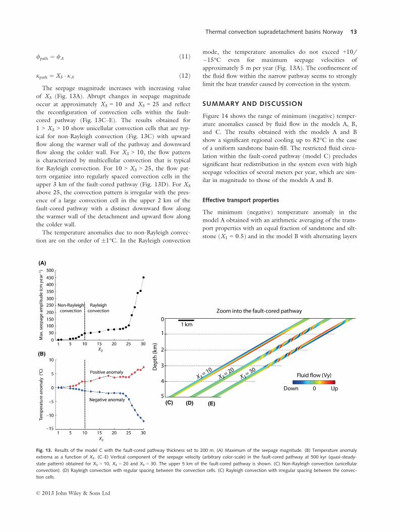
jpath ¼ X3 � jA ð12ÞThe seepage magnitude increases with increasing value
of X3 (Fig. 13A). Abrupt changes in seepage magnitude
occur at approximately X3 = 10 and X3 = 25 and reflect
the reconfiguration of convection cells within the fault-
cored pathway (Fig. 13C–E). The results obtained for
1 > X3 > 10 show unicellular convection cells that are typ-
ical for non-Rayleigh convection (Fig. 13C) with upward
flow along the warmer wall of the pathway and downward
flow along the colder wall. For X3 > 10, the flow pattern
is characterized by multicellular convection that is typical
for Rayleigh convection. For 10 > X3 > 25, the flow pat-
tern organize into regularly spaced convection cells in the
upper 3 km of the fault-cored pathway (Fig. 13D). For X3
above 25, the convection pattern is irregular with the pres-
ence of a large convection cell in the upper 2 km of the
fault-cored pathway with a distinct downward flow along
the warmer wall of the detachment and upward flow along
the colder wall.
The temperature anomalies due to non-Rayleigh convec-
tion are on the order of �1°C. In the Rayleigh convection
mode, the temperature anomalies do not exceed +10/�15°C even for maximum seepage velocities of
approximately 5 m per year (Fig. 13A). The confinement of
the fluid flow within the narrow pathway seems to strongly
limit the heat transfer caused by convection in the system.
SUMMARY AND DISCUSSION
Figure 14 shows the range of minimum (negative) temper-
ature anomalies caused by fluid flow in the models A, B,
and C. The results obtained with the models A and B
show a significant regional cooling up to 82°C in the case
of a uniform sandstone basin-fill. The restricted fluid circu-
lation within the fault-cored pathway (model C) precludes
significant heat redistribution in the system even with high
seepage velocities of several meters per year, which are sim-
ilar in magnitude to those of the models A and B.
Effective transport properties
The minimum (negative) temperature anomaly in the
model A obtained with an arithmetic averaging of the trans-
port properties with an equal fraction of sandstone and silt-
stone (X1 = 0.5) and in the model B with alternating layers
(A)
(B)
(C) (D) (E)
Fig. 13. Results of the model C with the fault-cored pathway thickness set to 200 m. (A) Maximum of the seepage magnitude. (B) Temperature anomaly
extrema as a function of X3. (C–E) Vertical component of the seepage velocity (arbitrary color-scale) in the fault-cored pathway at 500 kyr (quasi-steady-
state pattern) obtained for X3 = 10, X3 = 20 and X3 = 30. The upper 5 km of the fault-cored pathway is shown. (C) Non-Rayleigh convection (unicellular
convection). (D) Rayleigh convection with regular spacing between the convection cells. (C) Rayleigh convection with irregular spacing between the convec-
tion cells.
© 2013 John Wiley & Sons Ltd
Thermal convection supradetachment basins Norway 13

of sandstone and siltstone are, respectively, 62 and 59°C.The arithmetic average of silt- and sandstone permeability
used in the model A corresponds to the transport property
parallel to the bedding of a stratified medium (Dagan
1989) such as the one present in the model B. However,
the component of the effective permeability describing
transport normal to the stratification is given by the har-
monic average, which may be significantly lower than the
arithmetic average. Irrespective of this discrepancy between
the transport properties in the models A and B, the temper-
ature anomaly is almost the same. We speculate that the
presence of the fault-cored pathway in the model B (perme-
ability 10jA) may compensate for a low transport property
normal to the layer stack in the basin. Note that the value
of the effective permeability obtained with geometric aver-
aging corresponds to a random distribution of silt- and
sandstone and lies between the parallel and the normal flow
obtained in a stratified medium (Dagan 1989).
Effect of the sedimentary layering
The occurrence of a significant fluid flow and thermal feed-
back in the case of a layered basin-fill with almost imperme-
able siltstone layers contrasts with previous suggestions that
thermal convection in sedimentary basin is inhibited by the
presence of meter-thick impermeable layers (Bjørlykke et al.
1988). However, we emphasize that, in our simulations,
there is an interconnecting highly permeable pathway at the
base of the basin and that thermally driven flow occurs as a
transient process caused by slanted isotherms during the
exhumation of a crustal-scale detachment footwall. Once
the thermal perturbation associated with exhumation pro-
cesses is relaxed, the thermal convection in the basin ceases
under the regional thermal gradient.
Temperature conditions of the Devonian basins
In the models A and B, the fluid flow affects the thermal
structure of the basin mainly at 3–6 km depth. The fluid
flow is inhibited by the reduced porosity and permeability
below this range, and thermal convection does not operate
efficiently. In the context of the Devonian basins of wes-
tern Norway, which have an estimated burial depth of
about 10 km (Svensen et al. 2001), thermally driven flow
may have not influence the peak temperature conditions of
the sediments. The alteration of ultramafic clasts of the
conglomerates in the Solund basin (Beinlich et al. 2010)
and the pervasive oxidation the Devonian basins of western
Norway may partially result from basin-scale fluid flow dur-
ing the burial of the sediments. However, the temperature
evolution during the formation of the basin cannot be
directly addressed in our models and would require the
consideration of additional effects in the fluid flow budget
such as the compaction of the basin.
Fluid flow in the detachment pathway
The flow and heat transport in the model C is similar to
thermal convection in isolated tilted layers (Bories & Com-
barnous 1973; McKibbin & O’Sullivan 1981; Wood &
Hewett 1982). The onset of Rayleigh convection can be
expected above a critical value of the Rayleigh number
that, in geological systems, varies mostly due to changes in
the permeability, thickness, and temperature gradient
across the layer. In our model, the temperature gradient is
determined by the initial background temperature. The
onset of Rayleigh convection occurs for a pathway perme-
ability of 10jA and a layer thickness of 200 m. As perme-
ability contributes in the same proportion as the square of
the thickness to the Rayleigh number, an equivalent Ray-
leigh number would be found setting the permeability to
jA and the layer thickness to approximately 630 m (assum-
ing that the thermal gradient would not change across the
layer). Such thick detachment pathway might be large con-
sidering the geological framework, but would lead to more
significant thermal anomalies in the system due to a larger
drainage area.
The model C suggests that high fluid velocities inside the
detachment shear zone might not necessarily induce large
cooling of the system if the flow is constrained within a nar-
row pathway. The regional cooling occurs only if the fluid
flow infiltrates from extended areas in the hanging wall, as
illustrated by the models A and B. These results agree well
with similar conclusions drawn by Ferguson et al. (2009)
regarding significant depression of isotherms in the hanging
walls of crustal-scale faults due to groundwater flow.
These results can help to understand heat transfer
induced by fluid flow in detachment zones where high
thermal gradients of 140°C/100 m are documented
(Mulch et al. 2006; Gottardi et al. 2011). Our results
show that the cooling of the metamorphic rocks in the
basement can be significant if the fluid flow in the detach-
ment zone drains the supradetachment basin.
Pore fluid composition
The consequences of diagenetic processes are ignored in
our model. The model parameters such as the density, the
Fig. 14. Range of minimum (negative) temperature anomalies in the mod-
els A, B, and C.
© 2013 John Wiley & Sons Ltd
14 A. SOUCHE et al.

viscosity, and the heat capacity of water depend on the
concentration of solutes that dissolve from the surrounding
sedimentary matrix. The studied geological system is domi-
nated by continental siliciclastic sediments highly cemented
by carbonate minerals. The change of density with depth
in sedimentary basin is positive for silicates in solution and
negative for carbonates and these two contributions nearly
cancel out in sandstone formations with carbonate cement
(Bjørlykke et al. 1988). The most significant density varia-
tion of the pore fluid with depth could come from soluble
salts in the basin potentially inhibiting thermal convection
by introducing a negative density gradient with depth.
However, salt deposits are not found in our geological set-
ting. The fluid-inclusion analysis from metamorphic veins
in the deepest part of the Devonian basins of western Nor-
way (Svensen et al. 2001) documents salinity close to
modern seawater. However, the metamorphic veins formed
in the deepest part of the basin at about 10 km when the
sediments were compacted and the origin of the salinity
could come from metamorphic processes (Svensen et al.
2001). From our modeling, we know that the circulation
of meteoritic water did not reach such depth and we
assume that the metamorphic fluid found in the veins may
have been decoupled from the meteoritic water circulation
in shallower part of the basin. Thus, using pure water as a
pore fluid in our models is a feasible approximation.
2D approach and generalization to 3D
We use the 2D approach to study the flow pattern in the
basin. Different flow configurations can develop in 3D
models of porous convection. The question arises as to
whether such effects would significantly influence the heat
transfer efficiency in the basin. Based on a simplified 3D
model of crustal-scale detachment, Harcou€et-Menou et al.
(2009) studied the flow pattern of thermal convection in
sedimentary basin bounded by a highly permeable shear
zone conduit. Their results show the development of poly-
hedral convection cells (3D structures) within the shear
zone and the transition to convection coils (quasi-2D struc-
tures) in the basin parallel to the shear zone direction. Gar-
ven et al. (2001) investigated the underground temperature
distribution along the hydrothermal system of the Borax
Lake fault in the USA. From their study, the warmer tem-
peratures at depth correspond to circular thermal anomalies
within the fault system and suggest an upwelling of hot flu-
ids in a chimney-like conduit. These papers clearly illustrate
the complexity that we can expect in the case of convective
flow patterns in natural systems. However, the scaling
between the Nusselt (dimensionless number describing the
heat transfer efficiency) and Rayleigh number should remain
similar in the case of 2D and 3D models for low Rayleigh
number values (Combarnous & Bia 1971). Therefore, our
2D model should provide a reliable estimate of the heat
transfer budget for sedimentary basins, which are character-
ized by low values of the Rayleigh number.
CONCLUSIONS
We have studied the thermal anomaly induced by thermal
convection in supradetachment basins above an active
crustal-scale detachment zone. The interplay between fluid
flow and heat transfer has been modeled with and without
the presence of sedimentary layers and fluid pathways along
the detachment. Our conclusions are as follows:
(1) Thermal convection can develop as transient process
above crustal-scale detachments and result in a signifi-
cant thermal effect in the supradetachment basins.
(2) From the specific study of the Devonian basins of wes-
tern Norway, our numerical model shows that the fluid
circulation may have reached a depth of about 5 km
and resulted in the cooling of the basin up to approxi-
mately 80°C.(3) The presence of barrier-like siltstone layers does not
inhibit the flow as long as there is interconnectivity of
the permeable layers in the basin. The fluid pathway
along the detachment may play an important role in
draining meteoritic fluid through the basin.
(4) The fluid pathway along the detachment can host a
high velocity fluid flow but cannot induce large tem-
perature anomaly below and above the detachment if
there is no flow from the basin or the hanging wall.
(5) The Devonian basins of western Norway reached a bur-
ial depth where thermal convection is no longer
expected to contribute to the heat transfer. Thus, the
peak temperature estimates for these basins may be
interpreted with conductive heat transfer. However, the
alteration of the sediments may partially results from
large-scale fluid flow during the burial of the basins.
ACKNOWLEDGEMENTS
The Norwegian Science Council provided basic funding
although a ‘Centre of Excellence’ grant to Physics of Geo-
logical Processes (PGP). The Norwegian Academy of Sci-
ence and Letters and Statoil are thanked for the financial
support through the VISTA grant 6255. The authors
would like to thank K. Iyer and L. R€upke for providing
the fluid property tables used in this study. Thanks to S.
Medvedev for discussions and advice during the elabora-
tion of the manuscript.
REFERENCES
Andersen TB (1998) Extensional tectonics in the Caledonides of
southern Norway, an overview. Tectonophysics, 285, 333–51.Andersen TB, Jamtveit B (1990) Uplift of deep crust during
orogenic extensional collapse: a model based on field studies in
© 2013 John Wiley & Sons Ltd
Thermal convection supradetachment basins Norway 15

the Sogn-Sunnfjord Region of western Norway. Tectonics, 9,1097–111.
Andrews JN, Burgess WG, Edmunds WM, Kay RLF, Lee DJ(1982) The thermal springs of bath. Nature, 298, 339–43.
Athy LF (1930) Density, porosity, and compaction of sedimentary
rocks. American Association of Petroleum Geologists Bulletin, 14,1–24.
Bauer O (1998) PROperties of Water and STeam, PROST 4.1.Technische Universitat Hamburg-Harburg, Hamburg.
Beinlich A, Austrheim H, Glodny J, Erambert M, Andersen TB
(2010) CO2 sequestration and extreme Mg depletion inserpentinized peridotite clasts from the Devonian Solund
basin, SW-Norway. Geochimica et Cosmochimica Acta, 74,6935–64.
Bjørlykke K (1999) Principal aspects of compaction and fluid flowin mudstones. Geological Society, London, Special Publications,158, 73–8.
Bjørlykke K, Høeg K (1997) Effects of burial diagenesis onstresses, compaction and fluid flow in sedimentary basins.
Marine and Petroleum Geology, 14, 267–76.Bjørlykke K, Mo A, Palm E (1988) Modelling of thermal
convection in sedimentary basins and its relevance to diageneticreactions. Marine and Petroleum Geology, 5, 338–51.
Bories SA, Combarnous MA (1973) Natural convection in a
sloping porous layer. Journal of Fluid Mechanics, 57, 63–79.Braathen A, Osmundsen PT, Gabrielsen RH (2004) Dynamicdevelopment of fault rocks in a crustal-scale detachment: an
example from western Norway. Tectonics, 23, TC4010.Brumm M, Wang CY, Manga M (2009) Spring temperatures inthe Sagehen Basin, Sierra Nevada, CA: implications for heat
flow and groundwater circulation. Geofluids, 9, 195–207.Bryhni I (1964) Migrating basins on the old red continent.
Nature, 202, 384–5.Clauser C, Huenges E (1995) Thermal conductivity of rocks and
minerals. In: Rock Physics & Phase Relations: A Handbook ofPhysical Constants (ed. Ahrens TJ), Vol. 3, pp. 105–26. AGU,
Washington, D.C.Combarnous MA, Bia P (1971) Combined free and forced
convection in porous media. Society of Petroleum Engineers, 11,399–405.
Dabrowski M, Krotkiewski M, Schmid DW (2008) MILAMIN:
MATLAB-based finite element method solver for large
problems. Geochemistry, Geophysics, Geosystems, 9, Q04030.
Dagan G (1989) Flow and Transport in Porous Formations.Springer, Berlin.
Elder JW (1967) Steady free convection in a porous medium
heated from below. Journal of Fluid Mechanics, 27, 29–48.Fairley JP (2009) Modeling fluid flow in a heterogeneous, fault-controlled hydrothermal system. Geofluids, 9, 153–66.
Ferguson G, Grasby SE, Hindle SR (2009) What do aqueous
geothermometers really tell us? Geofluids, 9, 39–48.Folkestad A, Steel RJ (2001) The alluvial cyclicity in Hornelenbasin (Devonian Western Norway) revisited: a multiparameter
sedimentary analysis and stratigraphic implications. In:
Norwegian Petroleum Society Special Publications (eds Ole JM,Tom D), Vol. 10, pp. 39–50. Elsevier, Amsterdam.
Garven G, Bull SW, Large RR (2001) Hydrothermal fluid flow
models of stratiform ore genesis in the McArthur Basin,
Northern Territory, Australia. Geofluids, 1, 289–311.Geiger S, Roberts S, Matth€ai SK, Zoppou C, Burri A (2004)
Combining finite element and finite volume methods for
efficient multiphase flow simulations in highly heterogeneous
and structurally complex geologic media. Geofluids, 4, 284–99.
Gottardi R, Teyssier C, Mulch A, Vennemann TW, Wells ML
(2011) Preservation of an extreme transient geotherm in the
Raft River detachment shear zone. Geology, 39, 759–62.Gouze P, Coudrain-Ribstein A, Bernard D (1994) Computation
of porosity redistribution resulting from thermal convection in
slanted porous layers. Journal of Geophysical Research, 99, 697–706.
Gupta VP, Joseph DD (1973) Bounds for heat transport in a
porous layer. Journal of Fluid Mechanics, 57, 491–514.Hacker BR, Andersen TB, Root DB, Mehl L, Mattinson JM,
Wooden JL (2003) Exhumation of high-pressure rocks beneaththe Solund Basin, Western Gneiss Region of Norway. Journal ofMetamorphic Geology, 21, 613–29.
Hacker BR, Andersen TB, Johnston S, Kylander-Clark ARC,
Peterman EM, Walsh EO, Young D (2010) High-temperaturedeformation during continental-margin subduction &
exhumation: the ultrahigh-pressure Western Gneiss Region of
Norway. Tectonophysics, 480, 149–71.Hantschel T, Kauerauf AI (2009) Fundamentals of Basin andPetroleum Systems Modeling. Springer-Verlag, Berlin, Heidelberg.
Harcou€et-Menou V, Guillou-Frottier L, Bonneville A, Adler PM,
Mourzenko V (2009) Hydrothermal convection in and aroundmineralized fault zones: insights from two- and three-
dimensional numerical modeling applied to the Ashanti belt,
Ghana. Geofluids, 9, 116–37.Hasterok D, Chapman DS (2011) Heat production andgeotherms for the continental lithosphere. Earth and PlanetaryScience Letters, 307, 59–70.
Hidalgo JJ, Carrera J (2009) Effect of dispersion on the onset ofconvection during CO2 sequestration. Journal of FluidMechanics, 640, 441–52.
Ingebritsen SE, Manning CE (1999) Geological implications of a
permeability-depth curve for the continental crust. Geology, 27,1107–10.
Johnston S, Hacker BR, Ducea MN (2007) Exhumation of
ultrahigh-pressure rocks beneath the Hornelen segment of the
Nordfjord-Sogn Detachment Zone, western Norway. GeologicalSociety of America Bulletin, 119, 1232–48.
Krabbendam M, Dewey JF (1998) Exhumation of UHP rocks by
transtension in the Western Gneiss Region, ScandinavianCaledonides. Geological Society, London, Special Publications,135, 159–81.
Kylander-Clark ARC, Hacker BR, Johnson CM, Beard BL,
Mahlen NJ (2009) Slow subduction of a thick ultrahigh-pressure terrane. Tectonics, 28, TC2003.
Labrousse L, Jolivet L, Andersen TB, Agard P, H�ebert R, Maluski
H, Sch€arer U (2004) Pressure–temperature–time deformation
history of the exhumation of ultra-high pressure rocks in theWestern Gneiss Region, Norway. Geological Society of AmericaSpecial Papers, 380, 155–83.
Lapwood ER (1948) Convection of a fluid in a porous medium.
Mathematical Proceedings of the Cambridge Philosophical Society,44, 508–21.
Levet S, Toutain JP, Munoz M, Berger G, Negrel P,
Jendrzejewski N, Agrinier P, Sortino F (2002) Geochemistry ofthe Bagn�eres-de-Bigorre thermal waters from the North
Pyrenean Zone (France). Geofluids, 2, 25–40.Magri F, Akar T, Gemici U, Pekdeger A (2012) Numerical
investigations of fault-induced seawater circulation in theSeferihisar-Balc�ova Geothermal system, western Turkey.
Hydrogeology Journal, 20, 103–18.Manning CE, Ingebritsen SE (1999) Permeability of the
continental crust: implications of geothermal data andmetamorphic systems. Reviews of Geophysics, 37, 127–50.
© 2013 John Wiley & Sons Ltd
16 A. SOUCHE et al.

Marques FO, Schmid DW, Andersen TB (2007) Applications of
inclusion behaviour models to a major shear zone system: the
Nordfjord-Sogn Detachment Zone in western Norway. Journalof Structural Geology, 29, 1622–31.
McKibbin R, O’Sullivan MJ (1981) Heat transfer in a layered
porous medium heated from below. Journal of Fluid Mechanics,111, 141–73.
Mulch A, Teyssier C, Cosca MA, Vennemann TW (2006)
Thermomechanical analysis of strain localization in a ductile
detachment zone. Journal of Geophysical Research B: Solid Earth,111, B12405.
Nield DA, Bejan A (2006) Convection in Porous Media. Springer,New York.
Nilsen TH, McLaughlin RJ (1985) Comparison of tectonic
framework and depositional patterns of the Hornelen strike-slipbasin of Norway and the Ridge and Little Sulphur Creek strike-
slip basins of California. Society of Economic Paleontologists andMineralogists, Special Publication, 37, 79–103.
Norton MG (1986) Late Caledonide extension in western
Norway: a response to extreme crustal thickening. Tectonics, 5,195–204.
Odling NE, Larsen Ø (2000) Vein architecture in the Devoniansandstones of the Hornelen basin, western Norway, and
implications for the palaeostrain history. Norsk GeologiskTidsskrift, 80, 289–99.
Osmundsen PT, Andersen TB (2001) The middle Devonianbasins of western Norway: sedimentary response to large-scale
transtensional tectonics? Tectonophysics, 332, 51–68.Osmundsen PT, Andersen TB, Markussen S, Svendby AK (1998)Tectonics and sedimentation in the hangingwall of a major
extensional detachment: the Devonian Kvamshesten Basin,
western Norway. Basin Research, 10, 213–34.Osmundsen PT, Bakke B, Svendby AK, Andersen TB (2000)Architecture of the middle Devonian Kvamshesten group,
Western Norway: sedimentary response to deformation above a
ramp-flat extensional fault, 503–35.Palm E, Weber JE, Kvernvold O (1972) On steady convection ina porous medium. Journal of Fluid Mechanics, 54, 153–61.
Pau GSH, Bell JB, Pruess K, Almgren AS, Lijewski MJ, Zhang K
(2010) High-resolution simulation and characterization ofdensity-driven flow in CO2 storage in saline aquifers. Advancesin Water Resources, 33, 443–55.
Person M, Raffensperger JP, Ge S, Garven G (1996) Basin-scale
hydrogeologic modeling. Reviews of Geophysics, 34, 61–87.Rees DAS, Postelnicu A (2001) The onset of convection in an
inclined anisotropic porous layer. International Journal of Heatand Mass Transfer, 44, 4127–38.
Root DB, Hacker BR, Gans PB, Ducea MN, Eide EA,Mosenfelder JL (2005) Discrete ultrahigh-pressure domains in
the Western Gneiss Region, Norway: implications for formation
and exhumation. Journal of Metamorphic Geology, 23, 45–61.Sclater JG, Christie PAF (1980) Continental stretching: anexplanation of the post-Mid-Cretaceous subsidence of the
Central North Sea Basin. Journal of Geophysical Research, 85,3711–39.
Seguret M, Seranne M, Chauvet A, Brunel M (1989) Collapse
basin: a new type of extensional sedimentary basin from the
Devonian of Norway. Geology, 17, 127–30.
Seranne M, Seguret M (1987) The Devonian basins of westernNorway: tectonics and kinematics of an extending crust. Journalof the Geological Society, London, Special Publications, 28,537–48.
Shalev E, Lyakhovsky V, Yechieli Y (2007) Is advective heat
transport significant at the Dead Sea basin? Geofluids, 7, 292–300.
Shewchuk J (1996) Triangle: engineering a 2D quality mesh
generator and Delaunay triangulator. In: Applied ComputationalGeometry Towards Geometric Engineering (eds Lin M, Manocha
D), Vol. 1148, pp. 203–22. Springer, Berlin – Heidelberg.Shewchuk JR (2002) Delaunay refinement algorithms for triangular
mesh generation. Computational Geometry, 22, 21–74.Simms MA, Garven G (2004) Thermal convection in faulted
extensional sedimentary basins: theoretical results from finite-element modeling. Geofluids, 4, 109–30.
Souche A, Beyssac O, Andersen TB (2012a) Thermal structure of
supra-detachment basins: a case study of the Devonian basins of
western Norway. Journal of the Geological Society, London, 10,213–34.
Souche A, Medvedev S, Andersen TB, Dabrowski M (2012b)
Shear heating in extensional detachments: implications for thethermal history of the Devonian basins of western Norway. Part
of Alban Souche’s PhD thesis, Series of dissertations submitted
to the Faculty of Mathematics and Natural Sciences, University
of Oslo, No. 1254, ISSN 1501-7710.Steel RJ, Næhle S, Nilsen H, Røe SL, Spinnangr A (1977)
Coarsening-upward cycles in the alluvium of Hornelen Basin
(Devonian) Norway: sedimentary response to tectonic events.
Geological Society of America Bulletin, 88, 1124–34.Straus JM (1974) Large amplitude convection in porous media.
Journal of Fluid Mechanics, 64, 51–63.Svensen H, Jamtveit B, Banks DA, Karlsen D (2001) Fluids andhalogens at the diagenetic–metamorphic boundary: evidence from
veins in continental basins, western Norway. Geofluids, 1, 53–70.Torsvik TH, Sturt BA, Swensson E, Andersen TB, Dewey JF
(1992) Palaeomagnetic dating of fault rocks: evidence forPermian and Mesozoic movements and brittle deformation
along the extensional Dalsfjord Fault, western Norway.
Geophysical Journal International, 109, 565–80.Trew M, McKibbin R (1994) Convection in anisotropic inclinedporous layers. Transport in Porous Media, 17, 271–83.
Ungerer P, Burrus J, Doligez B, Chenet PY, Bessis F (1990)
Basin evaluation by integrated two-dimensional modeling ofheat transfer, fluid flow, hydrocarbon generation, and migration.
American Association of Petroleum Geologists Bulletin, 74, 309–35.
Wangen M (1994) Numerical simulation of thermal convection incompacting sedimentary basins. Geophysical JournalInternational, 119, 129–50.
Wangen M (1997) Non-Rayleigh convection caused by
ground surface topography. Transport in Porous Media, 26,299–318.
Wood JR, Hewett TA (1982) Fluid convection and mass transfer
in porous sandstones – a theoretical model. Geochimica etCosmochimica Acta, 46, 1707–13.
Wooding RA (1957) Steady state free thermal convection of liquid
in a saturated permeable medium. Journal of Fluid Mechanics, 2,273–85.
Yang J, Large RR, Bull SW (2004) Factors controlling free thermal
convection in faults in sedimentary basins: implications for the
formation of zinc–lead mineral deposits. Geofluids, 4, 237–47.Young DJ, Hacker BR, Andersen TB, Gans PB (2011) Structureand 40Ar/39Ar thermochronology of an ultrahigh-pressure
transition in western Norway. Journal of the Geological Society,168, 887–98.
© 2013 John Wiley & Sons Ltd
Thermal convection supradetachment basins Norway 17