modeling slip gradients and internal stresses in crystalline microstructures … · modeling slip...
TRANSCRIPT
MODELINGSLIPGRADIENTSANDINTERNALSTRESSESINCRYSTALLINEMICROSTRUCTURES
WITHDISTRIBUTEDDEFECTS
RAMINAGHABABAEI
B.S.(Hons.),UNIVERSITYOFTEHRAN,2006
ATHESISSUBMITTED
FORTHEDEGREEOFDOCTOROFPHILOSOPHY
DEPARTMENTOFMECHANICALENGINEERING
NATIONALUNIVERSITYOFSINGAPORE
2011

I
DEDICATION
Tomydearparents
MitraandAmir
whohavesupportedandencouragedmefrombirth
Tomybelovedwife
Marjan
whohasofferedmeunconditionalloveandhappiness

II
ACKNOWLEDGEMENTS
This dissertation would not have been possible without the guidance and the
support of several individuals who helped me with their valuable assistance in the
preparationandcompletionofthisstudy.
First and foremost,I would like expressmy deep gratitude tomy supervisor Dr.
Shailendra P. Joshi for his sound advice and careful guidance during my Ph.D. The
innumerable discussions I had with him provided me a good understanding of the
mechanicsandphysicstogether.Withouthissupport,thisworkwouldneverhavebeen
accomplished.
IwouldliketowarmlythankProfessorJ.N.Reddyforhissupportandintroducing
me to the field of nonlocal theories. His profound understanding of the continuum
mechanicsandfiniteelementtheorieshelpedmealotincompletingthiswork.
Inaddition,IwouldliketothankProfessorR.NarasimhanfromtheIndianinstitute
ofScience for fruitfuldiscussions Ihadwithhim.Amongmypeers, Igreatlyvalue the
friendship IsharewithHamidrezaMirkhani. Iappreciate thehelpheextendedduring
myPhDandmanyusefuldiscussionswehadonthetopicsinmechanicsofmaterials.I
also thank my friends and colleagues Dr. Jing Zhang and A.S. Abhilash for their
commentsandsuggestionsaboutmyworks.Ialsogratefullyacknowledgetheresearch
scholarshipprovidedtomebyNationalUniversityofSingapore.
IowemyspecialthankstomylovelywifeMarjanwhohaschosentospendherlife
with me as my soul mate. Finally, this undertaking could never have been achieved
without the encouragement of my wonderful father, mother and sister who have
supportedmefrombirth.

III
TABLE OF CONTENTS
DEDICATION....................................................................................................................................I
ACKNOWLEDGEMENTS................................................................................................................II
TABLEOFCONTENTS.................................................................................................................III
SUMMARY.......................................................................................................................................VI
LISTOFTABLES..........................................................................................................................VII
LISTOFFIGURES........................................................................................................................VIII
LISTOFSYMBOLS.......................................................................................................................XII
1 INTRODUCTION....................................................................................................................1
1.1 Length‐scaleeffectsinresponseofmaterials..................................................1
1.2 Length‐scaleEffectsinCrystallineMicrostructures......................................3
1.2.1 PlasticDeformationatDifferentLength‐scales........................................4
1.2.2 ABriefOverviewofExperimentalObservationsofLength‐scaleEffectsinPlasticity:............................................................................................10
1.2.3 ContinuumdescriptionsofDislocation‐mediatedCrystalPlasticity....................................................................................................................................13
1.2.3.1 Classicalcrystalplasticity.............................................................................13
1.2.3.2 ContinuumcrystalplasticitywithGNDs................................................15
1.3 ScopeandObjectivesoftheThesis....................................................................18
2 AMechanism‐BasedGradientCrystalPlasticityInvestigationofMetalMatrixComposites.................................................................................................................20
2.1 Introduction.................................................................................................................20
2.2 ComputationalImplementationofMSGCPTheory.....................................24
2.2.1 Slipgradientcalculation..................................................................................27
2.2.2 Timeintegrationscheme.................................................................................28
2.3 Length‐scaledependentMMCresponseinducedbythermalresidualstresses...........................................................................................................................29
2.3.1 Computationalresultsforsinglecrystalswithinclusions................32
2.3.2 CrystalorientationandinclusionsizeeffectsonthermalGNDdensitydistribution...........................................................................................34

IV
2.3.3 Size‐dependentstress‐strainresponsewithpre‐existingthermalGNDdensity..........................................................................................................43
2.3.4 Inclusionshapeeffectonstress‐strainresponsesinthepresenceofthermalGNDdensity.........................................................................................47
2.3.5 ThermalGNDdensitydistributioninpolycrystallineMMCunderthermalloading...................................................................................................52
2.4 Grainsize‐inclusionsizesinteractioninMMCatmoderatestrainusingMSGCP.............................................................................................................................54
2.4.1 ModelMicrostructures.....................................................................................58
2.4.2 Length‐scaledependentpolycrystallineresponse..............................61
2.4.3 Length‐scaleDependentMMCResponse.................................................63
2.4.4 Grainorientationandmeshsizeeffects...................................................64
2.4.5 Grainsize‐inclusionSizeInteractionstrengthening...........................66
2.4.6 AnalyticalModelforInteractionStrengthening....................................70
2.5 SummaryandOutlook.............................................................................................75
3 Length‐scaleDependentContinuumCrystalPlasticitywithInternalStresses.......................................................................................................................................77
3.1 Introduction.................................................................................................................77
3.2 Background..................................................................................................................80
3.3 KinematicsofCompatibleandIncompatibleDeformations...................84
3.3.1 CompatibilityofLatticeCurvature:............................................................85
3.3.2 RelationbetweenIncompatibleElasticStrainTensorandtheGNDDensityTensor:...................................................................................................87
3.4 InternalStressTensor:StressFunctionApproach.....................................88
3.4.1 InternalStressunderPlaneStrainCondition:IsotropicElasticity92
3.4.2 InternalStresswithElasticAnisotropy....................................................95
3.5 ThermodynamicallyConsistentVisco‐plasticConstitutiveLaw...........96
3.5.1 Firstlawofthermodynamics:PowerBalance.......................................97
3.5.2 Secondlawofthermodynamics:Powerimbalance.............................98
3.6 ResultsandDiscussion..........................................................................................101
3.6.1 TaperedSingleCrystalSpecimenSubjectedtoUniaxialLoading101
3.6.2 SingleCrystalLamellaSubjectedtoSimpleShear.............................110
3.7 Summary......................................................................................................................115
4 ACrystalPlasticityAnalysisofLength‐scaleDependentInternalStresseswithImageEffects..........................................................................................................117
4.1 Introduction...............................................................................................................117

V
4.2 NonlocalContinuumTheorywithInternalStressandImageFields120
4.3 SingleCrystalSpecimenunderPlane‐StrainPureBending:RoleofFreeSurfaces........................................................................................................................125
4.4 Length‐scaleDependentPureBendingResponseofSingleCrystals139
4.4.1 Monotonicresponse........................................................................................143
4.4.2 ComparisonwithExperiment.....................................................................146
4.4.3 Length‐scaleDependentBauschingerEffect........................................155
4.5 SummaryandOutlook...........................................................................................161
5 SummaryandRecommendations..............................................................................163
5.1 Summary......................................................................................................................163
5.2 Recommendationsforfuturework..................................................................166
6 ListofPublication...........................................................................................................169
7 Bibliography.....................................................................................................................170
AppendixA. ANoteonContinuumDescriptionsofGNDDensityTensor...........189
AppendixB. Kernelfunctions...........................................................................................194
AppendixC. Numericalintegrationconvergencestudy...........................................200

VI
SUMMARY
This thesis addresses a formulation, computational implementation and
investigation of length‐scale effects in the presence of heterogeneities and internal
stresses in continuum crystal plasticity (CCP). First, we implement a gradient crystal
plasticity theory in a finite element framework. Using this, we investigate the crystal
orientation‐dependent size effects due to thermal stresses on the overall mechanical
behavior of composites. Then, through systematic simulations, we demonstrate
additionalHall‐Petch typecoupling resulting from inclusion size‐grain size interaction
and propose an analytical model for the same. Since the continuum crystal plasticity
augmentedbyshortrange interactionofdislocations fails topredict length‐dependent
strengtheningatyieldingpoint,athree‐dimensionalconstitutivetheoryaccounting for
length‐scale dependent internal residual stresses is developed. The second‐order
internalstresstensorisderivedusingtheBeltramistressfunctiontensorthatisrelated
to the Nye dislocation density tensor. One of the common sources of these internal
residual stresses is the presence of ensembles of excess (GN) dislocations which
sometimesreferredtoasamesoscopiccontinuumscale.Theresultinginternalstressis
discussedintermsofthelong‐rangedislocation‐dislocationanddislocation‐boundaries
elastic interactions and physical and mathematical origins of corresponding length
scales are argued. Itwill show that internal stress is a function of spatial variation of
GND density in absence of finite boundarieswhere internal stress arises fromGND –
GND long rangeelastic interactions.However inpresenceof finiteboundaries suchas
free surfaces or interfaces, additional source of internal stress is present due to long
rangeinteractionbetweenGNDandboundaries.Usingtheseapproaches,weinvestigate
several important examples thatmimic real problemswhere internal stressesplay an
importantroleinmediatingtheoverallresponseundermonotonicandcyclicloading.

VII
LIST OF TABLES
Tables Page
Table 2‐2.Activatedslipsystemsfortwolimitingcrystalorientations..................................37
Table 2‐3.MicrostructuralsizecombinationsforMMCsimulations........................................66
Table 2‐4.MicrostructuralsizecombinationsforMMCsimulations........................................74
Table 3‐1.Summaryofgoverningequations.....................................................................................100
Table 3‐2.Summaryofconstitutiveequations.................................................................................101
Table 3‐3.Summaryofunknownvariablesandavailableequations....................................101
Table 4‐1.Parametersusedintheanalyticalmodelforinternalstressandpredictionofbeambehaviorresponse.......................................................................................................143
Table 4‐2.LocalandglobalcoordinatesofactiveslipsystemaccordingtoMotzetal.,(2005)singlecrystalbendingexperiment...................................................................147
VIII
LIST OF FIGURES
Figures Page
Figure 1.1. Plastic deformation and appropriate unit processes for modeling atdifferentscales.......................................................................................................................................................7
Figure 1.2.Dislocationinteractionsatdifferentlength‐scales..............................................9
Figure 1.3. Schematic of geometrically necessary dislocations (GNDs) pile up atgrainboundaryinordertoaccommodatecompatibleplasticdeformation...........................11
Figure 1.4.FormationofGNDinpresenceofstraingradientin(a)bendingofsinglecrystal (b) nano/micro indentation (c) metal matrix composite contains nano/microinclusions...............................................................................................................................................................12
Figure 2.1.Kinematicsofsinglecrystaldeformation...............................................................24
Figure 2.2.(a)AnEight‐nodeplanestrainFEwithfourGPsand(b)alinearpseudo‐element constructed from the GPs of the actual FE where and are the localisoparametric coordinates. The slip and normal directions and of a typical slipsystem arealsoshown(b).........................................................................................................................27
Figure 2.3.Metalmatrixcomposite(MMC)withuniformarrangementofinclusionsandunitcellcomprisingsinglecrystalmatrixandsquareinclusion.........................................33
Figure 2.4. Crystal orientation and inclusion size dependent distribution ofeffectiveGNDdensity |Δ | 500, 1 ........................................................................35
Figure 2.5.(a)DistributionofeffectiveGNDdensity alongthediagonallineasshown in embedded figure. |Δ | 500 (b) evolution of average GND density duringcoolingprocess( 1 ..........................................................................................................36
Figure 2.6. Distribution of normal stress under thermal loading for differentcrystalorientationofmatrix( 1 )...............................................................................................38
Figure 2.7.(a)EffectiveGNDdensity distributionfordifferentinclusionsizes,(b) average thermal GND density evolution during thermal cooling for differentinclusion sizes, (c) Inverse relationof average thermalGNDdensity and inclusionsize |Δ | 500, 45 ...........................................................................................................................41
Figure 2.8. Contributions of individual mismatch components under thermalloading( 1 ..........................................................................................................................................42
Figure 2.9. True stress‐true strain response for MMC models under thermomechanicalloading.BulkbehaviorispredictedbyCCPwhilesizedependentbehaviorismodeledusingMSGCPforinclusionsize 1 , 45°.......................................................44
Figure 2.10. Influence of the prior thermal loading on (a) true stress‐true strainresponse and (b) hardening rate. ( 1 , 45°), obtained from MSGCPcalculations............................................................................................................................................................45

IX
Figure 2.11.AverageGNDdensityevolutionunderconsequentthermal‐mechanicalloading.( 1 , 45°)......................................................................................................................47
Figure 2.12. Distribution of thermal GND density around square and circularinclusionsembeddedinsinglecrystalwith(a) 0°and(b) 45°..................................48
Figure 2.13. True stress‐true strain response for MMC models comprising twodifferentinclusionshapes. 0°.............................................................................................................49
Figure 2.14.InfluenceofinclusionshapeonthermalresidualstressesinMMCbasedon(a)CCPand(b)MSGCP. 0° ..........................................................................................................51
Figure 2.15.Schematic indicatingan interactionbetween inclusionshapeandsizeeffectsatthelocationsofstressconcentrations..................................................................................51
Figure 2.16.EffectiveGNDdensitydistributioninpolycrystallineMMCwithrandomgrain orientation for different grain size (a) 0.5μm and (b) 0.25μm.
1 , |Δ | 500 ...............................................................................................................................53
Figure 2.17. Average GND density distribution evolution in single crystalline andpolycrystallineMMC.........................................................................................................................................54
Figure 2.18. MMC with micron‐sized inclusions embedded in a nanocrystallinematrix(JoshiandRamesh,2007)...............................................................................................................55
Figure 2.19.Representativemodelsfor(a,c)polyXand(b,d)MMCarchitectures..59
Figure 2.20.Truestress‐truestrainresponsesforpolyXmodelswithdifferentgrainsizes...........................................................................................................................................................................62
Figure 2.21.Normalizedgrainsizedependentflowstressat 2%forpolyXwithidenticalgrainorientations.TheplotalsoincludestheempiricalHall‐Petch . andinversegrainsize fits..........................................................................................................................62
Figure 2.22. Grain‐size dependent true stress‐true strain curves for MMC (solidlines) with 2 . The corresponding polyX responses (Figure 2.20) are alsoincludedforcomparison.................................................................................................................................64
Figure 2.23. Standard deviation in Δ arising for a given computationalmodelwithfixed butdifferentrealizationsofgrainorientations.Asexpected,thevariationissmallerforfiner ............................................................................................................................................65
Figure 2.24.Meshconvergenceforthestress‐straincurvesofMMC 2 ,1 withdifferentmeshsizes .................................................................................................................65
Figure 2.25.Flowstress 2%normalizedbybulkpolyXyieldstressvariationofMMCsasafunctionofgrainsize............................................................................................................67
Figure 2.26.Inclusionsizeeffectonthenormalizedflowstress(normalizedbybulkpolyXyieldstress)forlargegrainsizes, 3 (negligiblegrainsizeeffect)..................68
Figure 2.27. Distribution of the effective GND density / along path a‐b 2 fordifferentgrainsizes.........................................................................................................69

X
Figure 2.28.Schematicofaninclusionembeddedinapolycrystallinemassoffinergrains........................................................................................................................................................................71
Figure 2.29.Variationoftheinteractionstrengtheningwiththeproduct ....74
Figure 3.1. Examples illustrating the contributions of GND density to enhancedhardeningin(a)purebeambending‐dissipativehardening,(b)non‐uniformbending‐dissipativeandenergetichardening.........................................................................................................82
Figure 3.2.Schematicillustratingthenon‐localityarisingfromthepresenceofGNDdensityatacontinuumpointandthedistributionoftheGNDdensityaroundthatpoint......................................................................................................................................................................................83
Figure 3.3. Variation of a typical component of the third gradient of the GreenfunctioninEq( 3.31).........................................................................................................................................91
Figure 3.4.Ataperedbarunderuniaxialloading.Dashedtaperededgesindicatethattheyaresufficientlyawayfromthecenterlineofthespecimen...............................................102
Figure 3.5.Plastic slip alongbaraxisy forvarious ratioof / for taperedspecimenundermonotonictension.......................................................................................................105
Figure 3.6.Resolvedshearstressversusplasticslipat fortaperedbarundermonotonictensionforvariousratios(a) / ,and(b) / ....................................106
Figure 3.7.Distributionofnormalizedinternalshearstress ∗/ alongthetaperedspecimenundermonotonictensionfor(a) 2.86°,(b) 5.71°. 50....................107
Figure 3.8.Resolvedshearstressversusplasticslipat fortaperedbarundercyclicloading(a) 100,(b) 50...................................................................................................108
Figure 3.9.Resolvedshearstressversusplasticslipaty=Lforvarioustaperedangleundercyclicloading( =100)(a) 2.86°,(b) 5.71°..........................................................109
Figure 3.10.Asinglelamellawithinanano‐twinnedcrystalundersimpleshear..110
Figure 3.11.(a)Normalizedresolvedshearstress / versusaverageplasticslipasafunctionof for 90°,(b)Normalizedresolvedshearstress / versusnormalizedlamellathicknessat 0.2%..................................................................................................................112
Figure 3.12.(a)Distributionofplasticslip onaslipsystemasafunctionof for90° versus distance normalized by lamella thickness (b) Normalized internal
resolvedshearstress ∗/ alongthelamellathicknessasafunctionof for 90°,and(c)Normalizedinternalresolvedshearstress ∗/ versusnormalizedlamellathickness...................................................................................................................................................................................114
Figure 4.1.Decompositionof the internalstressproblemforaspecimenhostingageneralGNDdensitydistribution.Seetextfordiscussion...........................................................123
Figure 4.2. Schematic showing effective GND arrangement in a specimen underuniformcurvature.Thespecimenthickness is 2 andtheGNDdensity isdescribedbytheglobal , andlocal , coordinates........................................................................................126
Figure 4.3. Internal stress components variation across thickness for 0.25 ..............................................................................................................................................................128

XI
Figure 4.4. Variation of normalized internal stress along the normalizedspecimenthickness fordifferentvaluesofnormalizedinternallength‐scale ............129
Figure 4.5.Variationofnon‐dimensionalstressesin direction( and )overbeamthicknessforagivennormalized internal length‐scale 10 (Eq.4.8a,b).Notethatthecomponentsareequalandoppositeresultinginoverall ∗ 0...........................132
Figure 4.6.Variationof withYandL.(SeeEq.4.10a)..................................................133
Figure 4.7.Variationof respectto(a)YatL=10and(b)LatY=1.(SeeEq.4.10b)..................................................................................................................................................................................134
Figure 4.8. Variation of the normalized total internal stress with normalizedinternallength‐scale atspecimensurface( 1)......................................................................135
Figure 4.9. a) Normalized stress variation across normalized specimen thickness/ at 0.05,b)Stress‐straincurvesatspecimensurfaces 1 fordifferent
valuesof / ............................................................................................................................................145
Figure 4.10.ContributionofshortrangeGNDinteractionversus / andlongrangeGNDinteractionsversus. / onflowstressat5%surfacestrain..........................................146
Figure 4.11. Schematic of single crystal specimen under pure bending, crystalorientationandcorrespondingactiveslipsystems........................................................................148
Figure 4.12.Comparisonoftheanalyticalresults(Eq.4.17)fordifferentvaluesof withtheexperimentalresultsofMotz,etal(2005)........................................................................150
Figure 4.13.TypicalGNDarrangementindoublesymmetricslipdeformationunderpurebending......................................................................................................................................................152
Figure 4.14. Bending‐straightening cyclic response of single crystalline specimenorientedfordoublesymmetricslip........................................................................................................156
Figure 4.15.Overall stress variation across specimen thickness at different strainshowninfigure4.14.......................................................................................................................................158
Figure 4.16. Length‐scale dependent dissipative (isotropic) and energetic(kinematic) hardening components of pure bending responses for two differentspecimenthickness.........................................................................................................................................159
XII
LIST OF SYMBOLS
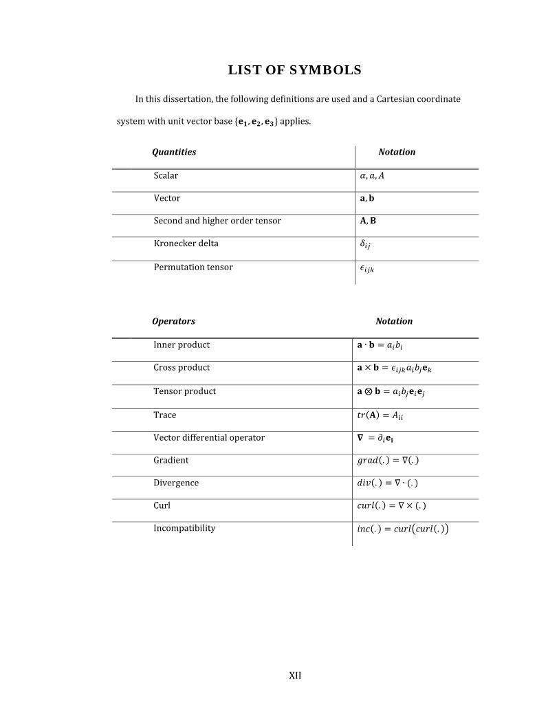
Inthisdissertation,thefollowingdefinitionsareusedandaCartesiancoordinate
systemwithunitvectorbase , , applies.
Quantities Notation
Scalar , ,
Vector ,
Secondandhigherordertensor ,
Kroneckerdelta
Permutationtensor
Operators Notation
Innerproduct ∙
Crossproduct
Tensorproduct ⨂
Trace
Vectordifferentialoperator
Gradient . .
Divergence . ∙ .
Curl . .
Incompatibility . .

XIII
Nomenclature Notation
Deformationgradient
Displacementgradient
Velocitygradient
Compatible/Incompatiblestrain ,
Latticecurvature
Rotationvector
Spintensor
Incompatibilitytensor
GNDdensitytensor A
Slipdirectionof slipsystem
Normaldirection
EffectiveGNDdensity
Plasticslip
Plasticsliprate
Referenceplasticslip
Appliedstresstensor
Internalstresstensor ∗
Internalstressduetodislocation‐dislocation
interaction
Internalstressduetodislocation‐boundary
interaction(Imagestress)
Appliedresolvedshearstress
Internalresolvedshearstress ∗
Beltramistressfunctiontensor
Slipresistance
Hardeningmodulus
Elasticmodulus/Compliancetensor ,
Displacement
Bodyforce
Tractionforce

1
1 INTRODUCTION
1.1 Length-scale effects in response of materials
Nature relies on engineering its creations in a hierarchical manner in order to
impartimpressivepropertiesforarangeofapplications(Endy,2005;Fratzl,2007;Gao
et al., 2003). Intriguing examples of natural structural systems such as spider’s silk
(Vollrath, 2000) and nacre in abalone shells (Meyers, 2008) indicate impressive
strengthsresultingfromstrong,hierarchicalarchitecturesatsmalllength‐scalescoupled
with robust failure resistance mechanisms. Our singular quest to mimic nature has
spawnedtremendousexcitementinsynthesizingmaterialsandconstructingstructures
that are aimed at using some of the natural principles. The notion of the statement
SmallerisStrongerhasfar‐reachingimplicationsinengineeringthematerialsthatpush
thelimitsofstructuralperformance.
Length‐scaleeffectsonmaterialproperties,oftentermedassizeeffects,areofgreat
importanceincurrentengineeringandscientificapplicationsthatrangefromlarge‐scale
structures that demand high strength at lower weight (e.g. automotive, aerospace
systems) to miniaturized micro and nano‐scaled systems that are being adopted in
biomedicalandelectronicsapplications. Incrystallinemetals, size‐effects are reported
in a varietyofmaterial properties including elasticity (Agrawal et al., 2008;Wuet al.,
2005),plasticity(Dehm,2009;GreerandHosson,2011),thermal(Rohetal.,2010)and
electrical conductivities (Boukai et al., 2008), as specimen dimensions and/ or
microstructuralfeatures(e.g.diameterinnanowire,grainsizeincrystallinemetals)are
reduced. An understanding of these effects is especially important as our ability to
designandmanufacturestructuresatminiaturized length‐scalesandwithnano‐scaled

2
internal structures continues to acquire higher levels of sophistication (Zhu and Li,
2010).
Inmetallic microstructures, a general trend reported in artificial systems is that
microstructures with smaller features exhibit stronger behaviors than those with
coarser features (Greer and Hosson, 2011). For example, the yield strength of
nanocrystallinepurealuminumwithanaveragegrainsizeof40nmisnearly10times
morethanthatofacoarse‐grainedpurealuminum(Gianolaetal.,2006).Nanotwinned
copperwithtwinthicknessof~35nmisnearly7timesstrongerthancoarse‐grained
purecopper(Luetal.,2009).Forafixedinclusionvolumefractiontheyieldstrengthofa
metal matrix composite (MMC) increases dramatically with decreasing inclusion size
(Lloyd, 1994). Myriad examples pertaining to thin films (Haque and Saif, 2003),
miniaturizedbeams(Motzetal.,2005),pillars(GreerandNix,2006),rods(Wongetal.,
1997)unequivocallyendorsethesmallerisstrongerphenomenon.Inotherwords,with
all other propertiesheld constant, the smaller the geometrical ormicrostructural size
the stronger a material is expected to be. Seen slightly differently, these examples
suggest that theelasticandplasticpropertiesofmaterials cease tobepurelymaterial
parameters as the specimen dimensions or microstructural features approach
characteristic microstructural length‐scale (Greer and Hosson, 2011). All of these
observations have a commonmessage: smaller is stronger. In a broad sense, the size‐
dependentbehaviorsofmicroandnano‐scaledstructuresareassociatedwiththehigh
surface (or interface) area to volume ratio. This is in‐turn based on the idea that the
atomic interactions at boundaries tend to be different from those in the bulk of a
material.
Rapid increase in computational power in the recent decades has enabled
performing computational simulations that supplement, or at times enable,
experimental investigations into the physics andmechanics at small length‐scales. An

3
importantquestionthatarisesisthatofthechoiceofspatialandtemporalresolutions.
Atomistic provide a virtual experimental paradigm to capture the prevailing
mechanismsatveryhighspatio‐temporalresolution,butmaybecomecomputationally
prohibitive at larger structural length‐scale (even beyond a few hundred nm). At the
otherextreme,continuummechanicsprovidesastrongtheoreticalconstructthatcanbe
extremelyuseful ifappropriatelyendowedwithanabilitytopredictsize‐effects,albeit
atthelossofsub‐scaledetails.Athirdpossibilityisjudiciouslycombiningtheatomistics
andcontinuummechanicstoprovideaconcurrentmulti‐scalemodelingapproach.The
choiceofanapproachisdictatedbythedetailsweareinterestedinandthescalesthat
needtobebridgedwiththeavailablecomputationalpower.
Inthiswork,ourfocusisonasmallsubsetwithinthevastexpanseoflength‐scale
dependent behaviors.Weare interested in some of the size‐effects thatprevail in the
mechanicalbehaviorofcrystallinemetals.Aparticularcategoryofsize‐effectscovered
in this thesis pertains to crystalline plasticity that arises from interacting effects
betweendislocationsandtheirambience.Forexample,dislocationsgetstoppedbyhard
boundariesandgetannihilatedbyfreesurfaces.Inanotherscenario,dislocationstalkto
other dislocations in their neighborhood. All these events result in length‐scale
dependentmacroscopicplasticresponsesthatmanifestasstrengtheningofamaterial.
Weprobesomeoftheseeffectsinheterogeneouscrystallinemicrostructuresofcurrent
interestthroughanalyticalandcomputationalapproaches.
Tosetthestagefortherestofthethesis,webrieflydiscussdislocationplasticityin
crystallinemetalsasitcanbedescribedatvariouslength‐scales.
1.2 Length-scale Effects in Crystalline Microstructures
During the last couple of decades, crystalline metallic materials especially Face‐
Centered‐Cubic(FCC)metalsarevastlyusedasthenano/microstructuresfornumerous

4
applications.Therefore,itiscriticallyimportanttoobtainfundamentalinsightintotheir
length‐scaledependentmechanicalbehavioratmicroandnanoscales.Theexperimental
andtheoreticalaspectsof these length‐scaledependentbehaviorsarediscussedinthe
followingsections.
1.2.1 Plastic Deformation at Different Length-scales
In crystallinematerials, the unit processes that are deemed relevant to describe
plasticity must be identified based on the length and time‐scales of interest. From a
thermodynamicviewpoint,movementofthedislocationsduringplasticdeformation is
mediatedbycrystal latticeresistance.Thiscrystal latticeresistancecanorneedstobe
defined at different scales. At the finest length‐scale (atomistic), it is an inherently
dynamicalprocessof atomicmotions. In thedevelopmentof an incrementally coarse‐
grainedapproach,someofthemicrostructuraldetailsatthefinerscalearesmearedout
bymakingcertainassumptionswithregardsthelength‐andtime‐scalesatthesub‐scale
vis‐à‐visthecurrentscalesofinterest.Thisoftenprovidesamotivationtodefineamore
relevant unit process at the coarser length‐scale by coarsening the sub‐scale defect
dynamics.ThereviewarticlebyZaiserandSeeger(2002)servesasausefulreference.A
possiblecascadingflowofsuchamulti‐scalingprocess(Fig.1.1)thatisdeemeduseful
forthisthesisisbrieflydiscussedhere:
Atomicscale–describestheindividualatomintermsofitsfinercomponentssuch
aselectrons.Density functionaltheory(DFT)isthemostpopularmethodtoinvestigate
the total ground‐level energy and properties of a system of interacting electrons in
particular atomsandmolecules (Sholl andSteckel, 2009). Ituses the functionalof the
electrondensity,whichprovidesthepotentialfunctionasabasisformoleculardynamic
simulations.

5
Nanoscopicscale–Atthisscale, the individualatomsandmoleculesareresolved
where the information from the atomic scale that is coarse‐grained is the interatomic
interaction.Moleculardynamics(MD)isapowerfultooltocomputationallysimulatethe
physicalmotionsofatomsandmoleculesunderexternalstimuli.InMDsimulations,the
Newton’s equations of motion for a system of interacting particles are numerically
solvedwhereintermolecularinteractionsaredescribedbyapotentialfunctionprovided
by theatomic scale.A reasonably largeensembleof atoms ismodeled, and theelastic
andplasticpropertiesemergenaturallythroughinteratomicinteractions.Atthisscale,
the unit process that describes plastic deformation is the nucleation andmobility of
individual dislocations within a crystalline lattice. Given the inherent dynamics of
atomicmotions, typicalMDcalculationsneedhigh temporal resolution in theorderof
femto to pico seconds. The interactive long‐ and short‐range interactions between
dislocations arenaturally resolvedat this scale andprovide the essential physics that
can be rationalized as constitutive descriptions at coarser scales. Nanoscopic lattice
resistanceisreferredtoasthePeierlsstress.Itdependsstronglyonthestrainrateand
canbethermallyactivated;hence,itisreferredtoasthethermallatticeresistance.
Microscopic scale – At this length‐scale, the atomistic resolution is smeared out
renderinganelasticcontinuum,butthediscretenessofdislocationsisretained.Theyare
modeled as line singularities within an elastic continuum and their evolution is
describedthroughasetofconstitutiverulesthatareformulatedbasedonthesubscale
observations.Thecrystallatticeinformationisretainedintheformofanisotropicelastic
stiffness tensor and slip systems on which dislocations glide. The corresponding
mathematical construct and numerical implementation is commonly referred to as
DiscreteDislocationDynamics (DDD), if inertial terms are retained (Cazacu and Fivel,
2010).Internalstressesaroundindividualdislocationsareaccountedforatthislength‐
scale and are inherently non‐local, rendering a length‐scale dependent pseudo‐
continuum framework. While DDD (and its static counterpart ignoring inertia) can

6
model relatively bigger computational domains compared toMDwhile accounting for
short‐ and long‐range dislocation interactions, the physical dimensions are still
restrictive to a few microns making it somewhat difficult to apply to larger scale
calculationsthatspanseveral to .
Mesoscopic scale – At this scale, the physical properties of a material are
represented as continuous variables (continuum). As in the microscopic scale, the
directional elasticity at the crystal lattice level is incorporated through anisotropic
elasticity. However, instead of tracking plastic activity through motion of discrete
dislocations, equivalent constitutive laws for plastic slip on individual slip planes are
written in terms of dislocation densities on those slip planes (Asaro, 1983;Ma et al.,
2005). In its conventional form, length‐scale effects (Burger’s vector information) in
crystal plasticity are lost due to homogenization from discrete dislocations to
dislocationdensity.However,someoftheseeffectscanbeincorporatedbyappealingto
non‐local field theories (Eversetal.,2004;Gurtin,2002;Hanetal.,2005a).Thisscale
canbeconsideredasabridgebetweenthemicroscopicandmacroscopicscalewherethe
mechanics at finer length‐scales is accounted for using appropriate constitutive
relations.
Mesoscopic(andmicroscopic)internalstressesareusuallyreferredtoasathermal
lattice resistance to dislocation motion, which are independent of temperature and
strainrateexceptforitstemperaturedependencethroughtheshearmodulus(Hulland
Bacon,2001;ZaiserandSeeger,2002).
Macroscopicscale–Bulkscaleresponsesdevoidofsize‐effectsarewell‐described
atthisscaleusingclassicalcontinuumplasticity(KhanandHuang,1995).Traditionally,
the elastic and plastic behaviors are described by deterministic constitutive laws
resulting from averaging the micro‐structural information (e.g. dislocation cell
structures and dislocation spacing) at finer scales over a representative volume that

7
comprises sufficient number of crystal orientations to render a homogenized
continuum.Suchaveragingproceduresnaturallysmearoutmuchofthemicrostructural
informationandmoreimportantly,theinherentmicrostructuralfeatures,givinglength‐
scaleindependentframeworks.Again,thisapproachworkswellinmanycases,butfails
tocapturesize‐effectsthatarisefrommicrostructuraldifferences.Forexample,suchan
approachessentiallypredictsthesame(size‐independent)yieldstrengthandhardening
responseforananocrystallinematerialandacoarse‐grainedmaterial.Recentattempts
admitlength‐scaleeffectsinsuchamacroscopictheorywithoutresortingtocrystallevel
slipdetails(AbuAl‐RubandVoyiadjis,2006;FleckandHutchinson,1997;NixandGao,
1998;VoyiadjisandAl‐Rub,2005).
Figure 1.1. Plastic deformation and appropriate unit processes for modeling at differentscales
At small length‐scales, dislocation mechanisms are enriched by the presence of
boundaries. For example, short‐range interactions such as dislocation nucleation,

8
annihilation, and multiplication mechanisms and long‐range interaction elastic
interactionbetweendislocationsmaybeinfluencedbyinterfacessuchasgrainortwin
boundaries, and/or free surfaces. Therefore, additional interactions between
dislocations and boundaries should be taken into account for nano/micro‐scale
structureswherehighsurface(or interface)areatovolumeratio iscommon.Insingle
crystals under uniform loading conditions, length‐scale dependent yield and flow
strengths are observed with decreasing specimen dimensions and the underlying
mechanisms are associated with dislocation activities that are modulated by free
surfaces (Greer andNix, 2006); (Shan et al., 2007). In nanostructured polycrystalline
metalssuchasnanograinedandnanotwinnedmetals (Haque,2004;Luetal.,2009),a
Hall‐Petchbehaviorarisesfromdislocationinteractionwithgrainandtwinboundaries
intheformofdislocationpile‐up.
At continuum scales, dislocation inducedplasticitymay be broadly classified into
twogroupsbasedonthewaytheyaccumulateinduringplasticdeformation.Statistically
stored dislocations (SSD) accumulate by statistical trapping of the dislocations to
accommodate plastic slip (Ashby, 1970). At an atomistic scale, individual dislocations
produceinternalstresses intheirvicinity,butat largerscales(mesoandabove), these
are canceled in the process of averaging out, since SSDs by definition are randomly
distributed.Anothertypeofdislocationsarisesfromthenecessitytoaccommodatelocal
latticecurvaturesthatariseduetonon‐uniformplasticdeformation(Nye,1953;Ashby,
1970). Ashby (1970) referred to these as the Geometrically Necessary Dislocations
(GNDs).GNDsactasadditionalobstaclestothemotionofSSDs,butthemselvesdonot
contribute to plastic strain (Gao and Huang, 2003). Incorporating GNDs within
continuumframeworksendowthemwithanabilitytopredictalength‐scaledependent
macroscopic response under non‐uniform plastic deformation (Acharya and Bassani,
2000;Ashby,1970;Flecketal.,2003;NixandGao,1998).

9
ThefollowingGNDrelatedmechanismscouldbe identified intermsofstressesor
resistancemechanismsatdifferentscales(Figure 1.2):
Short‐rangeinteractionsofGNDswithSSDsasanadditionalthermal
lattice resistance which occurs in nanoscopic scale (Acharya and
Bassani,2000;NixandGao,1998).
Long‐rangeelasticGND‐GNDinteractiondescribedatthemesoscopic
scaleasathermalinternalstressesthatinfluencedislocationmobility
(Kröner,1967).
Long‐rangeelasticinteractionbetweenGNDsandboundariessuchas
free surfaces manifesting as athermal lattice resistance, which are
describedasimagestressfieldsatthemesoscopiccontinuumscales
Figure 1.2.Dislocationinteractionsat differentlength‐scales
10
Figure 1.2alsogivessomeexamplesofeachoftheinteractions.Thefocusthiswork
ismodeling theplastic deformation in crystallinematerials accounting for the length‐
scaleeffectsthatpersistatthemesoscopicscale.Whiletheseeffectsaremainlyascribed
to the presence of GNDs that are in‐turn related to strain gradients, somedislocation
mechanismsproducesize‐effectsevenintheabsenceofstraingradientsandarebriefly
mentioned later in this chapter, for clarity. Each of these may possess an associated
length‐scalethatmustbecomparedwiththelength‐scalesofinterest.Manyatimes,the
length‐scale are problem‐dependent and may be determined by structure geometry,
deformationprofile,materialmicrostructure,physicalpropertiesofboundariesandso
on(VoyiadjisandAl‐Rub,2005).
1.2.2 A Brief Overview of Experimental Observations of Length-
scale Effects in Plasticity:
Severalsimilarobservationsarereportedinmicro‐scaledspecimensinavarietyof
heterogeneousdeformationconditionsincludingbendingofsingle‐andpoly‐crystalline
beamsandthinfilms(HaqueandSaif,2003;Huberetal.,2002;Motzetal.,2005;Stolken
andEvans,1998).Specifically,theobservedtrendisthattheflowstressincreasesasthe
specimen thickness reduces. Furthermore, this size effect is enhanced in presence of
substratewhichcausesadditionalpile‐upofdislocationsatthefilm‐substrateinterface.
Similarbehaviorisobservedinmicroandnanoindentation,whichexhibit length‐scale
dependenthardness(MaandClarke,1995;McElhaneyetal.,1998;NixandGao,1998).
In metal matrix composites (MMCs), higher macroscopic strength and hardening is
reportedwithdecreasinginclusionsizewhilekeepingitsvolumefractionconstant.

11
Figure 1.3. Schematic of geometrically necessary dislocations (GNDs) pile up at grainboundaryinordertoaccommodatecompatibleplasticdeformation.
In all the above‐mentioned and similar scenarios, the length‐scale effects are
attributed to the presence of GNDs that accumulate in addition to SSDs in order to
compensateincompatibilitiesintheplasticdeformation(Figs. 1.3andFigure 1.4)arising
due to relevant reasons (e.g. elasto‐plastic and thermal expansionmismatch between
the inclusion andmetalmatrix inMMCs or incompatible plastic deformation, (Ashby,
1970;Flecketal.,1994).
It is useful to mention here that although mechanics approaches relying GND‐
inducedstrengtheninghavegainedpopularityand isalsothemaintopicofthisthesis,
thesemaynotbetheonlyorthemostrelevantmechanismsinstrengthening.
IncompatibledeformationatGB
GNDpileupatGBtoaccommodatecompatibledeformation
F
F

12
(a)
(b) (c)
Figure 1.4.FormationofGNDinpresenceofstraingradientin(a)bendingofsinglecrystal(b)nano/microindentation(c)metalmatrixcompositecontainsnano/microinclusions.
A somewhat disconnected result is the recently observed size‐dependent
strengtheningofsinglecrystallinematerialsundernominallyuniformdeformations(e.g.
uniaxialtensionorcompression)atstructuralscalesbelowafewmicrons(Uchicetal.,
2004;Uchicetal.,2009).TheGNDmechanism isnotexpected tobeoperativeorbea
dominantmechanism in thesecasesdue to theabsenceof latticecurvatures.This is a
relativelynascentareaofresearchandseveralpostulateshavebeenrecentlyadvocated.
Theseincludethedislocationstarvationmodel(Dehm,2009;GreerandNix,2006;Nixet
al., 2007)which suggests that in a smaller specimen,dislocations readily escape from
the free surfaces (aided by image stresses) in comparison to the rate of dislocation
nucleation andmultiplication, or the source‐limiteddislocationplasticity (Dehm, 2009;
Uchicetal.,2009),whichsuggeststhatfewerdislocationsourcesinthecaseofsmaller
specimenscomparedtolargerspecimensisalsolikelytoproduceasimilarsize‐effect.In
general, many of the aforementioned mechanisms may operate in tandem and

13
contribute synergistically or compete with each other to produce overall plastic
responses.
Thespatialresolutionthatwefocusoninthisthesisisthesinglecrystal.Inthenext
section,webrieflysummarizesomeoftheproposedlength‐scaledependentcontinuum
approachesthataccountforsomeoftheGNDeffectsdescribedinFig.1.2.
1.2.3 Continuum descriptions of Dislocation-mediated Crystal
Plasticity
1.2.3.1 Classical crystal plasticity
Classical continuum plasticity theories are generally based on macroscopic
behaviors of materials in plastic region where materials are considered as a
homogenizedcontinuumbody.Theanisotropicplasticbehaviorofcrystallinematerials
was pioneered by works of Taylor and coworkers (Taylor, 1934; Taylor and Elam,
1923), andSchmid, (1924)whoproposed themovementof thedislocations in crystal
latticeas amajor sourceofplasticdeformation.Basedon theseobservations,Hill and
Rice(1972)andAsaroandRice(1977)developedarobustframeworkforsinglecrystal
plasticity.AcomprehensivereviewofsinglecrystalplasticityhasbeengivenbyAsaro
(1983).These theoriesexplicitlyaccount foranisotropicplasticity throughslipsystem
informationinthattheplasticslipcanoccurincertaindirections,theslipdirectionsand
oncertainatomicplanes,theslipplanes.Thediscretenessofatomisticsissmearedout.
Phenomenologicalhardeninglawsareprescribedthatattempttoadheretothephysics
of the hardening processes (Bassani and Wu, 1991; Peirce et al., 1983). The Taylor
hardeningmodel typically serves as a standard expression to describe the hardening
induced by myriad short‐range dislocation‐dislocation interactions , for example, a
generalizedmodelproposedbyFranciosi(1980)

14
( 1.1)
where isthecriticalresolvedshearstress(CRSS)on slipsystem,and and are
theshearmodulusandBurgersvector,respectively.Thecoefficients apportionthe
hardening components that account for both, self and latent hardening and is a
continuum field variable describing the SSD density on slip system. These
coefficients implicitly accounted for macroscopic isotropic hardening behavior arises
from short range dislocation interaction mechanisms in nanoscopic scale such as
multiplication,annihilation,joganddipoleformationandcrossslip.
In generalized dislocation based crystal plasticity individual dislocation
mechanismsandtheirevolutionlawsincorporatedintocontinuumframeworkinterms
of continuum microstructural field variables (Prinz and Argon, 1984; Roters et al.,
2000). Roters et. al. (2000) have proposed a dislocation based crystal plasticity for
polycrystalline materials, which is mainly concern about SSD density while GND
contributions are neglected. In their approach, plastic deformation is introduced in
termsofthreeinternalstatevariablesasmobileandimmobiledislocationdensityinthe
cellinteriorsandimmobiledislocationdensityinthecellwallsandtheirevolutionlaws.
The kinematic hardening in macroscopic continuum scale is addressed by
ArmstrongandFredrick(1966;2007)intermsofbackstresstensor.Later,ithasbeen
extended into conventional crystal plasticity framework (Cailletaud, 1992). The
evolutionlawforbackstresstensorincrystalplasticityframeworkissometimeswritten
as(VoyiadjisandHuang,1996;XuandJiang,2004)
| | ( 1.2)

15
where is the plastic slip rate on slip system, and and are coefficients
obtainedfromexperiments.Inmicroscopicscale,thebackstressarisesfromlongrange
elasticinteractionbetweendislocationsincellstructureandareresponsibleforclassical
Bauschingereffects (Mughrabi, 1983). In conventional crystallinematerialswith large
grainsizes,thecellstructureandaveragedislocationspacingarenearlyindependentof
the specimen sizes and consequently internal stress is only function of plastic strain.
However, as microstructural or specimen dimensions decrease, the dislocation
arrangementsandtheirinteractionsmaybesignificantlyaffected.
1.2.3.2 Continuum crystal plasticity with GNDs
Withincreasingquesttowardstrongandductilematerialsatlowoverallweightfor
large‐scale structures on the one hand and the rapid development of miniaturized
structures small scale devices on the other, predictive modeling of length‐scale
dependentmaterial behavior has assumed a central role to analyze and design novel
materials and structures. However, a robust understanding of length‐scale dependent
mechanismsisachallengingproblem.Although,classical(i.e.length‐scaleindependent)
crystalplasticitytheoriescapturethebehaviorsofbulkcrystallinematerialswithgood
accuracy, they fail to predict length‐scale effects since no explicit microstructural
informationisincluded.Furthermore,performingMDsimulationsonrealistictimeand
length‐scalesfornano/microstructuresareverycostly.Alogicalrecourseistodevelop,
continuumcrystalplasticitytheoriesthatareendowedwithGNDinformationwithin.
Alongside the SSD interactions, the GND‐SSD and GND‐boundary interactions
become importantat small length‐scales.NixandGao(1998)proposed that theGNDs
act as the obstacles formovement of other dislocations and provide additional short‐
range interactionwith other dislocations. Since thenatureof these interactions is the
same forbothSSDsandGNDs, theyreformulated theTaylorhardeningmodelwithan
16
additional term that arises from thepresenceofGNDs,which in‐turn is related to the
straingradient.Theassociatedlength‐scaleisrelatedtotheBurgersvectorthatisscaled
byelasticshearmodulusandbasicmaterialstrength.Thisapproachhasbeenextended
intocrystalplasticityframework(MSG‐CP)by(Hanetal.,2005a).AcharyaandBassani
(2000)applied thesameconceptby introducingahardeningmodulusasa functionof
both,strainandstraingradienttoaccountforbothSSDsandGNDsinteractions.Since,
these theories do not include higher‐order stresses and boundary conditions, the
generallyreferredtoasthelower‐ordergradienttheories.Thesetheorieshavecapability
tocapturesizedependentflowstressatmoderatestrainwhereflowstressisdominated
by short range interaction of dislocations (Acharya, 2003; Schwarz et al., 2008).
However, they fail topredict size‐dependentyieldstrengthat initial stageofplasticity
becausetheyignorethelong‐rangeelasticinteractioneffects.
This latteraspect that isrelatedtosmallstrainscanbemodeledby incorporating
theinternalstressesthatariseduetotheGNDs(EvansandHutchinson,2009;Fleckand
Hutchinson,1997).UnliketheSSDdensity,anaverageGNDdensityoveramesoscopic
volume result in net internal residual stresses through long‐range elastic interactions
between the GNDs. Kröner (1967) incorporated the long‐range interaction of
dislocations into continuum mechanics through the nonlocal constitutive equations
using integral formulation. LaterAifantis (1984; 1987) accounted for this effect using
constitutiveequations that includeplasticstraingradient terms.FleckandHutchinson
(2001; 1993) proposed higher‐order phenomenological strain gradient plasticity
theoriesusingreformulationoftheyieldfunctionthatincludedgradienttermsandthat
introduce additional boundary conditions. Gurtin and coworkers (Anand et al., 2005;
Gurtin, 2002, 2010; Gurtin and Anand, 2005) generalized this theory using
thermodynamicframeworkbyproposinganadditionaldefectenergyduetodefectslike
dislocations.Thisadditionalenergyiswork‐conjugatetothehigher‐orderstressesthat
are related to the second gradients of plastic strain, requiring higher‐order boundary

17
conditions. With the same concept, different approaches have been advocated to
develop nonlocal theories (Abu Al‐Rub et al., 2007; Anand et al., 2005; Gudmundson,
2004; Polizzotto, 2009; Voyiadjis andDeliktas, 2009). In all of these theories, length‐
scales enter into the continuum equations to be mathematically consistent, but their
physicaloriginandconnectionwithmaterialmicrostructuresareunclear.
Tobetterunderstandthelength‐scaledependentbehavior,underlyingmechanisms
andoriginoflengthscaleparameters,thedefectenergyandcorrespondinghigher‐order
stress and boundary conditions need to be interpreted in terms of micro structural
information.Recently,thelong‐rangeelasticinteractionofGNDsatmesoscopicscaleis
modeled into continuum plasticity using dislocation theory of infinitemediumwhere
length‐scales are defined in termsof thedislocation correlationdistance (Evers et al.,
2004;GerkenandDawson,2008;Mesarovic,2005).Thiscorrelationdistancerelatesto
thecollectivebehaviorofdislocationsstatisticalmechanicsapproachwhichexplainthe
originofstraingradienttermsinsizedependentcontinuumtheories.
Summarizing, there are two main groups of strain gradient theories mostly
accountingforshort‐andlong‐rangeinteractionsbetweendislocations:thelower‐order
and higher‐order strain gradient theories. It has been shown that the short‐range
interaction isamajorsourceof sizedependencyatmoderatestrainwheredislocation
density is large enough (Acharya, 2003; Schwarz et al., 2008). However, the higher‐
orderstraingradienttheoriesaresuccessfulinexplainingthesize‐dependentresponse
atyieldandtheytieittothelong‐rangeinteractionbetweenGNDs(Borg,2007;Evans
andHutchinson,2009;Niordson,2003a).Thedifficultywithhigher‐orderb.c.’sisthatit
may not be always easy to identify appropriate descriptions for general interfaces
(Voyiadjis and Deliktas, 2009) and typically, the computational effort is significantly
large.

18
1.3 Scope and Objectives of the Thesis
In this dissertation, we investigate the length‐scale dependent behaviors of
microstructures due to the presence and non‐homogeneous distribution of the GNDs.
The formulation focuses on face‐centered‐cubic (FCC) materials and their size
dependentbehaviorsundernon‐uniformplasticdeformation.Abroadobjectivehereis
to physically incorporate the GND related mechanisms into a continuum framework
throughtheconceptofkinematicincompatibilityoftheunderlyinglattice.
InChapter2,we focusourattentionon the length‐scaledependentbehavior that
arise from short‐range interactions between the SSD and GND densities, which
manifests as enhanced flow hardening atmoderate strains. At such strains, the long‐
rangeelasticeffectsduetoGNDsareexpectedtobenegligible(Acharya,2003;Schwarz
etal.,2008).ThisGNDinducedhardeningmodeledthroughTaylorhardening(Nixand
Gao,1998)asextendedtocrystalplasticity(Hanetal.,2005a).Theresultingmechanism
based strain gradient crystal plasticity is implemented within ABAQUS® via user‐
material subroutine (UMAT). First,we investigate the gradient‐induced size‐effects in
singlecrystalswithembeddedinclusionsunderthermo‐mechanicalloading.Theroleof
internal stresses due to prior thermal loading is probed as a function of crystal
orientation,and inclusionshapeandsize. Then,wefocusourattentiononthe length‐
scale dependent interaction effects in polycrystalline MMC due to the grain size and
inclusionsizes.Weproposeasimpleanalyticalmodelforthisinteractioneffect.
Chapter3presentsconcernstheroleofGNDsinproducinglong‐rangeinteractions
that manifest as internal stresses. We develop a nonlocal crystal plasticity theory
accounting for these long‐range GND interactions using stress functions approach as
appliedtoelasticallyisotropicmaterials.Wesystematicallyshowthatnonlocalinternal
stressesdevelopduetonon‐homogeneousspatialdistributionoftheGNDdensity.Using

19
thermodynamic framework these internal stresses are incorporated into continuum
crystal plasticity as an additional irreversible stored energy (defect energy). The
internalstressesappearasadditionalresolvedshearstressinthecrystallographicvisco‐
plastic constitutive law for individual slip systems. Using this formulation, we
investigate boundary value problems involving isotropic single crystals subjected to
monotonic and cyclic loading. The resulting length‐scale dependent isotropic and
kinematichardeningbehaviorsareinvestigatedintermsofshort‐rangeandlong‐range
GND interactions. Finally, we close the chapter by discussing the extension of this
approachtocrystallinematerialswithelasticanisotropy.
In the theory presented in Chapter 3 ignores the long‐range elastic interactions
between the GND density and boundaries, the so‐called image stresses. These image
stresses may have significant effects in miniaturized specimens and are therefore
important. In Chapter 4, this additional long‐range interaction is incorporated by
augmenting the formulation in Chapter 3 with another kernel (Green) function that
accounts for traction‐free surfaces. The resulting additional internal stresses are
introducedintermsofGNDdensity‐surfaceelasticinteraction.Whilethebasicapproach
isgeneral,wechoose thin filmunderpurebendingasamodelproblem to investigate
the length‐scaledependentbehavior. We show that these additional internal stresses
produce a length‐scale dependent macroscopic response even in the case of such a
system that comprises a nominally uniformdistribution of GND density.We compare
our resultswith experiments and provide a physical interpretation of the underlying
length‐scale.
Finally,Chapter5summarizestheaccomplishmentsofthisPhDthesisandprovides
recommendationsforfuturework.

20
2 A Mechanism-Based Gradient Crystal
Plasticity Investigation of Metal Matrix
Composites
2.1 Introduction
Theadventofnanostructuring techniqueshas led toanunprecedentedgrowth in
the area of synthesizing metal matrix composites (MMC) with exceedingly superior
strengths.ItispossibletosignificantlyenhancethestrengthofMMCsoverthatachieved
byconventionalstrengtheningfromloadtransfer,bysynthesizingmicrostructureswith
nanocrystalline matrices, incorporating small sized reinforcing inclusions, or a
combinationofboth(Lloyd,1994;NanandClarke,1996;SekineandChent,1995).Grain
boundaries(gb’s)createstrongbarrierstodislocationsprovidinghigherbaselinematrix
strength that canbe further improvedby theadditionof reinforcing inclusionsMMCs
through a load‐transfermechanism.Thus, onemay rely on synthesizinghigh‐strength
MMCs solely by using nanocrystalline matrices. Alternatively, the length‐scale
dependent strengthening from micron or sub‐micron sized inclusions attributed to
interaction of the geometrically necessary dislocations (GNDs) with matrix‐inclusion
interfacesmayalsoprovideanotherpathtostrengthenhancement.However,boththe
strengtheningstrategieshavetodealwithonecommoncaveat–theenhancementinthe
strength usually comes at the cost of precipitous reduction in the ductility. The latter
alternative might be attractive, because it allows using smaller inclusion volume
fractions(v.f.)thatmayhelpmitigatethestrength‐ductilitydichotomytosomeextent.
Recent experimental and analytical efforts have aimed at understanding the size‐
effectsinMMCs(e.g.(Balint,2005;Daietal.,1999;JoshiandRamesh,2007;Kiseretal.,
1996; Lloyd, 1994; Nan and Clarke, 1996))and have led to the development of novel

21
compositemicro‐architectures (Habibi et al., 2010; Joshi andRamesh, 2007; Ye et al.,
2005). These investigations indicate that one has to judiciously choose appropriate
values for the microstructural design degrees of freedom in imparting optimal
functionalcharacteristicstoanMMC.Analyticalandcomputational investigationshave
focused on implementing length‐scales in the conventional plasticity theory based on
theGNDargumentasappliedtoMMCs(e.g.(Cleveringaetal.,1997;JoshiandRamesh,
2007;NanandClarke,1996;Niordson,2003b;Xueetal.,2002;Zhouetal.,2010).From
a mechanistic viewpoint there are several challenging aspects that need to be
understood in the length‐scaledependentMMC response. For example, thephysics of
plasticeventsattheinclusion‐matrixinterfaces(i‐m)andatgb’s(andtriplejunctions)
duetothermalandmechanicalloading,communicationbetweenthei‐minterfacesand
gb’s,grainorientationeffects,inclusionandgrainsizedistributions,thermalandelastic
mismatchbetweenphasesandseveralmore.Whileitmaybeimportanttoincorporate
these mechanisms, a single mechanistic framework that is capable of resolving the
microstructural details and concurrently also embeds appropriate physics for all the
interfacialmechanismsisdifficulttoconceiveatthemoment.Acomparativelytractable
settingispossibleifonechoosestosimplifyand/orignoresomeoftheaspects.Crystal
plasticity enriched with length‐scale features can effectively handle the kind of
resolutionnecessaryfortheproblem.
Inthischapter,wefocusourattentiononthe length‐scaleeffects inMMCsarising
fromshort‐range interactionbetweenSSDsandGNDs,which isdominantatmoderate
strains where dislocation density is high (Acharya, 2003; Schwarz et al., 2008). To
account for these interactions within a continuum framework, we resort to the
Mechanism‐based Slip Gradient Crystal Plasticity (MSG‐CP) developed by Han, et al.
(2005a)thathasitsrootsinthepioneeringworkoftheNixandGao(1999;1998).The
MSGCPframeworkaccountsforlength‐scaleeffectsintheslipsystemconstitutivelaws
by including slip gradients on individual slip systems that are related to their GND

22
densities. Given that in the present work the grains and inclusions are explicitly
resolved,slipgradientsnaturallyariseatgb’sandi‐minterfacesduetheirelasto‐plastic
and thermal mismatch. However, the MSGCP approach is a lower‐order theory
compared to a higher‐order framework1, because it does not invoke additional
boundary conditions (b.c.’s) at interfaces that are related to the gradient of the GND
density, i.e. Laplacian of the plastic slip (Abu Al‐Rub, 2009; Borg, 2007; Geers et al.,
2007;Gurtinetal.,2007;KurodaandTvergaard,2006;KurodaandTvergaard,2008a,b;
McDowell, 2008; Voyiadjis and Deliktas, 2009). Consequently, lower‐order CP
approaches cannot model some of the enhanced interactions between interfaces and
dislocations that higher‐order CP approaches are capable of handling. For example,
(Borg, 2007) introduced a higher‐order CP theory that includes a material
parameter to tune the inter‐granular interaction at gb’swith impingingdislocations.
Usingthis,heinvestigatedtheroleofgrainboundariesonthemacroscopicbehaviorsof
simulated polycrystals and demonstrated that0 ∞ determines the amount of
strengthening at yield. Notably, the 0 case (gb’s fully transparent to dislocations)
degeneratestoalower‐ordertheory.Asindicatedby(Borg,2007)theseb.c.’stogether
with the choice of interface material parameters may have a profound effect on the
nature of polycrystalline strengthening and hardening predicted by these theories.
Althoughahigher‐ordertheorywouldbesuitedforthepresentproblem(Fredrikssonet
al., 2009), the difficulty with higher‐order b.c.’s is that it may not be always easy to
identifyappropriatedescriptions forgeneral interfaces (VoyiadjisandDeliktas,2009).
1Lower‐ordergradienttheoriesintroducelength‐scalethroughfirstgradientofplasticslip
thatrelatesonlytothepresenceoftheGNDdensity.Ontheotherhand,higher‐ordergradient
theoriesincorporatetheGNDdensitydistributioneffecttooandrelatetothemtothesecond
gradientofplastic slip. Thisleadstoaconstitutivelawintheformofapartialdifferential
equationthatnecessitateshigher‐orderb.c.’s.

23
Moreover,thecomputationaleffortforhigher‐orderCPissignificantlylargerthantheir
lower‐ordercounterparts.Ontheotherhand,duetotheinherentinabilityoftheMSGCP
in handling enhanced long‐range interactions between dislocations and interface the
length‐scale effect appears only in the flow behavior rather than at yield (Evans and
Hutchinson, 2009). However, despite some of its limitations, we choose the MSGCP
theorykeepinginviewitssimplicityinthenumericalimplementationwithinexistingCP
framework, computational expense for the present work and a relatively established
physicalunderstandingofthelength–scaleparameters.
In the following section, we first give a brief outline of the computational
implementation ofMSGCP (Han et al., 2005a) as user‐material subroutine (UMAT) in
ABAQUS/STANDARD®finiteelementsoftware.Usingtheimplementedformulation,we
first investigate size‐effects in single crystalMMCsdue to thermo‐mechanical loading.
ThisisaclassicsourceofGNDexistencethatarisesduetothermalresidualstressesthat
pre‐exist in anMMCmicrostructure due to themismatches in the thermal expansion
coefficients (CTE) of the matrix and the inclusions together with elastic and plastic
mismatches. The corresponding GND density is referred to here as the thermal GND
densitytodistinguishitfromtheGNDdensitythatarisesduringmechanicalloading.We
simulate the roleofpre‐existing thermalGNDdensity on the subsequentmacroscopic
and microscopic behaviors under mechanical loading as a two‐step process. These
thermo‐mechanicalsimulationsessentiallyrestricttheirattentiontosinglecrystalMMC
inabidtounderstandthelocalmicroscopicdetailsthatarisearoundtheinclusionsthat
are embedded within large grains. In section 2.4, we take a step further and model
polycrystalline MMCs that include both, grain and inclusion size‐effects under
mechanical loading.Theobjective is toquantify thenatureof the interactionbetween
thesetwomicrostructuralsizesontheoverallresponse.Throughthesepolycrystalline
simulations, we propose a simple analytical model that can be easily integrated into

24
homogenized continuum calculations such as the Mori‐Tanaka approach (Joshi and
Ramesh,2007).
2.2 Computational Implementation of MSGCP Theory
ThekinematicsandkineticsofMSGCPapproachimplementedinthisworkclosely
follow the conventional continuum crystal plasticity framework of Asaro and co‐
workers(Asaro,1983;Peirceetal.,1983),exceptthatalength‐scaleeffectisintroduced
intheslipsystemhardening.
Figure 2.1.Kinematicsofsinglecrystaldeformation
Based on the multiplicative decomposition of deformation gradient proposed by
Lee(1966),incaseoffinitedeformation,thetotaldeformationgradient is
( 2.1)
where and representtheelasticandplasticpartsofthedeformationgradient,
respectively (Figure 2.1). The spatial velocity gradient in the current state is (Asaro,
1983)

25
( 2.2)
.
. ( 2.3)
where and are the rateof deformationand spin tensors, respectively.The super
scriptseandpsignifytheelasticandplasticparts,respectively.Weassumethatasingle
crystal deforms plastically solely by crystalline slip and the elastic behavior of the
crystal isconstantduringplasticdeformation.The latticeorientation isaffectedsolely
byelasticpartofthetotaldeformationgradient.
The elastic constitutive equation for a single crystal proposed by Hill and Rice
(1972)isadoptedinthiscode.Theconstitutivelawforplasticsliprate isassumedas
. . ( 2.4)
where and are the reference plastic slip rate and resolved shear stress on slip
system and istheoverallhardeningoflatticeduetobothSSDandGNDdensities.
TheevolutionlawfortheSSDinducedhardeningformultipleslipdeformationisgiven
by
( 2.5)
where is a matrix representing self and latent hardening coefficients given by
(Asaro,1983),

26
(nosumon )
,
( 2.6)
In Eq. (2.6), is initial hardening modulus, is the saturation value for the
resolved shear stress, is the critical resolved shear stress, ∑ is the total
cumulative shear strainonall slip systemsand (~1‐2) accounts for the interaction
betweendifferentslipsystems.IntheMSGCPapproach,theGNDdensity on slip
system is assumed to contribute to its overall hardening via Taylor hardeningmodel.
Consequently, is(Hanetal.,2005a)
( 2.7)
where the internalmaterial length‐scale ,with as themagnitudeof
Burgersvector, astheoverallshearmodulusand asanempiricalmaterialconstant
ranging between 0.1‐0.5. In Eq. ( 2.7), is an effective scalar measure of the GND
densitytensorontheslipsystem
| | ( 2.8)
where and arerespectively, theslipdirectionandslip‐planenormal for slip
system. The effect of slip gradient is related to the GND density in each slip system
via ⁄ .

27
2.2.1 Slip gradient calculation
Inimplementingthislength‐scalefeaturewithinaUMAT,oneneedstocalculatethe
slipgradientsateachGausspoint(GP).Weexploittheconceptofshapefunctionsthatis
atthecoreofatypicalfiniteelement(FE)formulationforevaluatingtheslipgradients
corresponding to each slip systems. For illustration purposes, we present the
formulationapplicableforan8‐nodeplanestrainFE,buttheapproachcanbeextended
todifferenttypesofFE’s.Asiswidelyknown,thenumberofGP’sinaFEdeterminesthe
orderofintegration.The8‐nodeplanestrainelementthatweadopthere(CPE8R)usesa
reduced integration procedure in order tominimize the effects due to shear locking.
Therefore,foreachFEallthestatevariables(i.e.individualandtotalslip,slipgradients,
etc.) and stresses are calculated at these GP’s. To calculate the plastic slip gradients
withinanFE,weapplytheapproachsimilartotheoneisusedincalculatingstrainsfrom
displacementsinaconventionalFEformulation(Reddy,2006).WithinaFE,weconsider
a 4‐node pseudo‐element (Figure 2.2) constructed by joining the GP’s describable by
linearshapefunctions 1 4 .
(a) (b)
Figure 2.2.(a)AnEight‐nodeplanestrainFEwithfourGPsand(b)alinearpseudo‐elementconstructedfromtheGPsoftheactualFEwhere and arethelocalisoparametriccoordinates.Theslipandnormaldirections and ofatypicalslipsystem arealsoshown(b).
x
y
ξ
ηsm

28
Thelocalisoparametriccoordinates and ofthepseudo‐elementarerelatedto
theglobalcoordinates and viathedeterminant oftheJacobianmatrix.
( 2.9)
Theslipgradientvector intheslipdirection withineachelementisobtained
usingthechainruleofpartialdifferentiation
( 2.10)
andtheCartesianslipgradientsarerelatedtothepseudo‐elementshapefunctionsby
; ( 2.11)
where istheplasticslipat pseudo‐node(i.e.GPoftheactualFE)andon slip
system2.TheCartesianderivativesof (Eq.2.8)arecalculatedusingEq.( 2.9).
2.2.2 Time integration scheme
Thetime integrationused intheUMATisbasedonthe implementationbyHuang
(1991),butcontainsaugmented informationabout theGNDeffects.Forcompleteness,
wesummarizethemethodhere.Theincrementalslipon slipsystemis
2ThisissimilartotheoneadoptedinABAQUStocalculatestrainfromnodal
displacements ,e.g., ∑ .

29
∆ ∆ 1 ∆ ( 2.12)
wheretheparameter introducesalinearinterpolationbetweenvalueofsliprate at
thebeginningandendofthetimeincrement(Peirceetal.,1983).The 0degenerates
toEulerforwardtimeintegrationscheme,buttherecommendedvalueis0.5.Eq.( 2.12)
canbesolvedusingNewton‐Raphsontechnique
∆ ∆ 1 ∆ ∆ 0 ( 2.13)
Then,theplasticsliprateiscomputedas
∆ .∆∆
. ∆ ( 2.14)
Here, thevaluesof stressandsolutiondependent statevariablesareevaluatedat
the end of each time increment and this allows using larger time increment. Further
details on the basic implementation of the user subroutine UMAT and incremental
formulationscanbefoundinthereportbyHuang(1991).
2.3 Length-scale dependent MMC response induced by
thermal residual stresses
Synthesis ofmetalmatrix composites (MMCs) typically involvemoderate to high
temperatureprocessing followedbycoolingdowntoroomtemperature.Such thermal
processes cause the internal residual stresses in MMCs due to high CTE and elastic
mismatches between the matrix and inclusion. It is well‐established that for
conventional coarse‐grainedMMCs, the inclusion andmatrix properties togetherwith
the volume fraction (v.f.), shape and arrangement of inclusions govern the overall
stress‐strain behavior (Christman et al., 1989; Corbin andWilkinsona, 1994; Qiu and
Weng,1991;Shenetal.,1995).ArsenaultandTaya(1987)experimentallyinvestigated

30
the effects of thermal residual stress on the overall strengthening and hardening
behaviorofMMCsundermonotonictensileandcompressiveloading.Theyexplainedthe
tension‐compression asymmetry through an analytical model based on Eshelby’s
equivalentinclusionapproach.ThestrengtheningandhighhardeningbehaviorofMMC
occur due to high triaxiality in the stress state exists within thematrix region at the
inclusion‐matrix(i‐m)interface(Christmanetal.,1989;LiandRamesh,1998;Llorcaet
al.,1991;Shenetal.,1995).Mostoftheseworksemployinclusionsthatareseveraltens
ofmicronsinsize.Lloyd(1994)observedthatforafixedinclusionv.f.thestrengthofthe
MMCincreasedwithdecreasing inclusionsizes(intherangeof fewmicrons). Inother
words, the MMC response becomes length‐scale dependent‐ an effect that has been
explainedintermsofGNDs(Ashby,1970;Nye,1953).Theseareadditionaldislocations
that arise due to the thermo‐elastic mismatch between the inclusion and the matrix
(ArsenaultandShi,1986;BarlowandHansen,1995;Daietal.,1999;Daietal.,2001a;
Dunand and Mortensen, 1990, 1991; Joshi and Ramesh, 2007). Several experimental
observationsindicatehighdislocationdensityatreinforcement‐matrixinterfacedueto
thermo‐elastic mismatch between reinforcement material and matrix (Arsenault and
Shi,1986;BarlowandHansen,1995;DunandandMortensen,1991).
Alength‐scaledependentmetalplasticityframeworkbecomesnecessaryinorderto
correctly predict size‐effects in MMCs, including failure (Dai et al., 1999; Dai et al.,
2001a).Recently,suchalength‐scaledependentbehaviorhasbeenaccountedforwithin
finite element (FE)basedcomputationalworksby introducingplastic straingradients
within the homogenized constitutive laws for continuum plasticity (Xue et al., 2002;
Zhang et al., 2007; Zhou et al., 2011). Ohashi (2004) has explored the distribution of
GNDdensityaroundcuboidalandspherical inclusionembedded in theFCCcrystalline
matrixunderuniaxialloadingemployingdislocationbasedcrystalplasticityframework.
However, thesenumericalapproacheshavenotaccountedfor theeffectsdue to initial
GND density due to thermal processing. It is imperative to accounting for the (size‐

31
dependent) thermal residual stresses within these frameworks, because they have
importantcontributionstokinematichardening.Analyticalmodelshavebeenproposed
based on the idea of dislocation punching (Arsenault and Shi, 1986; Dai et al., 1999;
Dunand and Mortensen, 1990, Taya et al., 1991; Qu et al., 2005) incorporated the
contribution from the thermal GNDdensitywithinFE‐based strain gradientplasticity,
butinarathersimplisticmannerasanadditionaluniformbackgroundmatrixstrength.
In comparison, underscoring the fact that these thermal GNDsmay not be uniformly
distributed in thematrix (Arsenault and Shi, 1986;Mukherjee et al., 1995; Suh et al.,
2009). Suh et al., (2009) proposed an FE‐based discrete punched zone approach that
includesanadditionalregionsurroundingan inclusionwhosestrength isenhancedby
the presence of thermal GNDs and investigated the length‐scale dependent
strengtheningandinterfacialfailureofMMCs.
Common to all the aforementioned modeling approaches is the assumption of
homogenizedmatrixplasticityinthattheyignorespecificcrystallographicorientations,
which are important in discerning the local deformation fields that affect global
composite response (Schmitt et al., 1997; Barlow and Liu, 1998). One may envisage
scenarioswhere crystallographic orientation effects are important in determining the
inclusion‐induced size effects (Barlow andHansen, 1995; Shu, 2000). For example, in
polycrystallineMMCswheninclusionsaremuchsmallerthanthesurroundinggrainsthe
local crystallography would be expected to decide the GND distribution. Likewise, in
highly textured MMC architectures the overall crystallographic orientation would be
expected to produce strong plastic anisotropy, which may also influence the GND
induced size effect. Single crystal plasticity based approaches are valuable in such
scenarios. Someworks have been carried out to investigate the size‐dependentMMC
behaviorsusingcrystalplasticityframeworks(Cleveringaetal.,1997;ShuandBarlow,
2000), but they ignore the presence of preexisting heterogeneously distributed
thermally‐inducedGNDdensity.

32
Inthefollowing,weaddressboththeseissuesbyadoptingaMechanism‐basedSlip‐
gradientCrystalPlasticity(MSGCP)approachandperformingsimulationsofmodelMMC
architectures under thermal and mechanical loads. We first elucidate the role of
crystallographicorientationon the inclusionsizedependent thermalGNDdensity.We
quantify the individual contributions therein from the thermal and elasto‐plastic
constituent mismatches. Then, for a given crystal with embedded inclusion, this
crystallography mediated non‐uniform thermal GND density is retained as a starting
motif under subequentmechanical loading,which gets superposedon themechanical
GNDdensity.Thesimulationsnotonlyresolvethe inclusionsizeandshape‐dependent
distributionoftheGNDdensity,theyalsoprovideusefulinformationaboutevolutionof
their averagedmeasures as a function of strain (Dai et al., 2001).We alsomodel and
discuss the size‐dependent dependent tension‐compression asymmetry under
mechanical loadingproducedduetothepre‐existingthermalGNDdensity.Mostofthe
results and discussions presented here pertain to single crystalmatrices, butwe also
demonstratetheapplicabilityofsuchanapproachtopolycrystalMMCarchitectures.The
detailsoftheslip‐gradientcrystalplasticitytheorycanbefoundinHanetal.(2005) and
its computational implementation as a user‐material subroutine within ABAQUS/
STANDARDasdiscussedinprevioussection.
2.3.1 Computational results for single crystals with inclusions
To enable consistent comparison of the size‐effect across different parametric
models, first we consider MMC unit cells comprising square inclusions embedded in
singlecrystalmatrixwithplane‐strainconditionintheout‐of‐planedirection(Fig.2.3).

33
Figure 2.3.Metalmatrixcomposite(MMC)withuniformarrangementofinclusionsandunitcellcomprisingsinglecrystalmatrixandsquareinclusion.
Asshowninthefigure2.3thecrystalorientationθforanFCCstructureisdefined
as the anglemadeby the [100] crystaldirectionwith the global loadingdirection
and[001]crystaldirectionistakentocoincidewiththeglobal direction.Forallthe
cases, the left and bottom edges are constrained along the and directions,
respectively; the top edge is allowed to move vertically, but constrained to remain
straight during deformation. Table 2.1 gives the material properties used in the
simulations, which are representative of pure Al (matrix) and SiC (inclusions). For
simplicity, we assume isotropic elastic properties for the matrix, but anisotropic
elasticitycanbeeasilyimplemented.
Table 2‐1.ConstituentparametersusedinsinglecrystalMMCsimulations
ParameterElastic
Modulus
Poisson’s
ratio
Burgers
vector
Initial
hardening
Modulus
CRSSSaturation
stress
Coefficientof
thermal
expansion
(GPa) (nm) /
Matrix(m) 70 0.33 0.25 510 60 109 23.6e‐06
Inclusion(i) 190 0.19 ‐ ‐ ‐ ‐ 4.3e‐06

34
The thermo‐mechanical loading condition is simulated as a two‐stepprocess that
mimics the real scenario in that the thermal GND density arises due to thermal
quenching as a part of processing, while the mechanical GND density accumulates
during subsequent mechanical loading. A typical two‐step thermo‐mechanical
simulationusingMSGCP isperformedas follows: in the first step,weapplyauniform
temperaturereductionΔ 500 totheentireunitcell.Thisquenchingeffectresultsin
a thermal GND density that is heterogeneously distributed within the matrix. The
secondstepconstitutesusingthispre‐existingGNDdensitydistributionasabackground
motif on the same starting microstructure and performing a new calculation under
actual mechanical loading of interest. Thus, following the thermal loading step, a
uniform displacement b.c. in the x1-direction is applied to the right edge (Fig. 2.3)
producinganominalstrainrate 1 10 .Weconsiderseveralcrystalorientations
0 , 10 , 30 45 and inclusion sizes 1, 2, 5 10 to elucidate the
crystallographicallymediatedsize‐effects.Inallthesimulations,theinclusionv.f.iskept
constant( 0.05).
Underthermalandmechanicalloads,size‐dependentresponsesariseasaresultof
theplasticdeformationcarriedbytheGNDsduetotheinterfacialstressesarisingfrom
thethermo‐elasto‐plasticmismatchbetweentheinclusionandthematrix.Theeffective
GND density under thermal/ mechanical loading condition is calculated using the
constitutivelawsprovidedinprevioussection(Eq.2.8).
2.3.2 Crystal orientation and inclusion size effects on thermal GND
density distribution
Figure2.4a‐d exhibit several interesting featurespertaining to thedistributionof
the thermal GND density for two 1 and 10 as a function of different

35
crystalorientations ,priortothemechanicalloading.Foremost,itcanbevalidatedthat
forafixed thedistributionof issimilar fordifferent inclusionsizes;asexpected,
themagnitudeismuchlargerforthefinerinclusion(Daietal.,2001b).
Figure 2.4. Crystalorientationand inclusionsizedependentdistributionofeffectiveGNDdensity (|Δ | 500, 1 .
However, a key result is that the simulations quantify the heterogeneity in the
distribution of , which underscores the limitations that may arise from the
assumption of uniform enhancement of matrix strength due to quenching (Dai et al.,
2001b; Taya et al., 1991). Expectantly, the resulting matrix strengthening cannot be
uniformandmaybeexacerbatedbytheheterogeneityofinclusiondistribution.

36
(a)
(b)
Figure 2.5.(a)DistributionofeffectiveGNDdensity alongthediagonallineasshowninembeddedfigure. |Δ | 500 (b)evolutionofaverageGNDdensity duringcoolingprocess( 1 .
Distancefrominclusioncorner,x(
Eff.GNDdensity
(
0.0 0.2 0.4 0.6 0.8 1.0 1.20
5
10
15
20
25
30
35
40
45
0 10 30 45
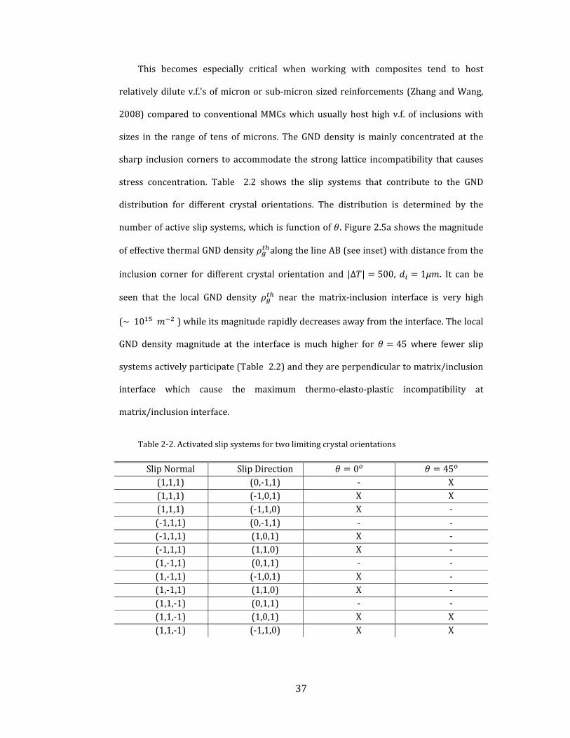
37
This becomes especially critical when working with composites tend to host
relativelydilutev.f.'sofmicronorsub‐micronsizedreinforcements(ZhangandWang,
2008) compared to conventionalMMCswhichusuallyhosthighv.f. of inclusionswith
sizes in the range of tens ofmicrons. The GND density ismainly concentrated at the
sharp inclusion corners to accommodate the strong lattice incompatibility that causes
stress concentration. Table 2.2 shows the slip systems that contribute to the GND
distribution for different crystal orientations. The distribution is determined by the
numberofactiveslipsystems,whichisfunctionof .Figure2.5ashowsthemagnitude
ofeffectivethermalGNDdensity alongthelineAB(seeinset)withdistancefromthe
inclusion corner for different crystal orientation and |Δ | 500, 1 . It can be
seen that the local GND density near the matrix‐inclusion interface is very high
(~10 )whileitsmagnituderapidlydecreasesawayfromtheinterface.Thelocal
GND density magnitude at the interface is much higher for 45 where fewer slip
systemsactivelyparticipate(Table2.2)andtheyareperpendiculartomatrix/inclusion
interface which cause the maximum thermo‐elasto‐plastic incompatibility at
matrix/inclusioninterface.
Table 2‐2.Activatedslipsystemsfortwolimitingcrystalorientations
SlipNormal SlipDirection 0 45 (1,1,1) (0,‐1,1) ‐ X(1,1,1) (‐1,0,1) X X(1,1,1) (‐1,1,0) X ‐(‐1,1,1) (0,‐1,1) ‐ ‐(‐1,1,1) (1,0,1) X ‐(‐1,1,1) (1,1,0) X ‐(1,‐1,1) (0,1,1) ‐ ‐(1,‐1,1) (‐1,0,1) X ‐(1,‐1,1) (1,1,0) X ‐(1,1,‐1) (0,1,1) ‐ ‐(1,1,‐1) (1,0,1) X X(1,1,‐1) (‐1,1,0) X X

38
Figure 2.5b shows the average thermal GND density in the
matrix volume for different ′ and fixed inclusion size ( 1 . Beyond the
initialelasticdeformationstage, changeslinearlywith|Δ |,whichisconsistentwith
the analyticalmodels (Arsenault andTaya, 1987;Dai et al., 1999;Dai andBai, 2001).
Notably, isabout:10 at|Δ | 500,whichisinthesamerangeasevaluated
in experiments (Barlow and Liu, 1998) and predicted from the dislocation punching
modelof(ArsenaultandShi,1986).However,theadditionalinformationthatweobtain
fromthefigureistheeffectofcrystalorientationon .Evenwithisotropicelasticityas
assumed here, higher lattice incompatibility produces higher GND density especially
withincreasing|Δ |.
0 10
30 45
Figure 2.6. Distribution of normal stress under thermal loading for different crystalorientationofmatrix( 1 ).

39
Figure2.6depictsthedistributionofthenormalresidualstress aroundthe
inclusionfordifferent .Itistensileinthevicinityofthetopandbottominterfaces.Note
thatthemaximumtensilestressislargerinthecrystalswithlargerincompatibilityand
willbelargerforsmallerinclusions.Asimilartrendisalsoobservedfor (notshown),
whichistensilealongtheverticalfacesoftheinclusion.Althoughnotexploredhere,the
likelyimplicationonthematrixfailurenucleationarisingfromthenormalstressesdue
to thermal excursion is of interest. The results indicate that the with decreasing
inclusion size and increasing incompatibility, the matrix may become susceptible to
nucleating voids near the interface. Such a possibility may eventually lead to failure
eitherthroughvoidgrowthinthematrixoronethatculminatesintointerfacefailure.
Figure2.7apresentsthermalGNDdensitydistributionfordifferentinclusionsizes
forhighestincompatiblecase( 45 .Itcanbeseenthatforsmallerinclusionsize,the
magnitude of thermal GND density and the area its distributed over are larger.
Consistentwithanalyticalmodels,figure2.7band2.7cconfirmsthelineardependence
of on|Δ |anditsinversedependenceontheinclusionsizeforgiven|Δ |.Whilethe
trends broadly corroborate with analytical models, the simulations provide a deeper
insight into the apportioning of to the thermal mismatch and elasto‐plastic
mismatch,whichisalsoinfluencedbycrystalorientation.

40
1 2
5 10
(a)
(b)
0 100 200 300 400 5000.0
0.1
0.2
0.3
0.4
0.5
1 m inclusion 2 m inclusion 5 m inclusion 10 m inclusion
Magniture of
A

41
(c)
Figure 2.7.(a)EffectiveGNDdensity distributionfordifferentinclusionsizes,(b)averagethermalGNDdensity evolutionduringthermalcoolingfordifferentinclusionsizes,(c)InverserelationofaveragethermalGNDdensity andinclusionsize |Δ | 500, 0 .
Notethatinadditiontothethermalmismatchthatiscommonlyaccountedfor(e.g.
(Arsenault andShi, 1986;Dai et al., 1999;DunandandMortensen,1990;Dai andBai,
2001)),theelasto‐plasticmismatchbetweenthematrixandinclusionalsocontributesto
theGNDdensityunderthermalloading.Thislattercontributionisnotapparentinmost
of the analytical and numerical models. For example, Dai et al. (2001) provide an
expression for the GND density that develops due to elastic mismatch under
mechanicallyappliedstrain,butitsapplicationtotheelasticmismatchstraindeveloped
duringthermalloadingisnotaccountedfor.Toisolatetheseindividualcontributionsto
thermal GND density, we performed additional simulations in that elasto‐plastic
mismatchissuppressed,butthethermalmismatchisretained.Ascanbeseeninfigure
2.8 for theparticular caseof 0 and 1 , isnearly30%higherwhen the
0 2 4 6 8 100.0
0.1
0.2
0.3
0.4
0.5
0.6
Simulation results
Y=ax-1
Inclusionsize, (
Ave.GNDdensity
(
Simulation results

42
elasto‐plasticmismatch is accounted for. This difference is accentuated by increasing
latticeincompatibility.
Figure 2.8.Contributionsofindividualmismatchcomponentsunderthermalloading( 1 .
Figures 2.5b and 2.7c together indicate an interesting interplay between the
inclusionsizeandcrystalorientation.Weobserve thatan increase in theGNDdensity
due to a smaller inclusion could be compensated (at least partially) if the lattice is
oriented in amanner thatproducesweak incompatibility. To first order, these effects
due to thermal excursion may be accounted for in a manner similar to that derived
analytically(DunandandMortensen,1991;Daietal.,2001)
Δ Δ ( 2.15)
where isapre‐factorthatembedstheinformationoftheeffectsofcrystallographically
defined elastio‐plastic properties of the matrix and the inclusion shape. For square
inclusions,comparingEq.2.15withthesimulationresults(Fig.2.5b), 30 40,with
0 100 200 300 400 5000.0
0.1
0.2
0.3
0.4
0.5
0.6
Thermal+Elastoplastic GND Thermal GND
Thermalmismatch
Elasto‐plasticmismatch
Magniture of
A
Thermo-elasto-plastic mismatch Thermal mismatch

43
the lower bound delimited by the lowest lattice incompatibility (e.g. 0 in our
simulations) and theupperboundby thehighest lattice incompatibility (e.g. 45 )
withrespect to the loadingaxis.Note that thepre‐factor isnearly thrice thatof the
analyticallyobtainedcoefficient(Daietal.,2001).
2.3.3 Size-dependent stress-strain response with pre-existing
thermal GND density
Followingthethermalprocessingthatproduceresidualstresses,theMMCbehavior
under compressive and tensile mechanical loads could differ significantly.For
conventional coarse‐grainedMMCswith large inclusions,the thermal residual stresses
provide a basis for the tension‐compression asymmetry in the stress‐strain
response.This isalsoexpected inMMCswith fine‐scaled inclusionswithanadditional
complexityarisingfromtheirsize‐dependency.Asnotedintheintroductorypartofthis
section,we subjected the same MMC unit cells to monotonic tension and
compression(Fig.2.9).The solid curves in figure2.9are the average true stress‐true
strainMMCresponses intensionandcompressioninthepresenceof locked‐in length‐
scale dependent thermal residual stresses 1 , 0.05, 45° .The
classicalcrystalplasticity(CCP)results(i.e.ignoringtheslipgradients)areshownbythe
dashedcurves for thesame and .Notethat thestress‐straincurvesareplottedup
to1%strainonly,inorder tohighlight theeffectofpriorthermal residualstresseson
theinitialstrengtheningandhardening.Inbothcasesthethermalresidualstresseslead
toanasymmetry in the tensileandcompressiveresponses,indicating theirubiquitous
role irrespective of whether size‐effects are accounted for or not.Specifically,the
compressive response is stronger compared to the tensile response,because the
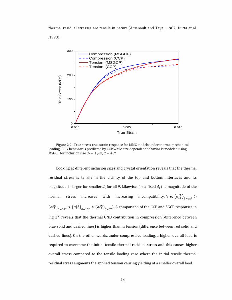
44
thermal residualstressesare tensile innature(ArsenaultandTaya ,1987;Duttaetal.
,1993).
Figure 2.9.Truestress‐truestrainresponseforMMCmodelsunderthermomechanicalloading.BulkbehaviorispredictedbyCCPwhilesizedependentbehaviorismodeledusingMSGCPforinclusionsize 1 , 45°.
Lookingatdifferentinclusionsizesandcrystalorientationrevealsthatthethermal
residual stress is tensile in the vicinity of the top and bottom interfaces and its
magnitudeislargerforsmaller forall .Likewise,forafixed themagnitudeofthe
normal stress increases with increasing incompatibility, . .
.AcomparisonoftheCCPandSGCPresponsesin
Fig.2.9reveals that the thermalGNDcontribution in compression(differencebetween
bluesolidanddashedlines)ishigherthanintension(differencebetweenredsolidand
dashed lines).On theotherwords,under compressive loading,a higheroverall load is
required toovercome the initial tensile thermal residual stressand thiscauseshigher
overall stress compared to the tensile loading case where the initial tensile thermal
residualstressaugmentstheappliedtensioncausingyieldingatasmalleroverallload.
0.000 0.005 0.0100
100
200
300
Compression (MSGCP) Compression (CCP) Tension (MSGCP) Tension (CCP)
Tru
e S
tres
s (M
Pa)
True Strain
Compression (MSGCP) Compression (CCP) Tension (MSGCP) Tension (CCP)

45
(a) (b)
Figure 2.10.Influenceofthepriorthermalloadingon(a)truestress‐truestrainresponseand(b)hardeningrate.( 1 , 45°),obtainedfromMSGCPcalculations.
Figure2.10 indicates that the hardening rate in tension is higher than that in
compression,atleastintheinitialstagesofplasticity.Tofurtherstudytheevolutionof
hardeningduetothermo‐mechanicallyinducedGNDeffects,wecomparethehardening
rates of the two‐step thermo‐mechanical loading for monotonic tension and
compressionwiththatofthemechanical‐onlyloadingcase.Notethatinthemechanical‐
onlycasetheresponseisthesameundertensionandcompression.Figure2.10ashows
influence of prior thermal loading on the subsequent stress‐strain response under
tensileandcompressivemechanical loadingwhencomparedwith themechanical‐only
loadingcaseandfigure2.10bshowsthecorrespondinghardeningrates / .Itcanbe
seen that in the presence of initial thermal loading the subsequent tensile yield
strength(measured at0.2%strain)is lower,but the overall hardening rate is higher
compared to the mechanical‐only loading over the strain range considered.On the
contrary,thecompressiveyieldstrengthishigherandthehardeningrateisalsohighin
theincipientstage,butwithincreasingstrainthelatterquicklydropsbelowthetensile
response and asymptotes toward the hardening rate of the mechanical‐only loading
condition.These observations may be rationalized as follows:at the initial stages of
0.000 0.002 0.004 0.006 0.008 0.0100
50
100
150
200
250
Tru
e S
tres
s (M
Pa
)
True Strain
Thermo-Mechanical (compression) Thermo-Mechanical (tension) Mechanical
0.002 0.004 0.006 0.008 0.0100
20000
40000 Thermo-Mechanical (compression) Thermo-Mechanical (tension) Mechanical
Ha
rden
ing
rate
(M
Pa)
True Strain
Thermo-Mechanical (compression) Thermo-Mechanical (tension) Mechanical

46
compressive loading,macroscopic compressive stresses at the inclusion‐matrix
interfaces are compensated by the initial tensile thermal residual stresses generated
duringthethermalloadingattheinterface(figure2.11).Naturally,thenetlocalstresses
at the interface are lowered and therefore,the applied stress has to be increased for
macroscopic yielding(Fig.2.10a).Then,for the same strain the stress is higher in the
thermal plus compressive loading case compared to themechanical‐only loading case
and consequently,the initial hardening rate in the former is higher.The rapiddrop in
the compressive hardening rate indicates that the strengthening effect due to prior
thermal residual stresses decreases with increasing strain.This may be construed as
some of the initial thermal GND density being annihilated by the mechanical GND
densityaccumulatedduringthesubsequentmechanicalloading.
Figure2.11showstheevolutionoftotal(thermal+mechanical)GNDdensityforthe
tensileandmechanicalloadingcases.IntheinitialstagesthetotalGNDdensityisnearly
the same as that developed during prior thermal history. However, as deformation
progressesweobserveadropintheGNDdensityundercompressiveloadingindicating
partial annihilation of thermal GNDs; in comparison, under tensile loading the GND
densityincreasesmuchmorerapidly.Inotherwords,thelatticecurvaturegeneratedat
theinclusion‐matrixinterfaceduetothermalloadingiscompensatedbythatgenerated
due to the mechanical loading. As the loading continues, the mechanically‐induced
latticecurvature(mechanicalGNDdensity)prevailsovertheinitialthermalGNDdensity
andgoverns themacroscopichardening.Asmentioned in theprecedingparagraph, in
thecaseoftension,theexternaltensilestressarisingfromthemechanicalloadingadds
totheinitialtensilethermalresidualstresses.ThisnaturallycausestheMMCtoyieldat
alowerappliedload,butasdeformationprogressesmechanicalGNDdensityaddstothe
initialthermalGNDdensityproducinganenhancedhardeningrate.

47
Figure 2.11.AverageGNDdensityevolutionunderconsequentthermal‐mechanicalloading.( 1 , 45°)
2.3.4 Inclusion shape effect on stress-strain responses in the
presence of thermal GND density
TheoreticalstudiesonMMCreveal thatoverallMMCresponse isstronglyaffected
by inclusion shapes. (Meijer, 2000) used a cubic unit cell to investigate the residual
thermalstress/straininparticulatereinforcedmetalmatrixcomposites.Theyfoundthat
the sharp corners and edges of the cube shaped particles result in stress/strain
localization and lead to a much larger initial hardening behavior than the spherical
inclusions. (Chen et al., 1999) extensively studied effect of inclusion shape and its
morphology on the MMC response. They showed that the plastic strain near the
inclusion‐matrix interfacevarieswith inclusionshape.Whenthecurvatureatacorner
increasestheplasticstraingetsmoreconcentratedarounditandhasasignificanteffect
onthethermalresidualstressandstraindistributions.(Xueetal.,2002)observedthat
thereisarelativelyweakinteractionbetweeninclusionsizeandshapeforinclusionsize
largerthan7.5 whenthethermalresidualstressesareignored.Here,weinvestigate

48
the coupling between the inclusion size and shape in the presence of initial thermal
loading.Todoso,weperformthetwo‐stepthermo‐mechanicalsimulations forsquare
and circular inclusions, with 0.05, which gives 1 and
1.13 .
Figure2.12showsthecrystalorientation‐dependentthermalGNDdistributionfor
thetwoinclusionshapesandcorrespondingactiveslipdirections.Forboththeshapes,
large incompatible deformations result in high GND density in the vicinity of i‐m
interface,whichisdistributedinthedirectionofslipsystems.Quantitatively,thespatial
extentoftheGNDaffectedzonesaresimilarforboththeinclusionshapes;however,the
GNDdensityismoreconcentratednearthesharpcornersforthesquareinclusion.
(a)
(b)
Figure 2.12.DistributionofthermalGNDdensityaroundsquareandcircularinclusionsembeddedinsinglecrystalwith(a) 0°and(b) 45°.

49
Studieson theeffectof inclusion shapeusingcontinuumplasticityhave indicated
thathigher triaxialityof the stress‐stateexists ata sharpcornerof a square inclusion
comparedtothestressstateinthecloseproximityofacircularinclusion.Thisraisesthe
overallstress‐strainbehavioroftheMMCswithsharp‐corneredinclusionscomparedto
thosewithmoreroundedinclusions(Meijer,2000).Interestingly,wefindthesituation
to be somewhat different when the GND effects are included.Figure2.13shows the
MSGCPtruestress‐truestrainresponsesofMMCunderthermo‐mechanical loadingfor
the square and circular inclusions embedded in single crystal with 0.05and
0° .For comparison,the CCP results are also included in the same plot with same
simulation parameters.The CCP results show that the shape of inclusion has an
influence on the overall stress‐strain behavior with the square inclusion providing a
strongerresponsethanitscircularcounterpart.Thisisqualitativelyconsistentwiththe
trendindicatedby(Meijer,2000).However,theshapeeffectdramaticallyreducesinthe
presenceofthethermalGNDdensity.
Figure 2.13.Truestress‐truestrainresponseforMMCmodelscomprisingtwodifferentinclusionshapes 0° .
0.000 0.005 0.010 0.015 0.020 0.0250
50
100
150
200
250
300
350
Tru
e st
ress
(M
Pa)
True strain
CCP- Square inclusion CCP- Circular inclusion MSGCP- Square inclusion MSGCP- Circular inclusion

50
The diminished shape effect in the presence of thermal GND density can be
explainedintermsoftheinteractionbetweentheGNDaffectedzoneati‐minterfaceand
the high triaxiality stress at a sharp corner.Figure2.14shows the von‐Mises stress
distributions around the square and circular inclusions as obtained from theCCPand
MSGCP calculations.The CCP simulation, being length‐scale independent, does not
accountforthethermalGNDdensityandisakintoalargeinclusioncasewheretheGND
effectsarenegligible.Note that thesimulationresultsare for 0°,whichpossesses
thelowestincompatibilityamongstthecasesevaluatedhere(seeforexample,Fig.2.5a),
whichmeansthatthethermalGNDdensitywouldalsobethelowest.Eveninthiscase,
astheinclusionsizedecreasesthestressintheGNDaffectedzonetendstooverlaythe
regionsofhightriaxiality(sharpcorners)sothattheregionaroundthesquareinclusion
appearstohavemoredistributedstressarounditcomparedtothecasewhereeitherthe
thermally induced GND density is not present or is negligible. Figure 2.15 further
elaboratesthisideaschematically,indicatingthatthestressconcentrationsatthesharp
corners tend to be engulfed by overall high stress around a square inclusion as the
inclusionsizedecreases.Thistemperstheeffectofinclusionshapeonthemacroscopic
behavior,becausethestressstatearoundasharp inclusionappearstobequalitatively
closer to that of an inclusionwith rounded corners, the limiting case being a circular
inclusion. We note in passing that we observe qualitatively similar trends for the
45°andarenotrepeated forbrevity. Inconclusion, thesimulationsreveal that in
the presence of initial thermal GND density the inclusion shape effect on the overall
MMC response diminishes at smaller inclusion sizes. In addition to this, although the
stress around the inclusion is higher it is relatively more uniformly distributed
comparedtothecasewheretheGNDeffectisabsentandthisisexpectedtoshieldsucha
materialagainstfracturearisingfromlocallyhighstresses.

51
(a)
(b)
Figure 2.14.InfluenceofinclusionshapeonthermalresidualstressesinMMCbasedon(a)CCPand(b)MSGCP. 0°
Figure 2.15.Schematicindicatinganinteractionbetweeninclusionshapeandsizeeffectsatthelocationsofstressconcentrations.
GND affected zone
Stress concentration
>

52
2.3.5 Thermal GND density distribution in polycrystalline MMC
under thermal loading
In the previous sections, the role of inclusion size and crystal orientation are
investigated using unit cell model comprising a single inclusion embedded inside a
singlecrystalmatrix.Inthissection,weexploretheapplicabilityofthemodelonMMC
with polycrystallinematrix where grain sizes are smaller than inclusion sizes. In the
next section we will investigated the role of grain size, inclusion size and their
interaction in MMC overall response undermechanical loading via mechanism based
straingradienttheory.Here,weadoptunitcellapproachincludingboththethermaland
theelasto‐plasticmismatchesbetweenthegrainsaswellastheinclusionandthegrains
surrounding it (figure 2.16). The crystallographic elastic properties for the grains are
168.4, 121.4and 75.4 .Thecolorsforindividualgrainsrepresent
their orientation as specified by the numerals within the grains surrounding the
inclusioninFig.2.16.ThecontourplotsinFigs......aandbrespectivelyshowthethermal
GNDdensity distribution grain sizes 0.5 and0.25 . Inboth case, 0.05 ,
and 1 .
As a comparison, Fig. 2.17 shows the evolution of the average thermal GND
densities inthepolycrystallineMMCanditssinglecrystalcounterparts.First, itcanbe
seenthattheaverageGNDdensityishigherinthecaseofpolycrystallineMMCsasthe
grain boundaries act as additional sources of elasto‐plastic incompatibility.
Interestingly, this enhancement is only weakly dependent on the grain size. This
indicates that the elastic anisotropy in polycrystalline matrices do not produce a
significantcouplingintothegrainsize‐dependenceofthethermalGNDdensity.Second,
weobserveisthatthefinergrainsizeproducesamoreuniformdistributionoftheGND
density, which is also important because it can help induce uniform strengthening
aroundtheinclusion.Finally,notethatthesinglecrystalcasesgivealowerGNDdensity,

53
eventhatwiththelargestincompatibility 45 .Fromthis,wemayconjecturethat
for highly textured polycrystalline cases (a limiting case being a single crystal) the
thermal GND density may be somewhat lower than a poylcrystal MMC with random
texture.Inotherwords,texturedpolycrystalsmayproduceweakerinitialstrengthening
duetothermalhistorycomparedtoarandomlytexturedpolycrystalMMC.
(a)
(b)
Figure 2.16.EffectiveGNDdensitydistributioninpolycrystallineMMCwithrandomgrainorientationfordifferentgrainsize(a) 0.5 μmand(b) 0.25 μm. 1 , |Δ | 500

54
Figure 2.17.AverageGNDdensitydistributionevolutioninsinglecrystallineandpolycrystallineMMC
2.4 Grain size-inclusion sizes interaction in MMC at
moderate strain using MSGCP
Mostof thepreviousefforts onMMCbehaviors andunderlyingmechanismshave
beenconcentratedontheunitcellapproacheswhereasingleinclusionrepresentingits
v.f., is embedded in a single crystal or a homogenized matrix that is endowed with
enrichedplasticitydescriptions.However,itisimportanttonotethelimitationsofthese
models in terms of the microstructural characteristics: an inclusion embedded in a
singlecrystalresemblesapolycrystallinemasswhosegrainsaremuchbiggerthanthe
particles(Cleveringaetal.,1997)sothatthegb’sdonotinterfereinthestrengthening
response (e.g. a sub‐micron sized inclusion embedded within a large grain of a
polycrystal). The other extreme is the assumption of a homogenized matrix with
discrete inclusions (Nan and Clarke, 1996; Suh et al., 2009; Xue et al., 2002), which
0 100 200 300 400 5000.0
0.2
0.4
0.6
0.8
PolyX, dg=0.25 m
PolyX, dg=0.5 m
SingleX, = 45o
SingleX, = 0o
Magniture of
A

55
resembles a polycrystalline mass with grains that are much finer (allowing
homogenization of the matrix) than the inclusions. In practice, one may encounter
important intermediate cases in addition to these two extremes, especially for
nanostructured composites. For example, the trimodal Al‐alloy composites (Joshi and
Ramesh,2007;Zhangetal.,2008)possessgrainsizesthatareinthesamerangeasthose
ofthereinforcingparticles(Figure 2.18).Insuchsituationsitmaynotbeappropriateto
assume either a homogenizedmatrixmodel or a single crystal approximation. Rather
one has to explicitly resolve both inclusion and its surrounding grains within the
microstructuretocapturethelength‐scaledependenciesontheoverallresponse.
Figure 2.18.MMCwithmicron‐sizedinclusionsembeddedinananocrystallinematrix(JoshiandRamesh,2007)
Thisobservationposesinterestingquestions–whatrolesdothegrainsizeandthe
inclusionsizeplayintheoveralllength‐scaledependentresponseofanMMC?Howdoes
one account for or model the interaction between these microstructural features? Is
there a range of grain size‐inclusion size combinations that produces significant
synergistic contributions? Is itpossible toquantify this interaction, forexample, asan
additional hardening contribution? To our knowledge, these questions have not been
addressedviaeitheranalyticalorcomputationalmodelingatanylength‐scale.
56
From amechanistic viewpoint this is a challenging problem as there are several
aspectsthatonehastounderstand,forexample,thephysicsoftheplasticeventsatthe
inclusion‐matrix (i‐m) interfaces and at gb’s (and triple junctions), communication
between the i‐m interfacesandgb’s, grainorientation effects, inclusionandgrain size
distributions, and several more. While it may be important to incorporate these
mechanisms, a single mechanistic framework that is capable of resolving the
microstructural details and concurrently also embeds appropriate physics for all the
interfacialmechanismsisdifficulttoconceiveatthemoment.Acomparativelytractable
settingispossibleifonechoosestosimplifyand/orignoresomeoftheaspects.Crystal
plasticity enriched with length‐scale features can effectively handle the kind of
resolutionnecessaryfortheproblem.Initssimplestversion,itispossibletomodelMMC
microstructures using CP by explicitly resolving the grains and inclusions and
accounting for some of the size‐dependent mechanisms, but ignoring some of the
intricate details such as size and spatial distributions of grains and inclusions, gb
deformationprocessesandfailure3.
Withthisnotion,wedemonstrateacomputationalapproachbasedonlength‐scale
dependent crystal plasticity (CP) to answer the questions posed in the preceding
paragraph.Specifically, thisworkresorts tothemechanism‐basedslipgradientcrystal
plasticity (MSGCP) (Han et al., 2005a) theory. MSGCP accounts for size‐effects by
incorporatingslipgradientsthatarerelatedtotheGNDdensitieswithintheconstitutive
description of individual slip systems. Given that both grains and inclusions are
explicitly resolved in this approach, slip gradients naturally arise at gb’s and i‐m
3ThesedetailscanbeincludedwithinCP,buttheycomplicatetheproblembyintroducing
severaladditionalvariablesandunderstandingtheireffectsontheoverallbehaviorwould
requiresignificantcomputationaleffort.

57
interfacesduetheirelasto‐plasticmismatchandareaccountedforintheMSGCPtheory.
However,this approachisessentiallyalower‐ordertheorycomparedtoahigher‐order
framework, because it does not invoke additional boundary conditions (b.c.’s) at
interfaces. Consequently, the lower‐order CP approaches cannot model some of the
enhanced interactions between interfaces and dislocations that the higher‐order CP
approachesarecapableofhandling.Althoughahigher‐ordertheorywouldbesuitedfor
the present problem (Fredriksson et al., 2009), (Bardella and Giacomini, 2008), the
difficulty with higher‐order b.c.’s is that it may not be always easy to identify
appropriate descriptions for general interfaces (Voyiadjis and Deliktas, 2009).
Moreover,thecomputationaleffortforhigher‐orderCPissignificantlylargerthantheir
lower‐ordercounterparts.Ontheotherhand,duetotheinherentinabilityoftheMSGCP
inhandlingenhancedinteractionsbetweeninterfacesanddislocationsthelength‐scale
effect appears only in the flow behavior rather than at yield (Evans and Hutchinson,
2009).However,despitesomeofitslimitations,wechoosetheMSGCPtheorykeepingin
view its simplicity in the numerical implementation within existing CP framework,
computational expense for the present work and a relatively established physical
understandingofthelength–scaleparameters.Inthisregard,theresultspresentedhere
on the grain size‐inclusion size interaction are applicable in the flow regime, i.e at
moderatestrains,ratherthanatyield(AcharyaandBeaudoin,2000).However,wealso
notetheexperimentalobservationof(KouzeliandMortensen,2002)thatthesizeeffect
intheflowregimeofMMCsfollowssimilartrendsasatyieldandreturntothisaspectin
theclosingsectionofthischapter.
Inthenextsection,wedescribethemodelmicrostructuresadoptedinthepresent
work and the procedure to isolate the individual length‐scale effects arising from the
grainsize,inclusionsizeeffectsandthegrainsize‐inclusionsizeinteractions.

58
2.4.1 Model Microstructures
Toenableconsistentcomparisonacrossdifferentparametricmodels,weconsider
highlyidealizedMMCmicrostructurescomprisingsquaregrainsandinclusions.Wealso
assume that the inclusions are regularly arranged, and the gb’s and interfaces remain
intactthroughoutthedeformation.Figure 2.19showscanonicalpolycrystal(Figure 2.19
a, c) andMMC (Figure 2.19 b, d) microstructures amongst several considered in the
presentwork.Oneextremecaseiswheretheinclusionismuchsmallerthanthegrainso
that iteffectivelyresideswithinthegrain(Figure 2.19b),andtheothercase iswhere
theinclusionismuchbiggerthanthegrains(Figure 2.19d)sothatmultiplegrainsshare
aninclusioninterface.Agrainorientation(Figure 2.19a)forthisFCCcrystalstructureis
definedhere as the anglemadeby the [100] crystal directionwith the global loading
direction and [001] crystal direction is considered to coincidewith the global
direction. The associated color for each grain acts as a reference for the other
microstructures4. Within each MMC configuration the grain size and inclusion
size areconstant.Thisenablesorganizingthemicrostructuralarrangementsintotwo
broadcategories:(a) (Figure 2.19c),and(b) (Figure 2.19d).
4 Insection2.4.6webrieflydiscussthestatisticaleffectofthenumberofgrainswith
randomgrainorientationsonthestress‐strainresponses.

59
(a) (b)
(c) (d)
Figure 2.19.Representativemodelsfor(a,c)polyXand(b,d)MMCarchitectures.
Forcase (a)weconstructa36grainpolycrystalwithrandomcrystalorientations
witheachgrainembeddingoneinclusion.Forcase(b)asingleparticleissurroundedby
randomly oriented grains. Note that only when ≫ would a computational cell
asymptote to a unit cell approximation that is commonly adopted (Dai et al., 2001a;
KouzeliandMortensen,2002;NanandClarke,1996;Zhangetal.,2007)however,most
worksdonotstatetheassumptionsonthematrixmicrostructuraldetailsexplicitly. In
such cases, it is not obvious how the matrix strengthening due to grain size would
couplewiththecontributionfrominclusionsize.Toquantifythegrainsizeandparticle
sizeeffects:
47 38 78 5 19 42
85 83 38 55 22 21
64 7 40 37 15 58
47 34 67 72 58 6
68 16 67 14 66 76
75 40 3 34 58 15
6gd m
2id m

60
(i)First,wemodelpolycrystallinemasses comprisinga fixednumberof grainsof
size ,without inclusions (c.f. Figure 2.19 a, c). These simulations are performed for
microstructureswithdifferentgrainsizes,butkeepingtheinitialorientationsbetween
thedifferentmicrostructuresunchanged.
(ii) The samemicrostructures in (i) are again simulated with inclusions of fixed
size andvolumefraction (e.g.Figure 2.19bandd).
Steps(i)and(ii)areappliedtodifferentinclusionsizeswithfixed ,Basedon(i),
theflowstress ofabarepolycrystallinemassatafixedstrainis
∆ ( 2.16)
where isthesize‐independentflowstressofthepolycrystallinemasswithlargegrain
sizesforagivensetofcrystallographicorientation,andΔ istheadditionalgrainsize‐
dependentflowstressderivedfromtheslipgradientsatgb’s.Likewise,fromstep(ii)the
flowstressforanMMC maybewrittenas
Δ
∆ Δ
Δ
Δ Δ Δ
( 2.17)
whereΔ isthesize‐independentflowstresspurelyduetotheinclusionv.f.,Δ isthe
contributionduetoinclusionsizeeffectarisingfromtheslipgradients(GNDs)atthei‐m
interface andΔ is an additional contribution thatmayexist due to the synergistic
effectsbetween and .NotethatthegrainsizecontributioniscommontoEqs.( 2.16)
and( 2.17).
Forall the cases, the left andbottomedgesare respectively constrained along
and directions, the top edge is allowed to move vertically, but remain straight. A
uniform velocity b.c. is applied to the right edge producing a nominal strain

61
rate 1 10 . Inwhat follows,we refer to thepolycrystallinemicrostructures
sans inclusionsasPolyX and thosewith inclusionsasMMC.Table1gives thematerial
propertiesusedinthesimulations.ThesepropertiesarerepresentativeofpureAlasthe
matrixandSiCasthe inclusions.Forsimplicity,weassumeisotropicelasticproperties
fortheAl,butanisotropicelasticitycanbeeasilyimplemented.
2.4.2 Length-scale dependent polycrystalline response
Figure 2.20showsthesize‐dependentpolyXtruestress‐truestrainresponseswith
differentgrainsizes.Thereddashedcurveisthebaselinecalculationwithoutgradient
effectsthatrepresentsapolyXwithlargegrains.Asnotedearlier,thenatureoftheslip
gradientmodelimplementedhereissuchthatthelength‐scaleeffectmanifestsitselfin
the hardening response rather than at yield (Evans andHutchinson, 2009;Han et al.,
2005a). Therefore, we measure the average flow stress at 2% nominal strain to
demonstratethesizeeffects.Figure 2.21showsthestrongdependenceoftheflowstress
on .Theplotalso includes thepopularHall‐Petch typeempirical fit ~ . to the
simulation results alongside the inverse grain size correlation . (Acharya and
Beaudoin, 2000) applied their version of the length‐scale dependent CP theory to
investigate grain size effects in polycrystals and obtained corroborations with
experiments at moderate strains. Experimental evidences (Hommel and Kraft, 2001;
Nix, 1989; Venkatraman and Bravman, 1992) and theoretical models (Ohno and
Okumura,2007;Sinclairetal.,2006;Zhangetal.,2007;Zhouetal.,2011)makecasesfor
boththetypesofdependencies,butforconsistentcomparisonhereweadopttheHall‐
Petchrelationforsubsequentdiscussions.

62
Figure 2.20.Truestress‐truestrainresponsesforpolyXmodelswithdifferentgrainsizes.
Figure 2.21.Normalizedgrainsizedependentflowstressat 2% forpolyXwithidenticalgrainorientations.TheplotalsoincludestheempiricalHall‐Petch . andinversegrainsize fits.
Decreasinggrainsize
0
50
100
150
200
250
300
350
0 0.01 0.02 0.03 0.04 0.05
CCP
dg= 6 m
dg= 1 m
dg= 500 nm
dg= 300 nm
Tru
e S
tre
ss (
MP
a)
True strain
0
2
4
6
8
10
12
0.1 1 10
g /
Y )
*10
0
Grain size, dg
( m)
Simulation results
Hall-Petch behaviour
Inverse grain size relation
Simulation results
Hall-Petch fit
Inverse grain size fit

63
2.4.3 Length-scale Dependent MMC Response
We now discuss the results obtained from the MMC simulations. For clarity, we
focusinitiallyonthecasewithfixed 2 anddifferent ′ 6 and1 ,but
subsequentlyalsodiscusstheeffectofinclusionsize.Figure 2.22showstheresponseof
MMCs(solidcurves)fordifferentgrainsizes.Forcomparison,thepolyXresultsforthe
samegrain sizesandorientationsarealso included in the figure (dashedcurves).The
red dashed and solid curves respectively denote the response of the polyX andMMC
without the gradient effects (i.e. conventional crystal plasticity). As expected,
irrespectiveofwhethergradientsareincludedornottheMMCflowstressishigherthan
itspolyX counterpartdue to thepresenceof inclusions in the former Δ . Theblue
solid curve is theresponseofanMMCwith inclusions thataremuchsmaller than the
grains(e.g.Figure 2.19b),whereasthegreensolidcurveisforthecasewherethegrains
are smaller than the inclusions (e.g. Figure 2.19 d). Interestingly, in the presence of
gradients,thelatterexhibitsahigherhardeningrateoveritspolyX(dashedgreencurve)
counterpartcomparedtotheformer(solidanddashedbluecurves).Thissuggeststhat
thereexistsaninteractionbetweenthegb’sandthei‐minterfaceswhenthegrainsizes
are comparable to or smaller than the inclusion sizes. In the following section, we
quantify this interaction through systematic simulations with different grain and
inclusion sizes. In the next section, we briefly discuss the mesh convergence studies
performed on one combination.
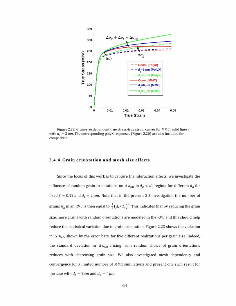
64
Figure 2.22.Grain‐sizedependenttruestress‐truestraincurvesforMMC(solidlines)with 2 .ThecorrespondingpolyXresponses(Figure 2.20)arealsoincludedforcomparison.
2.4.4 Grain orientation and mesh size effects
Sincethefocusofthisworkistocapturetheinteractioneffects,weinvestigatethe
influence of random grain orientations onΔ in regime for different for
fixed 0.12and 2 .Note that in thepresent2D investigation thenumberof
grains inanRVEisthenequalto ⁄ .Thisindicatesthatbyreducingthegrain
size,moregrainswithrandomorientationsaremodeledintheRVEandthisshouldhelp
reducethestatisticalvariationduetograinorientation.Figure 2.23showsthevariation
inΔ ,shownbytheerrorbars, forfivedifferentrealizationspergrainsize.Indeed,
the standard deviation in Δ arising from random choice of grain orientations
reduces with decreasing grain size. We also investigated mesh dependency and
convergencefora limitednumberofMMCsimulationsandpresentonesuchresult for
thecasewith 2 and 1 .
0
50
100
150
200
250
300
350
0 0.01 0.02 0.03 0.04 0.05
Conv. (PolyX)
dg=6 m (PolyX)
dg=1 m (PolyX)
Conv. (MMC)
dg=6 m (MMC)
dg=1 m (MMC)
Tru
e S
tre
ss (
MP
a)
True Strain
∆ ∆ ∆
∆ ∆

65
Figure 2.23.StandarddeviationinΔ arisingforagivencomputationalmodelwithfixed butdifferentrealizationsofgrainorientations.Asexpected,thevariationissmallerforfiner .
Figure 2.24ashowsthatthestress‐straincurvesconvergewithfinermeshsize. In
addition, the flow stress at a true strain of 0.04 is depicted versus total number of
elementsusedinthemodelinFigure 2.24b.
(a) (b)
Figure 2.24.Meshconvergenceforthestress‐straincurvesofMMC 2 ,1 withdifferentmeshsizes .
0
2
4
6
8
10
12
14
16
0 0.5 1 1.5 2 2.5
it/ 2
2
(MP
a)
4 6 8 10 12
Grain size, dg (m)
in
t/
0
50
100
150
200
250
300
350
0 0.01 0.02 0.03 0.04 0.05
d = 240 nm d = 120 nm
d = 60 nm d = 30 nm
300
305
310
315
320
325
330
0.03 0.035 0.04 0.045 0.05
Finer mesh
True strain
Tru
e st
ress
(M
Pa)
311
312
313
314
315
316
317
318
319
0 1E+4 2E +4 3E+4 4E+4
Flo
w s
tre
ss a
t 4
% s
trai
n (
MP
a)
No. Elem ent

66
2.4.5 Grain size-inclusion Size Interaction strengthening
Tosystematicallydiscerntheinteractioneffectthatexistswhentheinclusionsizeis
inthesamerangeorsmallerthanthegrainsize,weperformedFEsimulationsofMMCs
with various grain size‐inclusion size combinations (see Table 2‐3). The procedure
adopted is discussed here brieflywithin the context of a fixed , and . First, two
simulations are performed for the MMC with both SGCP and conventional crystal
plasticity(CCP).Thealgebraicdifferencebetweentheoverallstress‐strainbehaviorsof
these two gives the totalMMC strengthening Δ Δ Δ due to
thegrainsize,inclusionsizeandinteractionterms(Eq.( 2.17).ThegrainsizeeffectΔ
is obtained as the difference between the polyX‐SGCP and polyX‐CCP response that
possess the same grain sizes and orientations as the MMC. Subtracting the 1
portion of the grain size effectΔ from the total MMC strengtheningΔ , the
combined inclusion size and interaction effects are isolated, i.e. Δ Δ .
Thisprocedureisperformedfordifferentgrainsizesandinclusionsizeswithfixed .
Table 2‐3.MicrostructuralsizecombinationsforMMCsimulations
InclusionSize
5 2 1
GrainSize
0.83,1.6,5,15 0.33,0.66,1,2,6,15 0.33,0.5,1,3,15
Figure 2.25 shows the normalizedΔ as a function of at 2% nominal strain
for 1 , 2 and5 .Notethatstrengtheningbehaviorcanbesplitupintotwo
distinct regions. The first region is , characterized byΔ that is larger for
smallerinclusionsizes.Inthisregime,thecurvesremainhorizontalandparalleltoeach
other over the range,meaning that the grain size does not play anymajor role in
contributingtotheoverallMMCstrengthening.Inotherwords,for theinclusion

67
strengthening is grain‐size independent and only inclusion size‐effect prevails. To
extracttheinclusionsizeeffect,weconsidercaseswith 3 wheretheinteraction
effectisnegligible.
Figure 2.25.Flowstress 2% normalizedbybulkpolyXyieldstressvariationofMMCsasafunctionofgrainsize.
ItcanbeseenthatinFigure 2.26thattheflowstressvariesas . ,whichcanbe
explainedbyTaylorhardeningdescription that is embedded in theMSGCP (Dai et al.,
2001a)
Δ √3 √36
( 2.18)
where istheTaylorfactorand isthematrixshearmodulusand istheapplied
strain.

68
Figure 2.26.Inclusionsizeeffectonthenormalizedflowstress(normalizedbybulkpolyXyieldstress)forlargegrainsizes, 3 (negligiblegrainsizeeffect).
The second regime in Figure 2.25 corresponds to where a dramatic
increaseinstrengtheningisobserved,whichmustbeduetotheinteractionbetweenthe
i‐minterfacesandgb’s.Inthisregime,theinteractioneffectforagiven issimplythe
deviationofthecurvefromitsbaselineinclusionstrengtheningatlargegrainsizes,i.e.
Δ Δ Δ . Note that for a fixed the interaction effect is larger for
smaller . Further, for smaller inclusions the interaction effect kicks in at
correspondingly smaller grain sizes. In other words, the inclusions do not feel their
neighboring grains unless the characteristicmicrostructuralwavelengths of the latter
arecomparableorsmallerthantheformer.
ThemannerinwhichtheGNDdensitycomponentofthetotaldislocationdensityis
distributed depends strongly on the grain size and the inclusion size. As an example,
Figure 2.27showstheGNDdensitydistributionsalonganodalsegmentstaringfroman
i‐m interface traversing through the matrix for three cases with different ′ and
fixed .Clearly,thepresenceofmultiplegb’s(smallergrains)aroundaninclusionleads
0
1
2
3
4
5
0 1 2 3 4 5 6
i/ y )
1
00
Particle size, di (m)
Simulation results
Equation 3

69
toahigherGNDdensityatthei‐minterfaceaswellasGNDaccumulationatthegb’s.This
effectisfurtherenhancedforsmallerinclusionsizes(notshownhere).
Figure 2.27.DistributionoftheeffectiveGNDdensity / alongpatha‐b 2 fordifferentgrainsizes.
Wepositthattheintersectionofagbandaninclusioninterfacecanbeconsidered
asanadditionalsourceofdislocationactivitythatleadsincreasingdislocationdensityin
itsvicinityandcontributestotheoverallhardeningasaninteractioneffect,Δ .Inthe
nextsection,weproposeananalyticalmodelbasedonthishypothesistoaccountforthe
dependenceofΔ onboththegrainsizeandtheinclusionsize.
Interaction effects discussed in the context of MMCs have also been observed in
polycrystalline thin films on substrates. There, strong interactions exist between the
gb’s and the relatively rigid substrates. Although these effects have been addressed
based on the grain sizes and film thickness, they have mostly been accounted for
separately rather than as an interactive effect (Hommel and Kraft, 2001; Nix, 1989;
Venkatraman andBravman, 1992). Interestingly, (Hommel andKraft, 2001) indicated
λ
0.0E+00
1.0E+03
2.0E+03
3.0E+03
4.0E+03
5.0E+03
6.0E+03
7.0E+03
8.0E+03
9.0E+03
0 0.1 0.2 0.3 0.4 0.5 0.6 0.7 0.8 0.9 1
dg=0.66um dg=1um dg=6um
a b
x/λ
GBs
μm μm μmE
ffec
tive
GN
D d
ensi
ty -η/
b (1
/μm
²)

70
that the dislocation density measured in their film‐substrate experiments was larger
than the computed total dislocationdensity,which is summation of the SSDandGND
densities. Furthermore, (Choi and Suresh, 2002; Nicola et al., 2005) pointed out that
grain size and film thickness are coupled and not independent. Hence, a linear
combination of grain size and film thickness may not adequately capture the overall
size‐dependent behavior of thin film structures, similar to the present scenario. The
MMC architectures considered here bear microstructural resemblance with
polycrystallinethin filmsonsubstrates,and itwouldbe interestingtoperformsimilar
studiesonthesearchitectures.
2.4.6 Analytical Model for Interaction Strengthening
From Figure 2.27, we note that the GND density distribution arising from the
kinematicincompatibilitieswithinanMMCarchitectureisstronglyaffectedbyboththe
grain and the inclusion size. As shown, these in turn affect its flow stress. However,
currenthomogenizedmicromechanicalmodelsdonotaccountfortheeffectduetothis
synergisticinteractionanditisusefultodevelopasimpleanalyticaldescriptionforthe
same.Basedonthenotionthatintersectionsofgb’swithaninclusionserveaspotential
regionsof enhanceddislocationgeneration,weproposeaphenomenologicalmodel to
quantify the dependence of the interaction effect on the grain size and inclusion size.
The idea of intersections serving as dislocation sources has been recently laid out by
(Forest and Aifantis, 2010) in the case of nano‐twinned materials where gb‐twin
boundaryintersectionsmaynucleatedislocations.However,itisimportanttoascertain
if indeedagb‐interfacejunctioninanMMCcouldserveasadislocationsource.Toour
knowledgetherearenoexplicitmicroscopicexperimentalevidencesonMMCstofortify
this hypothesis. However, as discussed in the closing paragraphs of the preceding
section the thin film‐rigid substrate systems do exhibit similar coupling andwe seek
someguidancefromexperimentalinvestigationsonthem.Indeed,thereareevidencesof
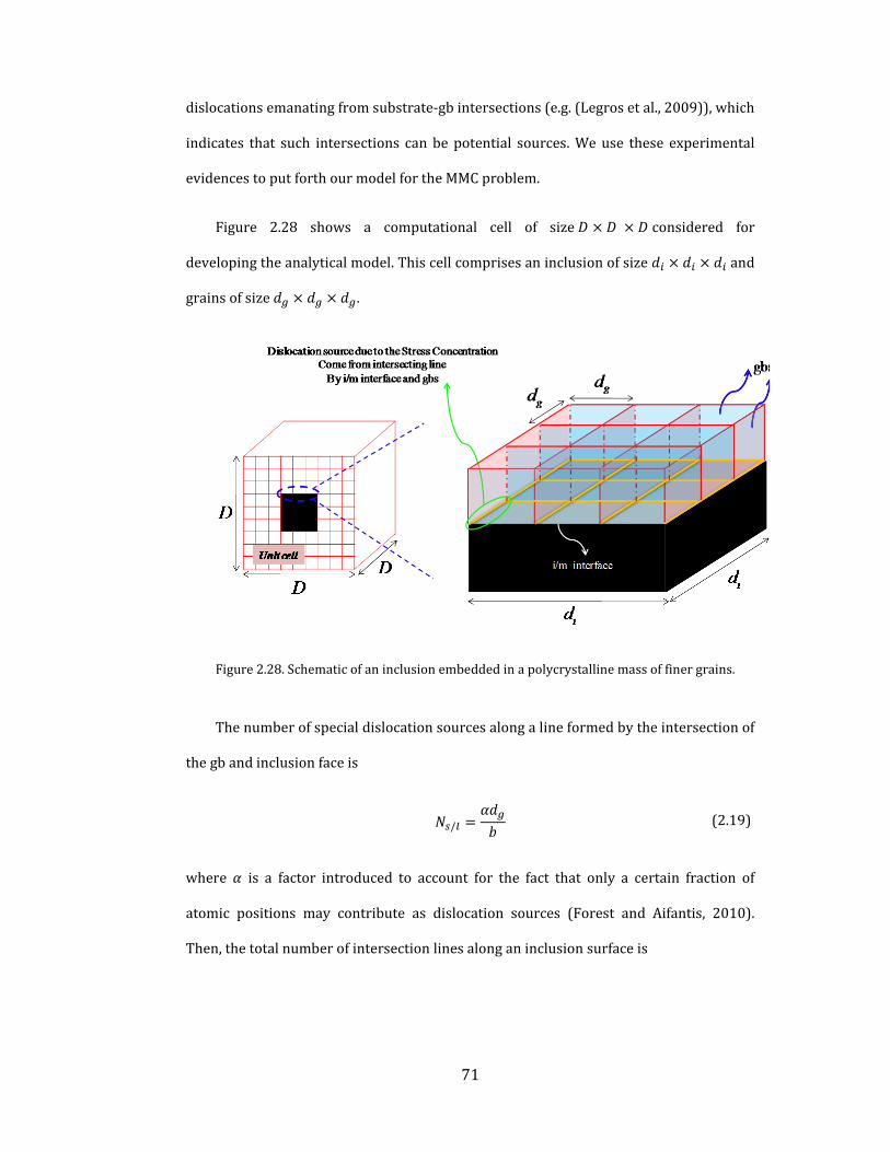
71
dislocationsemanatingfromsubstrate‐gbintersections(e.g.(Legrosetal.,2009)),which
indicates that such intersections canbepotential sources.Weuse these experimental
evidencestoputforthourmodelfortheMMCproblem.
Figure 2.28 shows a computational cell of size considered for
developingtheanalyticalmodel.Thiscellcomprisesaninclusionofsize and
grainsofsize .
Figure 2.28.Schematicof aninclusionembeddedinapolycrystallinemassoffinergrains.
Thenumberofspecialdislocationsourcesalongalineformedbytheintersectionof
thegbandinclusionfaceis
/ ( 2.19)
where is a factor introduced to account for the fact that only a certain fraction of
atomic positions may contribute as dislocation sources (Forest and Aifantis, 2010).
Then,thetotalnumberofintersectionlinesalonganinclusionsurfaceis

72
( 2.20)
where is a geometrical factor that depending on the dimensionality of the problem
and cross‐sectional shape of the inclusion. From Eqs. ( 2.19) and ( 2.20) the number
densityofdislocationsourcesmaybewrittenas
/ ∙ ⁄ ∙ ⁄ ( 2.21)
where is a representative volume (Figure 2.28). Noting that for a given
RVE, ⁄ ,weobtain
( 2.22)
Equation ( 2.22) indicates that the dislocation source density depends linearly on the
inclusion v.f. and inversely on the inclusion and grain sizes. We propose that an
additionaldislocationdensity emanatesfromthesesourcesandcanbequantifiedas
/
( 2.23)
where is the average length of the nucleated dislocations and is the total
number of the dislocation which is nucleated from one source. The plastic strain
accommodatedbythese dislocationsmaybewrittenas(vonBlanckenhagenet
al.,2004)
/
( 2.24)
FromEq.( 2.19),wemaywrite .Assumingthat canbeexpressedas
afractionofthetotalplasticstrain ,thedislocationsemanatedfromeachsourceis

73
( 2.25)
where is a ratio of the total plastic strain to . Substituting Eq. ( 2.25) into Eq.
( 2.24)weobtain
( 2.26)
PuttingEq.( 2.22)inEq.( 2.27)andusingTaylorhardeningmodel,wewrite
∆| | .
( 2.27)
where √3 and .ThroughEq.( 2.27),theinteractioneffectexhibitsa
Hall‐Petch type relation with both the grain size and the inclusion size. Figure 2.29
shows theΔ versus relationship obtained from all the FE simulations
performed in this work for different combinations. Notably, with appropriate
parameters (Table 2‐4) the trend from Eq. ( 2.27) corroborates well with the FE
simulation result, indicating the precise nature of the interaction effect. Thus, in the
analytical modeling of MMCs with size effects, one may account for the grain size‐
inclusionsizeinteractionthroughEq.( 2.27).

74
Figure 2.29.Variationoftheinteractionstrengtheningwiththeproduct .
Therefore,atmoderatestrains,theoverallMMCflowstrengthremainsindependent
ofthegrainsizeanddependsonlyontheinclusionsizeforthe cases,butshows
a strong coupling between them for the cases. The transition from an
uncoupled to a coupled (interaction effect) behavior occurs at . Our detailed
simulations enable isolating this interaction effect as a function of the two
microstructuralfeatures.
Table 2‐4.MicrostructuralsizecombinationsforMMCsimulationsParameter Value Unit
Taylorfactor( 0.3 ‐
Shearmodulusofmatrix( 27 10
Burgersvector( ) 0.25
Strainfactor( ~ 5 10 ‐
Simulation results
Analytical solution (Eq. 15)
0
2
4
6
8
10
0 5 10 15 20 25 30
(
int/
Y )
100
di.d
g (m2)
Simulation results
Equation 15Equation 2.27
75
2.5 Summary and Outlook
Inthischapter,wedevelopedan in‐houseUMATforABAQUS/STANDARD®finite
element code that implements the MSGCP theory to investigate the length‐scale
dependentresponsesofMMCarchitecturesunderthermalandmechanicalloading.
We investigated the role of inclusion size and shape using unit cell model
comprising a single inclusion embedded inside a single crystalmatrix. The simulation
results showed the length‐scale dependent asymmetric responses under monotonic
tensionand compression loading,which are related to theprior thermalGNDdensity
due to thermo‐elastic mismatch at the i‐m interfaces. The pre‐existing thermal GND
densitywasshowntoenhancetheoverallMMChardeningbehaviorinbothtensileand
compressivemechanical loading; however, the increase in hardening is higher in the
caseoftension.
Systematic computational simulations on bare polycrystalline and MMC
architectures were performed in order to isolate the contributions due to grain size,
inclusion size and the interaction thereof. We showed that at moderate strains, the
overallMMCflowstrengthremainsindependentofthegrainsizeanddependsonlyon
theinclusionsizeforthe cases,butexhibitsastrongcouplingbetweenthemfor
the cases. The transition from an uncoupled to a coupled (interaction effect)
behavioroccursat .Basedonthenotionofenhanceddislocationsourcedensity,
weproposedaphenomenologicalmodel thatquantifies their relationship as adouble
Hall‐Petchtypebehavior.Suchaninteractiontermcouldbeincorporatedwithinlength‐
scaledependenthomogenizedapproachestoaccountfortheinteractioneffect.
In this chapter,wemainly focusedon the short‐range interaction as arising from
the thermal and mechanical GNDs. The length‐scale dependent response at yield
observedherewasbecauseofthelength‐scaledependentpriorthermalresidualstress

76
thatwasaccountedforinthesimulations.Inthenextchapter,wediscussanothertype
oflength‐scaledependentinternalresidualstressthatarisesfromthelong‐rangeelastic
interactions between the GNDs. We present a theoretical formulation based on
kinematicincompatibilityandastressfunctionapproachforthislong‐rangeeffectthat
isincorporatedintoacontinuumcrystalplasticityframework.

77
3 Length-scale Dependent Continuum Crystal
Plasticity with Internal Stresses
3.1 Introduction
Conventionalcontinuumplasticity theoriesaresize‐independentandtreat the
plasticbehaviorofcrystallinemetalsasamaterialresponsethatdoesnotdependon
geometric or microstructural length‐scales. However, there are compelling
experimentalevidencesof strengthening innanostructuredmaterials compared to
their coarse‐grained counterparts. Experiments on miniaturized specimens also
suggest that the yield strength ceases to be a purely material parameter as the
specimendimensionsapproachcharacteristicmicrostructurallength‐scalessuchas
grain size, cell‐wall spacing, dislocation spacing etc. At these length‐scales, the
mechanisms of plasticity may be significantly altered giving rise to macroscopic
phenomena such as strong strengthening and modified hardening that are
intimatelytiedtothemicrostructuralandmacrostructuraldetails.Toexplainsome
of the experimentally observed length‐scale effects, traditional continuum
mechanicsofplasticdeformationisaugmentedwithavarietyofmechanismssuchas
strain gradients (Fleck and Hutchinson, 1993), dislocation starvation, limited
dislocation sources (Dehm, 2009; Uchic et al., 2009) and so on. In practice, such
effectsmayoperate intandemandmaycontributesynergisticallyorcompetewith
eachother toproduceoverallplastic responses.Of thedifferentmechanism‐based
length‐scaledependentplasticitytheories,nonlocalapproachesincorporatingstrain
gradients have gained popularity. Such approaches invoke the existence of excess
dislocations which are commonly referred to as the Geometrically Necessary
Dislocations (GNDs), (Nye, 1953) and are necessary to maintain geometric
78
compatibilityduringplasticdeformation.Thereareseveralversionsofthegradient
plasticitytheoriesavailableinliterature,butthecoreconceptistheassumptionthat
thelocalkinematicsandkineticsofdeformationatacontinuumpointaremodulated
byitssurroundingpoints.Theintroductionofagradienttermintroducesalength‐
scaleintotheconventionalplasticityandendowsitwithanabilitytopredictlength‐
scale dependent plastic behavior. In thiswork,we formulate a nonlocal approach
basedoncontinuumdislocationtheorythataugmentstheclassicalcrystalplasticity
theory with length‐scale dependent internal residual stresses. First, we briefly
summarize some of the strain gradient plasticity theories with reference to their
salientfeaturesincorporatingfirstandhighergradientsofstrain.
Fleck andHutchinson (1993) introduced higher‐order stresses corresponding
to the first gradient of plastic strain in the classical plasticity theory tomodel the
length‐scale dependent responses in micro‐beam bending, torsion of micro‐wires
and micro‐indentation. Gao and co‐workers (Gao, 2001; Nix and Gao, 1998)
providedaphysicalbasis for themicrostructural length‐scale in theirMechanism‐
Based Strain Gradient (MSG) plasticity theory that was based on the Taylor
hardening model. Han and co‐workers (Han et al., 2005a, b) extended the MSG
theory to crystal plasticity. These approaches, requiring higher‐order boundary
conditions, have been further refined to include thermodynamically consistent
descriptionsofthedislocationdensity(e.g.(AbuAl‐Rubetal.,2007)).Ontheother
hand, lower order theories (Acharya and Bassani, 2000; Huang et al., 2004; Shu,
2001)avoidthecomplicatingfeaturesofthehigher‐ordertheoriesbyneglectingthe
higher‐order stresses in thegoverningequations.Recently,EvansandHutchinson,
(2009) compared the lower‐order andhigher‐ordergradient theories and showed
that even in the case of first‐gradient theories the nature of the length‐scale
dependentformulationmayexhibiteitherstrengtheningatyieldoranenhancement
inhardeningafteryield.

79
Recent approaches basedon second gradients of plastic strains formulate the
length‐scale dependent plasticity in a thermodynamically consistent manner
(Bardella, 2006, 2008; Gurtin, 2000, 2002; Gurtin et al., 2007) ascribing their
presence to the distribution of defects. These approaches predict enhanced
strengthening, hardening and the internal stress (aka back‐stress) induced
asymmetryinthetension‐compressioncyclicresponse(theBauschingereffect)asa
function of microstructural parameters. Acharya and Roy (2006) developed a
phenomenologicalmesoscopic fielddislocationmechanicsapproach(PMFDM) that
accountsforGNDsindissipativeandenergeticaspectsbasedonincompatibleelastic
distortions.Ertürk, etal.,(2009);Evers,etal., (2004);GerkenandDawson, (2008),
andKurodaandTvergaard(2008a,b)developedphysicallybased,crystalplasticity
theoriesinthattheback‐stressthatdeterminestheeffective(i.e.appliedstressplus
thesize‐dependentbackstress)shearstressforplasticsliponaslipplaneisderived
usingtheVolteradislocation theory.Concurrently,Yefimov,etal., (2004b)derived
similarexpressionsfortheeffectiveshearstressonaslipplanecorrespondingtothe
edge dislocation density using a statistical‐mechanics approach. These different
approaches provide a similar computational construct and may be interpreted in
termsofeachother(KurodaandTvergaard,2006).
Inthischapter,weformulateastressfunctionbasedapproachtoderivelength‐
scale dependent three‐dimensional (3D) internal residual stress tensor arise from
long range interaction among GNDS in the non‐homogeneous spatial GND
distribution density using continuum dislocation theory. Invoking the Beltrami
stress function tensor Sadd, (2005), we systematically relate the length‐scale
dependent internal residual stress tensor ∗to thegradientof theNyedislocation
densitytensor viatheconstitutiveequationsforabulk,linearelasticsolid.This3D
internalstresstensorthatautomaticallyincludestheeffectsofbothedgeandscrew
GNDs is described in terms of the incompatible parts of the continuumkinematic

80
variables,namelytheelasticstrainandcurvaturetensors.Thedefinitionof ∗via
ensures its equilibrium and can naturally blend into the conventional equilibrium
equation. The higher order derivatives of the Green function in ∗decay rapidly
withdistanceintroducingalength‐scalethathastoberelatedtothemicrostructural
detailsofaboundaryvalueproblem(bvp).Thislength‐scaledependentcontinuum
frameworkisthenextendedtothecrystalplasticitytheoryusingthekinematicsand
kinetics of crystallographic slip, expressed in a thermodynamically consistent
manner(Gurtin,2002;KurodaandTvergaard,2008b).
Weconsidertwobvpinvolvingsinglecrystalsunderplanestrainconditionwith
symmetric double slip, namely, (i) a tapered specimen under uniaxial loading
(ignoring the free surface effects), and (ii) constrained simple shear of a single
lamellawithimpenetrableboundaries,fromalayeredmicrostructurethatmimicsa
nano‐twinnedgrain.The importanceof thesize‐dependenthardeningmechanisms
ishighlightedthroughtheseexamples.Theresultsarediscussedwithinthecontext
oftheexperimental/computationalinvestigationsreportedintheliteratureonthe
length‐scaledependentsinglecrystalplasticityundermonotonicandcyclicloading.
3.2 Background
As an illustration to distinguish between the length‐scale dependent
mechanisms due to the GND density, we consider two examples of crystalline
lattices subjected to curvatures. Here, we do not account for the free surfaces by
implicitlyassumingthatthecrystallatticeisembeddedinanelasticregionofsame
elasticproperties(Mesarovicetal.,2010).Figure 3.1ashowsthesurroundingregion
ofacontinuumpointwhereinthecrystal latticeisunderpurebendingresulting in
constant lattice curvature (Fleck and Hutchinson, 1993). Noting the continuum
description of GND used by Gurtin and coworkers (Cermellia and Gurtin, 2000;

81
Gurtin, 2002) andGao and coworkers (Han et al., 2005a;Nix andGao, 1998) (see
appendix A) the non‐uniform strain along the axis results in a non‐zero GND
density component that is proportional to the curvature (Nye, 1953)5.
However,atanysectionalongthe directionthecurvatureisaconstant and
therefore,theGNDdensitycomponentisalsohomogeneouslydistributedalongthe
axes.Consequently,at anycontinuumpoint theaveragestress fieldsdue to the
presence of the GNDs cancel out. In this problem, the size‐dependent hardening
mechanismisrelatedtothepresenceofGNDdensityandcorrespondingshortrange
interactionbetweenSSGsandGNDswhichisthedissipativehardeningmechanism
and corresponds to the first gradient of plastic strain (e. g.(Acharya and Bassani,
2000;NixandGao,1998)).
However, in thesecondcase(Figure 3.1b) the latticecurvaturevaries linearly
alongthe directionandcorrespondingly,theGNDdensityalsovarieslinearly(i.e.
,where and areconstants characterizedby theappliedstimulus
andmaterialcompliance).Asdemonstratedlater,thisleadstotwocontributionsto
hardening, one purely due to the presence of the GND density similar to the first
illustration(shortrangedislocationinteraction)andanadditionaltermduetoanet
internal stress that exists owing to its non‐homogeneous distribution, as their
averagestressfieldsatacontinuumpointmaynotcancelout(longrangeinteraction
among GNDs). The resulting hardening is sometimes referred to as energetic
hardening. Therefore, this internal residual stress due to the non‐zero gradient of
theGNDdensityaswellasdissipativehardeningmechanismmustbeaccountedfor
topredictboththesize‐dependenthardeningmechanisms.
5BasedoncontinuumdescriptionofGNDdensitybyNye(1953),non‐uniformstrainalong
the axisresultsinanon‐zeroGNDdensitycomponent .
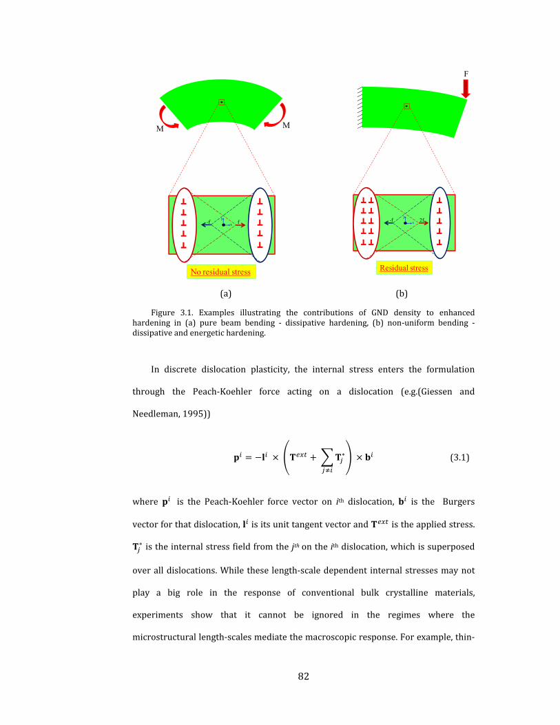
82
(a) (b)
Figure 3.1. Examples illustrating the contributions of GND density to enhancedhardening in (a) pure beam bending ‐ dissipative hardening, (b) non‐uniform bending ‐dissipativeandenergetichardening.
In discrete dislocation plasticity, the internal stress enters the formulation
through the Peach‐Koehler force acting on a dislocation (e.g.(Giessen and
Needleman,1995))
∗ ( 3.1)
where is the Peach‐Koehler force vector on ith dislocation, is the Burgers
vectorforthatdislocation, isitsunittangentvectorand istheappliedstress.
∗istheinternalstressfieldfromthe jthontheithdislocation,whichissuperposed
overalldislocations.While these length‐scaledependent internalstressesmaynot
play a big role in the response of conventional bulk crystalline materials,
experiments show that it cannot be ignored in the regimes where the
microstructurallength‐scalesmediatethemacroscopicresponse.Forexample,thin‐
f-f
No residual stress
MM
x
y
Residual stress
F
2f-fx
y

83
film tension and cyclic bending experiments by Xiang and Vlassak, (2006) exhibit
length‐scale mechanics of strengthening and the Bauschinger effect in passivated
specimenscomparedtotheunpassivatedones.Inthiscasethepassivationlayersact
ashardboundariesthatobstructdislocationsescapingthroughthesurfaces,leading
to the accumulation of dislocations necessary to accommodate geometric
incompatibilities. Very recently,Kiener, et al., (2010) experimentally observed the
BauschingereffectinsinglecrystalCumicro‐beamsundercantileverbending.Even
undernominallyhomogeneous loadingconditionssuchasuniaxialcompressionor
tension the strain and curvature gradients may be induced in miniaturized
specimensbyvirtueofgeometricimperfectionsorfabricationdefectsthatmayplay
vitalrolesinthestrengtheningandhardeningofsinglecrystalspecimens(El‐Awady
etal.,2009a;El‐Awadyetal.,2009b;Fricketal.,2008).
Unlikethediscretedislocationmodelingwherethesuperpositionofthestress
fieldsduetoindividualdislocationsproducesaninherentlynonlocaltheory(Giessen
andNeedleman,1995),inhomogenizedapproachesthatsmearoutthediscreteness
ofdislocationswemustadoptalength‐scaledependentapproachtoaccountforthe
internalstressesduetodislocationarrangement(Figure 3.2).
Figure 3.2. Schematic illustrating the non‐locality arising from the presence of GNDdensityatacontinuumpointandthedistributionoftheGNDdensityaroundthatpoint.
Continuum scale
Dislocation
Micro-scale
Net GND
Integration area
G
G
G
GbLG
G
G
G G
G
bl
G
G

84
3.3 Kinematics of Compatible and Incompatible
Deformations
Incontinuummechanicsthedeformationgradienttensor is
( 3.2)
where is the total displacement gradient tensor.Under small deformation
and small strain assumptions, the total displacement gradient tensor may be
additivelydecomposedintotheelasticandplasticparts
( 3.3)6
Further,wehave
( 3.4)
where istheinfinitesimalstraintensorand istheinfinitesimalrotationtensor.
Further, we assume additive decomposition of the elastic and plastic strains into
theircompatibleandincompatibleparts7
( 3.5)
6Incrystalplasticity,whichwelaterrelateto, ∑ ⊗ where isthe
plasticsliponslipsystem comprisingslipdirection andslipnormal .7Recently,Mesarovicetal.(2010)establishedtheproofthatforanystrainfield,there
existsauniqueorthogonaldecompositionintocompatibleandincompatiblestrainfields.

85
and, ( 3.6)8
Theincompatiblepartoftheelasticstraintensor maybeobtainedfromthe
strain compatibility conditions. In the presence of internal defects such as
dislocations the requirement of compatibility of the total strain introduces an
incompatibilitytensor (Kröner,1959)
( 3.7)
where ∙ , ≝ ∙ . InEq. ( 3.7) the incompatibility tensor,obtained
as the secondgradientof the elastic (orplastic) strain tensor, is ameasureof the
deviationof the elastic (or theplastic) strains from their compatible counterparts
duetothepresenceofexcessdislocationsthatresultininternalstressesinaddition
tothoseduetotheappliedloads.
3.3.1 Compatibility of Lattice Curvature:
Under general loading conditions not only will the strains be non‐uniform
(leading to a strain gradient), but the curvatures (i.e. first gradient of strain)may
alsovarybetween twomaterialpoints.Thecorresponding tensor is referred toas
the Nye tensor (Nye, 1953). In what follows, we systematically relate the
incompatibility tensor to the first gradient of the elastic part of the lattice
curvaturetensor.
8Henceforth,thesubscriptsCandIindicatethecompatibleandincompatibleparts,
respectively,ofthekinematicquantities.

86
The total lattice curvature tensor is given as the gradient of the rotation
vector
12 ,
12 , ( 3.8)
Notingthat , 0,weobtain
12 , . , ( 3.9)
Forconvenience,weset . . , .ThenEq.( 3.9)mayberewrittenas
( 3.10)
Again, in the presence of internal defects the total lattice curvature is still
compatible; however, its elastic and plastic parts may individually be
incompatible.Theincompatiblepartof is
( 3.11)9
Thecompatibilityofthetotallatticecurvaturetensorthengives10
( 3.12)
Thecompatiblepartofthecurvaturetensor maybeconsideredastheelastic
lattice curvature due to the externally applied non‐uniform stress, while the
incompatiblepartof thecurvature is theadditional latticecurvatureduetothe
9NotethatEq.( 3.11)maybeequivalentlywrittenintermsoftheincompatibleparts
oftheplasticstrain andcurvature tensors.
10Thecompatibilityconditionforthecurvaturetensoris . Then,
⇒ .

87
atomicmisfitinthepresenceofGNDs.Further, maybeconceptuallydecomposed
intotheirplastic andelastic parts.Theplasticpartisthelatticecurvature
arising due to the presence of GND density (Nye, 1953) while the incompatible
elasticcurvaturetensor istheadditionallatticecurvaturethatcorrespondstothe
internal residual stress field due to the surrounding excess dislocation density.
Thesedifferentpartsofthetotallatticecurvaturemaybeexplainedbyresortingto
thetwoillustrationsinsection3.2.Inthepurebendingcase, and represent
theelastic latticecurvatureandadditional latticecurvaturedue to thepresenceof
theGNDdensity, respectively,while the vanishes.However, in thenon‐uniform
curvatureexamplethelatticecurvatureduetotheatomicmisfit includesboththe
elasticandplasticparts.Takingthecurlof ,weobtain
( 3.13)
Equation ( 3.13) establishes that the gradient of the incompatible elastic
curvature tensor is non‐zero if anonlinear strain (or stress) field existsdue to an
inhomogeneousGNDdensitydistributioninagivenregion.
3.3.2 Relation between Incompatible Elastic Strain Tensor and
the GND Density Tensor:
Nye(1953)definedtheGNDdensitytensor whosecomponentsarerelatedto
theplasticpartoftheincompatiblelatticecurvaturetensor(SeeappendixA)
12
( 3.14)
where . Applying the curl operator to Eq. ( 3.14), we
obtain
0

88
( 3.15)
Noting the compatibility conditions for the curvature [see Eq. ( 3.12) and Eq.
( 3.13)], we obtain the relation between the incompatible elastic strain and GND
densitytensors
( 3.16)
Since,therighthandsideofEq.( 3.16)issymmetricwerewritethisequationby
consideringthesymmetricpartofthelefthandsideaswell
( 3.17)
i.e. ,
12 , , ( 3.18)
Summarizing,wehaveestablishedtherelationbetweenthegradientoftheGND
densitytensorandthesecondgradientoftheincompatibleelasticstraintensor[Eq.
( 3.17)]inacontinuumsense.Thisequationiscentraltoderivingtheexpressionsfor
theinternalresidualstresstensor,whichisdiscussedinthenextsection.
3.4 Internal Stress Tensor: Stress Function Approach
In the preceding section,we introduced an incompatible elastic strain tensor
thatisrelatedtotheGNDdensitytensor[Eq.( 3.17)].Correspondingtothisstrain
tensor,weintroduceawork‐conjugateinternalstresstensor ∗viaHooke’slaw
∗ ∶ ( 3.19)
where isthefourth‐orderelasticstiffnesstensorforthebulkmaterial.Then,using
superposition,thetotalstressis

89
∶ ∶ ∶ ∶∗
( 3.20)
InvertingEq.( 3.19)werewriteEq.( 3.17)as
∗,
12 , , ( 3.21)
where isthefourth‐ordercompliancetensor.
IntroduceasymmetricBeltramistressfunctiontensor (Sadd,2005)tosolve
Eq.( 3.21),suchthat
∗, ( 3.22)11
FromEqs.( 3.7)and( 3.22)
∶ ( 3.23)
Foranisotropicmedium, dependsonlyontheshearmodulus andPoisson’s
ratio .Then,Eq.( 3.23)simplifiesto(Kröner,1959)
( 3.24)
where 12 1 2
( 3.25)
A fully three‐dimensional solution of Eq. ( 3.24) for an infinite medium is
obtainedusingGreen’sfunction (Kröner,1959)
| | ′3 ( 3.26)
11Eq. ( 3.22)satisfiesstressequilibriumequationbecause ∙ 0

90
| |
| |
8 ( 3.27)
where is theGreen function thatdependson thedimensionalityof theproblem
andtheelasticstiffnessofthematerial(i.e.isotropicoranisotropic).Substituting
fromEq.( 3.17),componentsof are
12
| | ,′3
12
| | ,′3
( 3.28)
UsingtheGreen‐Gausstheoremandsettingthesurfacetermatinfinityequalto
zero,Eq.( 3.28)canberewrittenintheform
12
| | ,′3
12
| | ,′3
( 3.29)
Weassumeappropriateboundaryconditions (Groma,2003;Mesarovic,2005)
whensolvingthebvp’ssothatthesurfaceeffectsduetoimagedislocationfieldsmay
beneglected.
InvertingEq.( 3.25)andsubstituteitinEq.( 3.22),weobtain
∗ 21
∗ 2 , 1 ,
( 3.30)
where
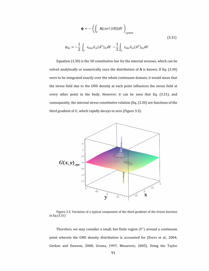
91
12 ,
12 ,
( 3.31)
Equation( 3.30)isthe3Dconstitutivelawfortheinternalstresses,whichcanbe
solvedanalyticallyornumericallyoncethedistributionofA isknown.IfEq.( 3.30)
weretobeintegratedexactlyoverthewholecontinuumdomain,itwouldmeanthat
the stress field due to theGNDdensity at each point influences the stress field at
every other point in the body. However, it can be seen that Eq. ( 3.31), and
consequently,theinternalstressconstitutiverelation(Eq.( 3.30)arefunctionsofthe
thirdgradientof ,whichrapidlydecaystozero(Figure 3.3).
Figure 3.3.VariationofatypicalcomponentofthethirdgradientoftheGreenfunctioninEq( 3.31)
Therefore,wemayconsiderasmall,butfiniteregion aroundacontinuum
point wherein the GND density distribution is accounted for (Evers et al., 2004;
Gerken and Dawson, 2008; Groma, 1997; Mesarovic, 2005). Using the Taylor

92
expansionof aroundthepointr in theregion ′andassuming thatonly the
firstgradientofthisseriesisimportant(Groma,2003),weobtain
,12 , ∙ | | ,
12 , ∙ | | ,
( 3.32)
Theonlyparameterwhichremainstobechosenisthe integrationvolume, ,
whichdefinesa length scale in theproblem that givesnonlocal ∗(Eq.3.32).Note
that ∗doesnotdependon atacontinuumpoint,butonlyon itsgradient.Using
the crystallographic definition of ∑ ⊗ , the resolved
components of ∗on a slip system are obtained as the Laplacian of the plastic
slip .Foraslipsystem thecontributionsfromotherslipsystemstoitsinternal
stressautomaticallyenterstheformulation.
3.4.1 Internal Stress under Plane Strain Condition: Isotropic
Elasticity
Althoughtheresultobtainedintheprecedingsectiongivesa3Dinternalstress
tensor[Eq.( 3.31)]weexplicitlywriteitscomponentsforthesimplercaseofplane
strain. Assuming a plane strain condition in the ‐direction, the only non‐zero
components of the GND density tensor (i.e. containing dislocation lines in the z‐
direction)are , , .Then,thenon‐zerocomponentsofincompatibilitytensor
are[seeEq.( 3.17)]
, , ;
12 , ;
12 ,
( 3.33)

93
FromEq.( 3.22)thein‐planestressescanbeobtainedfromthestressfunction
tensor
∗ , ; ∗, ; ∗
, ( 3.34)
where issimilartoanAirystressfunction.Theout‐of‐planestressesare
∗, – , ; ∗
, , ( 3.35)
Equation ( 3.24) can be solved inwhich 1 /2 and then, the
internalstresscomponentsare
∗ 21 , . , , . ,
, . , , . ,
∗ 21 , . , , . ,
, . , , . ,
∗ 21 , . , , . ,
, . , , . ,
( 3.36a‐c)
where is the integration area that defines a length‐scale. For the plane strain
conditiontheappropriateGreenfunctionis(Kröner,1959)
| |
8ln | | ( 3.37)

94
choosingasquareregion astheintegrationarea,weobtain
∗ 21
0.068 , 0.25 ,
∗ 21
0.25 , 0.068 ,
∗ 21
0.068 , 0.068 ,
( 3.38a‐d)
where ∗ , ∗ , ∗ ∗ are the internal stress components due to edge
dislocations,whilethoseduetothescrewcomponents ∗ ∗ arezero.When
described in terms of the crystal plasticity framework the resolved internal shear
stress ∗ due to Eqs. ( 3.38 a‐d) on slip system is ∗ ∙ ∗ . These
internal stresses bear close resemblance with those derived in the recent works
(Geers et al., 2007; Gerken and Dawson, 2008; Yefimov et al., 2004b). Note that
gradientsinthedislocationdensitiesmayprevailinsinglecrystalspecimensdueto
a variety of reasons including geometric imperfections (Uchic et al., 2009), small
misorientations, fabrication‐induced defects (El‐Awady et al., 2009b)etc. In
polycrystallinematerials,changesincrystalorientationsacrossgrainboundariesor
twinboundariesmayalso setup regionswithhighGNDdensitygradients in their
vicinity.WehighlightsomeoftheseaspectsthroughtheexamplesintheResultsand
Discussionsection.
Thelength‐scaleinthistheoryismathematicallynecessary,butitmustalsobe
physicallymeaningful.Recently,Mesarovicetal (2010)showed thata length‐scale
emergesfromthethermodynamiccoarseningerroroftheenergiescorrespondingto
thecontinuousandsemi‐discreterepresentationsofstackedpile‐ups,whichisofthe
orderofaverageslipplanespacing ~100 foreachslipsystem.Dependingonthe

95
specific problem, microstructural length‐scales may be related to, for example,
averagespacingofobstaclestodislocationmotion inthe formofgrainboundaries
(polycrystals), second‐phase particles (heterogeneous alloys and composites),
dislocationandcell‐wallarrangements(singlecrystals). Inotherwordsthe length‐
scale has to be determined by the microstructural details and may be problem‐
dependent.One interpretationof the length‐scaleemerges fromthecomparisonof
Eqs.( 3.38a‐d)withthatofYefimov,etal.(2004)andrelatestotheaveragespacing
ofdislocations,i.e. ~ (alsosee,Groma,etal.,2003andBayleyetal,2006).With
thisinterpretationtheinternallength‐scalemayrangebetweenfewtensofnm(very
high dislocation density, e.g. Dao, et al., 2006; Lu, et al., 2009) to a few (low
dislocationdensity,e.g.miniaturizedsinglecrystals)andthelength‐scaleitselfmay
evolve with deformation. In the next section, we briefly discuss the extension of
currentstressfunctionapproachtoaccountforelasticanisotropy.
3.4.2 Internal Stress with Elastic Anisotropy
In section 3.4, we derived the internal residual stress using Beltrami stress
functionforanelasticallyisotropicmaterial.Here,theextensionforanisotropiccase
ispresentedbasedonpreviousworkbyKröner,(1955).Fortheanisotropiccasethe
incompatibilityequationiswrittenas(compareEq.( 3.24))
( 3.39)
where is fourth‐order stress function tensor and is a scalar sixth‐order
differentialoperatorwhichisgivenby
∙ ∙ ( 3.40)

96
InEq.(3.40) ∙ , isasecondordertensoroperatorwith asthe
elasticconstant.TheGreenfunctionsolutionofequation(3.39)isgivenby(compare
Eq.( 3.26))
| | ( 3.41)
where is the appropriate Green function for the anisotropic case. For cubic
symmetry,theGreenfunctionis(Burger,1939;Kröner,1953)
| | ∙ | | , /96 ( 3.42)
FurtherstudiesfortheanisotropiccasescanbefoundintheworksofLeutzand
Bauer,(1976)andSteedsandWillis(1979).Then,theinternalstress ∗isgivenby
Eq.( 3.22)wheretherelationbetweenBeltramistressfunctiontensor andfourth‐
orderstressfunctiontensor isdefinedusingasecond‐orderdifferentialoperator
as
( 3.43)
Theexplicitformulationfor operatorforcubicsymmetrymediahasbeen
derivedbyKröner,(1955)andextendedtofullyanisotropiccasebyMichelitschand
Wunderlin(1996).
3.5 Thermodynamically Consistent Visco-plastic
Constitutive Law
Inthissection,wederivetheequilibriumandconstitutiveequationsforcrystal
plasticity including the internal stress using the purelymechanical version of the
thermodynamiclaws.

97
3.5.1 First law of thermodynamics: Power Balance
Givenavirtualdisplacementfield ,thevirtualexternalpowerofanysub‐body
ofvolume boundedbysurface is
∙ ∙ ( 3.44)
where isthetractionvectoronaplanewhoseunitnormalis andand isthe
bodyforcevector.Thevirtual internalpower inthe includingthe internalresidual
stressis
∗ ∙ ( 3.45)
Foranyvirtualdisplacementfield, the internalandexternalpowersshouldbe
balanced,sothat
∙ ∙ ∗ ∙ ( 3.46)
Usingthedivergencetheorem,weobtain
∗ ∙ ∗ ∙
0
( 3.47)
Sincethisequationshouldbevalidforallsub‐body andanyarbitraryvirtual
displacement ,thenonlocaltractionconditionis
∗ ( 3.48)
and,thenonlocalforcebalanceis
∗ 0 ( 3.49)
NotethatfromEq.( 3.22), ∗isalwaysequaltozero.Then,Eq.( 3.49)yields
the classical force balance equation. Writing the plastic part of the total virtual

98
displacement gradient vector in terms of the crystal plasticity framework, in the
absenceofanymacroscopicmotion,wehave
⨂ ( 3.50)
andtheprincipleofvirtualpower[seeEq.( 3.46)]yields
∗ ∗ ∙
∗ ∙ ∙
( 3.51)
where isthetotalshearstressonslipsystem .UsingEq.( 3.50),weobtain
∗ 0 ( 3.52)12
∗ ∗ ∙ ( 3.53)
where ∙ is the resolved shear stress due to external loads and
∗ isthemicroscopictractionvector.
3.5.2 Second law of thermodynamics: Power imbalance
To derive the constitutive equation in the presence of the internal residual
stress, we rewrite the second law of thermodynamics within the framework of
crystalplasticity.Theclassicalformofsecondlawforisothermalconditionis
12Equation( 3.52)isthesameasthemicro‐forcebalanceequationofGurtin(2002)
where ∗ where isthemicro‐stressvector.Inthepresentapproachtheinternal
stressiswork‐conjugatetotheincompatibleelasticstraintensor,akintoGurtin’sdefect
stress(Gurtin,2002)thatwork‐conjugateswiththeGNDdensitytensor.
99
∶ 0 ( 3.54)
where isthefreeenergy.Notingtheorthogonaldecompositionofthetotalstrain
tensor(Mesarovic,etal.,2010),thetotalfreeenergymaybedecomposedas
( 3.55)
where isthestandardelasticstrainenergycorrespondingtothecompatiblepart
of the elastic strain tensor and is the defect energy that corresponds to the
incompatiblepartoftheelasticstraintensor.SubstitutingEq.( 3.55)inEq.( 3.54)we
obtain
∙ ∗ ∙ ∗ 0 ( 3.56)
Thisinequalityshouldholdforallchoicesof , and ;thelinearityofthis
inequality in and respectively provides the sufficient conditions for
macroscopicandmicroscopicenergeticconstitutiveequations
( 3.57)
∗ ( 3.58)
andfromtheinequality,weobtain
∗ 0 ( 3.59)
A visco‐plastic constitutive law satisfying the inequality in Eq. (3.56) can be
writtenas
∗∗ ( 3.60)
where isthetotalcrystallographicslipresistanceduetotheSSDdensityandthe
presenceoftheGNDdensity(Hanetal.,2005a).Writingthetotalinternalpowerand

100
comparing with the theory of Gurtin, et al. (Gurtin et al., 2007) we identify the
energeticanddissipativehardeningterms
:
∗:
∗ ( 3.61)
The first term in Eq. ( 3.61) represents the length‐scale independent stress
power (reversible stored power) associated with externally applied loads. The
second term is referred to as the length‐scale dependent energetic power
(irreversiblestoredpower)as it isassociatedwiththe internalresidualstressand
incompatible elastic strain that will tend to reorganize the GND density from an
energetically efficient configuration. The third term in Eq. ( 3.61) is the plastic
dissipation due to the SSD (length‐scale independent) and GND (length‐scale
dependent)densities.
Table )3‐1)‐)3‐3) summarize key expressions developed in the present
approach. Note that the internal stress tensor is blended into the continuum
frameworkthroughordinaryequationsofforcebalanceandtractioncondition,and
additionalgoverningequationsarenotrequired.
Table 3‐1.Summaryofgoverningequations
Straindecomposition
Kinematicrelation ,12 , ,
Localforcebalance 0
Non‐localforcebalance ∗ 0

101
Table 3‐2.Summaryofconstitutiveequations
Localelasticconstitutivelaw
∶
Nonlocalinternalstressconstitutivelaw
∗ ∶ 2 , 1 ,
Nonlocalvisco‐plasticconstitutivelaw
∗
∗
Table 3‐3.Summaryofunknownvariablesandavailableequations
Unknownparameters #unknowns Governingequations #equations 6 ∗ 0 3 6 ∗ ∶ 6 6 , ∗, … 6 3 6∗ 6 ∗ ∗ , … 6
Total# 27 Total# 27
3.6 Results and Discussion
Inthissection,weinvestigatetwoproblemsinvolvingsinglecrystalspecimens
usingthenonlocalvisco‐plasticconstitutiverelation(Eq.( 3.60)).Forsimplicitywe
consideratwo‐dimensionalplanestrainsetupwithcrystalsorientedforsymmetric
doubleslipwithrespecttotheloadingdirection.
3.6.1 Tapered Single Crystal Specimen Subjected to Uniaxial
Loading
Figure 3.4showsa taperedsinglecrystalof lengthL inplanestraincondition
that is constrainedagainst slipatoneendandsubjected to anaxial force at the

102
otherend.Thecrystal isassumedtodeformundersymmetricdoubleslip.Theslip
systemsareorientedatanangle giving
sin , cos , 0 , cos , sin , 0 , sin , cos , 0 , cos , sin , 0
Figure 3.4. A tapered bar under uniaxial loading. Dashed tapered edges indicate thattheyaresufficientlyawayfromthecenterlineofthespecimen
Althoughthisgeometryismotivatedbytherecentmicro‐pillarexperimentson
single crystals, there are important differences that are discussed briefly before
proceedingwiththesolution.First,theactualproblemisessentially3D,whereaswe
assumeaplanestraincondition.Further,asmentionedearlier,thepresentapproach
does not account for free surfaces thatmay give rise to image stresses and cause
othermechanismsofstrengthening.Tocircumvent thecomplexityassociatedwith
thefreesurfaceeffects,weimplicitlyassumeaquasi‐1Dsituationinthatthetapered
boundariesareconsideredtobesufficientlyawayfromthecrystalcenterandtheir

103
presenceisaccountedforonlythroughthestressvariationalongitslengthfroman
appliedforce13.
We apply a uniaxial force F at the top and assume that at the base of the
specimen 0 , 0 (specifically, zero, in this example) and
γα 0 0sothatthedislocationsarefreetomoveintothebase,akintoamicro‐
pillar.Theonlynon‐vanishingstresscomponentisthen ⁄ ,where
is thewidthofthecrystalatsection thatchanges linearlyfrom at the loaded
edge to at the constrained edge. Then, the resolved shear stress on each slip
system is sin cos and the corresponding plastic slip is
.Withtheplasticstraintensor ∑ ⊗ theplastic
slipgradientis 0, , , 0 .InthecrystallographictermstheGNDdensitytensor
is ∑ ⊗ ;therefore,weobtain
0 0 00 0 0
2 , 0 0
wherec andsdenotecos andsin , respectively.For thisproblemtheonlynon‐
zeroGNDdensitycomponentistheonewiththeBurgersvectorinthe direction
andthedislocationlineinthe direction.Forthetotalsliphardeningweadoptthe
SSDandGNDdependenthardeningoftheform(Hanetal.,2005b)
13Alternatively,onemayassumethatthetaperededgesarecoated(i.e.nofreesurface
forthedislocationtoexitthespecimen)withasufficientlythickmaterialofelasticproperties
sameasthatofthecrystalsothattheydonotpileupalongthoseedges.Theseareobviously
highlyidealizedassumptions,butenableustoconsiderasimplersystemtoprovidesemi‐
analyticalsolutions.

104
1 | | ,
/
( 3.62)
Thenon‐zerocomponentsoftheinternalstresstensor[seeEq.( 3.38a‐d)]are
∗1
∙ ,
∗ 0.271
∙ ,
∗ ∗ ∗
∗ 0
( 3.63)
andthecorrespondingresolvedinternalresidualshearstressoneachslipsystemis
∗ ∗, , ( 3.64)
where.
. Substituting Eqs. ( 3.62) and ( 3.64) into Eq. ( 3.60) and integrating
withrespecttotime,weobtain
,
1 | | ,
( 3.65)
Equation ( 3.65) is solved using the fourth‐order Runge‐Kutta method. The
material and geometric parameters used are 0.01, 5⁄ , 1000 ,
45°, 0.2 , 0.4 , 10. The results for monotonic and cyclic
loadingarediscussednext.
a.Monotonicloading:
To begin with, we investigate the influence of by setting 0. Figure 3.5
showsthevariationofthemagnitudeofplasticslipalongthelengthofthespecimen
fordifferentratios.Asexpected,themagnitudeoftheplasticslipdecreases
withdecreasing ,thatisforasmallerspecimensizeorlarger .

105
Figure 3.5. Plastic slip along bar axis y for various ratio of / for taperedspecimenundermonotonictension
With decreasing the internal stress term inEq. ( 3.65) becomes increasingly
dominant and provides a strong resistance to plastic slip. The increasing internal
stresswithdecreasing tendstohomogenizetheplasticslipasobservedfromthe
trendoftheplasticslipvariationwithdecreasing .
Next, we highlight the relative influence of the two length‐scale dependent
dissipativehardeningmechanisms,i.e.thedissipativehardeningduetothepresence
of GND (corresponding to ) and the one due to GND density gradient
(correspondingto )ontheoverallresponseofthecrystal.Figures 3.6aandbshow
the normalized resolved shear stress on a slip system versus the magnitude of
plasticslipat fordifferentvaluesof and ratios.Figure 3.6ashows
that the length‐scaledependentdissipativehardeningdue to thepresenceofGND
influencesthepost‐yieldresponse,whichhasbeenpreviouslyreportedbyHan,etal.
(2005b)inthecontextofMSG‐CPtheory.

106
(a)
(b)
Figure 3.6. Resolved shear stress versus plastic slip at for tapered bar undermonotonictensionforvariousratios(a) ⁄ ,and(b) ⁄ .
However, this enhanced hardening effect is discernable onlywhen the slip is
appreciably large,well beyond the initial yield. In comparison, Figure 3.6b shows
thattheinternalstresssignificantlyinfluencesboththeresponseatincipientslipas
well as at relatively larger slip. That is, the length‐scale dependence due to the
gradientoftheGNDdensityhasastrongerinfluenceonboththestrengtheningand
0 0.005 0.01 0.015 0.02
1.6
1.5
1.4
1.3
1.2
1.1
1.0
0.9
0.8
0.7
g
L
l
β = 1000β = 10β = 2β = 1β = 0.5
0g
Decreasing β
0 0.005 0.01 0.015 0.02
b
L
l
0g
1.6
1.5
1.4
1.3
1.2
1.1
1.0
0.9
0.8
0.7
η= 1000η = 100η = 50η = 25η = 15η =10
Decreasing η

107
hardeningbehaviorofa crystal compared to that arising from thepresenceof the
GNDdensity.Thisisfurtherexacerbatedgiventhattherangeof ratiosconsidered
here is relatively small compared to the range of ratios. Figure 3.7 signifies the
influenceofgeometric imperfectiononthedistributionofthe internalstressalong
thespecimenlength.Thelargerthe initialtaperthemorenon‐homogeneousisthe
GND density distribution that causes higher resolved internal shear stresses on
individual slip systems. Consequently, the plastic slip on the slip systems would
becomehardergivinganoverallplasticallystrongerresponse.
The strong strengthening and hardening observed in this example is
qualitatively similar to the specimen length‐scale dependent strengthening
behaviors reported in some of the recent experiments on miniaturized single
crystals(e.g.(Fricketal.,2008))thatindicatepresenceoftheGNDdensity.Whilethe
actual mechanisms of strengthening in such miniaturized experiments have not
beenfullyunraveled,theresultsfromthepresentworkcorrelatequalitativelywith
the experimentally observed size‐dependent plasticity in the presence of strong
gradients(Maaßetal.,2009).
Figure 3.7. Distribution of normalized internal shear stress ∗ along the tapered
specimenundermonotonictensionfor(a) 2.86°,(b) 5.71°. 50.
AlthoughinthepresentcasethegradientintheGNDdensityisduetospecimen
taper,presenceoffillets,lowangleboundaries(Uchicetal.,2009)orsurfacedamage
layersdue to fabricationmayalsoproducesignificantgradientsat small specimen

108
sizes(El‐Awadyetal.,2009b).Thus,thenon‐gradientbasedsize‐effects(e.g.source‐
limiteddislocationplasticity,dislocationstarvation)postulatedinsuchexperiments
may be augmented by those due the internal stresses arising from the non‐
homogeneousdistributionoftheGNDdensity.
b.Cyclicloading:
Wenowinvestigatetheresponseofthetaperedsinglecrystalspecimenundera
singletension‐compressioncycle.Manymetalsexhibitthewell‐knownBauschinger
effectunder cyclic loading. In thepresentwork, the internal stress tensorderived
from the inhomogeneous GND density distribution produces a size‐dependent
Bauschingereffect.Forsimplicity,wesuppressthecontributionfromthedissipative
hardeningbysetting 0.
(a) (b)
Figure 3.8.Resolvedshearstressversusplasticslipat fortaperedbarundercyclicloading(a) 100,(b) 50.
Figure 3.8 shows the resolved shear stress versus plastic slip curves at
plotted for two different values of . We also include the response of the same
specimens under monotonic loading. For fixed the monotonic compressive
responseismuchstrongerthanifthespecimenwereloadedunderasingletension‐
Cyclic loading
Monotonic compression
Cyclic loading
Monotonic compression
0g
0 0.01 0.02 0.03 0.04 0.050 0.01 0.02 0.03 0.04 0.05
1
0.5
0
-0.5
-1
1
0.5
0
-0.5
-1
0g

109
compression cycle. The disparity between the monotonic and cyclic responses
increases with decreasing giving a length‐scale dependent Bauschinger effect
(Kiener et al., 2010; XiangandVlassak, 2006).However,upon reverse loading the
directionoftheresolvedshearstressduetoexternal loadreverses,butthatofthe
internal stress does not as the GND arrangement is unaffected. This causes the
specimentoyieldatasmallerloadinthereverseloading.Thehardeningbehavioris
alsoweaker in the reverse loading compared to the initial forward response. In a
realistic scenario with more than two slip systems, one may observe stronger
hardening due to latent hardening that may accentuate the Bauschinger effect
(Bayley et al., 2006). Figure 3.9 shows that geometric imperfections strongly
influence the Bauschinger effect and it increases with increasing degree of
imperfection.Suchanasymmetricresponsecannotbepredictedsolelybya theory
thatdoesnotaccountfortheeffectofdistributionofthedislocationdensity.Thisis
true irrespective of the particular nature of the strain gradient theory (Xiang and
Vlassak,2006).
(a) (b)
Figure 3.9. Resolved shear stress versus plastic slip at y=L for various tapered angleundercyclicloading( =100)(a) 2.86°,(b) 5.71°.

110
3.6.2 Single Crystal Lamella Subjected to Simple Shear
In the previous problem, the internal stress appeared because of non‐
homogeneous distribution of the stress due to geometric imperfections. Here, we
considerthe internalstress inaspecimenwithnogeometricnon‐uniformities,but
due to the pile‐up of dislocations at impenetrable boundaries. Consider a layered
crystal as shown in Figure 3.10. We isolate a single layer from this crystal and
assumeittobeasemi‐infinitelamellaofthickness2 withsymmetricdoubleplanar
slipsubjected tosimpleshear.Thisgeometry is reflectiveofa typical twin lamella
withinagrainofanano‐twinnedpolycrystal(Lietal.,2010).
Figure 3.10.Asinglelamellawithinanano‐twinnedcrystalundersimpleshear.
Weconsiderhardboundaryconditionsonthelamellaboundariessuchthat
0 0, 2 0; 1,2 ( 3.66)
These conditions ensure that noplastic slip occurs along a slip system at the
boundaries causingdislocations to pileup there. Theonlynon‐zero componentof
macroscopicstress in thisproblemis .Thecorrespondingresolvedshearstress
111
andplasticslipduetotheexternalloadare,respectively, cos 2
and ,where istheorientationoftheslipsystemswithrespecttothe
loading direction. The plastic slip gradient is 0, , , 0 and the continuum
dislocationdensitytensor forthiscaseis
0 0 00 0 00 2 , 0
FromEq.( 3.38a‐d)andusingSchmidlaw,theresolvedinternalshearstresson
eachslipsystemis
∗ ∗ ∗0.1361 , cos 2 ( 3.67)
andthecorrespondingplasticslipis
0.1361 , 2
1 | | ,
( 3.68)
The material parameters are the same as in the previous example, except ,
whichissetequalto90°providingthehighestplasticincompatibility.Figure 3.11a
showsthenormalizedshearstress‐averageplasticslipresponsefordifferent .
Asexpected,strongstrengtheningoccurswithdecreasing .Figure 3.11bshowsthe
normalizedshearstressat 0.002asafunctionofnormalizedlamellathickness.
It is interesting to note that for the range of values shown in the figure the
strengtheningtrendcompareswellwithHall‐Petchbehavior.
For a given applied stress, Eq. ( 3.68) plastic slip variation along the lamella
thicknesscanbeobtained,subjecttotheboundaryconditionsinEq.( 3.66).Forfixed
appliedloading( 1.5 ),Figures 3.12aandbrespectivelyshowthevariationof
plasticslipandnormalizedinternalresolvedshearstressonaslipsystemalongthe

112
normalizedthicknessordinatefordifferentvaluesof .Asshowninfigures3.12,for
fixed (i.e.samematerial),whenthelamellathicknessismuchlargercomparedto
the internal length‐scale ≫ 1 , only a very narrow region is affected by the
boundaryandawayfromittheeffectdecaysrapidly.
(a)
(b)
Figure 3.11.(a)Normalizedresolvedshearstress ⁄ versusaverageplasticslipasafunctionof for 90°, (b)Normalized resolvedshear stress ⁄ versusnormalizedlamellathicknessat 0.2%.
0
0.5
1
1.5
2
2.5
3
3.5
4
0 0.005 0.01 0.015 0.02 0.025 0.03 0.035 0.04 0.045 0.05
η = 1
η =1.3
η = 2
η = 3.3
η = 5
η = 10
η = 20
0g
avg
0.5
1
1.5
2
2.5
0 1 2 3 4 5 6
0g
0.5
0
1.73bg l
2 0.92R
bl
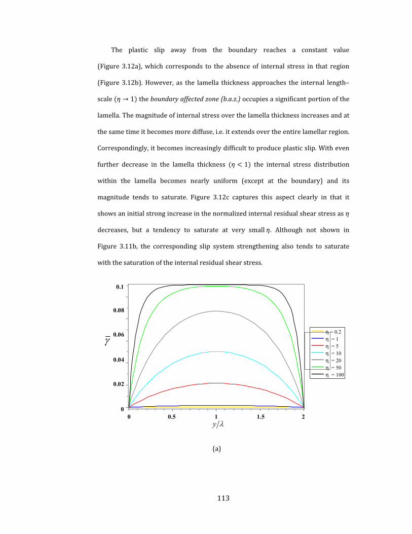
113
The plastic slip away from the boundary reaches a constant value
(Figure 3.12a),which corresponds to the absence of internal stress in that region
(Figure 3.12b).However, as the lamella thickness approaches the internal length–
scale → 1 theboundaryaffectedzone(b.a.z.)occupiesasignificantportionofthe
lamella.Themagnitudeofinternalstressoverthelamellathicknessincreasesandat
thesametimeitbecomesmorediffuse,i.e.itextendsovertheentirelamellarregion.
Correspondingly,itbecomesincreasinglydifficulttoproduceplasticslip.Witheven
further decrease in the lamella thickness 1 the internal stress distribution
within the lamella becomes nearly uniform (except at the boundary) and its
magnitude tends to saturate. Figure 3.12c captures this aspect clearly in that it
showsaninitialstrongincreaseinthenormalizedinternalresidualshearstressas
decreases, but a tendency to saturate at very small . Although not shown in
Figure 3.11b, the corresponding slip system strengthening also tends to saturate
withthesaturationoftheinternalresidualshearstress.
(a)
0 0.5 1 1.5 2y
0.1
0.08
0.06
0.04
0.02
0
η = 0.2η = 1η = 5η = 10η = 20η = 50η = 100
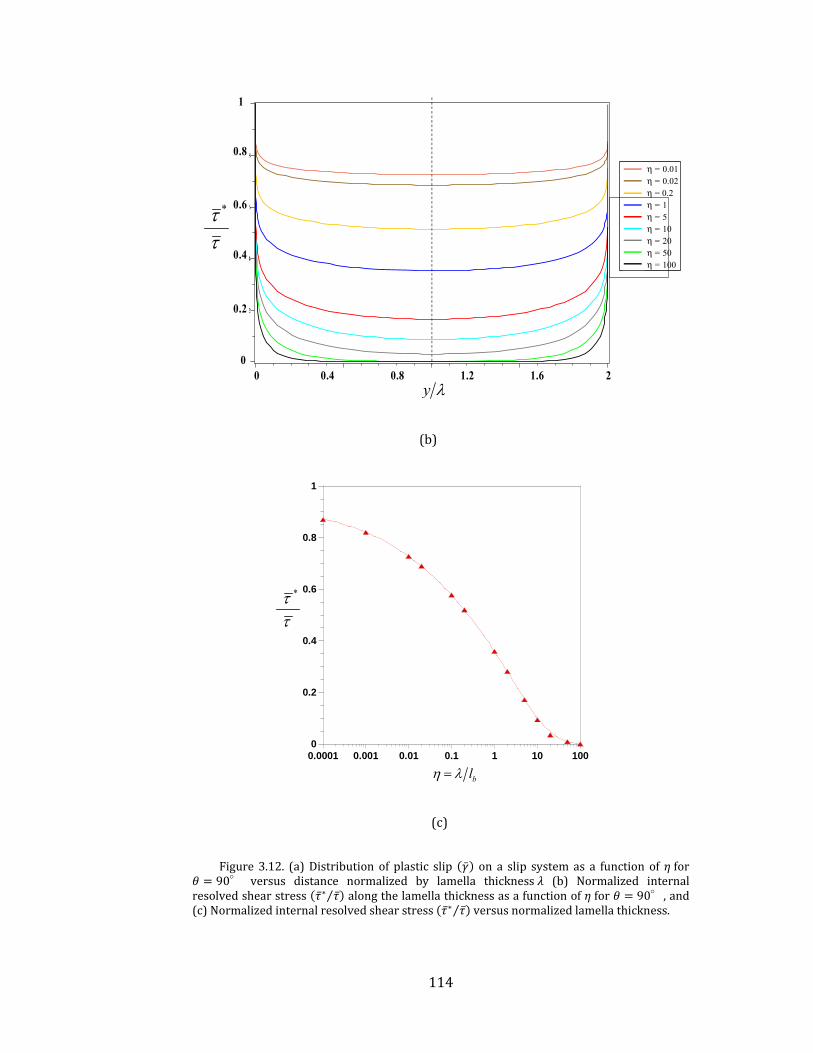
114
(b)
(c)
Figure 3.12. (a)Distribution of plastic slip on a slip systemas a function of for90° versus distance normalized by lamella thickness (b) Normalized internal
resolvedshearstress ∗ ⁄ alongthelamellathicknessasafunctionof for 90°,and(c)Normalizedinternalresolvedshearstress ∗ ⁄ versusnormalizedlamellathickness.
η = 0.01η = 0.02η = 0.2η = 1η = 5η = 10η = 20η = 50η = 100
2
4
6
8
y 0 0.4 0.8 1.2 1.6 2
*
1
0.8
0.6
0.4
0.2
0
bl
*
0
0.2
0.4
0.6
0.8
1
0.0001 0.001 0.01 0.1 1 10 100
115
3.7 Summary
Inthischapter,wedevelopedanonlocalcrystalplasticityapproachenrichedby
internal residual stresses that arise due to the non‐homogeneous distribution of
GND densities. The salient feature of this work is the analytical derivation of the
length‐scaledependent3Dinternalstresstensorusingthestressfunctionapproach.
This second order internal stress tensor blends into the conventional equilibrium
equationsandboundaryconditions.Inthecrystalplasticityframework,theinternal
stressesappearasadditionalresolvedshearstressesoneachslipsystemalongside
those due to the externally applied loads. The visco‐plastic constitutive law for
crystallographic slip that includes this effect is presented in a thermodynamically
consistent manner. The connections between the continuum and crystallographic
variablesinthisformulationrenderitusefulforthedevelopmentofcomputational
frameworkforthe deformationtheoryaswellassmallstraincrystalplasticity
theory.
Theanalytical exampleshighlight the importanceof the internal stresson the
size‐dependent strengthening and hardening in single crystals. Geometric
imperfections can cause strong gradients in the GND density and lead to a
strengtheningof theoverallstress‐strainresponse inspecimensthataresubjected
tonominallyuniaxialmacroscopic loads.Asevident from the secondexample, the
internal stress‐induced strengthening of a slip system is akin to the Hall‐Petch
behavior,buttendstosaturateatsmallmicrostructuralsizes.
Asaclosure,webrieflycomparethepresentapproachwithsomeoftheexisting
nonlocaltheoriesthatincorporatetheinternalresidualstresses.Thekeyequations
derived here for internal stresses results bear close resemblance with the
pioneering efforts of Groma and co‐workers that use a statistical approach

116
mimicking the collective behavior of dislocations (Groma, 2003; Groma andBakó,
1998;Zaiseretal.,2001).RecentversionsofthisapproachbyYefimovetal(2004)
have been developed for edge dislocations. The approach of Gerken and Dawson
(2008)againrestrictsitsfocusontheinternalstressesduetoedgedislocations.In
theirtheory,theaverageinternalstressfieldsderivedfromVolterradislocationsare
simplified assuming a bilinear variation of the GND density, but the motivation
behind this choice is not obvious. Recently, Ertürk, et al (2009) presented a
sophisticatedcrystalplasticityapproachwithbackstressesaccountingforthelatent
hardening effects due to both screw and edge GNDs. In comparison to these
approaches, the present approach is based on a continuum theory of kinematic
coarseningandalsoincludescontributionsfromedgeandscrewcomponentsofthe
GNDs. Theprojection of the gradient of theGNDdensity tensoron to a given slip
system leads to the contribution from other slip systems providing a latent
hardening effect. Further, it should be possible to extend this approach to
anisotropicelasticcasesusingappropriatestressfunctions(Seesection3.4.2).This
aspectseemsnotwell‐outlinedinmosttheoriesinthatthedevelopmentisrestricted
toelasticallyisotropiccases.
OurfocusinthischapterwasoninteractionofGNDsininfinitemediumwhere
GNDinteractionwithboundariessuchasfreesurfacesandinterfacesareneglected.
It showed that internal stresses only present when GNDs are distributed non‐
uniformlyandGNDdensitygradientpresent.Inthenextchapter,wewillaccountfor
GNDs‐boundaries interaction inthe finiteregion. Itshowsthateven inpresenceof
uniform GND density distribution, internal stresses arise due to GND‐boundary
interactionswhichaffectoverallbehaviorofsmallscalestructures.
117
4 A Crystal Plasticity Analysis of Length-scale
Dependent Internal Stresses with Image
Effects
4.1 Introduction
Internal stresses arise in crystalline metals due to ensembles of geometrically
necessarydislocations(GNDs)thataccommodatelatticeincompatibilities.Animportant
macroscopic consequence of these internal stresses is that they produce length‐scale
dependentstrengtheningunder forwardloadingandkinematichardeningundercyclic
loading with decreasing microstructural and/ or specimen sizes (Kiener et al., 2010;
Motzetal.,2005).Theseinternalstressesappearbecauseofthelong‐rangedislocation‐
dislocation and dislocation‐boundary interactions. Of particular interest are the long‐
rangeGND‐GNDandGND‐freesurfaceinteractions.Whilemoleculardynamics(MD)and
discretedislocationdynamics(DDD)accountfortheseinternalstressesasalength‐scale
dependententity(e.g.Fiveletal.1996;Yanetal.2004),coarserrealizationsbasedon
continuum approaches, e.g. crystal plasticity, rely on augmenting the traditional
kinematics and kineticswith additional length‐scale dependent features. A continuum
crystal plasticity description of the internal stress due to long‐range GND‐GND
interactionappearsasthe firstgradientoftheGNDdensity withrespecttoaslip
direction (Evers et al., 2004; Gerken and Dawson, 2008; Gurtin, 2002; Kuroda and
Tvergaard, 2008b). A natural requirement of this result is that the GND density
shouldbespatiallynon‐uniform.Indeedinmanycases, variesalongslipdirection
due to a variety of situations including geometric non‐uniformity (see chapter 3), or
deformationmappingleadingtogradients,e.g.simpleshear,(Eversetal.,2004;Gurtin
etal.,2007;Yefimovetal.,2004b).However,incaseswhere doesnotvaryspatially
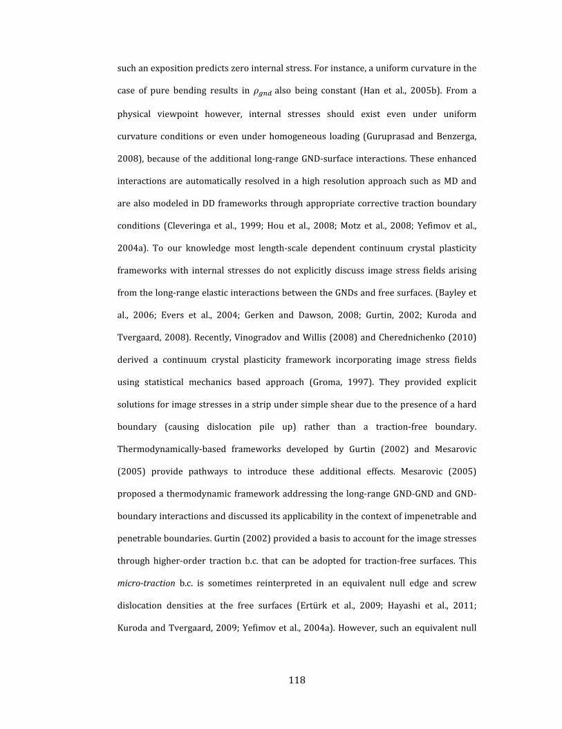
118
suchanexpositionpredictszerointernalstress.Forinstance,auniformcurvatureinthe
case of pure bending results in also being constant (Han et al., 2005b). From a
physical viewpoint however, internal stresses should exist even under uniform
curvature conditionsor evenunderhomogeneous loading (Guruprasad andBenzerga,
2008),becauseof theadditional long‐rangeGND‐surface interactions.Theseenhanced
interactions are automatically resolved in ahigh resolution approach suchasMDand
arealsomodeledinDD frameworksthroughappropriatecorrectivetractionboundary
conditions (Cleveringa et al., 1999; Hou et al., 2008;Motz et al., 2008; Yefimov et al.,
2004a). To our knowledge most length‐scale dependent continuum crystal plasticity
frameworkswith internal stresses donot explicitly discuss image stress fields arising
fromthelong‐rangeelasticinteractionsbetweentheGNDsandfreesurfaces.(Bayleyet
al., 2006; Evers et al., 2004; Gerken and Dawson, 2008; Gurtin, 2002; Kuroda and
Tvergaard,2008).Recently,VinogradovandWillis(2008)andCherednichenko(2010)
derived a continuum crystal plasticity framework incorporating image stress fields
using statistical mechanics based approach (Groma, 1997). They provided explicit
solutionsforimagestressesinastripundersimpleshearduetothepresenceofahard
boundary (causing dislocation pile up) rather than a traction‐free boundary.
Thermodynamically‐based frameworks developed by Gurtin (2002) and Mesarovic
(2005) provide pathways to introduce these additional effects. Mesarovic (2005)
proposedathermodynamicframeworkaddressingthe long‐rangeGND‐GNDandGND‐
boundaryinteractionsanddiscusseditsapplicabilityinthecontextofimpenetrableand
penetrableboundaries.Gurtin(2002)providedabasistoaccountfortheimagestresses
through higher‐order traction b.c. that can be adopted for traction‐free surfaces. This
micro‐traction b.c. is sometimes reinterpreted in an equivalent null edge and screw
dislocation densities at the free surfaces (Ertürk et al., 2009; Hayashi et al., 2011;
KurodaandTvergaard,2009;Yefimovetal.,2004a).However,suchanequivalentnull

119
GNDprescriptionmaynotfullyaccountforthelong‐rangeimageeffectsproducedbya
traction‐freesurface.
SimilartotheDDapproaches(e.g.(Fiveletal.,1996;Lubardaetal.,1993;Vander
Giessen andNeedleman, 1995; Yan et al., 2004)), superposition of image stress fields
due to dislocation ensembles described by a continuum densitymeasure would be a
natural way to satisfy the b.c.’s at free surfaces. There are some classic studies on
obtaining imagestress fieldsarising fromasingledislocationhosted inasemi‐infinite
medium(Jagannadham and Marcinkowski, 1979; Lubarda and Kouris, 1996b), in the
proximityofabi‐materialinterface(Chouetal.,1975;JagannadhamandMarcinkowski,
1980;LubardaandKouris,1996a)andinathinstripwithtwofreesurfaces(Fotuhiand
Fariborz, 2008; Hartmaier et al., 1999; Ting, 2008). (Saada, 2008) provided a brief
reviewontheimagefieldsarisingfromplanardislocationarraysandtheircontribution
to theplasticdeformation. (Khanikaretal.,2011;Lubarda,2006;WeinbergerandCai,
2007)investigatedimageeffectsingeometriesmimickingmicro‐scalespecimens.
Inthischapter,wepresentacoarse‐grainedapproachthataccountsforimagefields
withincontinuumcrystalplasticityarisingfromthelong‐rangeelasticinteraction(LRI)
betweenaGNDdensity field andbounding free surfacesof the specimen thathosts
thisGNDfield.Theapproachexpandsonourpreviouswork(chapter3)byintroducinga
generalized stress function that now incorporates appropriate boundary corrections
through image fields. As a model system, we analyze a thin specimen experiencing
uniformcurvatureundertheactionofanexternalbendingmoment.Theanalysisshows
thateveninthecaseofauniformGNDdensitydistribution,internalstressesoccurfrom
twosources
I. LRIarising from finite spatial extentof theGNDdensity (embedded in an
infinitemedium).
II. LRIbetweentheGNDdensityandfreesurfacesappearingasimagefields.

120
Thestressfunctioncorrespondingto(i)isobtainedviaappropriateinfinitemedium
Green’s function (chapter 3) and the resulting stress fields are akin to the Volterra
solutionasappliedtofinitespatialextentoftheGNDdensityinaninfinitemedium.The
solution to (ii) is incorporated by writing an available stress function for a single
dislocation in a finite medium derived using complex Fourier transform approach
(FotuhiandFariborz,2008),equivalentlyintermsoftheGNDdensity.Theformulation
isappliedtoinvestigatelength‐scaledependentresponsestriggeredbyinternalstresses
–(a)strengtheningundermonotonicpurebendingasafunctionofdecreasingspecimen
thicknessand(b)kinematichardeningundercyclicpurebending.Wealsocompareour
results with experiments and DD simulations and propose a likely origin of variable
internallength‐scaleforinternalstresses.
Inthefollowingsection,wefirstprovidekeyequationspertainingtoourprevious
workbasedonstressfunctions(Chapter3)andthenextendtheapproachbyincluding
additionalstressfunctionsprovidingimagefields.
4.2 Nonlocal Continuum Theory with Internal Stress and
Image Fields
AsdiscussedintheprecedingChapter,thetotalstress comprisesthestressdueto
externallyappliedloads andinternalstress ∗,givenby
∶ ∶ ∶ ∶∗
( 4.1)
where isthetotalelasticstraintensor, isthecompatibleelasticstrainarisingfrom
lattice stretching due to external loading, is the incompatible elastic strain tensor
arisingfrominternalstressduetodistributeddefectsand isthe fourth‐orderelastic
stiffness tensor. Internal stresses arise from the presence of defects that could span
several orders of length‐scales. One of the common sources of these internal residual

121
stresses is the presence of ensembles of excess dislocations (GNDs) and the relevant
resolution is sometimes referred to as amesoscopic continuum (Zaiser and Seeger,
2002). At this length‐scale, it is appropriate to describe GNDs by equivalent density
fieldsthatcouldvaryspatially.Ithasbeenwell‐establishedthattheseinternalstresses
occur due to the long‐range dislocation‐dislocation and dislocation‐interface elastic
interactions(HullandBacon,2001;Mughrabi,1983;ZaiserandSeeger,2002).Aspecial
caseof the latter is thedislocation‐ free surface interaction,which is the focusof this
work.
The incompatible part of elastic strain is given by the incompatibility
condition(chapter3),
( 4.2)
whereN is incompatibility tensor (Kröner, 1959) andA is the GND density tensor14.
Then,fromEq.(4.1)and(4.2)canbewrittenas
∶ ∗ ( 4.3)
A solution to Eq. (4.3) in terms of the internal stresses arising from may be
obtained by introducing a second‐order Beltrami stress function tensor (Kröner,
1959)
∗ 21
( 4.4a)
14TheGNDdensitytensorcanbewrittenas where isplasticdisplacement
gradient(Gurtin,2002).ThenegativeandtransposeofGNDdensitytensor isoftenreferredto
asNye’stensor.(Nye,1953;ArsenlisandPark,1999)

122
where isthesecondorderidentitytensorand isaGreen’sfunction.Thecomponent
formofEq.(4.4)is
∗ 2 , 1 ,
12 ,
12 ,
(4.4b)
The elastic Green’s function G in Eq. (4.4) depends on the dimensionality and
geometryof theproblemandmay includeappropriatetermsaccounting forparticular
boundaryconditions. Kröner (1959)proposeda solutionbasedonaGreen’s function
foranelasticinfinitemedium,whichgivesinternalstressfieldsduetoGNDdensitythat
do not account for image effects. However, in systems with finite boundaries these
internal stresses need a correction in order to properly account for the long range
dislocation‐boundaryinteraction.Itisthislattercorrectiontermedasimagestressthat
isafocusofthiswork.
To incorporate the image stresses due to dislocation‐boundary interaction using
GND density fields, the internal stress tensor in Eq. (4.1) may be conceptually
decomposedas
∗ ( 4.5)
Figure4.1illustratesthisconceptuallyforabodywhoseboundaryisafreesurface.
The full problem (Fig. 4.1a) comprises a body bounded by a finite boundary
subjectedtoexternaltractions .Itisassumedthat hostsasmoothlyvaryingGND
density field where is the position vector. The problem may be conceptually
decomposedintotwoauxiliaryproblems:

123
(i)externalstressfieldsin subjectedto (Fig.4.1b),and
(ii)internalstressfieldsin inthepresenceof (Fig.4.1c).Thisproblemmaybe
further considered to be a superposition of two sub‐problems: (ii‐a) internal stress
field inadislocatedbody embeddedwithinaninfinitemedium thatgivesriseto
a spurious tractions (Fig. 4.1d), and (ii‐b) internal stress fields produced by
application of equal and opposite tractions at the boundary to eliminate (Fig.
4.1e).
Figure 4.1.Decompositionof the internalstressproblemforaspecimenhostingageneralGNDdensitydistribution.Seetextfordiscussion.

124
In accordance with the foregoing decomposition, here is calculated using the
elastic Green’s function in the presence of defects (chapter 3) providing non‐local
stress fields due to GND density in an infinitemedium, while the additional stress
arising from the GND‐boundary interaction needs an appropriate corrective kernel
function .Itisusefultomentionthatwhile isafunctionofonlythespatiallocationof
apointofinterestinthemediumfromthedislocation, isafunctionofboth,thespatial
positionofapointfromthedislocationanditsproximitytothefiniteboundary.Further,
the nature of is expected to depend on the details of the boundary, e.g. a
rigid/deformableinterfaces,freesurfaceandstraightorarbitraryboundaries.Although
aGreen’s functionbasedtreatmentprovidesanelegantapproachtosuchproblems,at
timesitmaybedifficulttoobtainanappropriatekernelfunctionfor ,e.g.anarbitrarily
curvedboundary.However,kernel functionshavebeenderived forsome fundamental
cases accounting for finiteness of domains. Some of the examples involving single
dislocations or dislocation arrays include geometries such as an elastic half‐space
(Head,1953; JagannadhamandMarcinkowski,1978;LeeandDundurs,1973;Lubarda
and Kouris, 1996b; Ma and Lin, 2001) an infinitely long strip with two parallel free
surfaces (Fotuhi and Fariborz, 2008; Moss and Hoover, 1978; Nabarro, 1978) , a
straight, rigid interface separating two dissimilar half‐spaces (Chou et al., 1975;
Jagannadham and Marcinkowski, 1980). These kernel functions aim at providing
fundamental solutions based on discrete dislocations to the problems of image fields,
but may differ based on the conceptual appeal (e.g. image dislocation versus surface
dislocations).Inwritingappropriatecorrectivestressesbasedonacontinuumanalogof
dislocations (i.e.dislocationdensity), it ispossible touse these fundamental solutions.
Themodelproblemdiscussedinthisworkisthatofpurebendingofathinfilm,whichis
represented by a constant GND density tensor and the corrective stress field is
obtained by extending the basic construct developed by Fotuhi and Fariborz (2008)
where the stress function is directly obtained using complex Fourier transformation

125
approach.Althoughthediscussionispresentedindetailforthemodelbendingproblem,
itshouldbepossibletoconstructsimilarsolutionsforotherinterfacesinteractingwith
edgeandscrewGNDdensitiesusingabove‐mentionedfundamentalkernelfunctionsor
similarapproaches(Cherednichenko,2010;VinogradovandWillis,2008).
4.3 Single Crystal Specimen under Plane-Strain Pure
Bending: Role of Free Surfaces
This sectionpresents ananalytical formulation for thenon‐local internal stresses
arisingfromGNDdensitydistributionincludingtheeffectofboundingsurfacesthrough
imagestressfields.Asmentionedintheprecedingsection,thisisachievedbyusingthe
kernel functions derived by Fariborz and Fotuhi (2008) for a single dislocation in a
boundedisotropicmedium(AppendixA).Weillustratetheproblemasfollows:consider
aninfinitedomainofacrystalwithauniformGNDdensityfield .Adiscreteequivalent
of thisproblemisan infiniteregioncontaining infinitely longequallyspacedarraysof
dislocationswithidenticalBurgersvector.Itcanbeshownthatforthisarrangementthe
averagestressfield(integrationofthestressfieldsarisingfromindividualdislocations)
overagivenregionthatdefinesamesoscopiclength‐scaleiszero.Thisisbecauseeach
individualdislocationappears tobeat the centerof theGNDarray and the individual
stressfieldscanceleachotherwhenintegrated(Eq.(4.4)).Ontheotherhand,ifapartof
such a defective (dislocated) region is embedded in a pristine (i.e. dislocation‐free)
material of same or different elastic properties, or is simply removed from the host
material, a net internal stress must exist due to (a) finite spatial extent of the GND
density, and (b) additionalLRIbetween theGNDsand theboundaries. In theextreme
situationoftheregionboundedbyfreesurfaces,suchastructurewouldrepresentathin
film thathasbeen subjected toauniformplastic curvature (Fig. 4.2).The extentover
which the internal stress is felt away from the free boundaries should depend on the

126
internal length‐scale corresponding to the long‐range dislocation stress fields and the
specimendimensions.
Figure 4.2. Schematic showing effective GND arrangement in a specimen under uniformcurvature. The specimen thickness is 2 and the GND density is described by the global, andlocal , coordinates.
Foraplanestrainconditioninthe direction,Eq.(4.5)canbewrittenas(Fotuhi
andFariborz,2008)inthecomponentformas(seeAppendixA)
∗ χ χ χ χ
∗ χ χ χ χ
∗ χ, χ χ χ
( 4.6)
where and arethecomponentsof representingdislocationswithlinelength
inthe directionandBurgersvectoralong and directions,respectively.Theχandχ
are thekernel functions representing the stress fieldsof anedgedislocationwithunit
Burgersvectorinaninfinitemediumanditscorrespondingcorrectionduetotraction‐
free boundaries, respectively (given in Appendix A). In Eq. (4.6), while the field is
translationally invariant, i.e. it does not carry the information about the absolute
2h
2l

127
positionofapointfromthefreesurface, thisunaccountedfeatureis incorporatedinto
theoverallexpressionbythe fieldwhichembedstherelevantspatialinformation.
Without losing the essential features in Eq. (4.6), we consider a thin film with
uniform GND density subjected to external bending moment under plane strain
condition as a model problem. Consider a structure of length 2 ( direction) and
thickness 2 ( direction) with a plane‐strain condition in the z –direction.
Assume that the structure is subjected to pure bending in the plane (Fig. 4.2).
The axis lies at the neutral plane and the coordinate is measured from this
neutral plane. A typical point in the continuum is located at , from the neutral
plane and carries a local coordinate system , with it. Further, the structure is
assumedtobesufficientlylongsothatthe endfaces(i.e.loadedfaces)andtheout‐of‐
plane faces do not contribute to image stress fields. The end faces constitute the
thickness of the structure. Since the structure is under pure bending, the in‐plane
internalshearstress ∗ mustbezeroandonlythenormalcomponentsoftheinternal
stresstensor(Eq.(4.6))exist.Assumingthattheradiusofcurvatureofthestructureis
much larger than its thickness, theGNDdensitycanbeconsideredtobeuniformover
theentirethickness.
NotethatinEq.(4.6)theintegrationisperformedoveranarea,whichimpliesthat
theinternalstressatagivenpoint,say , ,isinfluencedbytheGNDdensitiesand
their stress‐fields in its finite neighborhood. Such a non‐local representation allows
introducinganinternallength‐scale intotheproblem(Eversetal.,2004;Gerkenand
Dawson,2008).This length‐scale isproblem‐dependentandrequiressomediscussion.
Thislength‐scaleisproblem‐dependentandrequiressomediscussion.Wereturntothe
issueof themicroscopicunderpinningsofsuchan internal length‐scale laterwhenwe
compareourresultswithexperiments,butbrieflydiscuss itherewithinthecontextof
thegeometryunderconsideration.If ismuchlargerthan ,theninthepresenceofa

128
uniform GND density the surfaces would influence regions only in its proximity|
| | | | |.15Therefore,inpresenceofuniformdistributionofGNDs, onlyfeltin
athinsurfacelayerwiththicknessof duetothefinitenessofdislocationdistribution.
Similarly significantlyinfluencetheinternalstressinthesurfacelayerduetoimage
effect. Therefore, overall the internal stress variation remain zero away the neutral
plane before becoming non‐zero closer to the surfaces. Note that image field has
small contribution in region| | | |. ). Each component of internal stresses is
depictedinFigure 4.3for 0.2.
Figure 4.3.Internalstresscomponentsvariationacrossthicknessfor 0.2 5 .
15BasedontheDDsimulations,fromadislocation‐surfaceinteractionviewpoint,perhapsit
wouldbemoreappropriatetoassumeadislocation‐freezone(DFZ)ofafixedthicknessinthe
proximityofasurface,irrespectiveofthespecimenthickness(Cleveringaetal,.1999).Suchan
assumptionwouldintroduceanadditionallength‐scaleintotheformulation.However,wedonot
considerthisaspectinthecurrentwork.
-0.2 -0.1 0.0 0.1 0.2-1.0
-0.8
-0.6
-0.4
-0.2
0.0
0.2
0.4
0.6
0.8
1.0
xx
xx
Non-dimensional stress
2h 1
2 3
y
1
2
3

129
Theoverall internalstressvariationacrossbeamthickness isshowninFigure 4.4
fordifferentvalueof . It canbe seen that internal stress decreasewithdecreasing
whichmeans increasingspecimenthicknesswhere isconstant. In thecurrentwork,
the internal stress arises from interaction of GNDs among themselves and with free
surfaceswhichprovide internal stresseseven in caseofuniformdistributionofGNDs.
Justrecently,(Hayashietal.,2011)presentedsimilarinternalstressprofilesinrelatively
thick(comparedtotheirchoseninternallength‐scale)beamsunderpurebending.They
employedahigher‐orderslipgradienttheorythatinducesGNDdensitygradientsowing
toanullGNDdensityb.c.atfreesurfaces.
Figure 4.4. Variation of normalized internal stress along the normalized specimenthickness fordifferentvaluesofnormalizedinternallength‐scale .
However,theydidnotexplicitlyaccountfortheGND‐surfaceLRIthatcauseimage
effects.However,thistheoryaccountforinternalstressarisefromGNDinteractioninan
infinitemediuminpresenceofnon‐uniformGNDdistributionandconsequently image
effectsduetofreesurfacesarenottakenintoaccount.Inaddition,finiteboundariesare
not explicitly considered in this group of higher order theories and so they are not
-0.4 -0.2 0.0 0.2 0.4-1.0
-0.8
-0.6
-0.4
-0.2
0.0
0.2
0.4
0.6
0.8
1.0
L=0.2 L=0.1 L=0.03
(y)
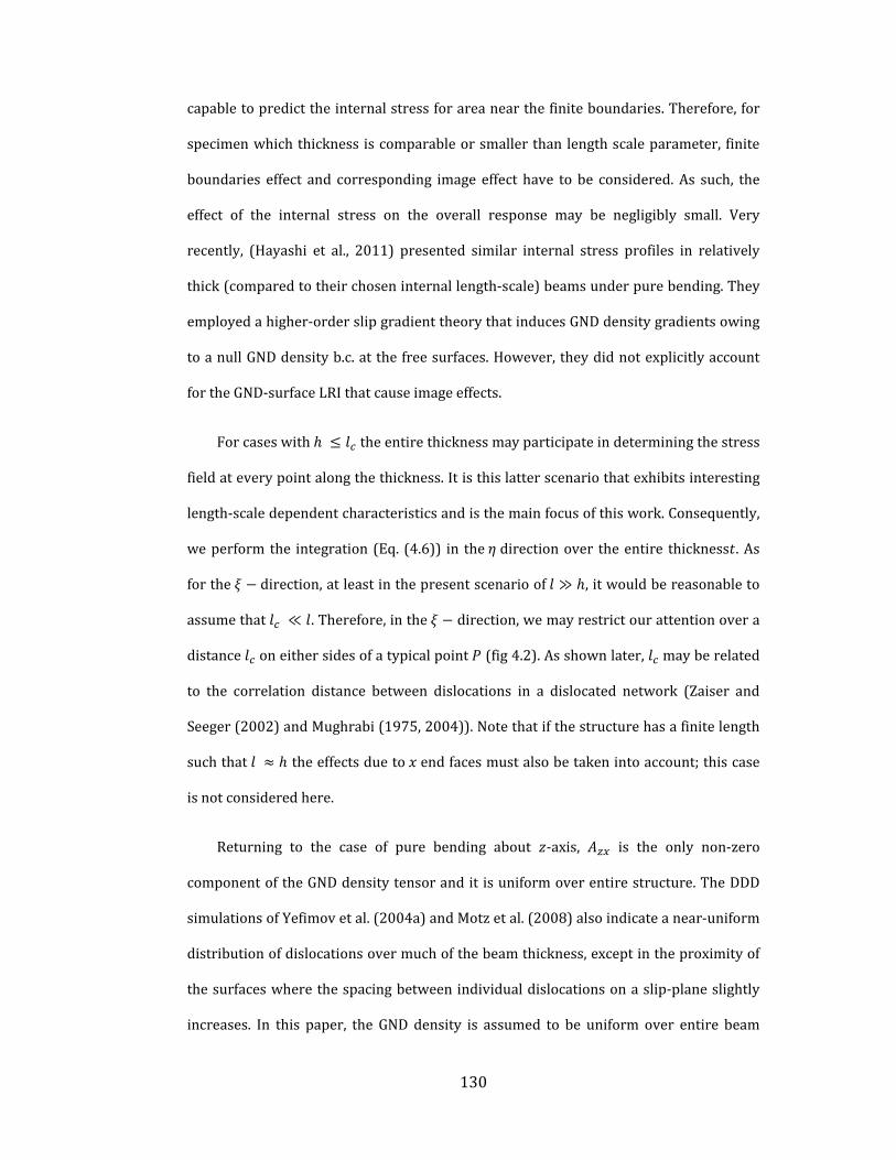
130
capabletopredicttheinternalstressforareanearthefiniteboundaries.Therefore,for
specimenwhichthicknessiscomparableorsmallerthanlengthscaleparameter, finite
boundaries effect and corresponding image effect have to be considered.As such, the
effect of the internal stress on the overall response may be negligibly small. Very
recently, (Hayashi et al., 2011) presented similar internal stress profiles in relatively
thick(comparedtotheirchoseninternallength‐scale)beamsunderpurebending.They
employedahigher‐orderslipgradienttheorythatinducesGNDdensitygradientsowing
toanullGNDdensityb.c.atthefreesurfaces.However,theydidnotexplicitlyaccount
fortheGND‐surfaceLRIthatcauseimageeffects.
Forcaseswith theentirethicknessmayparticipateindeterminingthestress
fieldateverypointalongthethickness.Itisthislatterscenariothatexhibitsinteresting
length‐scaledependentcharacteristicsandisthemainfocusofthiswork.Consequently,
weperformthe integration (Eq. (4.6)) in the directionover theentire thickness .As
forthe direction,atleastinthepresentscenarioof ≫ ,itwouldbereasonableto
assumethat ≪ .Therefore,inthe direction,wemayrestrictourattentionovera
distance oneithersidesofatypicalpoint (fig4.2).Asshownlater, mayberelated
to the correlation distance between dislocations in a dislocated network (Zaiser and
Seeger(2002)andMughrabi(1975,2004)).Notethatifthestructurehasafinitelength
suchthat theeffectsdueto endfacesmustalsobetakenintoaccount;thiscase
isnotconsideredhere.
Returning to the case of pure bending about ‐axis, is the only non‐zero
componentoftheGNDdensitytensoranditisuniformoverentirestructure.TheDDD
simulationsofYefimovetal.(2004a)andMotzetal.(2008)alsoindicateanear‐uniform
distributionofdislocationsovermuchofthebeamthickness,exceptintheproximityof
thesurfaceswherethespacingbetweenindividualdislocationsonaslip‐planeslightly
increases. In this paper, the GND density is assumed to be uniform over entire beam

131
structure. SpecializingEq. (4.6) forpurebending,weobtainafter re‐arrangementand
normalization
∗
∗
( 4.7)
where ⁄ , ⁄ , ⁄ and ⁄ .
Since and are odd functions of (see Appendix A), ∗ vanishes
automatically and consistently satisfies the shear traction boundary condition
at .Asimilarconditionfor ∗ requiresthatitmustalsovanishat .From
Eqs.(4.7b),the and componentsof ∗ are
12 1
, , , , ,
( 4.8)
where and arethenon‐dimensionalstressesthatdependon and ,and isa
non‐dimensional spatial frequency coefficient that appears in the complex Fourier
transform solution of the . stress function (Fotuhi andFariborz, 2008).AppendixA
givesdetailedaccountofthefunctionsinvolvedinEqs.4.8band4.9b.Figure4.5shows
thevariationof and overthebeamthickness.Itcanbeseenthroughtheseplots
thatnotonlydoes ∗ vanishattheboundaries, italsovanishesovertheentirebeam
thickness as the magnitude as the distribution of exactly equal to and opposite
of ,independentof .

132
Therefore,theonlynon‐zerointernalstressis ∗ thatreflectsthecurvaturedueto
the uniform GND density distribution. From Eqs. (4.8), the and components
of ∗ readasfollows
12 1
3
, , , , ,
( 4.9)
InEqs.(4.9)thenon‐zeroGNDdensitycomponent popsoutoftheintegralasit
is independentof thespatialcoordinates for thepresentproblem. Ingeneral, theGND
densitycomponentsshouldberetainedinsidetheintegraliftheyvaryspatially.Inthat
case, the internal stresses would also be induced by smooth spatial GND density
gradients.
Figure 4.5. Variation ofnon‐dimensional stresses in direction ( and ) overbeamthickness for a given normalized internal length‐scale 10 (Eq. 4.8a,b). Note that thecomponentsareequalandoppositeresultinginoverall ∗ 0.
-1.0 -0.5 0.0 0.5 1.0-0.03
-0.02
-0.01
0.00
0.01
0.02
0.03
No
n-d
ime
nsi
ona
l str
ess
Y
sigma yy-im sigma yy-f

133
ItisinformativetonotethatEq.(4.8a)and(4.9a)aretheaveragedsolutionsofthe
Volterra‐based result for a two‐dimensional array of GNDs distributed over 2
embeddedinanelasticallyisotropicmedium.Thus, internalstressexistsinthisregion
that isdelineatedby the finiteextentof theGNDdensity fieldembedded inamedium
(Eq. 4.9a). It is furthermodulated by the image stress fields due to dislocation ‐ free
surfaceinteractionsbytheadditionalterm(Eq.4.9b).Equation(4.9a)canbeintegrated
analyticallyandFig.4.6showsthevariationof with and .Forafixed , varies
nonlinearly with .Specifically, → 0as → 0and asymptotes to a constant value
for ≫ 1.
Figure 4.6.Variationof withYandL.(SeeEq.4.10a)
Ontheotherhand,foragiven , varieslinearlyoverthethicknessandchanges
fromcompressivetotensileabouttheneutralaxisconsistentwiththenotionofbending
stresses.ThislattervariationcompareswellqualitativelyandquantitativelywiththeDD
0
2
4
6
8
10
-3
-2
-1
0
1
2
3
-1.0
-0.5
0.0
0.5
1.
YL

134
simulation results of (Cleveringa et al., 1999) for a single crystal under pure bending,
whichalsoshowsalinearvariationofthebaselinestressfield(i.e.beforecorrectingfor
the image fields) across the beam thickness16. Unlike the calculation, the
variation(Eq.4.9b)overthethicknessrequiresnumericalintegrationandisperformed
using Gauss‐Laguerre quadrature (Press et al., 1992) 17. Appendix B provides the
detailed procedure of the numerical integration and related convergence study. As
showninFig.4.7aandb, variationwith and isqualitativelysimilartothatof .
(a) (b)
Figure 4.7.Variationof respectto(a)YatL=10and(b)LatY=1.(SeeEq.4.10b)
FromEqs.(4.9a,b),theoverallinternalstress ∗ canbewrittenas
∗ ( 4.10)
16Fig7inCleveringa’swork(1999)showsthatthe stressmagnitudelinearlyvariesfrom
0MPa(neutralaxis)to 600MPa forabeamwith 4 and 12 with
27 subjectedtoaplasticrotationof0.013radians.Weobtainthesamevaluesby
substitutingtheseparametersinEq.(4.9a).
17Apartfromthis,inEq.(4.9a,b),thePoisson’sratio cannotbeisolatedfrom .
components.Weset 0.33forallthecalculations.
-1.0 -0.5 0.0 0.5 1.0-3
-2
-1
0
1
2
3
0 5 10 15 200.0
0.5
1.0
1.5
2.0
2.5
3.0

135
where (Fig4.8).Thevalueof asymptotesto~1 3⁄ as ⁄ tends
to infinity, which indicates that the internal stress saturates in the cases where the
specimenthickness ismuchsmallercomparedtotheinternal length‐scale.Notethat
could vary because of changes in , , or both. An important question is: should
change with , and if so, how? In other words, should remain fixed, increase or
decrease with ? If changes linearly with then constant and therefore,
constant(Fig.4.8).Insuchascenario,althoughtheinternalstressisnon‐zeroitisnot
length‐scale dependent. On the other hand, decreasing (increasing) with increasing
(decreasing) indicatesthattheinternalstresswillalsodecrease(increase).Thisisalso
true if constant. Thus, except for the constant case the remaining possibilities
providethetrendexpectedfromalength‐scaledependentinternalstresstheory.Aswe
showlaterinthepaper,comparingthepredictedresultswithexperimentssuggeststhat
thepossibilityof increasingwithdecreasing isaplausiblescenario.
Figure 4.8. Variation of the normalized total internal stress with normalized internallength‐scale atspecimensurface( 1).
0 20 40 60 80 1000.0
0.1
0.2
0.3
0 5 10 15 200
1
2
3
‐

136
Equation (4.10) brings to fore a noteworthy feature in that the length‐scale
dependent internal stress shows an explicit dependence on the magnitude of GND
density.Thisisincontrasttomostcontinuumformulationsforlength‐scaledependent
internal stresses that predict a non‐zero internal stress only if GND density gradient,
ratherthananon‐zeroGNDdensity,ispresent(Eversetal.,2004;GerkenandDawson,
2008; Gurtin, 2002). Thus, the length‐scale dependent internal stressesmay exist not
onlybecauseofanon‐uniformGNDdensitybutalsobecauseoftheimagefieldsandthe
lattermaycauseinternalstressesevenif theGNDdensity isnominallyuniformovera
given finite region. From this viewpoint, the finite spatial extent of a uniform GND
densityfielddelineatedbytwofreesurfacesconsideredinthisworkservesasasimple,
yetinsightfulexampletofurtherprobetheinternalstresscharacteristicsinthepresence
ofimagefields.
Beforediscussing the results of theparticularmodelproblem, it is useful tonote
that the decomposition of the real problem in Fig. 4.1 and the treatment explicitly
presented for the bending problem bears some semblance with the superposition
techniqueusedinDDPapproaches(VanderGiessenandNeedleman(1995))(although
therearesomeimportantdifferences,discussedasfollowing).Usingthisbroadanalogy,
theoveralltraction atafreeboundarywithunitnormal maybewrittenas(Fig.
4.1)
( 4.11)
with beingthemicro‐tractioncorrespondingtotheinfinitemediumsolution(Fig.
4.1d)and beingthecorrectivetractionappliedtoremovethespurioustraction
at the free surfaces arising from fields (Fig. 4.1e). Thus, from a superposition
viewpointthefollowingtractionsb.c.’sconditionsshouldbesatisfied
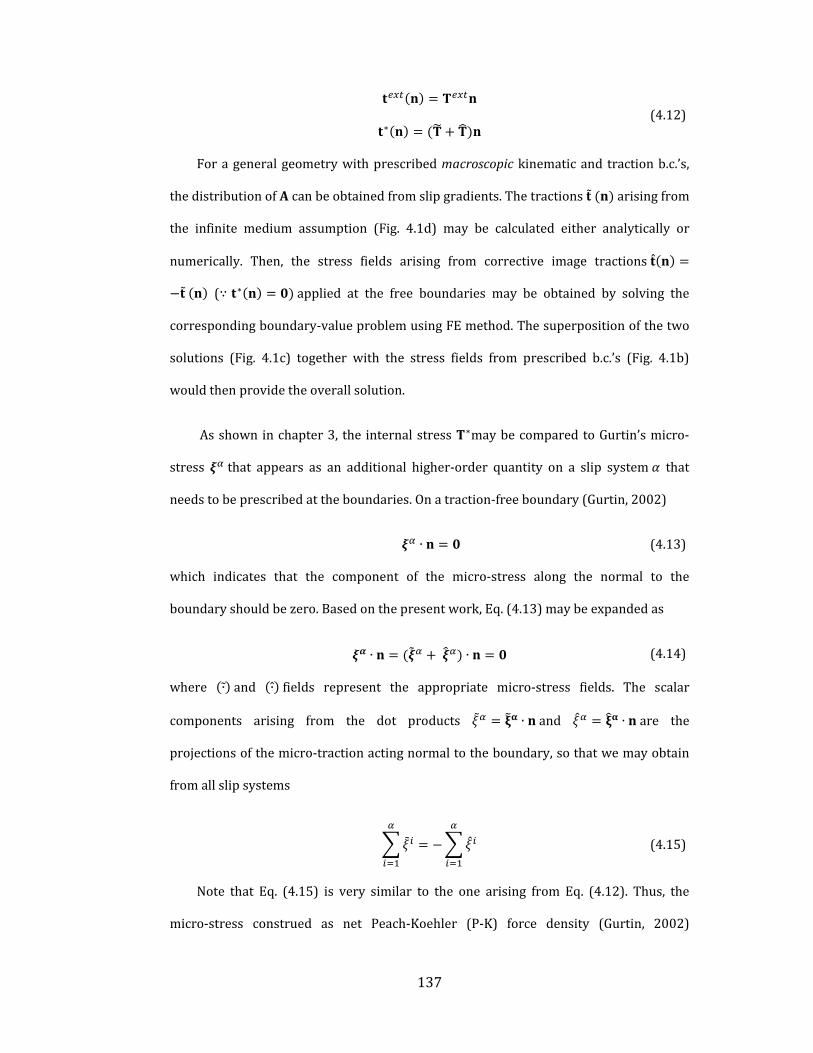
137
∗ ( 4.12)
Forageneralgeometrywithprescribedmacroscopickinematicand tractionb.c.’s,
thedistributionof canbeobtainedfromslipgradients.Thetractions arisingfrom
the infinite medium assumption (Fig. 4.1d) may be calculated either analytically or
numerically. Then, the stress fields arising from corrective image tractions
(∵ ∗ applied at the free boundaries may be obtained by solving the
correspondingboundary‐valueproblemusingFEmethod.Thesuperpositionofthetwo
solutions (Fig. 4.1c) together with the stress fields from prescribed b.c.’s (Fig. 4.1b)
wouldthenprovidetheoverallsolution.
Asshowninchapter3, the internalstress ∗maybecomparedtoGurtin’smicro‐
stress that appears as an additional higher‐order quantity on a slip system that
needstobeprescribedattheboundaries.Onatraction‐freeboundary(Gurtin,2002)
∙ ( 4.13)
which indicates that the component of the micro‐stress along the normal to the
boundaryshouldbezero.Basedonthepresentwork,Eq.(4.13)maybeexpandedas
∙ ∙ ( 4.14)
where ∙ and ∙ fields represent the appropriate micro‐stress fields. The scalar
components arising from the dot products ∙ and ∙ are the
projectionsofthemicro‐tractionactingnormaltotheboundary,sothatwemayobtain
fromallslipsystems
( 4.15)
Note that Eq. (4.15) is very similar to the one arising from Eq. (4.12). Thus, the
micro‐stress construed as net Peach‐Koehler (P‐K) force density (Gurtin, 2002)

138
manifestsas image stress ata traction‐freeboundary.This canalsobeascertainedby
notingthesimilaritybetweentheinternalstressduetoaGNDdensityandtheP‐Kforce
actingonadiscretedislocationinthepresenceofexternaltractions,otherdislocations
andboundaries(Lubarda,2006)
( 4.16)
where isthePeach‐Koehlerforcevectoronithdislocation, istheBurgersvector,
is itsunit tangentvectorand is theappliedstress. is the internalstress tensor
from the jth on the ith dislocation (dislocation‐dislocation interaction) in an infinite
medium and is the image field contribution arising from the dislocation‐boundary
interactionofthe dislocationtotheP‐Kforceonthe dislocation.Inouropinion,
displacement‐based formulationswith slip gradients (orGNDdensities) as degrees of
freedom(e.g.KurodaandTvergaard,2009;Hayashi,etal,2011)donotclearlyconnect
the null GND density with the higher‐order natural b.c.’s at free surfaces. Their
equivalentrepresentationasnullGNDdensityseemstoaccountonlyforthe . termin
Eq. (4.14), because the internal stress expressions are based on infinite medium
assumptionthatdiscountthe . contribution.
Although,theforegoingexpositionisconceptuallyanalogoustoDDPapproaches,it
isusefultonoteatleastafewimportantdifferencesbetweenthetwoapproaches.First,
unlike theDDP approach thatmodels dislocations as discrete elastic singularities, the
presentsetuptreatsthemasacontinuousdensityfield.Consequently,thestressfields
areexpectedtobesmoothcomparedtotheDDPresultsastheysmearoutfluctuations
atafiner‐scale.Second,byvirtueofintegration,onlytheinformationregardingthenet
Burgersvectorisretained.Thisresultsinaccountingonlyforthecontributionsfromthe
GNDdensityandtheinfluenceduetoSSDsis lost. Incomparison,theDDPapproaches
explicitly account for both LRI and SRI contributions arising from SSDs and GNDs

139
(Cleveringaetal.,1999;GuruprasadandBenzerga,2008;YefimovandVanderGiessen,
2005). The SRI interactions from SSDs must be incorporated via phenomenological
constitutiveprescription.Notwithstanding thesedifferences, thepresenthomogenized
approach still enablesmaking connectionswith its counterpart in the DDP approach.
For example, it provides a possible description of the length‐scale adopted in coarse‐
grainedcontinuumapproaches.Likewise,as justdiscussed italsoenables interpreting
thehigher‐orderboundaryconditionsthatappearincoarse‐grainedapproaches(Bayley
etal.,2006;Gurtin,2002;Hayashietal.,2011).
With this background, the model is extended to crystal plasticity framework to
investigate the pure bending problem with reference to length‐scale effects under
monotonic and cyclic loading. The stresses due to the externally applied bending
momentsuperposewiththeinternalstressesinducedbytheuniformGNDdensitywhile
accounting for the image stress fields arising from the GND‐surface interaction to
produceanoveralllength‐scaledependentresponse.Theresultsarecomparedwiththe
micro‐beambendingexperimentsandDDsimulations(Cleveringaetal.,1999;Motzet
al.,2005;Motzetal.,2008)andindoingso,anattemptismadetoconnecttheinternal
material length‐scale with microstructural underpinnings that define plastic
deformation.
4.4 Length-scale Dependent Pure Bending Response of Single
Crystals
In this section, we analyze the length‐scale dependent behavior of an elastically
isotropic single crystal beam under pure bending. We adopt a nonlocal plastic
constitutivedescriptionforeachslipsystemwithinthesinglecrystalthatisaugmented
bytheGNDeffects.TheGND‐inducedstrengtheningmaybecategorizedasthatarising
from:(i)dislocation‐dislocationintersections,termedasshort‐rangeinteractions(SRI),

140
andisrepresentedviaTaylorhardeningmodelfortheslipsystemstrengthening(Han
etal.,2005a)and(ii)dislocation‐dislocationanddislocation‐boundaryLRIthatmanifest
asinternalstresses,describedintheprecedingsections.Forsimplicity,weassumethat
thesinglecrystalinthisplanestrainsetupisorientedforsymmetricdoubleslipwithan
angle respect to beam axis (Figure 4.2) and is subjected to total curvature . As
mentionedearlier,wealsoassume ⁄ ≫ 1andtherefore,ignoretheimageeffectsfrom
the end faces in the direction. For a single crystal that is elastically isotropic and
plasticallyincompressible,therelevantplasticstrainsunderplane‐strainpurebending
maybewrittenusingtheclassicalKirchhoffbeamtheory(Hanetal.,2005b)
, 0. ( 4.17)
where is mean plastic beam curvature and is the elastic curvature
obtainedasthecurrentstressdividedbytheelasticmodulus.Incrystallographicterms,
theplasticstrain tensor ∑ ⊗ ,where is theplasticslipon
slipsystemdefinedbytheslipdirection andslip‐planenormal .Forthesymmetric
doubleslip,theplasticsliponeachslipsystemis
2
( 4.18)
where sin istheSchmidfactor.ThecrystallographicdescriptionoftheGND
density tensor is ∑ ⊗ where . . (Han et al., 2005b).
Therefore,GNDdensitytensorisobtainedas18
18ThetransposeofGNDdensitytensor isoftenreferredtoasNye’stensor.(Nye,1953;
ArsenlisandPark,1999)

141
0 0 00 0 0
0 0 ( 4.19)
It can be seen that the only non‐zero GND density component is , which
representsthedensityofGNDswithBurgersvectorinthe directionanddislocation
lineinthe direction.Intherate‐independentlimitthefollowingconditionresultsin
plasticflow
∗ ( 4.20)
where and ∗ 2 areresolvedshearcomponentsof theexternallyapplied
and internally developed stresses, respectively and is the current total slip system
hardness that develops through dislocation‐dislocation SRI. Proposals to account for
SSD and GND induced slip system hardening include Taylor model (Nix and Gao,
1998)and its variant e.g. ~ ⁄ (Fleck et al., 1994; Evans and
Hutchinson, 2009)which has amore generalized form ~ ⁄ (Abu
Al‐Rub,2004;NixandGao,1998;VoyiadjisandAl‐Rub,2005)where isequivalently
thetotalplasticstrain, isanappropriate length‐scaleparameterand , and are fit
parameters. The hardening function embeds information regarding the
conventionalsize‐independentstrainhardeningduetoSSDs.Althoughnotthefocusof
thispaper,anotablepointisthatthereseemstobenoconsensusinthepreciserange
of ; it appears to depend on the details of the underlying formulation (Evans and
Hutchinson,2009;Husseinetal.,2008;NixandGao,1998;VoyiadjisandAl‐Rub,2005).
Note thatwith appropriate choice of parameters , and (with 2and 1
oneretrievestheTaylorhardeningmodel(NixandGao,1998).Nonetheless,asourfocus
isprimarilyontheinternalstressesarisingfromimageeffectsduetofreesurfaces,we
deferfurtherthediscussiononthismattertofutureinvestigationsandchooseasimple
Taylor‐likehardeningapproximationhere

142
1 | | ( 4.21)
where 0 is the initial slip resistance for slip system , is the ratio of hardening
modulusover the initial resistance and |. |indicates themagnitudeof plastic slip. The
secondterminsidethesquarerootmodelsthelength‐scaledependentSRIthroughslip
gradients onindividualslipsystemsthatareassociatedaneffectivemeasureofthe
GNDdensity on slip system , | ⊗ | (Han et al, 2005a). Substituting
Eq.(4.21)intoEq.(4.20)andapplyingappropriatetransformation,weobtain
1 2
| |
2
| cos |
( 4.22)
Equation ( 4.22) gives the macroscopic stress‐plastic strain relationship for the
problemthataccountsforlength‐scaleeffectsowingto(a)SRIthroughsliphardening,
and(b)LRIthroughtheinternalstress.Notably,theinternalstress(theLRIterminEq.
( 4.22))nowincorporatestheimageeffectsarisingfromthetwoboundingsurfaces.The
corresponding length‐scale is introduced through the non‐dimensional internal
stress .
Inthesubsequentsections,wepresentquantitativeresultsanddiscussthelength‐
scaledependentstrengtheningarisingfromtheLRandSRinteractionsinthepresence
of free surfaces under monotonic and cyclic pure bending. We also compare the
predicted results with recent micro‐beam bending experiments. Through this
comparison,we postulate that the characteristic internal length‐scale associatedwith
internalstressesmaynotbeafixedparameterbutcouldberelatedtoamicrostructural
parameterthatmayitselfvarywiththecharacteristicstructuraldimension.Finally,we

143
discuss length‐scale dependent Bauschinger effect in the presence of free surfaces.
Unlessotherwisementioned,weset 0.
4.4.1 Monotonic response
Tobeginwith,weinvestigatethevariationoflength‐scaledependentinternalstress
(Eq. ( 4.22)). To highlight its role in the overall response, we suppress both the SRI
contributions,bysetting 0(noSSDhardening)and 0(noGND‐inducedTaylor
hardening),implyinganon‐hardeningtypematerial.WiththeparametersinTable 4‐1,
and symmetricdouble slip systemswith angles= 45°Figure 4.9a showsnormalized
overall stress variation across the normalized specimen thickness ⁄ for
differentvaluesofnormalizedinternallength‐scale ⁄ .
Table 4‐1. Parameters used in the analyticalmodel for internal stress and prediction of beam
behaviorresponse.
Parameter Value Unit
Taylorfactor( 0.3 ‐
Shearmodulus( 47 10
Burgersvector( ) 0.255
Criticalslipresistance( 60
Thebenchmarksolution(bluedashedcurve)is forthesameproblembutwithout
the length‐scale dependent internal stress (classical crystal plasticity – CCP). As
expected the CCP response results in a constant stress over the specimen thickness
becausetheonlycontributioncomesfrom ,whichisconstantoverthethickness(Eq.
( 4.22)).However,withLRIincluded(Eq.( 4.22))theoverallstressvarieslinearlyalong
thethickness.Further,thislinearvariationbecomesstrongerwithincreasing ,i.e.with
increasing and/ordecreasing .Animportantaspectthatshouldbehighlightedisthe

144
distribution of the internal stress over the specimen thickness. In Figure 4.9a, for a
given the internal stress issimply thedifferencebetweenthe inclined line for that
andthedashedline(Eq.4.22).Theplotindicatesthattheinternalstressexistsoverthe
entire specimen thickness for the values considered in this example. This is a direct
consequence of the assumption in writing the integration limits to obtain the
internalstress(Eq.4.7).Inthecasewhere ,onemayexpecttheinternalstressto
decaytozerosomedistanceawayfromthespecimensurfaces.For ≫ ,theinternal
stresswillexistonlyasaboundarylayereffectandbezeroovermuchofthespecimen
thickness as shown in previous sections. Very recently, (Hayashi et al., 2011) showed
that non‐zero internal stresses exist only close to the surface in their specimenswith
thicknesses in the range of 25‐50 , whereas away from them the internal stresses
decaytozero.Thisisexpectedgiventhatthelength‐scalecorrespondingtotheinternal
stressesispostulatedtobeintherangeoffewmicrons.
(a)
-10 -8 -6 -4 -2 0 2 4 6 8 10-1.00
-0.75
-0.50
-0.25
0.00
0.25
0.50
0.75
1.00
Classical Plasticity L=1 L=5 L=20

145
(b)
Figure 4.9.a)Normalizedstressvariationacrossnormalizedspecimenthickness /at 0.05, b) Stress‐strain curves at specimen surfaces 1 for different valuesof / .
Since the overall stress varies across the specimen thickness, we consider the
stress‐strainrelationshipatthebeamsurface (Eq.( 4.22))todescribetheoverall
response. Figure 4.9b depicts the length‐scale dependent relationship
where isthetotalsurfacestrainand 2 1⁄ isthe
surface elastic strain. For a fixed the internal stress induces increasingly stronger
hardeningasspecimenthickness decreasesevenunderpurecurvatureconditions.
Conversely, fora fixed , the internal stress increaseswith increasing .Fromthe
figure4.10itcanbeseenthattheLRIcontributionincreasesas~1/ ,whichisanatural
outcomeofthepresentinternalstressformulation.
0.00 0.01 0.02 0.03 0.04 0.050
2
4
6
8
10
CCP L=1 L=5 L=20

146
Figure 4.10. Contributionof short rangeGND interaction versus / and long rangeGNDinteractionsversus. / onflowstressat5%surfacestrain.
Havinginvestigatedtheroleofimagefieldsonthelength‐scaledependentinternal
stresses,inthefollowingsectionwemakeattempttoconnectthepresentresultswitha
recent experimental result. In the process, we also discuss the nature of the internal
length‐scale .
4.4.2 Comparison with Experiment
(Motz et al., 2005) performed bending tests on copper single crystal specimens
withan<110>{111}orientationwherethebeamaxisiscollinearwiththecrystal<110>
direction and neutral plane is along the {111} plane (Fig. 4.11). For this crystal
orientation,therearefouractiveslipsystemswithSchmidfactor0.408,whileitiszero
on the remaining slip systems (Table 4.2). Their experiments show that the flow
stress relationship formonotonicbendingof single crystal coppermicro‐beams
0 1 2 3 4 5 6 7 8 9 100
2
4
6
8
10
12
LRI strengthening Conventional CP
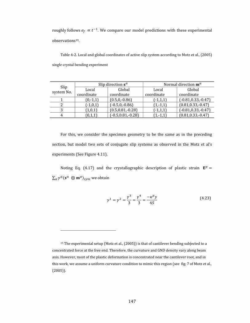
147
roughlyfollows ∝ .Wecompareourmodelpredictionswith theseexperimental
observations19.
Table 4‐2.LocalandglobalcoordinatesofactiveslipsystemaccordingtoMotzetal.,(2005)
singlecrystalbendingexperiment
SlipsystemNo.
Slipdirection NormaldirectionLocal
coordinateGlobal
coordinateLocal
coordinateGlobal
coordinate1 (0,‐1,1) (0.5,0,‐0.86) (‐1,1,1) (‐0.81,0.33,‐0.47)2 (‐1,0,1) (‐0.5,0,‐0.86) (1,‐1,1) (0.81,0.33,‐0.47)3 (1,0,1) (0.5,0.81,‐0.28) (‐1,1,1) (‐0.81,0.33,‐0.47)4 (0,1,1) (‐0.5,0.81,‐0.28) (1,‐1,1) (0.81,0.33,‐0.47)
For this,we consider the specimen geometry to be the same as in the preceding
section, butmodel two sets of conjugate slip systems as observed in theMotz et al’s
experiments(SeeFigure 4.11).
Noting Eq. ( 4.17) and the crystallographic description of plastic strain
∑ ⊗ weobtain
3 3 4
( 4.23)
19Theexperimentalsetup(Motzetal.,(2005))isthatofcantileverbendingsubjectedtoa
concentratedforceatthefreeend.Therefore,thecurvatureandGNDdensityvaryalongbeam
axis.However,mostoftheplasticdeformationisconcentratednearthecantileverroot,andin
thiswork,weassumeauniformcurvatureconditiontomimicthisregion(seefig.7ofMotzetal.,
(2005)).

148
Figure 4.11. Schematic of single crystal specimenunder pure bending, crystal orientationandcorrespondingactiveslipsystems.
The crystal orientation in the experimental set up satisfies the plane strain
conditions for plasticity, which is in agreement with our previous assumption in
derivinginternalstressconstitutiveequation.
Figure 4.12 compares the experimental variation (green curve and circles)
together with the theoretical predictions (dashed curves and symbols) with the
parameter values provided in Table 4‐120. The different dashed curves signify the
predicted variation for different values of . The blue dashed curve is the
predicted variationaccountingforonlytheGND‐SRIterminEq.( 4.22).Overthe
entire range of beam thicknesses investigated byMotz et al (2005) the predicted SRI
contribution to the overall strengthening falls short of the experimentally reported
strengthening indicating that there should be an additional contribution to
strengthening. Further, the discrepancy is accentuated with decreasing . That this
20Forcomparisonwiththeexperiment,weset 4soastoproducethesameamountof
SSDhardening(~70MPaat5%totalstrain)inordertoobtainthesize‐independentlimitofthe
macroscopicflowstressforbulkspecimens(Motzet.al,2005).
149
additionalcontributionshouldarisefrominternalstressesissubstantiatedbybending
experiments(Kieneretal.,2010)and(DemirandRaabe,2010)atsimilarlength‐scales,
but under cyclic loading,which exhibit pronounced length‐scale dependent kinematic
hardening(Bauschingereffect)duringloadreversal,alsopredictedby(Houetal.,2008)
in the DDP analysis of pure bending ofminiaturized beams. An interesting source of
deviation from the classic Taylor hardening model was recently highlighted by
Guruprasad and Benzerga (2008). They indicated that even under nominally
homogeneousloading(tensionorcompression),presenceoflocalGNDstructuresatthe
micro‐scale may cause additional hardening at small length‐scales, especially over
moderate to large strains. They also proposed an augmented hardening model to
accountforsuchhigher‐ordereffects.
Notethat for thevaluesof consideredinFigure 4.12,eachcurvecompareswell
with theexperimentonly inaparticular regimeofbeam thickness. Forexample,with
1 (red curve) thepredicted corroborateswellwithexperimental values for
large beam thickness 3.5 . However, for thinner beams the predicted
strengthening is much lower than the actual value. Interestingly, for beams with
3.5 oneobservesbettercorroborationwiththeexperimentforlargervaluesof
such that at the smallest 1 the predictions with 10 corroborate very
well with the experiments. Based on this comparison, it may be postulated that the
evolution of internal length‐scale changes with decreasing specimen thickness. It
becomes imperative to seek a plausible explanation for such a dependency, which is
discussedinthesubsequentparagraphs.

150
Figure 4.12.Comparisonoftheanalyticalresults(Eq.4.17)fordifferentvaluesof withtheexperimentalresultsofMotz,etal(2005).
Basedonthiscomparison,itmaybepostulatedthattheinternallength‐scaleitself
increaseswithdecreasingspecimenthickness.Itbecomesimperativetoseekaplausible
explanation for such a dependency,which is discussed in the subsequent paragraphs.
Onephysicalinterpretationoftheinternallength‐scale thatgovernsinternalstresses
in amesoscopic continuum is a correlation length‐scale emerging from the collective
behavior of dislocations21. (Groma, 1997, 2003; Groma and Bako, 2000; Groma and
21ZaiserandSeeger(2002)introducedmesoscopicinternalstressesarisingfromlong‐range
interactionsofdislocationensembles,whichvaryonthecharacteristicscaleofthedislocation
densityvariationincomparisontomicroscopicinternalstressesinthevicinityofasingle
dislocation.Basedonthisdefinition,theinternallength‐scaleassociatedwiththemesoscopic
Specimen thickness
1 2 3 4 5 6 7 80
100
200
300
400
500
600
700
800
900
1000 Experimental results (Motz, et. al. 2005) l
c=10 m
lc=3 m
lc=1 m
MSG-CP theory (Han, et. al. 2005) Conventional CP

151
Bakó, 1998; Zaiser and Aifantis, 2003; Zaiser et al., 2001; Zaiser and Seeger, 2002).
(HahnerandZaiser,1997)proposedascalinglawforcorrelationlength,whichgivesa
correlation length around 1 for deformed Cu in stage‐II hardening at room
temperature. For a given specimen, the initial may be defined by the starting
dislocation substructure or the initial dislocation sourcedistribution. Itmay evolve as
thedislocationsubstructureevolvesduringdeformation.Basedontheseideas,wemay
consider the relevant length‐scale to be the correlation distance over which
dislocationensemblesinteractthroughtheirstress‐fields.Conventionally isdescribed
intermsofmultiplesoftheaveragedislocationspacing , i.e.~ ⁄ ,where isthe
overall dislocation density (Weiss and Montagnat, 2007; Zaiser and Seeger, 2002).
Mughrabi(1975,1983,2001)suggestedthat shouldbe intherangeof10‐100times
the average dislocation spacing . On a given slip‐planewith dislocations arranged in
parallel (Figure 4.13), the average on that particular slip‐plane can be obtained
directly from their arrangement. However, normal to the slip‐plane the dislocation
spacing is set by another length‐scale , which is the distance between two adjacent
slip‐planes. The existenceof such aneffective slip‐plane spacing stems from the fact
thatnot all theplanes in aparticular slip systemareactivatedduring initial stagesof
deformation. Indeed, this natural length‐scale emerges from activation of dislocation
sources(e.g.Frank‐Readsources)onafewofthepotentialslip‐planes–aprocessthatis
statisticalinnature(Yefimovetal.,2004b).
continuumwassuggestedtobeoftheorderoffewmicrons(alsoseeWeissandMontagnat
(2007)).

152
Figure 4.13. Typical GND arrangement in double symmetric slip deformation under purebending.
Assumingforourcurrentproblem(Figure 4.13)thatthereexist dislocationsin
anarea where istheprojectedslip‐planespacing,theGNDdensitycomponent
canbewritteninadiscretesenseas
( 4.24)
where ⁄ on a given slip plane. For crystalline materials, (or ) is in the
rangeoftensofnanometers22(Deshpandeetal.,2005).Mesarovicetal(2010)showed
that appearsasanaturalinternallength‐scaleinthecontinuumdescriptionofinternal
stress by invoking the thermodynamic coarsening error between the discrete and
22 / cos istheprojectionoftheactualslip‐planespacing ,whichis~100 .

153
continuum descriptions of a GND density field. From a kinematic coarsening
perspective, if we smear out the dislocation arrangement along the slip‐plane by
adopting the notion of continuously distributed dislocations, but retain the discrete
nature of distribution across it, then the correlation length‐scalemaybedescribed as
(Mughrabi,(1975),ZaiserandSeeger(2002)andMesarovic,etal(2010))
( 4.25)
where ~10 100(Mugharbi, 1975) may be viewed as the number of slip planes
around a given point that influence the stress field at that point. For example,
if 30 , we obtain ~300 3 from Eq. ( 4.25), which is in the range
suggestedbyvariouscontinuumandDDPapproaches(Deshpandeetal.,2005;Hahner
and Zaiser, 1997; Weiss and Montagnat, 2007; Zaiser et al., 2001). Note that the
assumption of discreteness of slip‐planes may be relevant in a scenario where a
specimen initially hosts sparsely distributed dislocation sources, which would also
indicate activation of fewer slip‐planes giving a larger .Recent explorations in small
scalecrystalplasticityhaveresultedinproposalsforscale‐dependentplasticitythatrely
onnovelmechanismssuchasdislocationstarvation(GreerandNix,2006;Greeretal.,
2005),exhaustionhardening(Benzerga,2009)andsourcetruncation(El‐Awadyetal.,
2011; Kiener and Minor, 2011; Parthasarathya et al., 2007). It is likely that these
mechanismsmaycouple intothedescriptionof internalstressesthroughthenotionof
internal length‐scale. Although we do not explicitly account for such mechanisms,
comparison of our calculations with experiments provides an interesting perspective
fromtheviewpointofinternalstressesthatmayconnecttotheseproposals.
Now, based on our postulate that increases with decreasing (Figure 4.12), a
larger for smaller specimen means that either is larger for fixed ,or that more
numberof slip‐planesparticipate indetermining the internal stress at apoint. Three‐
dimensionalDDDsimulationsofsinglecrystallinebeamunderbendingforbothsingle

154
anddouble‐symmetricslip(Motz,et.al.(2008))showthatforsmallerbeamthicknesses,
fewerdislocationsourcesareactivatedgivingalowerinitialdislocationsourcedensity
thanforathickerbeam.Inthesamesimulations,plasticslipinthinnerbeamsoccursin
localizedslipbandsthatarespacedmuchwiderapartcomparedtothoseinthethicker
beamswhereslipbandsarecloseenoughtoresemblearelativelyhomogeneousplastic
slip. Asmentioned in the preceding paragraph, from the viewpoint of Eq. ( 4.24) and
Figure 4.12, this suggests that below a certain value of , for a fixed GND density a
reduction in theaveragedensityofdislocationsourcesshould indeed lead to theslip‐
planes being spaced wider apart, i.e. larger with smaller . This observation is also
consistentwiththenotionofsource‐limitedplasticityingeometricallyconfinedsystems
(El‐Awadyetal.,2009a;Espinosa,2005;Parthasarathyetal.,2007);Shi,et.al.(2004)).
FromFigure 4.12, (andtherefore, ) remainsnearlyconstantabove ~4 ,but
increasesdramaticallybelowthatvalue.
It is interesting to consider an allied length‐scale dependency from the
perspective introduced by Chakravarthy and Curtin (2010). For specimen under
uniaxial tension, their DD and continuum analysis showed that the amount of
strengthening increases with increasing ratio of the obstacle to dislocation source
density ⁄ forafixedspecimenthickness.Inthepresentcontext,thismaybe
viewed as follows: For a fixed , Eq. ( 4.24) requires that for a fixed (i.e. fixed
curvature) thenumberof dislocations in thepile‐upover the region must
increaseforalarger .Inotherwords,thereshouldbemoredislocationsperslip‐plane
to accommodate the same curvature. This is also akin to saying that the density of
obstacles to dislocation nucleation or motion per slip‐plane is higher, because
each new dislocationmust overcome the back stress produced by existing obstacles.
Further, higher means more widely spaced slip‐planes concomitant to fewer
dislocation sources, i.e. lower .With this, it can be postulated that the argument of
higher producing larger strengthening due to enhanced internal stress is also
155
consistent with the results of Chakravarthy and Curtin (2010). In the context of the
present problem,we obtain that for two specimens experiencing same curvature, the
specimenwiththesmallerthicknessexhibitshigheroverallinternalstressduetowider
slip‐planespacingthatcoupleswithmorenumberofdislocationsperslip‐planeacting
asobstaclestodislocationmotion.
In summary,we posit that the proposed origin of the inverse dependence of the
internal length‐scale corresponding to the internal stresses on the specimen size
stems from thepaucity of active slipplanes (arising from lackof sufficientnumberof
sourcesand/ortruncatedsources)thatdeterminetheiraveragespacing .Wenotein
passing that from Figure 4.8, this also means that the internal stress increases non‐
linearlywithdecreasing .
4.4.3 Length-scale Dependent Bauschinger Effect
Finally, we investigate the cyclic pure bending behavior of the single crystal
specimenusingdevelopedcontinuumframeworkintheprevioussection.Inparticular,
we mimic a single cycle comprising forward bending leading a prescribed plastic
curvature followedbystraightening tooriginalundeformedgeometry,whichhasbeen
experimentallyreportedtoexhibita length‐scaledependentBauschingereffect(Demir
andRaabe,2010).InEq.( 4.22)weset 0duringtheforwardloading.
Figure 4.14showsbending‐strengtheningresponsesofthesinglecrystalspecimens
underdoublesymmetricslipconditionfortwothicknesses, 1 and10 .There
areseveral interestingfeaturesthatcanbeextractedfromthisfigure.Firstly, itcanbe
seen that the length‐scaledependent internal stressescausemoresevereBauschinger
effect (yield asymmetry) for the thinner specimen than for the thicker specimen
(Kiener,(2010);DemirandRaabe(2010);Hayashi,et.al.(2011);Houet.al(2008)and
KurodaandTvergaard(2008)).Duringforwardloading,theinternalstressactsasback‐

156
stress that resists plastic deformation and manifests as macroscopic strengthening,
whileduringstraighteningthesameinternalstressassistsplasticdeformationcausinga
decreaseintheyieldstrength.DemirandRaabe(2010)referredtothisasamechanical
Bauschingereffect,whichisduetointernalstressesthatarisefrompolarizeddislocation
(GNDs) arrangement during forward bending. Secondly, the hardening rate in the
reverse plasticity is higher for thinner specimen. Finally, for a given thickness the
hardening rate in reverseplasticity is lower than in its forward counterpart. This last
aspectcanbeexplainedasaconsequenceoftheidealizedscenarioofnoSSDhardening
andvanishingGNDdensitywithdecreasingcurvatureasassumedinouranalysis.
Figure 4.14. Bending‐straightening cyclic response of single crystalline specimenorientedfordoublesymmetricslip
CorrespondingtoFig.4.14,theGND‐inducedSRIandLRItermsarenonzeroatthe
point of reverse yield and are equal to those at the strain atwhich unloading begins.
0.000 0.005 0.010 0.015 0.020
-6
-4
-2
0
2
4
6
lc=10 m, t=1 m
lc=1 m, t=10 m
CCP

157
These contributions gradually decrease with decreasing curvature until they vanish
when the specimen attains its original shape. Consequently, the overall stress also
becomesequal to theyieldstressdeterminedby (Eq.4.22). Inrealityhowever, the
presence of SSD density and the remobilization of GNDs as SSDs due to decreasing
curvature (Demir and Raabe, 2010) may produce a higher hardening rate in the
straighteningstage,whichisnotcapturedhere.Inadditiontheyobservedanenhanced
hardening during straighteningwith decreasing specimen thickness. This likely arises
because the GND density that evolves to accommodate increasing curvature during
forward loading progressively decreases during the straightening phase and this
accumulateddensitymanifestsitselfasincreasedmobiledislocationdensitythatmayin
turn enhance the overall hardening in the flow regime. In Figure 4.14, this effect is
accountedfor inthestraighteningphasewithintheTaylorhardeningterminasimple
waybyassumingthatthefractionalreductionintheGNDdensityisthesameasthatof
the fractional increase in the SSD density. The GND‐induced SRI and internal stress
termsarenonzeroatinitialstagesofunloading,butgraduallydecreasewithdecreasing
curvature until it reaches zero when the specimen attains its original shape.
Concurrently,thehardeningduetoremobilizedGNDdensitytermiszeroatinitialstage
ofunloading,butevolveswithstressreversal.
Figure 4.15 shows the overall stress variation across specimen thickness at
different levels of surface strain indicated by the open circles in Fig. 4.14.While CCP
(Figure 4.15a)exhibitsidenticalvariationoverthethicknessunderforwardandreverse
loading(noBauschingereffect),thelength‐scaledependentresults(Figure 4.15bandc)
showincreasinglystrongerasymmetrywithdecreasedspecimenthickness.Asexpected,
for the latter cases the stress distribution under forward loading shows increasingly
highersurfacestresswithdecreasingthicknessandalowersurfacestressunderreverse
loading.

158
(a)
(b)
(c)
Figure 4.15.Overallstressvariationacrossspecimenthicknessatdifferentstrainshowninfigure4.14.
Further,thestressdistributionoverthespecimenthicknessatthepointofreverse
yielding strongly depends on and (blue curves). Note that at the point of reverse
-6 -4 -2 0 2 4 6-1.0
-0.5
0.0
0.5
1.0
-6 -4 -2 0 2 4 6-1.0
-0.5
0.0
0.5
1.0
-6 -4 -2 0 2 4 6-1.0
-0.5
0.0
0.5
1.0
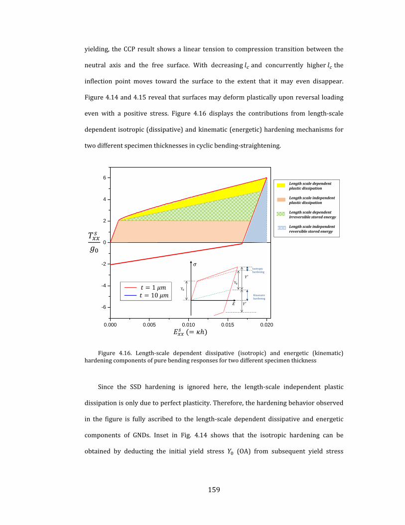
159
yielding, theCCPresult showsa linear tension to compression transitionbetween the
neutral axis and the free surface. With decreasing and concurrently higher the
inflection point moves toward the surface to the extent that it may even disappear.
Figure 4.14and4.15revealthatsurfacesmaydeformplasticallyuponreversalloading
even with a positive stress. Figure 4.16 displays the contributions from length‐scale
dependentisotropic(dissipative)andkinematic(energetic)hardeningmechanismsfor
twodifferentspecimenthicknessesincyclicbending‐straightening.
Figure 4.16. Length‐scale dependent dissipative (isotropic) and energetic (kinematic)hardeningcomponentsofpurebendingresponsesfortwodifferentspecimenthickness
Since the SSD hardening is ignored here, the length‐scale independent plastic
dissipationisonlyduetoperfectplasticity.Therefore,thehardeningbehaviorobserved
in the figure is fully ascribed to the length‐scale dependent dissipative and energetic
components of GNDs. Inset in Fig. 4.14 shows that the isotropic hardening can be
obtained by deducting the initial yield stress (OA) from subsequent yield stress
0.000 0.005 0.010 0.015 0.020
-6
-4
-2
0
2
4
6
LengthscaledependentplasticdissipationLengthscaleindependentplasticdissipationLengthscaledependentIrreversiblestoredenergyLengthscaleindependentreversiblestoredenergy
Isotropichardening
Kinematichardening

160
(BC/2).Thekinematichardening contribution isobtainedbydeducting from the
stressatthepointwheretheloadisreversed(pointBonthecurve).
Fromathermodynamicviewpoint,writingthetotalinternalenergy(seechapter3)
identifythedifferentcomponentsofenergyinvolvedinplasticdeformationas
:
∗:
∗
( 4.26)
The first term in Eq. ( 4.26) represents the length‐scale independent reversible
storedenergyassociatedwithexternallyappliedloads.Thesecondtermisreferredtoas
the length‐scale dependent irreversible stored energy as it is associated with the
internalresidualstressand incompatibleelasticstrainthatwill tendtoreorganizethe
GNDdensityfromanenergeticallyefficientconfiguration.ThethirdterminEq.( 4.26)is
theplasticdissipationduetotheSSD23(length‐scale independent isotropichardening)
andGND(length‐scaledependentisotropichardening)densities.
It can be seen than regardless of beam thickness, the contribution of energetic
hardening is higher than the dissipative onewhich is depicted in figure 4.10 aswell.
Furthermore, higher irreversible energy store and dissipate in thinner beam due to
polarizedGNDdistributionwhichprovide the length‐scaledependent responses.Note
that length scale dissipative energy arises from short‐range interaction of GNDswith
SSD and causes isotropic hardening, while long‐range elastic GND‐GND and GND‐
23Intheresultspresentedinfigure4.14and4.15,theSSDhardeningisneglectedbysetting
C=0inEq.(4.17)andplasticenergyisdissipatedonlybecauseofshortrangeinteractionofGNDs
withSSDs

161
boundaryinteractionscauseirreversibleenergy,sometimesreferredtoasdefectenergy
(Gurtin,2002)andcausekinematichardening(Bauschingereffect).
4.5 Summary and Outlook
Thischapterpresentsanelasticitybasedapproachtoaccountforimageeffectsdue
to GND‐free surface interaction producing length‐scale dependent internal stresses in
crystalplasticity.The approachdevelopedhere isgeneric in that the internal stresses
fromGNDdensityinaninfinitemediumiscorrectedbyanadditionaltermthataccounts
forGND‐boundarylong‐rangeinteraction.Thelatterexplicitlydependsonthenatureof
theboundaryandtheparticularcasetreatedhereisthatofafreesurface.Itshouldbe
possible to apply the concept to other continuum analogs based on fundamental
solutionssuchaselastichalf‐spacesandinterfacesbetweendissimilarmaterialsunder
homogeneousornon‐homogeneousdeformations.
The pure bending example shows that finite spatial extent of the GND density
produces net long‐range elastic interactionwhen image fields are taken into account
thatmanifestas internalstressesevenwhentheGNDdensityisuniformlydistributed.
Theresultsshowthattheseeffectsbecomeincreasinglyimportantasthecharacteristic
specimen size approaches the internal material length‐scale. If the specimen size is
much larger than the internal length‐scale the internal stresses are still non‐zero, but
onlyintheproximityofthefreesurfaces.Aproposalthatstemsfromthepresentwork
is thenatureof the internal length‐scale contributing toward internal stresses.This is
expressed in terms of the average slip‐plane spacing through the dislocation density
argument. A comparison of the model predictions with experimental results on
monotonic micro‐beam bending suggests that the initial internal length‐scale should
increasewithdecreasingcharacteristic specimensize.Thisproposal is rationalizedby
appealingtorecentexperimentalandcomputationalresultsonminiaturizedspecimens

162
subjected to homogeneous or non‐homogeneous loading. Cyclic responses of the
specimens under pure bending and straightening are also explored and the
experimentallyobserved length‐scaledependentBauschingereffect iscaptured.Again,
it is important to note that this effect stems from the GND‐free surface long‐range
interaction. The resulting contributions of the isotropic and kinematic hardening are
quantifiedinthestress‐strainresponses.
In closing,wewould like tomention the recentworkbyCherednichenko (2010)
that introduces the idea of continuum representation of image fields, although the
underlying mathematical representation is different from ours. In comparison to the
presentwork thatrelieson the theoryofelasticityandkinematic incompatibility, that
workconstructsimagefieldsthroughstatistical‐mechanicsbasedensembleaveragingof
dislocations (Groma, 1997; Groma and Balogh, 1999; Yefimov et al., 2004), similar to
that of Vinogradov and Willis (2008). The resulting elegant formulation embeds an
enriched nonlocal constitutive law that tracks plasticity through dislocation density
evolution includingnucleation,whileaccounting for imageeffects.Although the image
fieldsconstructedthereare foradifferentboundaryvalueproblem(simpleshearofa
constrainedthinstriparisingwheredislocationspile‐upatthehardboundary),itwould
beinterestingtodrawbroadcorrelationsbetweenthesetwoapproaches.

163
5 Summary and Recommendations
In thischapter,wesummarize thekeycontributionsof this thesisandprovidean
outlookintothefuturedevelopmentsalongthechosendirection.
5.1 Summary
Classical continuum crystal plasticity theories are successful to predict inelastic
behaviorofmaterialinmacroscopicscalewhileitfailstocapturesizedependencyofthe
material when sub structural counterparts or specimen sizes are comparable with
microstructuralcharacteristic length.Therefore, toexplainsomeof theexperimentally
observed length‐scale responses in crystalline materials, traditional continuum
mechanics of plastic deformation is augmented with a variety of dislocation related
mechanisms. In this thesis, we explore the length‐scale dependent behaviors of FCC
crystallinematerials in terms of GND interactionmechanisms at different scales. The
threeGNDrelatedmechanismsinvestigatedinthisthesisaresummarizedasfollows:
(i) Short‐range interactionbetweenGNDs and SSDs is considered in chapter 2 in
termsoflength‐scaledependentTaylorhardeningmodel.Thisphenomenonismodeled
using the Mechanism‐based Slip Gradient Crystal Plasticity (MSG‐CP), which is
implemented by the author as a user‐material subroutine (UMAT) within
ABAQUS/STANDARD®.Usingthisimplementation,thelength‐scaledependentbehavior
ofmodel single crystalMMC architectures under thermal andmechanical loading are
investigated.Specifically,roleofinitialthermalGNDdensityonthesubsequentresponse
undermechanical loading is investigated for certain crystal orientations. The length‐
scale dependent thermo‐mechanical response is modeled as a two‐step procedure
withinfiniteelementanalysisthatcloselyfollowstheactualsynthesisroute.Theresults

164
exhibit the characteristic tension‐compression asymmetry arising from pre‐existing
internal(thermally‐induced)residualstressesthatisnowlength‐scaledependent.
(ii)AnotherimportantresultthatemanatesfromtheMSGCP‐MMCinvestigationsis
the negligible effect of inclusion shape (whether round or sharp‐cornered) at small
sizes.Thisisbecausethehightriaxialitythatexistsinthematrixsurroundingthesharp
corners issmearedoutbythehardenedGNDzonearoundthe inclusions that isabout
thesamespatialextentasthestressconcentrationatcorners.
(iii) The MSGCP implementation is also used in systematic simulations of
polycrystalline MMC architecture to delineate the interaction strengthening
contributionasarisingfromthegrainsizeandtheinclusionsizeinteraction.Thiseffect
hasbeentraditionallyignoredinMMCsimulationsto‐date.Oursimulationspredictthat
theinteractiontermappearsasHall‐Petchtypecontribution.Basedonthisobservation,
weproposeananalyticalsolution for this interactioneffectbasedon the ideathat the
inclusion‐grainintersectionsactasspecialsourcesthatemitadditionalGNDsandthese
GNDspile‐upatgrainboundariesresultinginadditionalstrengthening. .Theproposed
analyticalmodelisdeemedamenabletohomogenizedapproaches.
(iv) The thesis then expands its scope to address the length‐scale dependent
internal stress arising from long‐range GND‐GND interaction. A nonlocal continuum
crystalplasticityisdevelopedtoaccountfortheseresidualstressesarisingfromanon‐
homogeneous distribution of GND density. The thesis proposes a stress functions
approach to analytically derive the length‐scale dependent 3D internal stress tensor.
This internal stress tensor is incorporated into continuum framework using
thermodynamiclaws.
(v) The model examples treated semi‐analytically with the aforementioned
formulation highlight the importance of the internal stress on the length‐scale
dependent strengthening and hardening in single crystals. The tapered single crystal

165
example that approximately mimics a micro‐pillar subjected uniaxial loading
substantiatesthatofgeometricimperfectionsinsuchstructurescausestronggradients
intheGNDdensityand leadtoastrengtheningoftheoverallstress‐strainresponsein
specimensthataresubjectedtonominallyuniaxialmacroscopicloads.Thesimpleshear
of a single crystal lamellamimics a nano‐twinwithina grain thatundergoes shearing
deformationandtheinternalstress‐inducedstrengtheningofaslipsystemexhibitsHall‐
Petch typebehavior. Interestingly, at small structural sizes the strengthening tends to
saturate.
(vi) Finally, the thesis addresses the long‐range interaction between the GND
densityandtraction‐freeboundaries.Buildinguponthestressfunctionsapproach,the
internal stress formulation incorporates additional image stresses due to this
contributionthroughanadditionalstressfunction.Theresulting internalstresstensor
representing image fields is length‐scale dependent. In analyzing a model micro‐
architecturecomprisingasinglecrystal thin filmunderpurebending, it isshownthat
internalstressesalsooccurundernominallyuniformcurvatures.Theformalismreveals
thatthemicro‐tractionboundaryconditionsintheformofPeach‐Koehlerforcedensity
due toGNDdensity invoked in thework of Gurtin (2002) can be construed as image
stresses imposed due to GND‐surface long‐range interaction. A comparison with the
experimental results suggests that internal length‐scale is a functionof structural and
microstructural dimensions and may increase with decreasing specimen dimensions.
The structurally dependent internal length‐scale is explained in terms of the recent
proposals of paucity of dislocation sources and enhancement of obstacle densitywith
decreasingstructuraldimensions.

166
5.2 Recommendations for future work
The work compiled in this thesis may serve to provide a basis to variety of
problems in themechanics and physics of length‐scale dependent plasticity. Some of
theseareidentifiedanddiscussedhere:
(i)IntheMMCmodeling,wehaveassumedhighlyidealizedmicrostructuresinthe
form of grain shapes and inclusion arrangement. Further, it may be useful to mimic
microstructures that are closer to the real microstructures. A simple, yet plausible
approximation could be that of hexagonally‐shaped grains rather than the square‐
shaped approximations chosen in this work. The former would be a better
approximation, because typically one finds triple junctions in real microstructures
unlikethequad‐junctionsinthemicrostructurewithsquaregrains.
(ii) The length‐scale dependent MMC behaviors including thermo‐mechanical
loading conditions may be extended to polycrystalline microstructures. This would
require invoking the elastic anisotropy of the crystals to render differential stresses
acrossgrainboundaries,whichisalreadypresent intheMSGCPUMATdevelopedhere
butwasnotusedforsimplicity.
(iii) The area of hierarchical MMCs (Joshi and Ramesh, 2007) is an exciting
direction to use the MSGCP approach. Several local and global features of such
composite‐within‐compositearchitecturescanbeinvestigatedwithhighresolutionasa
functionofjudiciouslyarrangedtopologieswithvaryinggrainsizes.
(iv) Our MMC investigations do not invoke higher‐order boundary conditions,
whichwould be necessary to capture enhanced interactions between the dislocations
and interfaces. Therefore, it would be worthwhile to endow the current crystal
plasticity code with higher‐order gradients. Within ABAQUS, this would entail
developing a full‐fledged user‐element (UEL) that would enable calculating second

167
gradients of plastic slip (i.e. first gradient of the GND density), of which the current
UMATwouldbeapart.
(v)Thestress functionsapproachtoaccount for internalstresseswhileattractive
and insightful, has limitations that explicit solutions are possible only for a limited
numberofcasessuchasthosewithregulargeometry,idealboundaryconditions,elastic
isotropy.Although,wehaveprovidedabriefoutlineoftheextensionofthisapproachto
elastically anisotropic materials, a complete solution to a boundary value problem is
expected to be quite complicated. Hence, it may be useful, or perhaps necessary, to
developafiniteelementapproachthatcalculatestheseinternalstresses.
(vi) In thecontextofstress functionapproachwhichhasdeveloped inthis thesis,
some fundamental caseswhich are interesting for largemechanics community canbe
investigated where appropriate Green functions are available or can be derived. For
instance,
‐ Torsion of single crystalline micro wire comprising uniform distribution of
screwdislocation.
‐ MMC unit cell comprising circular inclusion and crystalline matrix where
internal stresses develop at the inclusion/matrix interface due to dislocation
pilesup.
‐ Microcompressionoftaperedpillaraccountingforimageeffects.
(viii) Alternatively, the surface dislocationmodel proposed by Jagannadham and
Marcinkowski (1978) can be incorporated to account for image effect while simple
infinitemediumgreenfunctionsareused.
(viii) In the case of complicated topologies and non‐ideal higher‐order traction
boundary conditions, the stress function approach is not a very useful approach to

168
obtain image fields. A brief discussion and a possible approach are outlined in the
closingsectionofChapter4,whichshouldprovideadirectionforfuturework.

169
6 List of Publication
ArticlespublishedinJournals:Aghababaei,RandJoshi,SP(2011)Grainsize–inclusionsizeinteractionin
metal matrix composites using mechanism‐based gradient crystal plasticity.International Journal of Solids and Structures, 48 (18) 2585‐2594.
Aghababaei,R,Joshi,SPandReddy,JN(2011)Nonlocalcontinuumcrystalplasticitywithinternalresidualstresses.JournaloftheMechanicsandPhysicsofSolids,59,713–731.
Aghababaei, R and Reddy, JN (2009), Nonlocal Third‐Order Shear
DeformationPlateTheorywithApplication toBendingandVibrationofPlates.JournalofSoundandVibration,326,277‐289.
Articlesinpreparation/submission:
Aghababaei,RandJoshi,SP.ACrystalPlasticityAnalysisofLength‐scale Dependent Internal Stresses with Image Effects (under review inJournaloftheMechanicsandPhysicsofSolids).
Aghababaei, R and Joshi, SP. Length‐scale dependent compositeresponse induced by thermal residual stresses (manuscript inpreparation)
Conferencepresentations:
Aghababaei,RandJoshi,SP(2011)GrainSize‐InclusionSizeInteractioninMetal Matrix Composites at Moderate Strains. International Conference onMaterials forAdvancedTechnologies, ICMAT, (June26‐July 1, 2010), Singapore.Aghababaei, R, Joshi, SP and Reddy, JN (2010) A Nonlocal ContinuumTheoryAccounting for SizeDependentBauschingerEffect.9thWorldCongresson ComputationalMechanics and 4th Asian Pacific Congress on ComputationalMechanics,WCCM/APCOM2010 (19 – 23 July 2010), Sydney, AustraliaAghababaei, R and Joshi, SP (2010) A Nonlocal Continuum TheoryAccountingforSizeDependentBauschingerEffect.16thUSNationalCongressonTheoreticalandAppliedMechanics,USNCTAM(June27‐July2,2010),PennStateUniversity, Pennsylvania, USAAghababaei R, Joshi, SP and Zhang, J (2010) Length‐Scale DependentResponseofHierarchicalCompositesusingEnrichedPolycrystalPlasticity.16thUSNationalConCongressonTheoreticalandAppliedMechanics(June27‐July2,2010),PennStateUniversity,Pennsylvania,USA.

170
7 Bibliography
AbuAl‐Rub,R.K.,2009.Modelingtheparticlesizeandinterfacialhardeningeffectsinmetalmatrixcompositeswithdispersedparticlesatdecreasingmicrostructurallengthscales.InternationalJournalforMultiscaleComputationalEngineering7,329‐350.
AbuAl‐Rub,R.K.,Voyiadjis,G.Z.,2006.Aphysicallybasedgradientplasticitytheory.InternationalJournalofPlasticity22,654‐684.
AbuAl‐Rub,R.K.,Voyiadjis,G.Z.,Bammann,D.,2007.Athermodynamicbasedhigher‐ordergradienttheoryforsizedependentplasticity.InternationalJournalofSolidsandStructures44,2888‐2923.
Acharya,A.,2003.Geometricallynecessarydislocations,hardening,andasimplegradienttheoryofcrystalplasticity.ScriptaMaterialia48,167‐172.
Acharya,A.,Bassani,J.L.,2000.Latticeincompatibilityandagradienttheoryofcrystalplasticity.Journalofmechanicsandphysicsofsolids48,1565‐1595.
Acharya,A.,Beaudoin,A.J.,2000.Grain‐sizeeffectinviscoplasticpolycrystalsatmoderatestrains.J.Mech.Phys.Solids48,2213‐2230.
Acharya,A.,Roy,A.,2006.Sizeeffectsandidealizeddislocationmicrostructureatsmallscales:PredictionsofaPhenomenologicalmodelofMesoscopicFieldDislocationMechanics:PartI.JournaloftheMechanicsandPhysicsofSolids54,1687‐1710.
Agrawal,R.,Peng,B.,Gdoutos,E.E.,Espinosa,H.,2008.ElasticitysizeeffectsinZnOnanowires‐‐acombinedexperimental‐computationalapproach.NanoLetters8,3668‐3674.
Aifantis,E.C.,1984.OntheMicrostructuralOriginofCertainInelasticModels.JournalofEngineeringMaterialsandTechnology106,326‐330.
Aifantis,E.C.,1987.Thephysicsofplasticdeformation.InternationalJournalofPlasticity3,211‐247.
Anand,L.,Gurtin,M.E.,Lele,S.P.,Gething,C.,2005.Aone‐dimensionaltheoryofstrain‐gradientplasticity:Formulation,analysis,numericalresults.JournaloftheMechanicsandPhysicsofSolids53,1789‐1826.
Armstrong,P.J.,Frederick,C.O.,1966.AmathematicalrepresentationofmultiaxialBauschingereffect.,GEGBreportRD/B/N731.BerkeleyNuclearLaboratories.

171
Arsenault,R.J.,Shi,N.,1986.Dislocationgenerationduetodifferencesbetweenthecoefficientsofthermalexpansion.MaterialsScienceandEngineering81,175‐187.
Arsenault,R.J.,Taya,M.,1987.Thermalresidualstressinmetalmatrixcomposite.ActaMetallurgicaetMaterialia35,651‐659.
Arsenlis,A.,Parks,D.M.,1999.Crystallographicaspectsofgeometrically‐necessaryandstatistically‐storeddislocationdensity.ActaMaterialia47,1597‐1611.
Asaro,R.J.,1983.Micromechanicsofcrystalsandpolycrystals.AdvancesinAppliedMechanics23,1‐115.
Asaro,R.J.,Rice,J.R.,1977.Strainlocalizationinductilesinglecrystals.JournaloftheMechanicsandPhysicsofSolids25,309‐338.
Ashby,M.F.,1970.Thedeformationofplasticallynon‐homogeneousmaterials.PhilosophicalMagazine21,399‐424.
Balint,D.S.,Deshpande,V.S.,Needleman,A.,VanderGiessen,E.,2005.Adiscretedislocationplasticityanalysisofgrain‐sizestrengthening.MaterialsScienceandEngineeringA,186–190.
Bardella,L.,2006.Adeformationtheoryofstraingradientcrystalplasticitythataccountsforgeometricallynecessarydislocations.JournalofMechanicsandPhysicsofSolids54,128‐160.
Bardella,L.,2008.Influenceofmaterialparametersandcrystallographyonthesizeeffectsdescribablebymeansofstraingradientplasticity.JournalofMechanicsandPhysicsofSolids56,2906‐2934.
Bardella,L.,Giacomini,A.,2008.Influenceofmaterialparametersandcrystallographyonthesizeeffectsdescribablebymeansofstraingradientplasticity.J.Mech.Phys.Solids56,2906‐2934.
Barlow,C.Y.,Hansen,N.,1995.Dislocationconfigurationsinmetal‐matrixcompositescorrelatedwithnumericalpredictions.ActaMetallurgicaetMaterialia43,3633‐3648.
Barlow,C.Y.,Liu,Y.L.,1998.Microstructure,strainfieldsandflowstressindeformedmetalmatrixcomposites.ActaMaterialia46,5807‐5817.
Bassani,J.L.,Wu,T.Y.,1991.Latenthardeninginsinglecrystalsii.Analyticalcharacterizationandpredictions.ProceedingsoftheRoyalSocietyA435,21‐41.

172
Bayley,C.,Brekelmans,W.,Geers,M.,2006.Acomparisonofdislocationinducedbackstressformulationsinstraingradientcrystalplasticity.InternationalJournalofSolidsandStructures43,7268‐7286.
Benzerga,A.,2009.Micro‐pillarplasticity:2.5Dmesoscopicsimulations.JournalofMechanicsandPhysicsofSolids57,1459‐1469.
Borg,U.,2007.Astraingradientcrystalplasticityanalysisofgrainsizeeffectsinpolycrystals.EuropeanJournalofMechanics‐A/Solids26,313‐324.
Boukai,A.I.,Bunimovich,Y.,Tahir‐Kheli,J.,Yu,J.K.G.,W.A.,Heath,J.R.,2008.Siliconnanowiresasefficientthermoelectricmaterials.Nature451,168‐171.
Burger,J.M.,1939.SomeConsiderationsontheFieldsofStressConnectedwithDislocationsinaRegularCrystalLattice.I.KoninklijkeNederlandseAkademievanWetenschappen.
Cailletaud,G.,1992.Amicromechanicalapproachtoinelasticbehaviourofmetals.InternationalJournalofPlasticity8,55‐73.
Cazacu,O.,Fivel,M.,2010.DiscreteDislocationDynamics:PrinciplesandRecentApplications,in:Cazacu,O.(Ed.),MultiscaleModelingofHeterogenousMaterials:FromMicrostructuretoMacro‐scaleProperties.wiley.
Cermellia,P.,Gurtin,M.E.,2000.Onthecharacterizationofgeometricallynecessarydislocationsinfiniteplasticity.JournalofMechanicsandPhysicsofSolids49,1539‐1568.
Chakravarthy,S.S.,Curtin,W.a.,2010.Effectofsourceandobstaclestrengthsonyieldstress:Adiscretedislocationstudy.JournaloftheMechanicsandPhysicsofSolids58,625‐635.
Chen,C.R.,Qin,S.Y.,Li,S.X.,Wen,J.L.,1999.FiniteelementanalysisabouteffectsofparticlemorphologyonmechanicalresponseofcompositesmaterialsscienceandEngineeringA278,96‐105.
Cherednichenko,K.D.,2010.Anapproachtoconstitutivemodellingofelasto‐plasticityviaensembleaveragingofthedislocationtransport.JournaloftheMechanicsandPhysicsofSolids58,798‐809.
Choi,Y.,Suresh,S.,2002.Sizeeffectsonthemechanicalpropertiesofthinpolycrystallinemetalfilmsonsubstrates.ActaMaterialia50,1881‐1893.

173
Chou,Y.T.,Pande,C.S.,Yang,H.C.,1975.Interfacialedgedislocationsanddislocationwallsinanisotropictwo‐phasemedia.JournalofAppliedPhysics46,5‐10.
Christman,T.,Needleman,A.,Suresh,S.,1989.Anexperimentalandnumericalstudyofdeformationinmetal‐ceramic.ActaMetallurgicaetMaterialia37,3029–3050.
Cleveringa,H.H.M.,VanderGiessen,E.,Needleman,A.,1997.Comparisonofdiscretedislocationandcontinuumplasticitypredictionsforacompositematerial.ActaMaterialia45,3136‐3179.
Cleveringa,H.H.M.,VanderGiessen,E.,Needleman,A.,1999.Adiscretedislocationanalysisofbending.InternationalJournalofPlasticity15,837‐868.
Corbin,S.F.,Wilkinsona,D.S.,1994.Theinfluenceofparticledistributiononthemechanicalresponseofaparticulatemetalmatrixcomposite.ActaMetallurgicaetMaterialia42,1311‐1318.
Dai,L.H.,Ling,Z.,Bai,Y.L.,1999.Astraingradient‐strengtheninglawforparticlereinforcedmetalmatrixcomposites.ScriptaMaterialia41,245‐251.
Dai,L.H.,Ling,Z.,Bai,Y.L.,2001a.Size‐dependentinelasticbehaviorofparticle‐reinforcedmetal‐matrixcomposites.CompositesScienceandTechnology61,1057‐1063.
Dai,L.H.,Ling,Z.,Bai,Y.L.,2001b.Size‐dependentinelasticbehaviorofparticle‐reinforcedmetal–matrixcomposites.CompositesScienceandTechnology61,1057‐1063.
Dai,L.H.L.,Z.,Bai,Y.L.,2001.Size‐dependentinelasticbehaviorofparticle‐reinforcedmetal–matrixcomposites.CompositesScienceandTechnology61,1057‐1063.
Dehm,G.,2009.Miniaturizedsingle‐crystallinefccmetalsdeformedintension:Newinsightsinsize‐dependentplasticity.ProgressinMaterialsScience54,664‐688.
Demir,E.,Raabe,D.,2010.Mechanicalandmicrostructuralsingle‐crystalBauschingereffects:Observationofreversibleplasticityincopperduringbending.ActaMaterialia58,6055‐6063.
Deshpande,V.S.,Needleman,A.,VanderGiessen,E.,2005.Plasticitysizeeffectsintensionandcompressionofsinglecrystals.JournaloftheMechanicsandPhysicsofSolids53,2661‐2691.

174
Dunand,D.C.,Mortensen,A.,1990.Onplasticrelaxationofthermalstressesinreinforcedmetals.ActaMetallurgicaetMaterialia39,127‐139.
Dunand,D.C.,Mortensen,A.,1991.Dislocationemissionatfibers—II.Experimentsandmicrostructureofthermalpunching.ActaMetallurgicaetMaterialia39,1417‐1429.
El‐Awady,J.a.,Rao,S.I.,Woodward,C.,Dimiduk,D.M.,Uchic,M.D.,2011.Trappingandescapeofdislocationsinmicro‐crystalswithexternalandinternalbarriers.InternationalJournalofPlasticity27,372‐387.
El‐Awady,J.A.,Wen,M.,Ghoniem,N.M.,2009a.Theroleoftheweakest‐linkmechanismincontrollingtheplasticityofmicropillars.JournaloftheMechanicsandPhysicsofSolids57,32‐50.
El‐Awady,J.A.,Woodward,C.,Dimiduk,D.M.,Ghoniem,N.M.,2009b.Effectsoffocusedionbeaminduceddamageontheplasticityofmicropillars.PhysicalReviewB80,104‐109.
Endy,D.,2005.Foundationsforengineeringbiology.Nature438,449‐453.
Ertürk,İ.,vanDommelen,J.A.W.,Geers,M.G.D.,2009.Energeticdislocationinteractionsandthermodynamicalaspectsofstraingradientcrystalplasticitytheories.JournaloftheMechanicsandPhysicsofSolids57,1801‐1814.
Espinosa,H.D.,2005.Aninterpretationofsize‐scaleplasticityingeometricallyconfinedsystems.ProceedingsoftheNationalAcademyofSciences102,16933‐16938.
Evans,A.G.,Hutchinson,J.W.,2009.Acriticalassessmentoftheoriesofstraingradientplasticity.ActaMaterialia57,1675‐1688.
Evers,L.P.,Brekelmans,W.,Geers,M.G.D.,2004.Non‐localcrystalplasticitymodelwithintrinsicSSDandGNDeffects.JournaloftheMechanicsandPhysicsofSolids52,2379‐2401.
Fivel,M.C.,Gosling,T.J.,Canova,G.R.,1996.Implementingimagestressesina3Ddislocationsimulation.ModellingandSimulationinMaterialsScienceandEngineering4,581‐596.
Fleck,N.,Ashby,M.F.,Hutchinson,J.,2003.Theroleofgeometricallynecessarydislocationsingivingmaterialstrenghening.ScriptaMaterialia48,179‐183.
Fleck,N.,Hutchinson,J.,1997.StrainGradientPlasticity.AdvancesinAppliedMechanics33,295‐361.

175
Fleck,N.A.,Hutchinson,J.W.,1993.Aphenomenologicaltheoryforstraingradienteffectsinplasticity.JournaloftheMechanicsandPhysicsofSolids41,1825‐1857.
Fleck,N.A.,Hutchinson,J.W.,2001.Areformulationofstraingradientplasticity.JournalofMechanicsandPhysicsofSolids49,2245‐2271.
Fleck,N.A.,Hutchonson,J.W.,1993.Aphenomenologicaltheoryforstraingradienteffectsinplasticity.JournalofMechanicsandPhysicsofSolids41,1825‐1857.
Fleck,N.A.,Muller,G.M.,Ashby,M.F.,Hutchinson,J.W.,1994.Straingradientplasticity:TheoryandExpriment.ActaMetallurgicaetMaterialia42,475‐487.
Forest,S.,2008.SomelinksbetweenCosserat,straingradientcrystalplasticityandthestatisticaltheoryofdislocations.PhilosophicalMagazine88,3549‐3563.
Forest,S.,Aifantis,E.C.,2010.Somelinksbetweenrecentgradientthermo‐elasto‐plasticitytheoriesandthethermomechanicsofgeneralizedcontinua.InternationalJournalofSolidsandStructures47,3367‐3376.
Fotuhi,a.,Fariborz,S.,2008.Stressanalysisinacrackedstrip.InternationalJournalofMechanicalSciences50,132‐142.
Fratzl,P.W.,R.,2007.Nature’shierarchicalmaterials.ProgressinMaterialsScience52,1263‐1334.
Frederick,C.O.,Armstrong,P.J.,2007.AmathematicalrepresentationofthemultiaxialBauschingereffect.MaterialsatHighTemperatures,24,1‐26.
Fredriksson,P.,Gudmundson,P.,Mikkelsen,L.P.,2009.Finiteelementimplementationandnumericalissuesofstraingradientplasticitywithapplicationtometalmatrixcomposites.InternationalJournalofSolidsandStructures46,3977‐3987.
Frick,C.P.,Clark,B.G.,Orso,S.,Schneider,A.S.,Arzt,E.,2008.Sizeeffectonstrengthandstrainhardeningofsmall‐scale[111]nickelcompressionpillars.MaterialsScienceandEngineeringA489,319‐329.
Gao,H.,2001.Taylor‐basednonlocaltheoryofplasticity.InternationalJournalofSolidsandStructures38,2615‐2637.
Gao,H.,Huang,H.,Nix,W.,Hutchinson,J.,1999.Mechanism‐basedstraingradientplasticity‐I.Theory.JournalofMechanicsandPhysicsofSolids47,1239‐1263.
176
Gao,H.,Huang,Y.,2003.Geometricallynecessarydislocationandsize‐dependentplasticity.ScriptaMaterialia48,113‐118.
Gao,H.,Ji,B.,Jager,I.L.,Arzt,E.,Fratzl,P.,2003.Materialsbecomeinsensitivetoflawsatnanoscale:lessonsfromnature.ProceedingsoftheNationalAcademyofSciences100,5597‐5600.
Geers,M.G.D.,Brekelmans,W.A.M.,Bayley,C.J.,2007.Second‐ordercrystalplasticity:internalstresseffectsandcyclicloading.ModellingandSimulationinMaterialsScienceandEngineering15,S133‐S145.
Gerken,J.,Dawson,P.,2008.Acrystalplasticitymodelthatincorporatesstressesandstrainsduetoslipgradients.JournaloftheMechanicsandPhysicsofSolids56,1651‐1672.
Gianola,D.S.,Petegem,S.V.,Legros,M.,Brandstetter,S.,Swygenhoven,H.V.,Hemker,K.J.,2006.Stress‐assisteddiscontinuousgraingrowthanditseffectonthedeformationbehaviorofnanocrystallinealuminumthinfilms.ActaMaterialia54,2253‐2263.
Giessen,E.V.D.,Needleman,A.,1995.Discretedislocationplasticity:asimpleplanarmodel.Engineering689.
Greer,J.R.,Hosson,J.T.M.,2011.Plasticityinsmall‐sizedmetallicsystems:Intrinsicversusextrinsicsizeeffect.ProgressinMaterialsScience56,654‐724.
Greer,J.R.,Nix,W.D.,2006.Nanoscalegoldpillarsstrengthenedthroughdislocationstarvation.PhysicalReviewB73,245410.
Greer,J.R.,Oliver,W.C.,Nix,W.D.,2005.Sizedependenceofmechanicalpropertiesofgoldatthemicronscaleintheabsenceofstraingradients.ActaMaterialia53,1821‐1830.
Groma,I.,1997.Linkbetweenthemicroscopicandmesoscopiclength‐scaledescriptionofthecollectivebehaviorofdislocations.PhysicalReviewB56,5807‐5813.
Groma,I.,2003.Spatialcorrelationsandhigher‐ordergradienttermsinacontinuumdescriptionofdislocationdynamics.ActaMaterialia51,1271‐1281.
Groma,I.,Bako,B.,2000.Dislocationpatterning:frommicro‐tomesoscaledescription.PhysicalReviewLetters84,1487‐1490.
Groma,I.,Bakó,B.,1998.Probabilitydistributionofinternalstressesinparallelstraightdislocationsystems.PhysicalReviewB58,2969‐2974.

177
Gudmundson,P.,2004.Aunifiedtreatmentofstraingradientplasticity.JournaloftheMechanicsandPhysicsofSolids52,1379‐1406.
Gurtin,M.E.,2000.Ontheplasticityofsinglecrystals:freeenergy,microforces,plastic‐straingradients.JournaloftheMechanicsandPhysicsofSolids48,989‐1036.
Gurtin,M.E.,2002.Agradienttheoryofsingle‐crystalviscoplasticitythataccountsforgeometricallynecessarydislocations.JournaloftheMechanicsandPhysicsofSolids50,5‐32.
Gurtin,M.E.,2010.Afinite‐deformation,gradienttheoryofsingle‐crystalplasticitywithfreeenergydependentontheaccumulationofgeometricallynecessarydislocations.InternationalJournalofPlasticity26,1073‐1096.
Gurtin,M.E.,Anand,L.,2005.Atheoryofstrain‐gradientplasticityforisotropic,plasticallyirrotationalmaterials.PartI:Smalldeformations.JournaloftheMechanicsandPhysicsofSolids53,1624‐1649.
Gurtin,M.E.,Anand,L.,Lele,S.P.,2007.Gradientsingle‐crystalplasticitywithfreeenergydependentondislocationdensities.JournaloftheMechanicsandPhysicsofSolids55,1853‐1878.
Guruprasad,P.,Benzerga,A.,2008.Sizeeffectsunderhomogeneousdeformationofsinglecrystals:Adiscretedislocationanalysis☆.JournaloftheMechanicsandPhysicsofSolids56,132‐156.
Habibi,M.K.,Joshi,S.P.,Gupta,M.,2010.Hierarchicalmagnesiumnano‐compositesforenhancedmechanicalresponse.ActaMaterialia58,6104‐6114.
Hahner,P.,Zaiser,M.,1997.Frommesoscopicheterogeneityofsliptomacroscopicfluctuationsofstressandstrain.ActaMaterialia45,1067‐1075.
Han,C.‐S.,Gao,H.,Huang,Y.,Nix,W.D.,2005a.Mechanism‐basedstraingradientcrystalplasticity—I.Theory.JournaloftheMechanicsandPhysicsofSolids53,1188‐1203.
Han,C.‐S.,Gao,H.,Huang,Y.,Nix,W.D.,2005b.Mechanism‐basedstraingradientcrystalplasticity—II.Analysis.JournaloftheMechanicsandPhysicsofSolids53,1204‐1222.
Haque,M.A.,Saif,M.T.A.,2003.Straingradienteffectinnanoscalethinfilms.ActaMaterialia51,3053‐3061.

178
Haque,M.A.S.,M.T.A.,2004.Deformationmechanismsinfree‐standingnanoscalethinfilms:Aquantitativeinsitutransmissionelectronmicroscopestudy.ProceedingsoftheNationalAcademyofSciences101,6335‐6340.
Hartmaier,A.,Fivel,M.C.,Canova,G,R.,Gumbsch,P.,1999.Imagestressesinafree‐standingthinfilm.ModellingandSimulationinMaterialsScienceandEngineering7,781.
Hayashi,I.,Sato,M.,Kuroda,M.,2011.Strainhardeninginbentcopperfoils.JournalofMechanicsandPhysicsofSolids59,1731‐1751.
Head,a.K.,1953.EdgeDislocationsinInhomogeneousMedia.ProceedingsofthePhysicalSociety.SectionB66,793‐801.
Hill,R.,Rice,J.,1972.Constitutiveanalysisofelastic‐plasticcrystalsatarbitrarystrain.JournaloftheMechanicsandPhysicsofSolids20,401‐413.
Hommel,M.,Kraft,O.,2001.Deformationbehaviorofthincopperfilmsondeformablesubstrates.ActaMater.49,3935‐3947.
Hou,C.,Li,Z.,Huang,M.,Ouyang,C.,2008.Discretedislocationplasticityanalysisofsinglecrystallinethinbeamundercombinedcyclictensionandbending.ActaMaterialia56,1435‐1446.
Huang,Y.,1991.AUser‐materialsubroutineincorporatingsinglecrystalplasticityintheABAQUSfiniteelementprogram.DivisionofAppliedSciences,HarvardUniversityCambridge,Massachusetts.
Huang,Y.,Qu,S.,Hwang,K.C.,Li,M.,Gao,H.,2004.Aconventionaltheoryofmechanism‐basedstraingradientplasticity.InternationalJournalofPlasticity20,753‐782.
Huber,N.,Nix,W.D.,Gao,H.,2002.IdentificationofElastic‐PlasticMaterialParametersfromPyramidalIndentationofThinFilms.ProceedingsoftheRoyalSocietyofLondonSeriesA458,1593‐1620.
Hull,D.,Bacon,D.J.,2001.Introductiontodislocations,4thed.ButterworthHeinemann.
Jagannadham,K.,Marcinkowski,M.J.,1978.Comparisonoftheimageandsurfacedislocationmodels.physicastatussolidi(a)50,293‐302.
Jagannadham,K.,Marcinkowski,M.J.,1979.Behaviourofanedgedislocationinasemi‐infinitesolidwithsurfaceenergyeffects.JournalofMaterialsScience14,1052‐1070.

179
Jagannadham,K.,Marcinkowski,M.J.,1980.Surfacedislocationmodelofadislocationinatwo‐phasemedium.JournalofMaterialsScience15,309‐326.
Joshi,S.P.,Ramesh,K.T.,2007.Anenrichedcontinuummodelforthedesignofahierarchicalcomposite.ScriptaMaterialia57,877‐880.
Khan,A.S.,Huang,S.,1995.ContinuumTheoryofPlasticity.JohnWiley&SonsInc.
Khanikar,P.,Kumar,A.,Subramaniam,A.,2011.Imageforcesonedgedislocations:arevisitofthefundamentalconceptwithspecialregardtonanocrystals.PhilosophicalMagazine91,730‐750.
Kiener,D.,Minor,A.M.,2011.SourceTruncationandExhaustion:InsightsfromQuantitativeinsituTEMTensileTesting.NanoLetters11,3816‐3820.
Kiener,D.,Motz,C.,Grosinger,W.,Weygand,D.,Pippan,R.,2010.Cyclicresponseofcoppersinglecrystalmicro‐beams.ScriptaMaterialia63,500‐503.
Kiser,M.T.,Zok,F.W.,Wilkinson,D.S.,1996.Plasticflowandfractureofaparticulatemetalmatrixcomposite.ActaMaterialia44,3465‐3476.
Kouzeli,M.,Mortensen,A.,2002.Sizedependentstrengtheninginparticlereinforcedaluminium.ActaMater.50,39‐51.
Kröner,E.,1953.DasFundamentalintegralderanisotropenelastischenDifferentialgleichungen.Z.Phys.136,402‐410.
Kröner,E.,1955.DieSpannungsfunktionenderdreidiminsionalananisotropenElastizitatstheorie.Z.Phys.141,386.
Kröner,E.,1959.AllgemeineKontinuumstheoriederVersetzungenundEigenspannungen.ArchiveforRationalMechanicsandAnalysis4,273‐334.
Kröner,E.,1967.ElasticityTheoryofMaterialswithLongRangeCohesiveForces.internationalJournalofSolidsandStructures24,581‐597.
Kuroda,M.,Tvergaard,V.,2006.Studiesofscaledependentcrystalviscoplasticitymodels.JournaloftheMechanicsandPhysicsofSolids54,1789‐1810.
Kuroda,M.,Tvergaard,V.,2008a.Afinitedeformationtheoryofhigher‐ordergradientcrystalplasticity.JournalofMechanicsandPhysicsofSolids56,2573‐2584.

180
Kuroda,M.,Tvergaard,V.,2008b.Ontheformulationsofhigher‐orderstraingradientcrystalplasticitymodels.JournalofMechanicsandPhysicsofSolids56,1591‐1608.
Kuroda,M.,Tvergaard,V.,2009.Effectsofmicroscopicboundaryconditionsonplasticdeformationsofsmall‐sizedsinglecrystals.internationalJournalofSolidsandStructures46,4396‐4408.
Lee,M.,Dundurs,J.,1973.Edgedislocationinasurfacelayer.InternationalJournalofEngineeringScience11,87–94.
Legros,M.,Cabié,M.,Gianola,D.S.,2009.Insitudeformationofthinfilmsonsubstrates.MicroscopyResearchandTechnique72,270‐283.
Leutz,R.,Bauer,R.,1976.Computationoftheanisotropiccubicelasticgreen'stensorfunctionandtheelasticenergycoefficientsofpointdefectsincrystals.ComputerPhysicsCommunications11,339‐351.
Li,X.,Wei,Y.,Lu,L.,Lu,K.,Gao,H.,2010.Dislocationnucleationgovernedsofteningandmaximumstrengthinnano‐twinnedmetals.Nature464,877‐880.
Li,Y.,Ramesh,K.T.,1998.Influenceofparticlevolumefraction,shape,andaspectratioonthebehaviorofparticle‐reinforcedmetal‐matrixcompositesathighratesofstrain.ActaMaterialia46,5633‐5646.
Llorca,J.,Suresh,S.,Needleman,A.,1991.Anexperimentalandnumericalstudyofcyclicdeformationinmetal‐matrixcomposites.MetallurgicalandMaterialsTransactionsA23,919‐934.
Lloyd,D.J.,1994.ParticleReinforcedAluminumandMagnesiumMatrixComposites.InternationalMaterialsReviews39,1‐23.
Lu,L.,Chen,X.,Huang,X.,Lu,K.,2009.RevealingtheMaximumStrengthinNanotwinnedCopper.Science232,607‐610.
Lubarda,V.A.,2006.Dislocationequilibriumconditionsrevisited.internationalJournalofSolidsandStructures43,3444‐3458.
Lubarda,V.A.,Blume,J.A.,Needleman,A.,1993.Ananalysisofequilibriumdislocationdistributions.ActaMetallurgicaetMaterialia41,625‐642.
Lubarda,V.A.,Kouris,D.A.,1996a.Stressfieldsduetodislocationarraysatinterfaces.MechanicsofMaterials23,191‐203.

181
Lubarda,V.A.,Kouris,D.A.,1996b.Stressfieldsduetodislocationwallsininfiniteandsemi‐infinitebodies.MechanicsofMaterials23,169‐189.
Ma,a.,Roters,F.,Raabe,D.,2005.ADislocationDensityBasedConstitutiveModelforCrystalPlasticityFEM.MaterialsScienceForum495‐497,1007‐1012.
Ma,C.C.,Lin,R.L.,2001.ImageSingularitiesofGreen'sFunctionsforanIsotropicElasticHalf‐PlaneSubjectedtoForcesandDislocations.MathematicsandMechanicsofSolids6,503‐524.
Ma,Q.,Clarke,D.R.,1995.Sizedependenthardnessofsilversinglecrystals.JournalofMaterialsResearch10,853‐863.
Maaß,R.,VanPetegem,S.,Ma,D.,Zimmermann,J.,Grolimund,D.,Roters,F.,VanSwygenhoven,H.,Raabe,D.,2009.Smallerisstronger:Theeffectofstrainhardening.ActaMaterialia57,5996‐6005.
McDowell,D.L.,2008.Viscoplasticityofheterogeneousmetallicmaterials.MaterialsScienceandEngineeringR:Reports62,67‐123.
McElhaney,K.W.,Valssak,J.J.,Nix,W.D.,1998.DeterminationofIndenterTipGeometryandIndentationContactAreaforDepthSensingIndentationExperiments.JournalofMaterialsResearch13,1300‐1306.
Meijer,G.,2000.Aspectsofresidualthermalstress/straininparticlereinforcedmetalmatrixcomposites.CompositesPartB:Engineering31,29‐37.
Mesarovic,S.,2005.Energy,configurationalforcesandcharacteristiclengthsassociatedwiththecontinuumdescriptionofgeometricallynecessarydislocations.InternationalJournalofPlasticity21,1855‐1889.
Mesarovic,S.D.,Baskaran,R.,Panchenko,A.,2010.Thermodynamiccoarseningofdislocationmechanicsandthesize‐dependentcontinuumcrystalplasticity.JournaloftheMechanicsandPhysicsofSolids58,311‐329.
Meyers,M.,2008.Mechanicalstrengthofabalonenacre:Roleofthesoftorganiclayer.JournaloftheMechanicalBehaviorofBiomedicalMaterials1,76‐85.
Michelitsch,T.,Wunderlin,A.,1996.Stressfunctionandinternalstressinlinearthree‐dimensionalanisotropicelasticity.Z.Phys.100.
Moss,W.C.,Hoover,W.G.,1978.Edge‐dislocationdisplacementsinanelasticstrip.JournalofAppliedPhysics49.

182
Motz,C.,Schoberl,T.,Pippan,R.,2005.Mechanicalpropertiesofmicro‐sizedcopperbendingbeamsmachinedbythefocusedionbeamtechnique.ActaMaterialia53,4269‐4279.
Motz,C.,Weygand,D.,Senger,J.,Gumbsch,P.,2008.Micro‐bendingtests:Acomparisonbetweenthree‐dimensionaldiscretedislocationdynamicssimulationsandexperiments.ActaMaterialia56,1942‐1955.
Mughrabi,H.,1975.ConstitutiveEquationsinPlasticity.MITPress,Cambridge,MA.
Mughrabi,H.,1983.Dislocationwallandcellstructuresandlong‐rangeinternalstressesindeformedmetalcrystals.ActaMetallurgicaetMaterialia31,1367‐1379.
Mughrabi,H.,2001.Ontheroleofstraingradientsandlong‐rangeinternalstressesinthecompositemodelofcrystalplasticity.MaterialsscienceandEngineeringA317,171‐180.
Mukherjee,S.,Garmestani,H.,Chandra,N.,1995.ExperimentalInvestigationofThermallyInducedPlasticDeformationofMMCsUsingBackscatteredKikuchiMethod.ScriptaMetallurgicaetMaterialia33,93‐99.
Nabarro,F.R.K.,J,1978.Thestressfieldofadislocationlyinginaplate.JournalofAppliedPhysics49.
Nan,C.W.,Clarke,D.R.,1996.TheInfluenceofParticleSizeandParticleFractureontheElastic/PlasticDeformationofMetalMatrixComposites.ActaMaterialia44,3801‐3811.
Nicola,L.,VanderGiessen,E.,Needleman,A.,2005.Sizeeffectsinpolycrystallinethinfilmsanalyzedbydiscretedislocationplasticity.ThinSolidFilms479,329‐338.
Niordson,C.,2003a.Onlowerorderstraingradientplasticitytheories.EuropeanJournalofMechanics‐A/Solids22,771‐778.
Niordson,C.,2003b.Straingradientplasticityeffectsinwhisker‐reinforcedmetals.Journalofmechanicsandphysicsofsolids51,1863‐1883.
Nix,W.D.,1989.Mechanicalpropertiesofthinfilms.MetallurgicalTransactionsA20,2217‐2245.
Nix,W.D.,Gao,H.,1998.Indentationsizeeffectsincrystallinematerials:alawforstraingradientplasticity.JournalofMechanicsandPhysicsofSolids46,411‐425.
183
Nix,W.D.,Greer,J.R.,Feng,G.,Lilleodden,E.,2007.Deformationatthenanometerandmicrometerlengthscales:Effectsofstraingradientsanddislocationstarvation.ThinSolidFilms515,3152‐3157.
Nye,J.F.,1953.Somegeometricalrelationsindislocatedcrystals.ActaMetallurgica1,153‐162.
Ohno,N.,Okumura,D.,2007.Higher‐orderstressandgrainsizeeffectsduetoself‐energyofgeometricallynecessarydislocations.JournaloftheMechanicsandPhysicsofSolids55,1879‐1898.
P.Franciosi,M.Berveiller,Zaoui,A.,1980.Latenthardeningincopperandaluminiumsinglecrystals.ActaMaterialia28,273‐283.
Parthasarathy,T.,Rao,S.,Dimiduk,D.,Uchic,M.,Trinkle,D.,2007.Contributiontosizeeffectofyieldstrengthfromthestochasticsofdislocationsourcelengthsinfinitesamples.ScriptaMaterialia56,313‐316.
Parthasarathya,T.A.,Raoa,S.I.,Dimiduk,D.,Uchic,M.,Trinkleb,D.R.,2007.Contributiontosizeeffectofyieldstrengthfromthestochasticsofdislocationsourcelengthsinfinitesamples.ScriptaMaterialia56,313‐316.
Peirce,D.,Asaro,R.,Needleman,a.,1983.Materialratedependenceandlocalizeddeformationincrystallinesolids.ActaMetallurgica31,1951‐1976.
Polizzotto,C.,2009.Anonlocalstraingradientplasticitytheoryforfinitedeformations.InternationalJournalofPlasticity25,1280‐1300.
Press,W.H.,Teukolsky,S.A.,Vetterling,W.T.,Flannery,B.P.,1992.NumericalRecipesinFORTRAN:TheArtofScientificComputing.CambridgeUniversityPress,Cambridge.
Prinz,F.B.,Argon,A.S.,1984.Theevolutionofplasticresistanceinlargestrainplasticflowofsinglephasesubgrainformingmetals.ActaMaterialia32,1021‐1028.
Qiu,Y.P.,Weng,G.J.,1991.Theinfluenceofinclusionshapeontheoverallelastoplasticbehaviorofatwo‐phaseisotropiccomposite.InternationalJournalofSolidsandStructures27,1535‐1550.
Reddy,J.N.,2006.Anintroductiontothefiniteelementmethod.McGraw‐HillHigherEducation.

184
Roh,J.W.,Jang,S.Y.,Kang,J.,Lee,S.,Noh,J.S.K.,W.,Park,J.,Lee,W.,2010.Size‐dependentthermalconductivityofindividualsingle‐crystallinePbTenanowires.AppliedPhysicsLetters96.
Roters,F.,Raabe,D.,Gottstein,G.,2000.Workhardeninginheterogeneousalloys‐‐amicrostructuralapproachbasedonthreeinternalstatevariables.ActaMaterialia48.
Saada,G.,2008.PlanarDislocationArraysandCrystalPlasticity,ScienceandTechnology.ElsevierLtd.,pp.1‐18.
Sadd,M.H.,2005.Elasticity‐Theory,applicationsandnumerics.Elsevier,NewYork.
Schmid,E.,1924.Yieldpointofcrystals.Criticalshearstresslaw,ProceedingsoftheInternationalCongressforappliedmechanics,Delft.
Schwarz,C.,Sedlacek,R.,Werner,E.,2008.Refinedshort‐rangeinteractionsinthecontinuumdislocation‐basedmodelofplasticityatthemicroscale.ActaMaterialia56,341‐350.
Sekine,H.,Chent,R.,1995.AcombinedmicrostructurestrengtheninganalysisofSiCp/Almetalmatrixcomposites.Composites26,183‐188.
Shan,Z.W.,Mishra,R.K.,SyedAsif,S.A.,Warren,O.L.,Minor,A.M.,2007.Mechanicalannealingandsource‐limiteddeformationinsubmicrometre‐diameterNicrystals.Naturematerials7,115‐119.
Shao,J.C.,Xiao,B.L.,Wang,Q.Z.,Ma,Z.Y.,Yang,K.,2011.AnenhancedFEMmodelforparticlesizedependentflowstrengtheningandinterfacedamageinparticlereinforcedmetalmatrixcomposites..CompositesScienceandTechnology71,39‐45.
Shen,Y.‐L.,Finot,M.,Needleman,A.,Suresh,S.,1995.Effectiveplasticresponseoftwo‐phasecomposites.ActaMetallurgicaetMaterialia43,1701‐1722.
Shi,M.X.,Huang,Y.,Li,M.,Hwang,K.C.,2004.OnSource‐LimitedDislocationsinNanoindentation.JournalofAppliedMechanics71,433‐435.
Sholl,D.S.,Steckel,J.A.,2009.Densityfunctionaltheory:apracticalintroduction.JohnWileyandSons.
Shu,J.,2000.Straingradienteffectsonmicroscopicstrainfieldinametalmatrixcomposite.InternationalJournalofPlasticity16,563‐591.

185
Shu,J.,2001.Boundarylayersinconstrainedplasticflow:comparisonofnonlocalanddiscretedislocationplasticity.JournaloftheMechanicsandPhysicsofSolids49,1361‐1395.
Sinclair,C.W.,Poole,W.J.,Bréchet,Y.,2006.Amodelforthegrainsizedependentworkhardeningofcopper.ScrMater.55,739‐742.
Steeds,J.W.,Willis,J.R.,1979.DislocationsinAnisotropicMediainDislocationsinSolids,North‐HollandAmsterdam.
Stolken,J.S.,Evans,A.G.,1998.Amicrobendtestmethodformeasuringtheplasticitylengthscale.ActaMaterialia46,5109‐5115.
Suh,Y.S.,Joshi,P.S.,Ramesh,K.,2009.Anenhancedcontinuummodelforsize‐dependentstrengtheningandfailureofparticle‐reinforcedcomposites.ActaMaterialia57,5848‐5861.
Taya,M.,Lulay,K.E.,Lloyd,D.J.,1991.Strengtheningofaparticulatemetalmatrixcompositebyquenching.ActaMetallurgicaetMaterialia39,73‐87.
Taylor,G.I.,1934.Themechanismofplasticdeformationofcrystals.PartI.Theoretical.ProceedingsoftheRoyalSocietyA165,362.
Taylor,G.I.,Elam,C.F.,1923.TheDistortionofanAluminiumCrystalduringaTensileTest.ProceedingsoftheRoyalSocietyA102,643‐667.
Ting,T.C.T.,2008.Green’sFunctionsforaHalf‐SpaceandTwoHalf‐SpacesBondedtoaThinAnisotropicElasticLayer.JournalofAppliedMechanics75,051103‐051103.
Uchic,M.,Dimiduk,D.,Florando,J.F.,Nix,W.,2004.SampleDimensionsInfluenceStrengthandCrystalPlasticity.Science305,986‐989.
Uchic,M.D.,Shade,P.A.,Dimiduk,D.M.,2009.PlasticityofMicrometer‐ScaleSingleCrystalsinCompression.AnnualReviewofMaterialsResearch39,361‐386.
VanderGiessen,E.,Needleman,A.,1995.Discretedislocationplasticity:asimpleplanarmodel.ModellingandSimulationinMaterialsScienceandEngineering3,689‐735.
Venkatraman,R.,Bravman,J.C.,1992.SeparationoffilmthicknessandgrainboundarystrengtheningeffectsinAlthinfilmsonSi.J.Mater.Res.7,2040‐2048.

186
Vinogradov,V.,Willis,J.R.,2008.Thepairdistributionfunctionforanarrayofscrewdislocations.internationalJournalofSolidsandStructures45,3726‐3738.
Vollrath,F.,2000.Strengthandstructureofspiders’silks.ReviewsinMolecularBiotechnology74,67‐83.
vonBlanckenhagen,B.,Arzt,E.,Gumbsch,P.,2004.Discretedislocationsimulationofplasticdeformationinmetalthinfilms.ActaMaterialia52,773‐784.
Voyiadjis,G.,Huang,W.,1996.Amodelingofsinglecrystalplasticitywithbackstressevolution.EuropeanJournalofMechanics‐A/Solids,36‐73.
Voyiadjis,G.Z.,Al‐Rub,R.K.A.,2005.Gradientplasticitytheorywithavariablelengthscaleparameter.InternationalJournalofSolidsandStructures42,3998‐4029.
Voyiadjis,G.Z.,Deliktas,B.,2009.Mechanicsofstraingradientplasticitywithparticularreferencetodecompositionofthestatevariablesintoenergeticanddissipativecomponents.InternationalJournalofEngineeringScience47,1405‐1423.
Weinberger,C.,Cai,W.,2007.Computingimagestressinanelasticcylinder.JournaloftheMechanicsandPhysicsofSolids55,2027‐2054.
Weiss,J.,Montagnat,M.,2007.Long‐rangespatialcorrelationsandscalingindislocationandslippatterns.PhilosophicalMagazine87,1161‐1174.
Wong,E.W.,Sheehan,P.E.,Lieber,C.M.,1997.NanobeamMechanics:Elasticity,Strength,andToughnessofNanorodsandNanotubes.Science277,1971‐1975.
Wu,B.,Heidelberg,A.,Boland,J.J.,2005.Mechanicalpropertiesofultrahigh‐strengthgoldnanowires.Naturematerials4,525‐529.
Xiang,Y.,Vlassak,J.J.,2006.Bauschingerandsizeeffectsinthin‐filmplasticity.ActaMaterialia54,5449‐5460.
Xu,B.,Jiang,Y.,2004.Acyclicplasticitymodelforsinglecrystals.InternationalJournalofPlasticity20,2161‐2178.
Xue,Z.,Huang,Y.,Li,M.,2002.Particlesizeeffectinmetallicmaterials:astudybythetheoryofmechanism‐basedstraingradientplasticity.ActaMaterialia50,149‐160.
Yan,L.,Khraishi,T.A.,Shen,Y.‐L.,Horstemeyer,M.F.,2004.Adistributed‐dislocationmethoffortreatingfree‐surfaceimagestressesinthree‐dimensionaldislocation
187
dynamicssimulations.ModellingandSimulationinMaterialsScienceandEngineering12,289‐301.
Ye,J.,Han,B.Q.,Lee,Z.,Ahn,B.,Nutt,S.R.,Schoenung,J.M.,2005.Atri‐modalaluminumbasedcompositewithsuper‐highstrength.ScriptaMaterialia53,481‐486.
Yefimov,S.,Giessen,E.V.D.,Groma,I.,2004a.Bendingofasinglecrystal:discretedislocationandnonlocalcrystalplasticitysimulations.ModellingandSimulationinMaterialsScienceandEngineering12,1069‐1086.
Yefimov,S.,Groma,I.,Giessen,c.d.,2004b.Acomparisonofastatistical‐mechanicsbasedplasticitymodelwithdiscretedislocationplasticitycalculations.JournaloftheMechanicsandPhysicsofSolids52,279‐300.
Zaiser,M.,Aifantis,E.C.,2003.Geometricallynecessarydislocationsandstraingradientplasticity––adislocationdynamicspointofview.ScriptaMaterialia48,133‐139.
Zaiser,M.,Miguel,M.C.,Groma,I.,2001.Statisticaldynamicsofdislocationsystems:Theinfluenceofdislocation‐dislocationcorrelations.PhysicalReviewB64,1‐9.
Zaiser,M.,Seeger,A.,2002.Long‐rangeInternalStresses,DislocationPatterningandWork‐hardeninginCrystalPlasticity.In:DislocationsinSolidsVol.11,Eds.F.R.N.Nabarro,M.S.DuesberyundJ.Hirth,North‐Holland,Amsterdam2002,Chapter56,p.1‐99.
Zhang,F.,Huang,Y.,Hwang,K.C.,Qu,S.,Liu,C.,2007.AThree‐DimensionalStrainGradientPlasticityAnalysisofParticleSizeEffectinCompositeMaterials.MaterialsandManufacturingProcesses22,140‐148.
Zhang,H.,Ye,J.,Joshi,S.P.,Schoenung,J.M.,Chin,E.S.C.,Ramesh,K.T.,2008.Rate‐dependentbehaviorofhierarchicalAlmatrixcomposites.ScriptaMaterialia59,1139‐1142.
Zhang,Z.F.,Wang,Z.G.,2008.Grainboundaryeffectsoncyclicdeformationandfatiguedamage.ProgressinMaterialsScience53,1025‐1099.
Zhou,C.,Biner,S.B.,LeSar,R.,2010.Discretedislocationdynamicssimulationsofplasticityatsmallscales.ActaMaterialia58,1565‐1577.
Zhou,L.,Li,S.,Huang,S.,2011.SimulationofeffectsofparticlesizeandvolumefractiononAlalloystrength,elongation,andtoughnessbyusingstraingradientplasticityconcept.Materials&Design32,353‐360.

188
Zhu,T.,Li,J.,2010.Ultra‐strengthmaterials.ProgressinMaterialsScience55,710‐757.
189
Appendix A. A Note on Continuum Descriptions of
GND Density Tensor
Strain gradient (nonlocal) theories invoke the existence of excess dislocations
commonly referred to as the geometrically necessary dislocations (GNDs) that are
necessarytomaintaingeometriccompatibilityduringplasticdeformation(Ashby,1970;
Nye, 1953). Hence a continuum description of dislocations is necessary to explicitly
account their effects into continuum theories. Here, wemake a comparison between
different continuum descriptions of GNDs corresponding to the different basis which
researchersusedinthisfield.
(Nye, 1953) first presented the tensorial form of the GND density in continuum
framework, now commonly referred to as Nye dislocation density tensor. This
dislocationdensitytensoriswrittenintermsofscalardislocationdensityas
⊗ α⨀
α ⊗ α (A.1)
where the subscriptN indicates Nye’s definition. and ⨀ are the scalar edge and
screwGNDdensityonslipsystem respectively, istheBurgersvectormagnitudeand
αand αareunitvectorsinthedirectionofBurgersvectoranddislocationlineforslip
system , respectively.Note that thisexpansiondependson the choiceofbasisaswe
showlater,butforanyprescribedbasisthescalardensitiesareunique.
Sincethecontinuumdescriptionof thescrewdislocations is thesame indifferent
conventions,withoutlossofgenerality,weonlyconsideredgeGNDsinremainingpartof
this article for only one slip system. Clearly, the discussion can be generalized for
multipleslipaswell.

190
Assuminga local coordinateonadislocationshown inFigureA.1associatedwith
slipsystemwithslipin directionandnormalin direction.
FigureA.1EdgedislocationinlocalandglobalcoordinatesbasedonNyedefinition
For a dislocation shown in Figure A.1, Eq. (A.1) iswritten in terms of the global
coordinatesas
⊗ (A.2) 24
wherebistheBurgersmagnitudes.Theonlynon‐zerocomponentofGNDdensitytensor
isobtainedas .
Nye’s definition of positive and negative edge dislocations under plane strain
assumptionwheredislocationlinesareinplaneareshowninFig.A.2(Nye,1953)
24Forasingleedgedislocation, , where , istwodimensionalDiracdelta
function.

191
FigureA.2.PositiveandnegativeedgedislocationsaccordingtoNye’sdefinition(Nye,1953)
Based on this definition of dislocation density tensor, the relation between the
dislocationdensityandlatticecurvatureisobtainedas
12
(A.3)
where istheincompatibleplasticlatticecurvature.Notethatelasticlatticecurvature
isnotconsideredinEq.(A.3)asinitiallyderivedby(Nye,1953).
Inchapter3wedecomposedthetotallatticecurvatureintermsofcompatibleand
incompatible terms.Forexample, considerplanestrainbendingofacrystalline lattice
showninFig.A3.Nyerelationiswrittenas (Eq.(A.3))whereboth and
are negative continuum quantities while corresponding Burgers vector is
positive(FigureA.2).
FigureA.3.Nye’sdefinitionofedgedislocationunderplanestrainassumption
x
y
z
b (1,0,0)
b(-1,0,0)
R

192
TheGNDdensitytensorgenerallycanberelatedtothestraingradient.Considera
smooth surface bounded by a closed curve . The net Burger’s vector of the
dislocationspiercingthrough isdefinedby(usingStokesformula)
∙ (A.4)
where isunitnormalto and iselasticdeformationgradient.UsingStokesformula,
theGNDdislocationdensitytensorisobtainedas
(A.5)
Inthecaseofsmalldeformationtheory,theelasticdeformationgradientiswritten
intermsofdisplacementgradientas .Then,Eq.(A.5)maybeapproximated
by
(A.6)
ThisconventionforGNDdensitydescriptionisusedby(Ashby,1970)and(Forest,
2008)aswell.ArsenlisandPark(1999)adoptedasimilarnotation,butwiththesmall
difference that the dislocation line is defined in the opposite sense to that of theNye
definition.TheyrewroteEq.(A.2)as ⊗ ,whichresultsinthenon‐zero
componentsgivenas .Similarly,latticecurvature‐GNDdensityrelation
whereelasticlatticecurvatureisneglectedisrewrittenas
12
(A.7)
andtheGNDdensitytensorisdefinedas
(A.8)
Inthesmalldeformationtheory,weobtain
193
(A.9)
Inshort,thecontinuumdescriptionsofGNDdensitytensorprovidedbyNye(1953)
andArsenlisandParks(1999)canberelatedas
(A.10)
wherethenegativesignissimplyduetothedifferenceinthedirectionsofdislocation
lineinthesetwodescription(FigureA.2andFigureA.3).
Another continuum description of the GND density tensor is used extensively by
Gurtin and coworkers (Cermellia and Gurtin, 2000; Gurtin, 2002) and Gao and
coworkers(Gao,2001;Hanetal.,2005b;NixandGao,1998)
α ⊗ α⨀
α ⊗ α (A.11)
which is the transpose of Nye’s definition of the GND density tensor. Then, for
dislocationshowninFigureA.1,theonlynonzerocomponentof is .
Usingthisnotation,thelatticecurvature‐GNDdensityrelationiswrittenas
12
(A.12)
Asasummary,weobtain
(A.13)
Thisdissertation follows theGNDdensitydescription thathasbeenpromotedby
Gurtin,Gaoandcoworkers.

194
Appendix B. Kernel functions
As shown in chapter 3, internal residual stress for elastically isotropic medium
underplanestrainconditioncanbewrittenas
∗ , , , , , , (B.1)
where is thekernel function,whichdependson thedimensionality, geometryof the
problemandtheelasticpropertiesofthematerial.Notethatfirstindicesin associated
with the Burger vector direction while last two indices prescribes the stress
components.
B‐1Elasticallyisotropicinfinitemediumsolution
Thekernel functioncorresponding to theelastically isotropic infinitemediumcan
beobtainedfrominfiniteGreenfunctionsolutionas
, (B.2)
where the infiniteGreen function for infinitemediumhas been proposed by (Kröner,
1959)as
2ln (B.3)
where , is the local Cartesian coordinate system and 2 1⁄ is the
effective stiffnesswith shearmodulus andPoisson’s ratio . SubstitutingEq. (A.3) in
Eq. (A.2),weobtainconventionalkernel functionsakintotheVolterrasolution,which
representsthestressfieldofanedgedislocationwithunitBurgersvectorinaninfinite
medium(HirthandLothe,1982)as

195
3,
,3
(B.4)
where 2 1⁄ is the effective stiffness with shear modulus and Poisson’s
ratio and2histhespecimenthickness.
B‐2Elasticallyisotropicfinitemediumsolution
Generallytheexplicitformulationsfordislocationkernelfunctionsinthepresence
offiniteboundariesaresignificantlycomplicated.Fortheproblemstudiedinthiswork,
stress function based approach using complex Fourier transform is adapted from
(FotuhiandFariborz,2008).Forcompleteness,wedescribethesefinitekernelfunctions
forastructurewithedgedislocationsofunitBurgersvectorsin and directions,but
with a somewhatmodifiednotations.We introducea local coordinate system , at
the point where the internal stress is required, while the origin for the global
coordinates , isplacedattheneutralaxes(fig.2).Sinceinfinityassumptionismade
inxdirection,thekernelfunctionareindependentofglobalxcoordinate.
, , , , , , , ,
, , ,
(B.5)
where is a transform variable in the complex Fourier transformation approach
representingnon‐dimensionalspatialfrequencyand
, , , 0 1
, , , 1 0
, , , 0 1
, , , 1 0
(B.6)

196
2 ∙ cos , 1 ∙ sin
2 ∙ cos , 1 ∙ sin
∙ cos , 1 ∙ sin
∙ cos , 1 ∙ sin
1 ∙ sin , ∙ cos
1 ∙ sin , ∙ cos
(B.7)
4Δ
A ∙ cosA ∙ sin
1 1
1 1
C ∙ cosC ∙ sin
2 1
2 1
4Δ
A ∙ cosA ∙ sin
1 1
1 1
C ∙ cosC ∙ sin
2 1
2 1
4Δ
A ∙ cosA ∙ sin
1 1
1 1
C ∙ cosC ∙ sin
1 1
(B.8)

197
4Δ
A ∙ cosA ∙ sin
1 1
1 1
C ∙ cosC ∙ sin
1 1
4Δ
A ∙ sinA ∙ cos
1 1
C ∙ sinC ∙ cos
1 1
1 1
4Δ
A ∙ sinA ∙ cos
1 1
C ∙ sinC ∙ cos
1 1 1
1
Thecoefficientsaredefinedas
,
,
,
,
Δ
(B.9)

198
1 2 2 1 1 1
2 2 1 1
1 2 1 2
2 4 1
2 4 1
1 2 2 1 1 1 2
2 1 1 1 2
1 2
2 2 1 1
2 2 1 1
2
2 4 2 1
2 4 2 1
4 4 2 1
4 4 2 1
2 4 2 1
2 4 2 1
4 4 2 1
4 4 2 1
4 4 2 1
4 4 2 1
(B.10)
199
2 4 2 1
2 4 2 1
4 4 2 1
4 4 2 1
2 4 2 1
2 4 2 1
Noting the components of kernel function associatedwith finitemedium, it
canbeseenthatinterchangingtheindicesdonotchangethefunctionalityofthekernel
function (e.g. ). This suggests that itmay alsobepossible towrite a finite
kernelfunctionintermsofacorrespondingGreen’sfunction suchthat , .

200
Appendix C. Numerical integration convergence
study
ToevaluateinternalstressarisingfrominteractionbetweenGNDsandfreesurfaces
(SeeEqs.4.8and4.9),weneedtonumericallyintegratethekernelfunctionforisotropic
finitemediumprovidedinappendixB.Inthisappendix,webrieflystudytheintegration
procedureandconvergence.WeonlyshowtheintegrationprocedureforEq.4.9while
similarprocedurewithsameresultshasbeendoneforEq.4.9whichdoesnotpresent
here.
Forsetuptheproblem,firstwerewriteEq.4.9as
, , , , , (C.1)
Tobeginwith,weinvestigatethevariationofP1with andnormalizedvariables
M / ,N / andY / .FigureC.1showsindetailthevariationoftheterm
P1withrespectto and fordifferentvaluesof and .Generallyitcanbeseenthat
independent of other parameters, P1 is a continuous and decay function of which
ensureconvergenceofinfiniteintegrationinexpressionP2.Notethatdecayingdistance
on doesnotchangewithvariationofMhoweveritincreaseswhenYapproachesto1.
To perform numerical integration in P2,we used Gauss‐Laguerre quadraturemethod
(Pressetal.,1992)where
(C.2)

201
where isthei‐throotofLaguerrepolynomial ,nisnumberofintegrationpoints
and .
Y=0
(a) (b) (c)
Y=0.5
(d) (e) (f)
Y=0.9
(g) (h) (i)
M=20 M=5 M=0
FigureC.1.VariationofP1expressionwithrespecttothe andNfordifferentvalueofMandY.

202
(a) (b)
FigureC.2.(a)variationofP1versus (b)P2integrationconvergencebyincreasingthenumberofintegrationpoints(Y=0.9,M=5,N=‐0.1)
TheconvergenceofexpressionP2 is investigated inFig.C2aandbwithvariable
usedincase(h)infigureC.1and =‐0.1.Itcanbeseenthatforthecertainvalueused,
expressionP2convergesfor 600.NotethatexpressionP2givesusnondimensional
stressexertedon thepointatposition byadislocationwithdistanceof( , ) from
thepoint(figureC.3a).
(a)
(b) (c) (d)FigureC.3.(a)Illustrationofdislocationinthinfilm,Normalizedimagestressexertedat
point(b)Y=0,(b)Y=0.5,(c)Y=0.9byadislocationatposition(M,N)fromthatpointcalculatedformexpressionP2.
0 5 10 15 20 25 30 35 40-0.2
-0.1
0.0
0.1
0.2
P1
0 200 400 600 800 1000
-0.010
-0.005
0.000
0.005
0.010
P2
n (No. integration points)
-1.0 -0.5 0.0 0.5 1.0-0.05
-0.04
-0.03
-0.02
-0.01
0.00
0.01
0.02
0.03
0.04
0.05
P2
Dislocation distance form the point (N)
Y=0 M=5
-1.5 -1.0 -0.5 0.0 0.5-0.05
-0.04
-0.03
-0.02
-0.01
0.00
0.01
0.02
0.03
0.04
0.05
P2
Dislocation distance form the point (N)
Y=0.5 M=5
Y=0.9 M=5
-1.5 -1.0 -0.5 0.0-0.05
-0.04
-0.03
-0.02
-0.01
0.00
0.01
0.02
0.03
0.04
0.05
P2
Dislocation distance form the point (N)

203
InFig.C3b‐d, thevariationofexpressionP2 isshownasa functionof thevertical
distance ofthedislocationfromthepointkeepingthehorizontaldistance fixedfor
differentpointsacrossthebeamthickness.ItcanbeseenthatP2isalinearfunctionof
.
IntegrationofexpressionP2overentirebeamthickness(expressionP3)provides
the non‐dimensional image stress at a point Y by a continuous finite dislocationwall
withdistanceofMfromthepoint(Fig.C4a).Thisnon‐dimensionalstressisequaltoarea
underthesurfacesshowninFig.C1.Thenon‐dimensionalimagestressfieldofafinite
dislocationwallinathinfilmcapturesinFig.C4batdifferentpositionof .Itconcluded
thatafinitedislocationwallinathinfilmgeneratealinearimagestressacrossthefilm
thicknesswhich is negative at top and positive at the bottomof the film. In addition,
Variation of expression P3 at the film surface ( 1) versus distance and its
convergencearedrawn inFig.C4c It canbe seen that the stressofdislocationwall is
rapidly decay to zero by increasing the distance . This observation is in agreement
withsaturationof withincreasing (seefigure4.7b)whereintegrationisperformed
overM.TheareaunderthecurveshowninFig.C4from0to givesthe forspecified
.SimplecompositeSimpson’sruleisusedtoperformnumericalintegrationforsecond
andthirdintegralinEq.(C.1)usingMAPLEsoftware.FigureC.4cdisplaysconvergence
oftheP3withthenumberofintegrationsegments.

204
(a)
(b)
(c)
FigureC.4.(a)Illustrationoffinitedislocationwallinthinfilm,(b)VariationofP3acrossfilmthicknessfor 5,(c)variationofP3atfilmsurface( 1)withrespecttothedistance anditsconvergence.
-1.0 -0.5 0.0 0.5 1.0-0.06
-0.04
-0.02
0.00
0.02
0.04
0.06
P3
Y
M=5
0 20 40 60 80 100
-0.35
-0.30
-0.25
-0.20
-0.15
-0.10
-0.05
0.00
0.05
P3
M
0 10 20 30 40 50-0.0475
-0.0470
-0.0465
-0.0460
-0.0455
-0.0450
-0.0445
-0.0440
P3
No. segments