modeling & simulation of micro grid distribution … : 10.23883/ijrter.2017.3289.jq0jt 163...
TRANSCRIPT
DOI : 10.23883/IJRTER.2017.3289.JQ0JT 163
Modeling & Simulation of Micro Grid Distribution System to reduce
Harmonics Using Active Power Filters and PI controllers
Akashdeep Soni 1, Mr. Vikas Kumar 2 1M.Tech (Control System) Scholar, Department of EE ‘LNCT Bhopal
2Associate Professor, Department of EE LNCT Bhopal
Abstract – There occur sudden increase or decrease in load because the load in distribution systems
are nonlinear loads. The load hence draw non-sinusoidal currents from the AC mains that cause the
load harmonics , reactive power and excessive neutral currents in power systems that arise pollution.
Most pollution problems in power systems are because of the nonlinear characteristics and fast
switching of power electronic devices used. Shunt active filter based on current controlled PWM
converters are considered to be the most viable solution.
In this paper three phase four wire micro-grid distribution system is presented that use IP
controlled shunt active to reduce the harmonics and reactive power from the system. The technique
which is used to generate desired compensation current extraction based on offset command
instantaneous currents distorted or voltage signals in the time domain. Compensation time domain
response is quick, easy to implement and offer lower computational load.
Keywords :- Active Power Filter, PI Controller, Nonlinear Load, PWM, PCC, Power Factor
I. INTRODUCTION
Nonlinear loads which are transformers, computers, saturated coils and sophisticated power
electronic devices used daily in domestic & industrial applications cause power pollution into
distribution systems. Due to its nonlinear characteristics and fast switching operations, the power
electronics devices create the pollution issues. This in turn causes many problems like low system
efficiency and poor power factor. It is very necessary to overcome these issues to increase the
efficiency of the system. The shunt passive filters, consist of tuned LC filters and high passive filters
are used to suppress the harmonics. The power capacitors were employed to improve the power
factor which have limitations of fixed compensation, being large size and can also exile resonance
conditions. So active power filters are now accepted as a best alternative over the classical passive
filters that efficiently compensate harmonics and reactive power requirement of the non-linear loads.
By using zero voltage switching, we can take less than 5% input current total harmonic distortion.
This model also automatically balances output voltage by using feedback techniques that uses series
capacitors and other low cost & high performances components.
II. TOPOLOGIES OF POWER FILTERS
Active power filters are flexible to operate as shunt type, series type, or a combination of shunt and
series active filters that depends on the system application or electrical problem to be solved. These
filters can also bed as a hybrid power filters when combined with passive filters.
The shunt-connected active power filter shows the characteristics similar to STATCOM
(reactive power compensator of power transmission system) when used with self-controlled dc bus.
The shunt active power filters, acts as a current source, injects harmonic compensating current of
same magnitude as the load current harmonics but shifted in phase by 180° and thus compensates
load current harmonics.
International Journal of Recent Trends in Engineering & Research (IJRTER) Volume 03, Issue 06; June - 2017 [ISSN: 2455-1457]
@IJRTER-2017, All Rights Reserved 164
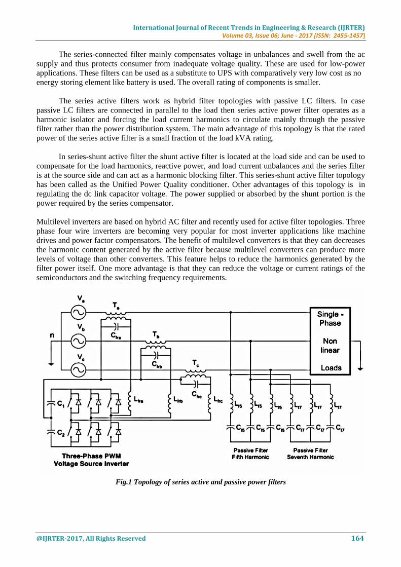
The series-connected filter mainly compensates voltage in unbalances and swell from the ac
supply and thus protects consumer from inadequate voltage quality. These are used for low-power
applications. These filters can be used as a substitute to UPS with comparatively very low cost as no
energy storing element like battery is used. The overall rating of components is smaller.
The series active filters work as hybrid filter topologies with passive LC filters. In case
passive LC filters are connected in parallel to the load then series active power filter operates as a
harmonic isolator and forcing the load current harmonics to circulate mainly through the passive
filter rather than the power distribution system. The main advantage of this topology is that the rated
power of the series active filter is a small fraction of the load kVA rating.
In series-shunt active filter the shunt active filter is located at the load side and can be used to
compensate for the load harmonics, reactive power, and load current unbalances and the series filter
is at the source side and can act as a harmonic blocking filter. This series-shunt active filter topology
has been called as the Unified Power Quality conditioner. Other advantages of this topology is in
regulating the dc link capacitor voltage. The power supplied or absorbed by the shunt portion is the
power required by the series compensator.
Multilevel inverters are based on hybrid AC filter and recently used for active filter topologies. Three
phase four wire inverters are becoming very popular for most inverter applications like machine
drives and power factor compensators. The benefit of multilevel converters is that they can decreases
the harmonic content generated by the active filter because multilevel converters can produce more
levels of voltage than other converters. This feature helps to reduce the harmonics generated by the
filter power itself. One more advantage is that they can reduce the voltage or current ratings of the
semiconductors and the switching frequency requirements.
Fig.1 Topology of series active and passive power filters

International Journal of Recent Trends in Engineering & Research (IJRTER) Volume 03, Issue 06; June - 2017 [ISSN: 2455-1457]
@IJRTER-2017, All Rights Reserved 165
III. ACTIVE POWER FILTERS AS SOURCE CONVERTERS
The active power filter topologies are often used as a voltage source converters. The topology
depicted in Figure 1, converts a dc voltage into an ac voltage by appropriately gating the power
semiconductor switches. A single pulse for each half cycle can be applied to synthesize an ac
voltage. For the purposes of dynamic performance, pulse width modulation is the most commonly
used in active power filter. PWM techniques are applied to control the VSI that chop the dc bus
voltage to produce an ac voltage of an arbitrary waveform. Voltage source converters are preferred
because have higher efficiency and lower initial cost than the current source converters [3, 4, 9].
They can also be expanded in parallel to increase their combined rating and their switching rate can
be increased if they are carefully controlled so that their individual switching times do not coincide.
Therefore, higher-order harmonics can be eliminated by using converters without increasing
individual converter switching rates. Because of nonlinear load current will have harmonics, so load
current will be the summation of fundamental and all other harmonics, all harmonics will be integer
multiple of fundamental frequency. Load current can be mathematically expressed as
𝑖𝐿(𝑡) = ∑ 𝑖𝑘sin(𝑘𝜔𝑡 + 𝜙𝑛)
∞
𝑘=1
And the instantaneous load is product of source voltage and load current, expressed as
𝑃𝐿(𝑡) = 𝑉𝑠(𝑡)× 𝑖𝐿(𝑡)
Fig.2 Principle of Shunt Active Power Filter
IV. MODELING & SIMULATION OF MICRO GRID DISTRIBUTION SYSTEM
The shunt active power filter model is developed and simulated in MATLAB with PWM based PI
controller. The complete active power filter system is composed mainly of three-phase source, a non-
linear load, a voltage source PWM converter, and a PI controller. All these components are modeled
separately, integrated and then solved to simulate the system. In modeling PI control scheme the
error signal is fed to PI controller. The output of PI controller has been considered as peak value of
the reference current. It is further multiplied by the unit sine vectors (usa, usb, and usc) in phase with
the source voltages to obtain the reference currents (isa *, isb *, and isc *). These reference currents
and actual currents are given to a hysteresis based, carrier less PWM current controller to generate
International Journal of Recent Trends in Engineering & Research (IJRTER) Volume 03, Issue 06; June - 2017 [ISSN: 2455-1457]
@IJRTER-2017, All Rights Reserved 166
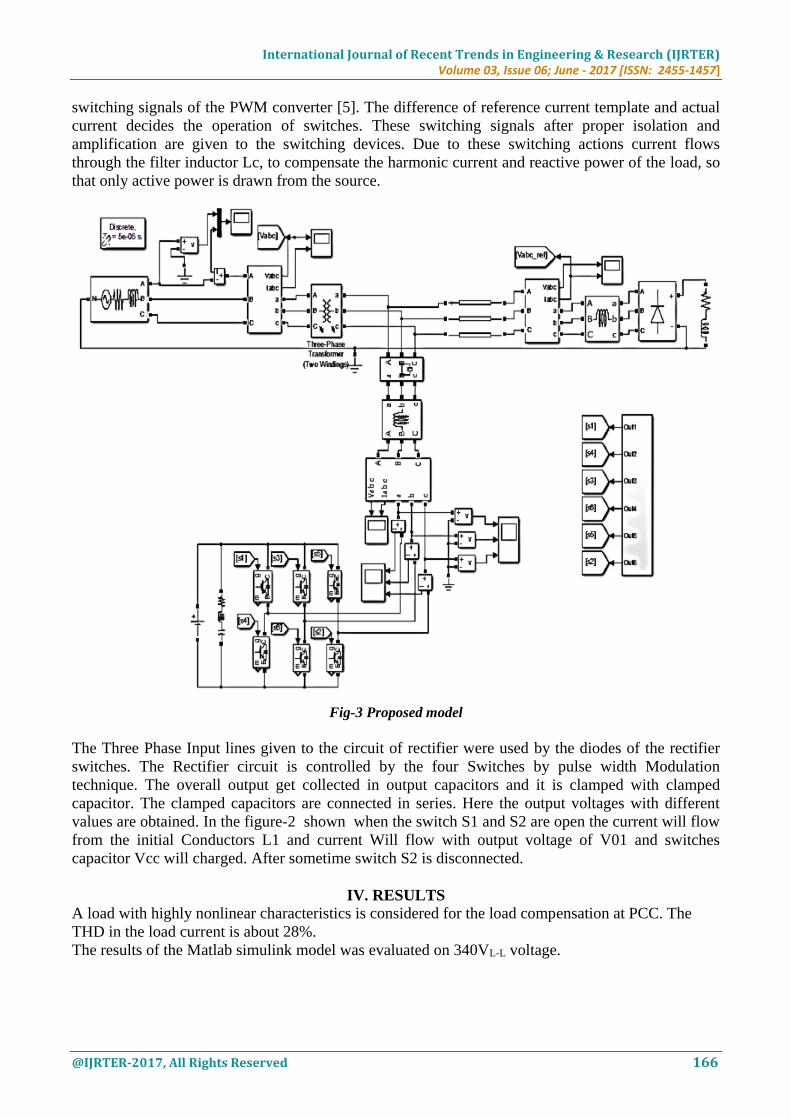
switching signals of the PWM converter [5]. The difference of reference current template and actual
current decides the operation of switches. These switching signals after proper isolation and
amplification are given to the switching devices. Due to these switching actions current flows
through the filter inductor Lc, to compensate the harmonic current and reactive power of the load, so
that only active power is drawn from the source.
Fig-3 Proposed model
The Three Phase Input lines given to the circuit of rectifier were used by the diodes of the rectifier
switches. The Rectifier circuit is controlled by the four Switches by pulse width Modulation
technique. The overall output get collected in output capacitors and it is clamped with clamped
capacitor. The clamped capacitors are connected in series. Here the output voltages with different
values are obtained. In the figure-2 shown when the switch S1 and S2 are open the current will flow
from the initial Conductors L1 and current Will flow with output voltage of V01 and switches
capacitor Vcc will charged. After sometime switch S2 is disconnected.
IV. RESULTS
A load with highly nonlinear characteristics is considered for the load compensation at PCC. The
THD in the load current is about 28%.
The results of the Matlab simulink model was evaluated on 340VL-L voltage.

International Journal of Recent Trends in Engineering & Research (IJRTER) Volume 03, Issue 06; June - 2017 [ISSN: 2455-1457]
@IJRTER-2017, All Rights Reserved 167
Fig – 4 Source Voltage waveforms of the system
The compensator is switched ON at t = 0.005s and the integral time square error performance index
is used as coefficients of the PI controller. The optimum values of Kp and Ki are found to be 0.05
and 1, respectively, which corresponds to the minimum value of ITSE. Compensating currents of PI
controllers are shown in figures 5.
Fig – 5 Source Current when compensator is not connected
.
Fig.6 Output Voltage Wave of APF
Fig.7 Output Current Wave of APF
International Journal of Recent Trends in Engineering & Research (IJRTER) Volume 03, Issue 06; June - 2017 [ISSN: 2455-1457]
@IJRTER-2017, All Rights Reserved 168
From the wave forms it is clear that harmonic distortion is reduced after connecting compensator.
The system parameters selected for simulation study are given in table 2 and 3. Figures 6-7 shows
the simulation results of the implemented system with PI controller. The source voltage waveform of
the reference phase only is shown in figure 4. A diode rectifier with R-L load is taken as non-linear
load. The THD of the load current is 24.90%. The optimum values (Kp and Ki) are found to be 0.05
and 1 respectively.
V. CONCLUSION
In the paper, PI controller based shunt active power filter simulated in MATLAB are implemented
for harmonic and reactive power compensation of the non-linear load at PCC. It is found from the
simulation results that shunt active power filter improves power quality of the distribution system by
eliminating harmonics and reactive power compensation of non-linear load. It in turn makes the load
current sinusoidal and in phase with the source voltage. The THD of the source current is below 5%
REFERENCES 1. Ning-Yi Dai, Man-Chung Wong, and Ying-Duo Han, Seni, “Application of a Three-level NPC Inverter as a
Three-Phase Four-Wire Power Quality Compensator by Generalized 3DSVM” IEEE Transactions On Power
Electronics, Vol. 21, No. 2, March 2006.
2. P. Salmeron, J. C. Montano, J. R. Vazquez, J. Prieto, and A. Perez, “Compensation in Nonsinusoidal,
Unbalanced Three-Phase Four- Wire Systems With Active Power-Line Conditioner” IEEE Transactions On
Power Delivery, Vol. 19, No. 4, October 2004
3. S. Orts-Grau, F. J. Gimeno-Sales, A. Abellan-Garcia, S. Segui- Chilet, and J. C. Alfonso-Gil, “Improved Shunt
Active Power Compensator for IEEE Standard 1459 Compliance” IEEE Transactions on Power Delivery, Vol.
25, No. 4, October 2010
4. Reyes S. Herrera and Patricio Salmeron, “Instantaneous Reactive Power Theory: A Comparative evaluation of
Different Formulations” IEEE Transactions On Power Delivery, Vol. 22, No. 1, January 2007
5. Reyes S. Herrera, Patricio Salmeron, and Hyosung Kim “Instantaneous Reactive Power Theory Applied to
Active Power Filter Compensation: Different Approaches, Assessment, and Experimental Results” IEEE
Transactions On Industrial Electronics, Vol. 55, No. 1, Jan. 2008
6. Yunwei Li, D. Mahinda Vilathgamuwa and Poh Chiang Loh “Microgrid Power Quality Enhancement Using a
Three-Phase Four-Wire Grid-Interfacing Compensator” IEEE Transactions On Industry Applications, Vol. 41,
No. 6, November/December 2005
7. A.Elmitwally, SAbdelkader and M.EI-Kateb, “Neural network controlled three-phase four-wire shunt active
power filter” IEE Power Generation & transmission Vol. 147, N0.2 March 2000
8. J. A. Barrado, R. Grino and H. Valderrama-Blavi, “Power-Quality Improvement of a Stand- Alone Induction
Generator Using a STATCOM With Battery Energy Storage System” IEEE Transactions On Power Delivery,
Vol. 25, No. 4, October 2010
9. Rade M. Ciric, Antonio Padilha Feltrin, and Luis F. Ochoa, “Power Flow in Four-Wire Distribution Networks—
General Approach” IEEE Transactions On Power Systems , Vol. 18, No. 4, November 2003
10. C.-S. Lam, M.-C. Wong Y.-D. Han, “Hysteresis current control of hybrid active power filters” Published in IET
Power Electronics, doi: 10.1049/iet-pel.2011.0300
11. Vinod Khadkikar, “Enhancing Electric Power Quality Using UPQC:A Comprehensive Overview” IEEE
Transactions on Power Electronics, Vol. 27, No. 5, May 2012