modeling of photonic crystal fiber with air holes sealed at the fiber end and its application to...
TRANSCRIPT

Modeling of photonic crystal fiber with air holes sealed at the fiber end and its application to
fluorescent light collection efficiency enhancement
Jianjun Ma and Wojtek J. Bock
Centre de recherche en photonique, Département d’informatique et d’ingénierie, Université du Québec en Outaouais,
P.O. Box 1250, Station B, Gatineau, Québec J8X 3X7, Canada, [email protected], [email protected]
Abstract: A model of large core and multimode photonic crystal fiber (PCF) with sealed air holes at its end face is proposed for the first time. The model indicates that this PCF can be replaced by another equivalent fiber with complete holes at a new end-face position. Instead of a segment of glass rod between the old and new end faces, light rays travel in a virtual medium with the loss rating of pure glass but the refractive index of the immersion medium. For a two-fiber structure, this segment of pure glass has the capability of enhancing the light collection efficiency, which is investigated using a specifically designed fiber probe and fluorescent samples with different concentrations.
©2005 Optical Society of America
OCIS codes: (060.2270) Fiber Characterization; (060.2370) Fiber Optics Sensors; (999.999) Photonic Crystal Fiber; (300.6280) Spectroscopy, Fluorescence and Luminescence
References and Links
1. J.C. Knight, T.A. Birks, P.St.J. Russell, and D. M. Atkin, "All-silica single-mode optical fiber with photoniccrystal cladding," Opt. Lett. 21, 1547-1549 (1996).
2. T.A. Birks, J.C. Knight, and P.St.J. Russell, "Endlessly single-mode photonic crystal fiber," Opt. Lett. 22, 961-963 (1997).
3. J.C. Knight, J. Broeng, T.A. Birks, and P. S. J. Russel, "Photonic band-gap guidance in optical fibers," Science 282, 1476 - 1478 (1998).
4. N.A. Mortensen, M.D. Nielsen, J.R. Folkenberg, A. Petersson, and H.R. Simonsen, "Improved large-mode-area endlessly single-mode photonic crystal fibers," Opt. Lett. 24, 46-48 (1999).
5. J. Limpert, T. Schreiber, S. Nolte, H. Zellmer, T. Tunnermann, R. Iliew, F. Lederer, J. Broeng, G. Vienne, A. Petersson, and C. Jakobsen, "High-power air-clad large-mode-area photonic crystal fiber laser," Opt. Express 11, 818-823 (2003),
http://www.opticsexpress.org/abstract.cfm?URI=OPEX-11-7-818. 6. T. M. Monro, D. J. Richardson, N. G. R. Broderick and P. J. Bennett, "Holey optical fibers: an
efficient modal model," J. Lightwave Technol. 17, 1093-1102 (1999). 7. Multimode Untra High NA Photonic Crystal fiber-MM⋅HN⋅200, (MM⋅HNA⋅200 Rev 2.0 Oct. 2003),
http://www.crystal-fibre.com/datasheets/MM-HNA-200.pdf. 8. Thomas F. Cooney, H. Trey Skinner and S. M. Angel, "Comparative study of some fiber-optic remote
raman probe designs. Part II: tests of single-fiber, lensed and flat-and bevel-tip multi-fiber probes," Appl. Spectrosc. 50, 849-860 (1996).
9. P. Plaza, Nguyen Quy Dao, M. Jouan, H. Fevrier, and H. Saisse, "Simulation et optimization des capteurs à fibres optiques adjacentes," Appl. Opt. 25, 3448-3454 (1986).
10. Scott D. Schwab and Richard L. McCreery, "Versatile, efficient Raman sampling with fiber optics," Anal. Chem. 56, 2199-2204 (1984).
(C) 2005 OSA 4 April 2005 / Vol. 13, No. 7 / OPTICS EXPRESS 2385#6746 - $15.00 US Received 3 March 2005; revised 16 March 2005; accepted 16 March 2005

11. J. Ma, W. J. Bock, "Light coupling model for a photonic crystal fiber with air holes collapsed at the fiber end," in Photonics North 2004: Photonic Applications in Telecommunications, Sensors, Software, and Lasers, J. Armitage, R. Lessard, G. Lampropoulos, eds., Proc. SPIE Vol. 5579, 93-98 (2004)
12. J. J. Larsen and G. Vienne, "Side pumping of double-clad photonic crystal fibers," Opt. Lett. 29, 436 - 438 (2004).
13. A. D. Yablon and R. T. Bise, "Low-loss high-strength microstructured fiber fusion splices using GRIN fiber lenses," IEEE Photonics Technol. Lett. 17, 118-120 (2005).
14. E. C. Mägi, H. C. Nguyen, and B. J. Eggleton, "Air-hole collapse and mode transitions in microstructured fiber photonic wires," Opt. Express 13, 453-459 (2005), http://www.opticsexpress.org/abstract.cfm?URI=OPEX-13-2-453
15. G. Keiser, Optical fiber communications (McGraw-Hill Higher Education, third edition, 2000), Chap. 2. 16. Z. Zhu and M. C. Yappert, "Determination of the effective depth and equivalent pathlength for a single-
fiber fluorometric sensor," Appl. Spectrosc. 46, 912-918 (1992). 17. Z. Zhu and M. C. Yappert, "Determination of the effective depth for double-fiber fluorometric sensors,"
Appl. Spectrosc. 46, 919-924 (1992). 18. USB2000 Miniature Fiber Optic Spectrometer (Ocean Optics, 2005),
http://www.oceanoptics.com/products/usb2000.asp
1. Introduction
Photonic crystal fiber (PCF) is a new type of optical waveguide in the optical fiber family. Both core and cladding materials of PCFs, unlike conventional fibers, can be formed from the same pure silica material. For the index-guiding type of PCF, the lower index of cladding is generated by air holes surrounding the solid core [1,2]. Another type of PCF operates through photonic bandgap (PBG) effects, which permit the light to travel in a low-index hollow core surrounded by a periodic structure of air holes [3]. Promising new applications that would be impossible for conventional fiber have been demonstrated for PCFs such as endless single-mode operation in a very-large-core area [2,4], high power fiber laser [5] and manageable dispersion properties [6]. Moreover, by an appropriate design of the air-hole structure, a very high numerical aperture (NA) can be achieved. One such fiber, MM-HN-200 PCF from Crystal-Fiber A/S, is shown in Fig. 1(a) and (b), which is a multimode fiber with 200/335 µm core/cladding diameter, a single layer of air holes and a high NA of 0.64 [7].
It is well known that the combination of a low signal attenuation over long-distance
transmission plus a higher NA for enhancing light-collection efficiency is highly desirable in many fiber sensing applications [8-10]. This is usually difficult to achieve with a conventional silica optical fiber or a high-NA plastic fiber. Furthermore, for a two-fiber probe, a higher NA is also beneficial to the increase of the overlap volume and the reduction of dead zone between the illuminating and receiving fiber. A particularly interesting example is fiber-optic chemical or biological sensing for remote Raman scattering or fluorescence measurement.
(a) (b)
(c) (d) (e)
Fig. 1. MM-HN-200 PCF from Crystal-Fiber A/S. (a). end face with complete air holes; (b). side view of (a); (c). side view of PCF having a segment of sealed air holes in the fiber end; (d). end face of (c) with light intensity distributed across the entire surface because of the missing air holes; (e). end face view of (d) obtained by focusing the camera on a deeper cross-section inside the PCF.
(C) 2005 OSA 4 April 2005 / Vol. 13, No. 7 / OPTICS EXPRESS 2386#6746 - $15.00 US Received 3 March 2005; revised 16 March 2005; accepted 16 March 2005

Both Raman scattering and fluorescent signals are usually weak and dispersed in all directions. A PCF with the advantages mentioned above is a good candidate for collecting these signals at higher efficiency while delivering the signal to the remote central monitoring room at a significantly low loss.
However, the air holes surrounding the fiber core along the fiber will be easily contaminated. Especially for chemical or biological sensing, the fiber needs to be in contact with fluid. The small hollow air holes will uptake the fluid by capillary action and change the optical properties of the fiber. To alleviate this, a simple and low-cost approach is to completely seal the air holes over a certain length of the fiber end. Instead of a waveguide, this segment of fiber becomes a pure silica glass rod placed in front of a PCF, which has been investigated in our initial study [11]. This approach has also been presented for other applications such as side pumping of double-clad PCFs [12], fiber splicing with GRIN fiber lenses [13] and mode transition through microstructured fiber photonic wires [14]. The researchers in those studies sealed the air holes in the middle part of the fiber to achieve the desired optical effects and focused on single-mode PCFs. To our knowledge, theoretical investigation of a high NA and large-core PCF with a collapsed end face has not been presented and will be discussed in this paper. Particularly, for the two-fiber probe, we will use this model to investigate the fluorescent light collection efficiency enhancement introduced by this fused segment.
2. Modeling of PCF with air holes sealed at the end face.
Figure 2 shows the model of PCF with core and cladding diameters of d and D, respectively. Ray optics is applied through our discussion, as the PCF presented possesses a large core size meeting the condition d >> λ [15]. The PCF is surrounded by a homogeneous immersion medium with a refractive index of 2n . The refractive index of the glass material of PCF is 1n . A Cartesian coordinate system is established with its origin O(0, 0) at the center of the glass-immersion medium end face (the plane A′-B′). A fiber splicer is used to completely seal the end-face air holes to the position y (the plane D-G). Obviously, instead of being guided in
the fiber core, the light between the plane A′-B′ and the plane D-G will propagate by following a straight line. The intuitive proof is shown in Fig. 1(c), (d) and (e) which show the side view and end face of the PCF after the fusion process. Figure 1(d) indicates that when a light with a larger incident angle is launched into this PCF, at the exit of the fiber the light distributes over the entire end face because of the missing air holes. Figure 1 (e) is the picture obtained by focusing the camera on a deeper cross-section with surrounding air holes where the light is strictly trapped inside the core.
The light collected by the end-face-sealed PCF will vary depending on the length of the sealed segment and the refractive index of the immersion medium. An equivalent fiber with complete air holes could be used as a replacement to simplify the investigation of the end-face-sealed PCF. The vertical dotted lines between the planes C-H and D-G stand for the virtual cladding holes of this equivalent fiber. An important change is that the glass material in front of the equivalent fiber (between the planes A′-B′ and C-H) is replaced by a virtual medium with the loss ratio of pure glass but the refractive index of immersion medium 2n . As
a result, for the real PCF, light rays AA′, BB′ and RS will reach D, G and F following Snell’s law. For its equivalent fiber, however, these three rays will reach C, H and E following the straight lines. From Snell’s law, the end-face position of this equivalent fiber eqy (the plane C-
H) is given by:
221
222
Γ−Γ−=
n
nyyeq (1)
(C) 2005 OSA 4 April 2005 / Vol. 13, No. 7 / OPTICS EXPRESS 2387#6746 - $15.00 US Received 3 March 2005; revised 16 March 2005; accepted 16 March 2005

where 22 sin θ=Γ n . For a fixed immersion medium, factor Γ will alter the end-face position (the plane C-H)
by adjusting the angle 2θ of the incident light AA′. The angle 2θ could be determined by the NA of the PCF or the light source, or could be set to any desired angle. Obviously, light with an incident angle of 2θ and 0=θ i will reach the same position along x axis for both real (start to guide the light from the plane D-G) and equivalent fibers (start to guide the light from the plane C-H) in Fig. 2. For any other incident angle iθ (see the ray RS), the points E and F
will have different x values. This is described as a position difference exx −=δ which is
expressed as:
)sincos
1(sin
222
21
222
1
222
iii
nn
n
n
ny
θ−−
Γ−Γ−
θθ=δ (2)
The error factor y/δ describes the accuracy of the model. For a PCF with NA=0.64, Fig.
3 (a) and (b) present the numerical results of the error distributions y/δ for different incident
angles of iθ in air and liquid immersion media ( 46.11 =n and 33.12 =n are assumed), respectively. The results show that if the maximum incident angle determined by NA is chosen to identify eqy , that is, NA=Γ , the maximum error max)/( yδ will be somewhere
between 0 and the maximum incident angle. It is indicated in Fig. 3(a) and (b) that when NA=Γ is selected, even max)/( yδ will be only 3% and 0.5% for air and liquid immersion
media, respectively. If eqy is determined by the maximum incident angle meeting the
condition of NA<Γ , in a certain range of incident angles max)/( yδ can be quite small. However, it will increase quickly when the angle of incident light becomes very large but will not exceed 8% and 1.5% for the air and liquid immersion media, respectively. The value of
max)/( yδ will be large through the entire range of incident angles if NA>Γ is chosen to
y
n1 y
yeq θ1
θ2 n2
Air holes d
Fiber core
A
A′ O(0,0) x
δ
D
θt
θi
E (xe,ye)
F(x,y) End face of equivalent PCF
D
C H
G
B
B′
R
S
Fig. 2. The PCF end with a segment of sealed air holes (between the plane A′-B′ and the plane D-G) and its equivalent PCF with complete air holes (end face on the plane C-H). Here, y stands for the sealed length; yeq is the end-face position of the equivalent fiber.
(C) 2005 OSA 4 April 2005 / Vol. 13, No. 7 / OPTICS EXPRESS 2388#6746 - $15.00 US Received 3 March 2005; revised 16 March 2005; accepted 16 March 2005

calculate eqy . To assure that max)/( yδ is reasonably small over the entire range of incident
angles, we propose to choose NA=Γ to determine eqy , which is assumed throughout our
later discussions. Another aspect to be highlighted is that this model is accurate for a fiber with a larger
core size and/or a shorter fused segment. It will be especially efficient for the liquid immersion medium. Looking again at the rays SF and SE in Fig. 2, it is easy to see that for certain incident rays near the core-cladding boundary, if the collapsed segment y is long enough, the light will no longer be able to hit the real fiber core (start from plane D-G) even if its equivalent PCF segment still guides these rays (start from plane C-H). For the worst case, the efficient fiber core diameter ed for the equivalent fiber could be modified as:
max2δ−= dde (3)
Where maxδ is determined by the maximum value of y/δ calculated from Eq. (2).
Assuming the light power is uniformly distributed in the fiber core area, rI and
eqI represent the power received by the real fiber and the equivalent fiber, respectively. Their
ratio is expressed as:
2
max
2
21 ⎟⎟⎠
⎞⎜⎜⎝
⎛⎟⎠
⎞⎜⎝
⎛ δ−=⎟
⎠
⎞⎜⎝
⎛>dd
d
I
I e
eq
r (4)
For a MM-HN-200 PCF in the air immersion medium, with the air holes sealed
to my µ= 135 , the calculation shows that %1.2)/( max =δ d and %91>eqr II ; for a shorter
length of my µ= 50 , a result of %77.0)/( max =δ d and %97>eqr II is achieved. For the
case of a small-core fiber, for instance md µ= 30 , 64.0=NA and my µ= 135 , we will get
only %53>eqr II ; to have the same ratio of %97>eqr II , my µ< 31 must be met. For a
liquid immersion medium and my µ= 135 , we can get %34.0)/( max =δ d and %98>eqr II .
So this model possesses much higher accuracy when the PCF is used for liquid samples. It also deserves to highlight that in reality the fiber core size has its tolerance. For example, for
my µ= 135 fused segment, Fig. 3(a) and (b) will give mµ=δ 4max and mµ=δ 7.0max for
64.0=Γ in air and liquid immersion media, respectively. The results are comparable with the MM-HN-200 PCF core size tolerance mµ± 0.3200 [7]. This means no observable light
0.0%
0.3%
0.5%
0.8%
1.0%
1.3%
1.5%
-30 -20 -10 0 10 20 30
Incident angle θi
0%
2%
4%
6%
8%
10%
-40 -30 -20 -10 0 10 20 30 40
Incident angle θi
Fig. 3. For different Γ, numerical results of δ/y vs. different incident angles θi from Eq. (2): (a) when the PCF is in the air immersion medium; (b) when the PCF is in the liquid immersion medium.
(a)
Γ=0.8
Γ=0.7
Γ=0.64
Γ=0.5
Γ=0.2
Γ=0.4
δ/y δ/y
Γ=0.8
Γ=0.7
Γ=0.64
Γ=0.5
Γ=0.2
Γ=0.4
(b)
(C) 2005 OSA 4 April 2005 / Vol. 13, No. 7 / OPTICS EXPRESS 2389#6746 - $15.00 US Received 3 March 2005; revised 16 March 2005; accepted 16 March 2005

collection difference will be found between the real fiber and its equivalent fiber for this length of fused segment or less. In other words, this model has a fairly good precision.
It is also important to know to what extent the NA factor will affect eqy . This is
demonstrated in Fig. 4 for both air and liquid immersion media. In a liquid immersion medium, a longer length of eqy is always expected (20% ~ 30% greater than the length in the
air medium for the range of 0.22 < NA < 0.64, a typical range for conventional multimode fibers). When the NA is very high (NA > 0.8), eqy in the air immersion medium will decrease
rapidly, which means a greater light-collection capability. This is coherent with the intuitive expectation. Figure 4 also shows that in the liquid medium, there is only 8.6% change for the entire calculated range of NA (from 0.22 to 1). This value becomes 69% for the air medium. This means that in the liquid immersion medium, the NA of the PCF has less effect on the change of eqy .
3. Application of the PCF model to a two-fiber probe to enhance the efficiency of fluorescent light collection
As shown in Fig. 5, to compare the fluorescent light collection efficiency of PCF fiber with and without sealed air holes in the end face, two identical PCFs (marked as PCF-1 and PCF-2, respectively) are symmetrically attached to a multimode illuminating fiber. Although physically the end face of PCF-2 is located on the same plane as two other fibers from the developed model, its light collection capability is equal to that of another PCF with identical core/cladding size and NA (equivalent PCF). However, this equivalent PCF has complete air holes. Its end face is placed at a distance of eqy from the plane B-B′. The medium within the
distance eqy (marked as V ′ which is enclosed inside a dotted rectangle) will have the same
refractive index n as the medium before the plane B-B′. Obviously, in the volume V ′ , the attenuation is associated with the pure glass, which is considered as zero. This is especially important for an immersion medium with a significant attenuation level. Figure 5 also indicates the overlap volumes of PCF-1 and PCF-2, respectively. 10−V and 20−V are both the
same size, but 20−V will receive more excitation light and thus more fluorescent signal because it is close to the axis of the illuminating fiber where usually most of excitation energy is located. Light rays from 10−V and 20−V will travel the same distance to the end face of PCF-1
and the real end face of PCF-2 (both on the plane B-B′) and will thus experience the same loss caused by the immersion medium. The light rays from the end face of PCF-2 will pass an
0
0.2
0.4
0.6
0.8
1
0.2 0.4 0.6 0.8 1
NA
y eq/y
Air medium
Liquid medium
Fig. 4. The end-face position of the equivalent PCF in the air and liquid immersion media vs. NA.
(C) 2005 OSA 4 April 2005 / Vol. 13, No. 7 / OPTICS EXPRESS 2390#6746 - $15.00 US Received 3 March 2005; revised 16 March 2005; accepted 16 March 2005
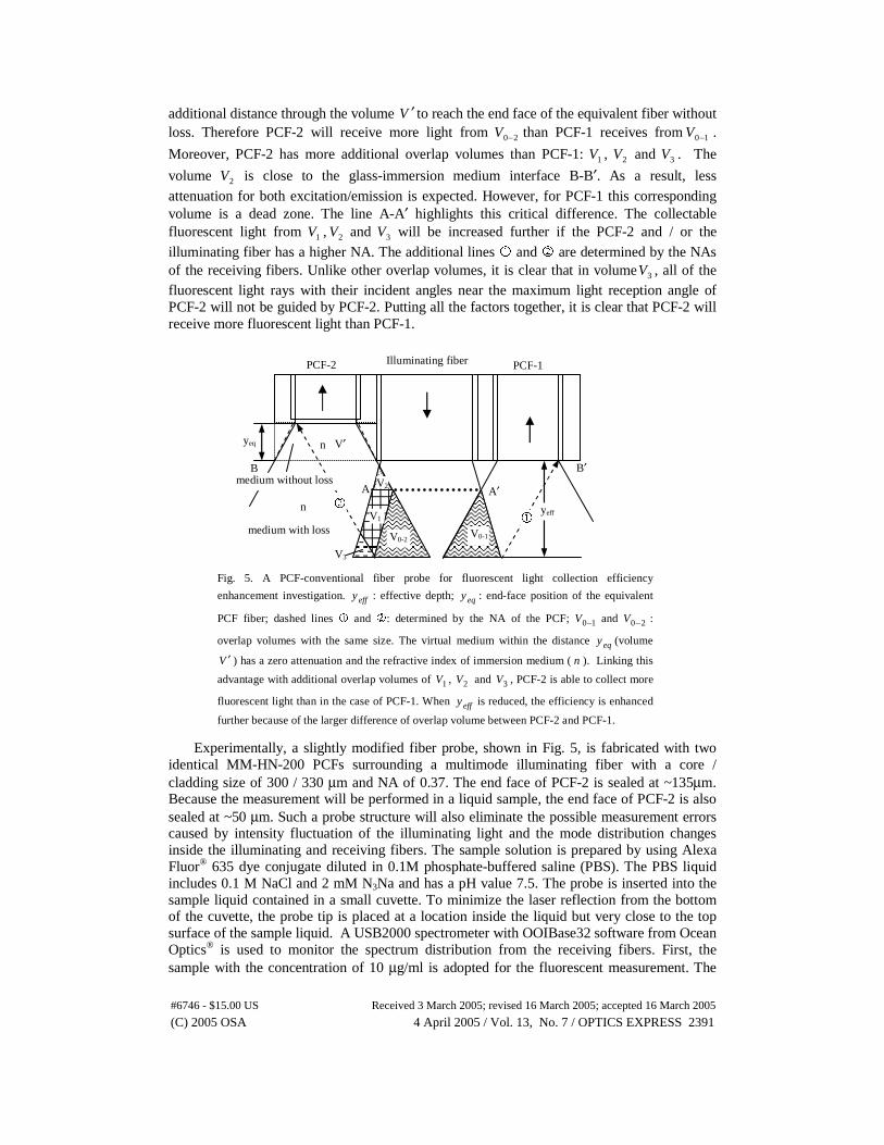
additional distance through the volume V ′ to reach the end face of the equivalent fiber without loss. Therefore PCF-2 will receive more light from 20−V than PCF-1 receives from 10−V .
Moreover, PCF-2 has more additional overlap volumes than PCF-1: 1V , 2V and 3V . The
volume 2V is close to the glass-immersion medium interface B-B′. As a result, less attenuation for both excitation/emission is expected. However, for PCF-1 this corresponding volume is a dead zone. The line A-A′ highlights this critical difference. The collectable fluorescent light from 1V , 2V and 3V will be increased further if the PCF-2 and / or the illuminating fiber has a higher NA. The additional lines � and � are determined by the NAs of the receiving fibers. Unlike other overlap volumes, it is clear that in volume 3V , all of the fluorescent light rays with their incident angles near the maximum light reception angle of PCF-2 will not be guided by PCF-2. Putting all the factors together, it is clear that PCF-2 will receive more fluorescent light than PCF-1.
Experimentally, a slightly modified fiber probe, shown in Fig. 5, is fabricated with two
identical MM-HN-200 PCFs surrounding a multimode illuminating fiber with a core / cladding size of 300 / 330 µm and NA of 0.37. The end face of PCF-2 is sealed at ~135µm. Because the measurement will be performed in a liquid sample, the end face of PCF-2 is also sealed at ~50 µm. Such a probe structure will also eliminate the possible measurement errors caused by intensity fluctuation of the illuminating light and the mode distribution changes inside the illuminating and receiving fibers. The sample solution is prepared by using Alexa Fluor® 635 dye conjugate diluted in 0.1M phosphate-buffered saline (PBS). The PBS liquid includes 0.1 M NaCl and 2 mM N3Na and has a pH value 7.5. The probe is inserted into the sample liquid contained in a small cuvette. To minimize the laser reflection from the bottom of the cuvette, the probe tip is placed at a location inside the liquid but very close to the top surface of the sample liquid. A USB2000 spectrometer with OOIBase32 software from Ocean Optics® is used to monitor the spectrum distribution from the receiving fibers. First, the sample with the concentration of 10 µg/ml is adopted for the fluorescent measurement. The
Fig. 5. A PCF-conventional fiber probe for fluorescent light collection efficiency
enhancement investigation. effy : effective depth; eqy : end-face position of the equivalent
PCF fiber; dashed lines � and �: determined by the NA of the PCF; 10−V and 20−V :
overlap volumes with the same size. The virtual medium within the distance eqy (volume
V ′ ) has a zero attenuation and the refractive index of immersion medium ( n ). Linking this
advantage with additional overlap volumes of 1V , 2V and 3V , PCF-2 is able to collect more
fluorescent light than in the case of PCF-1. When effy is reduced, the efficiency is enhanced
further because of the larger difference of overlap volume between PCF-2 and PCF-1.
V1
V2
V3
V1 medium with loss
medium without loss
PCF-2 Illuminating fiber
A
B
V0-1
PCF-1
A′
B′
yeq n
n
V′
yeff �
�
V0-2
(C) 2005 OSA 4 April 2005 / Vol. 13, No. 7 / OPTICS EXPRESS 2391#6746 - $15.00 US Received 3 March 2005; revised 16 March 2005; accepted 16 March 2005
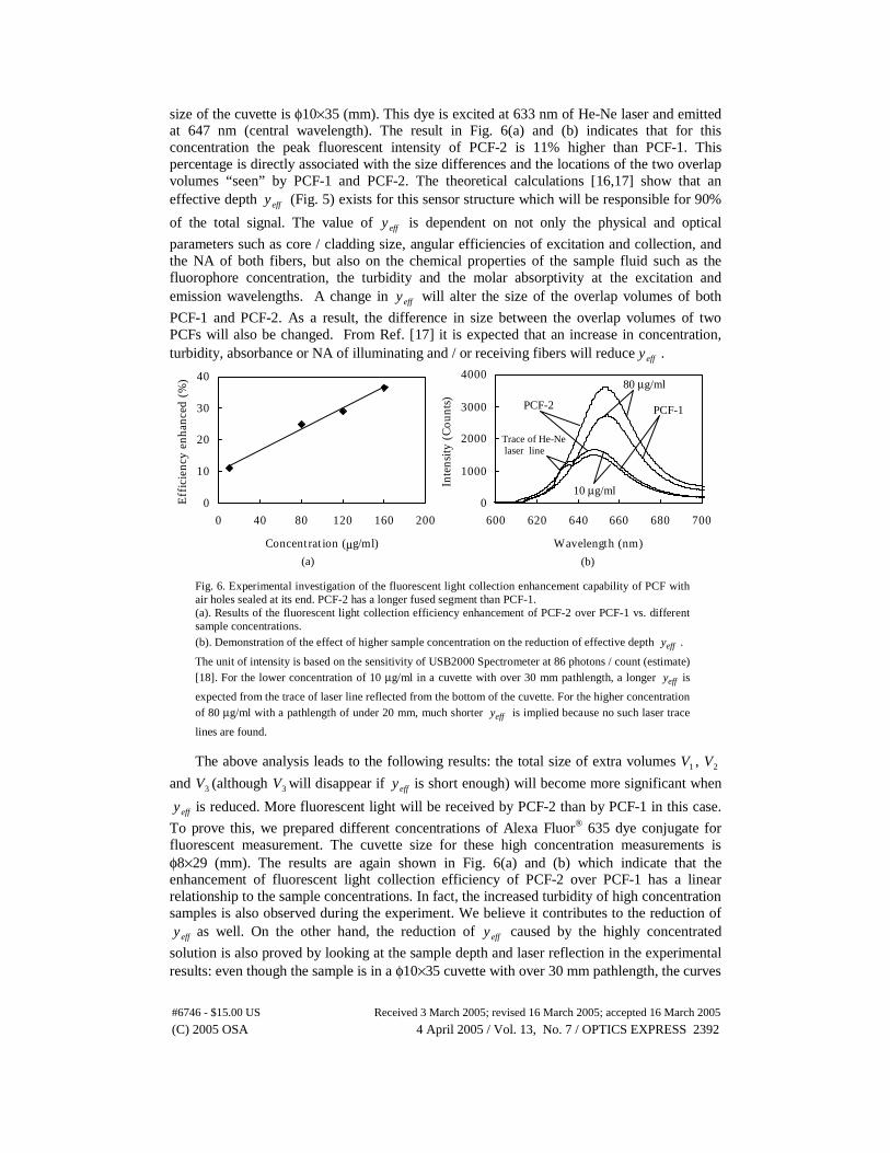
size of the cuvette is φ10×35 (mm). This dye is excited at 633 nm of He-Ne laser and emitted at 647 nm (central wavelength). The result in Fig. 6(a) and (b) indicates that for this concentration the peak fluorescent intensity of PCF-2 is 11% higher than PCF-1. This percentage is directly associated with the size differences and the locations of the two overlap volumes “seen” by PCF-1 and PCF-2. The theoretical calculations [16,17] show that an effective depth effy (Fig. 5) exists for this sensor structure which will be responsible for 90%
of the total signal. The value of effy is dependent on not only the physical and optical
parameters such as core / cladding size, angular efficiencies of excitation and collection, and the NA of both fibers, but also on the chemical properties of the sample fluid such as the fluorophore concentration, the turbidity and the molar absorptivity at the excitation and emission wavelengths. A change in effy will alter the size of the overlap volumes of both
PCF-1 and PCF-2. As a result, the difference in size between the overlap volumes of two PCFs will also be changed. From Ref. [17] it is expected that an increase in concentration, turbidity, absorbance or NA of illuminating and / or receiving fibers will reduce effy .
The above analysis leads to the following results: the total size of extra volumes 1V , 2V
and 3V (although 3V will disappear if effy is short enough) will become more significant when
effy is reduced. More fluorescent light will be received by PCF-2 than by PCF-1 in this case.
To prove this, we prepared different concentrations of Alexa Fluor® 635 dye conjugate for fluorescent measurement. The cuvette size for these high concentration measurements is φ8×29 (mm). The results are again shown in Fig. 6(a) and (b) which indicate that the enhancement of fluorescent light collection efficiency of PCF-2 over PCF-1 has a linear relationship to the sample concentrations. In fact, the increased turbidity of high concentration samples is also observed during the experiment. We believe it contributes to the reduction of
effy as well. On the other hand, the reduction of effy caused by the highly concentrated
solution is also proved by looking at the sample depth and laser reflection in the experimental results: even though the sample is in a φ10×35 cuvette with over 30 mm pathlength, the curves
0
10
20
30
40
0 40 80 120 160 200
Concentrat ion (µg/ml)
Eff
icie
ncy
enha
nced
(%
)
0
1000
2000
3000
4000
600 620 640 660 680 700
Wavelength (nm)
Inte
nsity
(C
ount
s)
Fig. 6. Experimental investigation of the fluorescent light collection enhancement capability of PCF with air holes sealed at its end. PCF-2 has a longer fused segment than PCF-1. (a). Results of the fluorescent light collection efficiency enhancement of PCF-2 over PCF-1 vs. different sample concentrations. (b). Demonstration of the effect of higher sample concentration on the reduction of effective depth effy .
The unit of intensity is based on the sensitivity of USB2000 Spectrometer at 86 photons / count (estimate) [18]. For the lower concentration of 10 µg/ml in a cuvette with over 30 mm pathlength, a longer effy is
expected from the trace of laser line reflected from the bottom of the cuvette. For the higher concentration of 80 µg/ml with a pathlength of under 20 mm, much shorter effy is implied because no such laser trace
lines are found.
(a) (b)
80 µg/ml
10 µg/ml
Trace of He-Ne laser line
PCF-1 PCF-2
(C) 2005 OSA 4 April 2005 / Vol. 13, No. 7 / OPTICS EXPRESS 2392#6746 - $15.00 US Received 3 March 2005; revised 16 March 2005; accepted 16 March 2005

corresponding to 10 µg/ml solution in Fig. 6(b) reveal the obvious trace of the He-Ne laser line at 633 nm reflected from the cuvette bottom. The 80 µg/ml sample is in a cuvette with a size of φ8×29 and a fluid level less than 20 mm. No laser line traces are shown in Fig.6(b) for this concentration. This evidence shows that the high concentration sample has much less effective depth effy than the low concentration sample. It again confirms that the high
concentration will reduce the effective depth and enhance the light collection efficiency for this probe structure.
4. Conclusions
In conclusion, a model of large-core and multimode PCF with a segment of sealed air holes at the fiber end is proposed and demonstrated. The theoretical analysis shows that this model is more accurate for a PCF with a larger core and / or a shorter end face with sealed air holes. This model is especially accurate in a liquid immersion medium. Its application to enhance the signal collection efficiency of a fiber-optic fluorescent sensor is particularly investigated. This capability is achieved in a different way than would be used with conventional fibers. The size and extreme low-loss nature of the pure glass in front of the PCF contribute to this enhancement by increasing the overlap volume between the illuminating and receiving fibers. Furthermore, the dead zone right before the illuminating and receiving fiber could also be partly converted to overlap volume. This zone is more valuable when the effective depth is reduced enormously, which may be introduced by chemical property changes in the measured samples. This model provides a useful tool for analyzing the light collection capability of a PCF in fiber-sensing applications, especially in chemical and biological measurements in liquid samples.
Acknowledgments
The authors gratefully acknowledge the support of this work from Natural Sciences and Engineering Research Council of Canada. The authors also thank Dr. Ewa Dabek of Environmental Technology Centre, Ottawa, Ontario, Canada for the help during our chemical experiments.
(C) 2005 OSA 4 April 2005 / Vol. 13, No. 7 / OPTICS EXPRESS 2393#6746 - $15.00 US Received 3 March 2005; revised 16 March 2005; accepted 16 March 2005