modeling of heat and mass transfer and absorption...
TRANSCRIPT

Chapter 7
Modeling of Heat and Mass Transferand Absorption-Condensation Dustand Gas Cleaning in Jet Scrubbers
M. I. Shilyaev and E. M. Khromova
Additional information is available at the end of the chapter
http://dx.doi.org/10.5772/53094
1. Introduction
The process of complex cleaning of gases, injected into the atmosphere, for instance, by ther‐mal power plants, metallurgical, chemical or other industrial enterprises, from dust andharmful gaseous admixtures by means of their irrigation by wash liquids (water or speciallyselected water solutions) is considered. This process can be implemented in gas pipes orgas-cleaning apparatuses (direct flow or counter flow jet scrubbers) [1]. The process of gascleaning from dust and gas admixtures is carried out in the following manner. The fluid dis‐persed by jets is introduced into the dust-vapor-gas flow in the form of droplets, interactswith it, and under nonisothermal conditions the increased moisture content leads to inten‐sive condensation of liquid vapors on particles, their significant enlargement and efficientabsorption of liquid droplets due to collisions of the latter with particles [2]. Simultaneously,the liquid droplets and condensate on particles absorb harmful gas components, dissolvingthem and removing from the vapor-gas flow.
The authors failed to find the mathematical description of this complex process in litera‐ture. From the engineering point of view the importance of development of generalizedmathematical models, which reflect properly the interaction of heat and mass transferwith the effects of gas components removal and dust capture by the droplets of irrigatingliquid in jet scrubbers and reactors, is undisputable, and it is determined by significantopportunities for optimization of operation conditions and constructions of energy-inten‐sive and large-scale equipment in various industries both in terms of reducing of materialand energy costs.
© 2013 Shilyaev and Khromova; licensee InTech. This is an open access article distributed under the terms ofthe Creative Commons Attribution License (http://creativecommons.org/licenses/by/3.0), which permitsunrestricted use, distribution, and reproduction in any medium, provided the original work is properly cited.

2. Problem statement, main equations and assumptions
In the current work we suggest the model for mathematical description of the above processwith the following assumptions:
1. droplets and particles are considered monodispersed with equivalent sizes, equal tomass-median by distributions;
2. concentrations of droplets of irrigating liquid, dust particles and harmful gas compo‐nents are low, what allows us to use the Henry’s law for equilibrium of gas componentsin liquid and gas phases at the interface and assume that the solution in droplet is ideal;
3. the mean-mass temperature of droplets and temperature of their surfaces are equal be‐cause of their small sizes [3];
4. the typical time of gas component dissolution in droplet is significantly less than thetypical time of mass transfer processes, commonly occurring in the apparatus;
5. the motion velocities of particles with condensate on their surface (“formations”) andvapor-gas flow are equal;
6. the moisture content in the flow can be high, what requires consideration of the Stefancorrection in mass transfer equations for evaporation-condensation process on dropletsand “formations”;
7. we do not take into account the evaporation-condensation correction for the resistanceand heat transfer coefficients of droplets and “formations”, it is insignificant and be‐comes obvious only at the initial stages of the process at high moisture contents [4];
8. in equation of droplet motion we take into account variability of its mass;
9. the radiant component in the process of heat transfer is neglected because of low tem‐peratures of droplet, “formations” and flow;
10. mutual coalescence of droplets and “formations” is not taken into account, and mergingof droplets and “formations” due to collision is the basis of condensation-inertial mech‐anism of dust capture in jet scrubbers [2].
Under the above conditions equations of model system will take the following form:
Motion equation of a mass-median droplet with variable mass
d ;d dd
d
V V mR g
mt t= + -
r rr rd d
d d(1)
equation of heat transfer between droplet and vapor-gas flow
Mass Transfer - Advances in Sustainable Energy and Environment Oriented Numerical Modeling164

сf mddТddτ =-αdπδd
2(Тd - Т)+∑ ridmiddτ +сδρδV c
πδd2
4 ηStk (Tδ-T0); (2)
equation of mass transfer between droplet and the i-th component of vapor-gas flow
( )2 ;iid d id i
m d b pd r rt
= - -dd
(3)
equation of mass transfer between “formation” and the i-th component of vapor-gas flow
( )2 ;ii i i
md db pd r r
t= - -δd
d(4)
continuity equation for i-th reacting components, including vapor of liquid
( )U ;i id ii d
m mdiv n nd
dr
rt t t
¶+ = - -
r d dd d
(5)
continuity equation for (mass concentration) of non-reacting component of the vapor-gasmixture
( ) 0;ggdiv U
rr
t
¶+ =
r(6)
continuity equation for (mass concentration) of “formations”
( )2
Stk ;4
i dc d
mdiv U n V nd d
d d dr pd
r r ht t
¶+ = -
¶ år d
d(7)
continuity equation for (mass concentration) of droplets
( ) ;d dd d d
mdiv V n
rr
t t
+ =
r dd
(8)
equation of heat transfer between “formation” and vapor-gas flow
Modeling of Heat and Mass Transfer and Absorption-Condensation Dust and Gas Cleaning in Jet Scrubbershttp://dx.doi.org/10.5772/53094
165

( )2 ;ii
T mñ m T T rd dd d d da pd
t t= - - +å
d dd d
(9)
equation of convective heat transfer between vapor-gas flow and droplets and “formations”
( ) ( ) ( )0 2 2 ;d d d dñ T T
T T n T T nd d dr a pd a pdt-
= - + -d
d(10)
general rate of droplet mass change due to evaporation-condensation and absorption of re‐moved gas components (droplet collision is assumed unlikely) and “formation” absorption
2
Stk4d id d
cm m
Vdpd
r ht t
= +åd dd d
(11)
general rate of “formation” mass change (“formation” collision is assumed unlikely )
;im md d
t t=å
d dd d
(12)
continuity equation for (mass concentration) of dry particles
( )2
pStk .
4d
p p c ddiv U V nr pd
r r ht
¶+ = -
r(13)
The following closure relationships shall be added to equations (1-13):
for the force of droplet aerodynamic resistance per a unit of droplet mass,
R→
d = − ξ̃(V→ d -U
→)τd
; (14)
where relative coefficient of droplet resistance is ξ̃ =ξ / ξс, ξс =24 / Red ,
0,63 4 1,38 51 0,197 Re 2,6 0,1 Re 3 10 10 Re 5 ,( )d d dx -= + + × £ é£ × ùë û% (15)
2
c d,Re , ;18f d c d
d dV
V V Ur d d r
tm m
= = = -r r
(16)
Mass Transfer - Advances in Sustainable Energy and Environment Oriented Numerical Modeling166

coefficient of “formation” entrainment according to the empirical formula of Langmuir–Blodgett with Fuchs correction on engagement effect [1]
StkStk
Stk
2
2,5 ,0,5 d
dhd
æ ö= +ç ÷+è ø
(17)
( )2
c f
dStk , ,
18 f fV d
d d dr d
t t r rd m
= = » (18)
where ρfδ is efficient density of “formation’;
mass transfer coefficient of the i-th component with droplets both via evaporation-condensa‐tion and absorption-desorption [2]
Nuid =βidδdDi
=2(1 + 0, 276Red0,5Sсi
0,33) Kci, Sсi =μρDi
; (19)
Stefan correction on increased moisture content
1 ;2id i
ñiP P
KB+
= + (20)
barometric (total) pressure
;g iB P P= +å (21)
density of vapor-gas mixture
;g ir r r= +å (22)
state equation for gas components and vapor of liquid
, , , ;g g i i i id i ig i id i
d
M P M P M P M PRT RT RT RT
dd
dr r r r= = = = (23)
diffusion coefficient of the i-th component in non-reacting component of the vapor-gas flow(we assume that its fraction in the flow is predominant)
Modeling of Heat and Mass Transfer and Absorption-Condensation Dust and Gas Cleaning in Jet Scrubbershttp://dx.doi.org/10.5772/53094
167

1,750
0 00
, 0.1 273 K;i iB TD D B MPa TB Tæ ö
= = =ç ÷ç ÷è ø
0 , (24)
coefficient of droplet heat transfer according to Drake’s formula
0,5 0,3Nu 2 0,459Re Pr ,Pr ;d dd d
ca d ml l
= = + = (25)
countable concentrations of droplets and “formations”
,dd
dn
mr
= (26)
;nmd
dd
r= (27)
heat and mass transfer coefficients of “formations”
( ) ( )2 Nu 2 , 2 Nu 2 ,ii i
Dd d d d
la bd d
¢= = = = (28)
heat capacity of the vapor-gas mixture
;i iccrr
=å (29)
specific heat of gas absorption with the made assumptions [6]
,1 2 ln,px i
i i
mr M RT
T-=
dd
(30)
it can be assumed for water vapors that rd≈2500 kJ/kg [2-4];
Mass Transfer - Advances in Sustainable Energy and Environment Oriented Numerical Modeling168

according to Henry’s law for partial saturation pressure at the interface between i-th gascomponents, the equilibrium condition is [6]
, ,, ;id px i id i px i iP m x P m xd d= = (31)
,
,,
,1
mid
iid
mid
i dis
cM
xcM M
d
dd
=
+(32)
where xid,δ is a molar part, equal to the number of moles of dissolved gas per the total num‐ber of moles in solution, Мdis is the molar mass of dissolvent.
The equation for mass concentration of dissolved i-th gas component in the kilogram per 1kg of dissolvent in the droplet and “formation” is written as
, ,3,
6 .mid id
d f f
c md d
t t pd r=
d dd d (33)
Diameters of specific spherical volume of dissolvent for “formation” δf and droplet δd arecalculated by equations:
3
366 1 , ;f v d
df f
m mdd
dt p r t pr
= =d dd d
(34)
“formation” diameter is
( )33 06
, ,s fs
mdd d r rpr
= + » (35)
where ρs is solution density, kg/m3.
The reactive force in equation (1) is neglected because of evaporation-condensation and ab‐sorption [2]. In equation (2) specific heat capacity сf is taken constant and equal to specificheat capacity of dissolvent because of low concentrations of absorbed dust and absorbedgases. For small particles and significant amount of condensate on them [2] we will take сδequal to specific heat capacity of dissolvent сf. In this equation the first summand in the rightdetermines convective heat transfer between the droplet and flow, the second summand de‐
Modeling of Heat and Mass Transfer and Absorption-Condensation Dust and Gas Cleaning in Jet Scrubbershttp://dx.doi.org/10.5772/53094
169

termines the total heat of phase transitions due to evaporation-condensation and absorp‐tion-desorption of gas components, and the third summand determines heat introduced by“formations” into the droplet due to their absorption at collision. In equations (3) and (4)dmid / dτ, dmiδ /dτ are the rates of droplet and “formation” mass change due to the process‐es of evaporation-condensation or absorption-desorption of the i-th gas component. In rela‐tionships (16) dynamic viscosity of the vapor-gas flow μ is calculated by generalizedWilkey’s formulas, in our case on the basis of research performed in [2] and [4] with consid‐eration of low concentrations of reacting gas components we will determine μ by Sutherlandformulas [2, 4] for a non-reacting component of the vapor-gas mixture. The coefficient ofmixture heat conductivity λ will be calculated similarly by Sutherland formula [2, 4] in for‐mulas (25) and (28). The diffusion components of the vapor-gas flow will be determined bytheir dependences on temperature in the non-reacting component by formula (24). The cor‐rection for Stefan flow of gas components is not taken into account because of their low con‐centrations (Kci =1). In the current study we will consider water as the absorbent and mpx ,i
will be taken from tables depending on temperature [6]. If there are no data for some gasesin [6], for instance, for SO2, we suggest to recalculate volumetric 1 and weight qs solubility[7] as the limit ones by mpx ,i, this will be described in detail in this work.
3. Numerical implementation of the model, comparison of calculationresults with experimental data
As it is shown in [2], in most technically implemented situations it is possible to use a single-dimensional model for calculation of heat and mass transfer in irrigation chambers, what isdetermined by the vertical position of apparatuses (hollow jet scrubbers HJC); at their hori‐zontal position it is determined by high velocities of cleaned gases, dust particles and drop‐lets (Venturi scrubber VS), when the gravity force, influencing the flow components andcausing its 2D character, is low in comparison with the inertia forces.
The calculation scheme of the problem for the vertical construction of apparatus is shown inFig. 1а). The scheme of interaction between a droplet of washing liquid dispersed by the jetswith vapor-gas flow and dust particles is shown in Fig. 1b).
The hollow jet scrubber HJS can have direct-flow and counter-flow construction. In the di‐rect-flow scheme the initial parameters of the vapor-gas flow, irrigating liquid and dust areset on one side (inlet) of apparatus, and the resulting parameters are achieved at the appara‐tus outlet. In the counter-flow scheme the parameters of vapor-gas flow and dust are set onone side of apparatus, the parameters of irrigating liquid are set on the opposite side (at ap‐paratus outlet). Scheme 1а) is attributed to the counter-flow. From the point of numericalimplementation the direct-flow scheme is the Cauchy problem, and the counter-flowscheme is the boundary problem. Let’s perform calculations for the direct-flow scheme ac‐cording to the known experimental data for generalized volumetric mass transfer coeffi‐cients, shown in [6, p. 562], for different gases absorbed on dispersed water. The calculationscheme is shown in Fig. 2 (it is conditional, the construction can differ).
Mass Transfer - Advances in Sustainable Energy and Environment Oriented Numerical Modeling170

Figure 1. The HJS scheme: 1 – gas-distributing grate, 2 – droplet catcher, 3 – water collector, 4 – jets, Н – scrubberoperation height; b) the scheme of droplet interaction with the flow and dust particle
jets
To droplet catcher
Г
H
Gas-distributing grate
Water
Slurry
0
х
Dusty steam and gas flow
gr
Figure 2. The scheme of direct-flow HJS
The problem will be solved in the stationary statement. The boundary conditions are set at
x=0 (τ=0) in the following manner:
Modeling of Heat and Mass Transfer and Absorption-Condensation Dust and Gas Cleaning in Jet Scrubbershttp://dx.doi.org/10.5772/53094
171

for the vapor-gas flow U =U0, d =d0, di =di0, Т =Т00;for dispersed liquid Vd =Vd0, δd =δd0, q =q0, Td =Тd0;for dust ρp =ρp0, δ =δ0.
} (36)
Continuity equations (6) and (8) in stationary single-dimensional case can be reduced to thefollowing, as in [2], analytical dependences:
U =U0TT00
В −∑ Р j0В −∑ Рj
≈U0TT00
Kave + dΣKave + dΣ0
; (37)
3 30 0 0
0 0 00 0
, , , ,6 6
d d d dd d d f d f d f
dx d d
V m Uq m m
V m Vpd pd
r r r r r r= = = = (38)
where
1 , ,
k
ii
ave ig
KM
K Kk M
= =å
(39)
k is the number of reacting components, including liquid vapors, Мg is molecular mass of anon-reacting component of gas;
1 1
1 1
,
k k
i i i
avek k
i i
K P Pd K
B P B PS = »
- -
å å
å å(40)
efficiency of dust capture and gas component removal is determined by relationships:
( )0 0
1 ,p H
pp
U
U
rh
r= - (41)
( ).
. .0 0 01 .d a i H
id a i
d Ud U
rh
r= - (42)
Mass Transfer - Advances in Sustainable Energy and Environment Oriented Numerical Modeling172
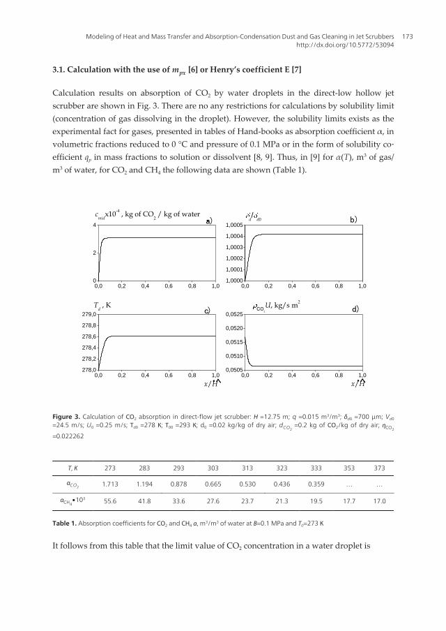
3.1. Calculation with the use of mpx [6] or Henry’s coefficient Е [7]
Calculation results on absorption of СО2 by water droplets in the direct-low hollow jetscrubber are shown in Fig. 3. There are no any restrictions for calculations by solubility limit(concentration of gas dissolving in the droplet). However, the solubility limits exists as theexperimental fact for gases, presented in tables of Hand-books as absorption coefficient α, involumetric fractions reduced to 0 °С and pressure of 0.1 MPa or in the form of solubility co‐efficient qр in mass fractions to solution or dissolvent [8, 9]. Thus, in [9] for α(Т), m3 of gas/m3 of water, for СО2 and СН4 the following data are shown (Table 1).
0,0 0,2 0,4 0,6 0,8 1,00
2
4
0,0 0,2 0,4 0,6 0,8 1,01,0000
1,0001
1,0002
1,0003
1,0004
1,0005
0,0 0,2 0,4 0,6 0,8 1,0278,0
278,2
278,4
278,6
278,8
279,0
0,0 0,2 0,4 0,6 0,8 1,00,0505
0,0510
0,0515
0,0520
0,0525
・cmid
x10-4 , kg of CO
2 / kg of water
a)
b)d/d0
・ヘ
c)
・ヘ
Td , K
x/H x/H
d)CO2
U, kg/s m2
Figure 3. Calculation of СО2 absorption in direct-flow jet scrubber: Н =12.75 m; q =0.015 m3/m3; δd0 =700 μm; Vd0
=24.5 m/s; U0 =0.25 m/s; Тd0 =278 К; Т00 =293 К; d0 =0.02 kg/kg of dry air; dCO2 =0.2 kg of СО2/kg of dry air; ηCO2
=0.022262
Т, К 273 283 293 303 313 323 333 353 373
αCO2 1.713 1.194 0.878 0.665 0.530 0.436 0.359 … …
αCH4∙103 55.6 41.8 33.6 27.6 23.7 21.3 19.5 17.7 17.0
Table 1. Absorption coefficients for СО2 and СН4 α, m3/m3 of water at В=0.1 MPa and Т0=273 К
It follows from this table that the limit value of СО2 concentration in a water droplet is
Modeling of Heat and Mass Transfer and Absorption-Condensation Dust and Gas Cleaning in Jet Scrubbershttp://dx.doi.org/10.5772/53094
173

сmсо2,lim =αсо2ρсо2(Т0, В0)=αсо2(Т)Мсо2
В0
RТ0=αсо2
44⋅1013258, 314⋅103⋅273
=
=1, 964⋅10−3⋅αсо2(Т),кgСО2кgwater ,
(43)
where αсо2(Т) is the table value of absorption coefficient for СО2 (Table 1).
This value shall limit concentration of СО2 dissolved in the droplet. It can be seen in Fig. 3а)that according to Table 1 calculated value of сmid does not reach the solubility limit and it isone order lower. Thus, сmid ,lim (Тd =278, 63К, see Fig. 3c)) =2.81∙10-3 kg of СО2/kg of water. Itcan be seen in Fig. 3b) that as a result of water vapor condensation and СО2 absorption thesize of droplet increases insignificantly, less than by 0.05 %, i.e., a small amount of water va‐pors condenses on the droplet and a small amount of СО2 is absorbed by the droplet, Fig.3а). The calculated amount of the mass of gas component absorbed by liquid droplets in thescrubber is determined by formula, kg/h∙m2,
, . .,0 0 0 3600.i th d a i iW d Ur h= (44)
For calculated situation with consideration of partial density of dry air at the inlet ρd .a.,0
=1.0363 kg/m3, gas content dСО2,0=0.2 kg/kg of dry air, U0=0.25 m/s and ηСО2
=0.022262 accord‐
ing to formula (44) we will obtain
,21,0363 0,2 0,25 0,022262 3600 4,153 .i thW kg h m= × × × × ×= (45)
Let’s compare the obtained result with the value achieved via the empirical volumetric masstransfer coefficient, shown in [6, p. 562] (in our nomenclature):
3
0,67,00,9 0,45 0,65
0NH ,0
1/72 .0 h,iiv
DU Q H
Db -
æ öç ÷=ç ÷è ø
(46)
Here Q is irrigation density, m/h, DNH3,0=0,198 10-4 m2/s is coefficient of methane diffusion in
air at В0=0.1 MPa and Т0=273 К, Н is calculated scrubber height, m.
Let’s write down the value of obtained coefficient per an area unit of apparatus cross-sectionvia coefficient βiv in the following form, kg/h∙m2:
, ,i e iv iW lb r= D (47)
Mass Transfer - Advances in Sustainable Energy and Environment Oriented Numerical Modeling174

where Δρi is calculated concentration pressure on the way of gas component obtaining х=0,х=l, where l corresponds to the coordinate, where thermodynamic equilibrium is achievedfor the i-th component in the flow.
Substituting (46) into (47) and assuming l=H, as it was made at treatment of experimentaldata in [6], we get
( )3
0,670,45 ,00,9 0,35
, 0N
20
H ,0kg h720 3600 m, ,i
i e iD
W U U q HD
ræ öçDç ÷è
×÷=ø
(48)
where q is irrigation coefficient, m3 of water/ м3 of vapor-gas flow at apparatus inlet.
Let’s transform formula (48), and finally for calculation we obtain dependence
3
0,67,01,35 0,45 0,35
, 0NH ,0
28685,9 .ii e i
DW U q H
Dræ öç ÷= Dç ÷è ø
(49)
For the considered situation Di ,0 =DCO2,0=0, 138⋅10−4m2/s [6].
Let’s take the average experimental data of [6] as the calculation working height of absorberНave=(Нmin Hmax)1/2=(4.3 12)1/2≈7 m, then for calculated valueΔρСО2
=ρd .a.,0dСО2,0ηi =1, 0363⋅0, 2⋅0, 022262=0, 004614 kg/m3
( ) ( ) ( )0,67
1,35 20,45 0,35,
0,13828685,9 0,25 0,015 7 0,004614 4,7720,198
kg h mi eW æ ö× »ç ÷
ø×=
è(50)
since Di =Di ,0B0B ( TT0
)1,75 and total multiplier
B0B ( TT0
)1,75 in (50) is reduced.
Calculated (45) and experimental (50) results differ by Δ≈13 %. If we take Н=4.3 m, thenW i ,e =4, 024 kg/h m2 and Δ≈3 %. At Н=12 m, W i ,e =5, 76 kg/h m2 and Δ=28 %.
It follows from formula (42) for calculated concentration difference at apparatus inlet andoutlet that
Δρi ,cal =(UoutU0
−1)ρiin + Δρi,
where calculated value is Δρi ,cal =ηiρi ,in. Thus, for Uout= U0 Δρi ,cal =ηiρi ,in =Δρi, i.e., the calcu‐lated value of concentration difference coincides with real value Δρi. Therefore, we canmake a conclusion that efficiency of dust capture and mass transfer shall be calculated not
Modeling of Heat and Mass Transfer and Absorption-Condensation Dust and Gas Cleaning in Jet Scrubbershttp://dx.doi.org/10.5772/53094
175

by the measured difference of dust concentrations and extracted gas components at the inletand outlet, but by difference of their mass fluxes in accordance with the law of mass conser‐vation, and if velocities at the inlet and outlet are equal or close efficiencies can be calculatedby real concentration difference. Distribution of mass flux of СО2 along the scrubber heightis shown in Fig. 3d). It is obvious from Figs. 3c) and 3d) that the process of absorption com‐pletes long before the flow escape from the scrubber, for the given version of calculation atх/Н≈0.1 (≈1.3 m). Hence, the residual height of the scrubber is excessive, and it can not bedetermined experimentally.
Previous comparison can be made in the relative form, what will prove the validity of calcu‐lation of mass transfer coefficient as a measure determining process intensity, on the basis ofmodel in comparison with its experimental expression [6]:
( )3 3
, . .,0 0 00,67 0,67
, 0,35,0 ,01,35 0,45 0,35 0,450 0
NH ,0 NH ,0
3600 0,1255 ,
28685,9
i th d a i i
i ei i
i
W d UW D D
U q H q HUD D
r h
r
= =æ ö æ öç ÷ ç ÷Dç ÷ ç ÷è ø è ø
(51)
where it is assumed that Δρi =ηiρd .a.,0di0. Thus, for our caseW i ,thW i ,e
=0, 1255
0, 616⋅0, 151⋅Н 0,35⋅0, 785=
1, 72Н 0,35 =0, 87at Н=7 m and
W i ,thW i ,e
=1, 03 at Н=4.3 m.
Here Δρi has the meaning of efficient drop of gas concentration, not real, but correspondingto extraction of the gas component due to absorption on a liquid droplet. Real drop of СО2
concentrations at the inlet and outlet at the example of Fig. 4 is even negative:ΔρСО2
=ρСО2,in−ρСО2,out
=0, 1245−0, 2099= −0, 0854 kg/m3, here Uin=U0=0.25 m/s, Uout=0.1439m/s.
Extractions per a total volume of apparatus can be presented as, kg/h,
2, , ;i th iv th iG D Hb r pD = D (52)
2, , .i e iv e iG D Hb r pD = D (53)
On the other hand
βiv ,th =ΔGi ,th
ΔρiπD2H
=ρd .a.,i0di0U0ηi3600πD 2
ΔρiπD2H
.
Hence, with consideration of formulas (46) and (53) we will obtain the relationship for volu‐metric mass transfer coefficients (theoretical and experimental ones)
Mass Transfer - Advances in Sustainable Energy and Environment Oriented Numerical Modeling176

βiv ,thβiv ,e
=3600U0ΔρiπD
2
28685, 9U01,35q 0,45H −0,65Δρi( Di ,0
DN H 3,0)0,67
πD 2Н,
after elementary reductions in numerator and denominator this corresponds to formula (51).Here D is apparatus diameter.
Calculations results for the same situation as in Fig. 3 are shown in Fig. 4, but for the in‐creased moisture content d0=0.5 kg/kg of dry air. The theoretical value of absorbed СО2 is:
W i ,th =0, 6226⋅0, 2⋅0, 25⋅0, 029136⋅3600=3, 265 kg/h•m2.
0,0 0,2 0,4 0,6 0,8 1,00,0
0,5
1,0
1,5
2,0
2,5
3,0
0,0 0,2 0,4 0,6 0,8 1,01,000
1,002
1,004
1,006
1,008
1,010
0,0 0,2 0,4 0,6 0,8 1,0278
280
282
284
286
0,0 0,2 0,4 0,6 0,8 1,00,0300
0,0305
0,0310
0,0315
・cmid
x10-4 , kg of CO
2 / kg of water
b)
a) d/d0
x/Hx/H
c)
・ヘ
Td , K
・ヘ
d)CO2
U, kg/s m2
Figure 4. Fig. 4. Calculation of СО2 absorption in the direct-flow jet scrubber: Н =12.75 m; q =0.015 m3/m3; δd0 =700μm; Vd0 =24.5 m/s; U0 =0.25 m/s; Тd0 =278 К; Т00 =293 К; d0 =0.5 kg/kg of dry air; dCO2
=0.2 kg of СО2/kg of dry air; ηCO2
=0.029136
Calculation by formula (48) for height Н=4.3 m gives the following
W i ,e =28685, 9⋅ (0, 25)1,35(0, 15)0,45(4, 3)0,350, 00363⋅0, 785=3, 165 кg/h•m2,
what differs from the theoretical value by 3 %. Here ΔρСО2=0, 00363 kg/m3 by calculation
(ΔρСО2=0, 62226⋅0, 2⋅0, 029136). We should note that even for the increased moisture con‐
tents the size of droplets increases slightly due to condensation and absorption (less than by1 %) (Fig. 4b). For calculated scrubber height Нave=7 m W i ,e =3, 75 kg/h∙m2 (Δ=15.6 %).
According to comparison, the model agrees well with the experimental data.
Modeling of Heat and Mass Transfer and Absorption-Condensation Dust and Gas Cleaning in Jet Scrubbershttp://dx.doi.org/10.5772/53094
177

In calculations tabular data mрх for water solution of СО2 [6] were approximated by tempera‐ture dependence Т,
( )2 42,389 994,6 100765 1 Pa.0 ,pxm T T= - + (54)
Partial pressures of saturated water vapors on droplet and “formation” surfaces were calcu‐lated by formula [2] (the partial pressure of saturated vapors of gas components were nottaken into account)
,, cr 1 2 2
crexp ln ,d
sdT
P P A A fT
dd
æ ö= +ç ÷ç ÷
è ø(55)
where
f 2 =4( Тd ,δTcr
−1)TTcr
+ f −1 5, 3lnТd ,δTcr
,
f 1 =( Тd ,δTcr
−1) ( Тd ,dTcr
+ 1)2
5 + 0, 5 ,
Рcr = 221.29 105 Па; tcr = 374.1 °С; А1 = 7.5480; А2 = 2.7870.
For hydrogen sulfide mрх for water solution [6] was approximated by dependence:
( )2 40,0251 148,73 36374 10 , Pa.pxm T T= - + - (56)
Calculation results on absorption of hydrogen sulfide on a water droplet from the vapor-gasflow are shown in Fig. 5.
Theoretical value of W i ,th for Н2S (ρd .a.,0 =1, 0029kg/m3) is
,21,0029 0,2 0,25 0,062478 3600 11,28 kg/h m .i thW = × × × × = (57)
Calculation by formula (48) with experimental mass transfer coefficient gives for Н=4.3 m
Mass Transfer - Advances in Sustainable Energy and Environment Oriented Numerical Modeling178

,228685,9 0,1539 0,151 1,66615 0,01253 0,7426 10,335 kg/h m , i eW = × × × × × = (58)
where ( DH 2S
DNH3
)0,67
=( 0, 1270, 198 )0,67
=0, 7426, ΔρH 2S≈ηρSO2,0
≈0, 22031⋅1, 0029⋅0, 2=0, 01253
kg/m3. Difference between results of (57) and (58) is Δ≈8 %. For calculated height Н=7 mW i ,e =12, 257 kg/h m2 and Δ≈8 % on the other hand. In calculations for Н2S the limit of con‐centration (solubility) in water is not exceeded (solubility for 20 °С is about 3.85 10-3 kg ofН2S/kg of water) (see Fig. 5а)). According to the diagrams, here absorption is completed at1.3 – 1.5 m from the scrubber inlet.
0,0 0,2 0,4 0,6 0,8 1,00,0
0,2
0,4
0,6
0,8
1,0
0,0 0,2 0,4 0,6 0,8 1,01,0000
1,0001
1,0002
1,0003
1,0004
1,0005
1,0006
0,0 0,2 0,4 0,6 0,8 1,0278,0
278,2
278,4
278,6
278,8
279,0
0,0 0,2 0,4 0,6 0,8 1,00,046
0,047
0,048
0,049
0,050
0,051
0,052
・
cmid
x10-3 , kg of H
2S / kg of water
a)
b)d/d0
Td , K
c)
・ヘ x/Hx/H ・ヘ
d)H2SU, kg/s m
2
Figure 5. Calculation of hydrogen sulfide absorption: Н =12.75 m; q =0.015 m3/m3; δd0 =700 μm; Vd0 =24.5 m/s; U0
=0.25 m/s; Тd0 =278 К; Т00 =293 К; d0 =0.02 kg/kg of dry air; dH2S ,0 =0.2 kg of Н2S/kg of dry air; ηH2S=0.062478
3.2. Calculation of absorption by solubility of l and qs
If there are no tabular data for mрх (or Е) of any gas, and solubility information is available inthe hand-book, for instance, for l, m3 of gas/m3 of water and for qs, g of gas/100 g of water,we can relate l and qs to the limit density of saturated gas on the droplet surface ρid,lim., kg/m3,taking into account that the process of its dissolution occurs in droplet volume fast, i.e., thetypical time of gas dissolution is significantly less than the typical time of droplet stay in theworking volume of scrubber. Then,
Modeling of Heat and Mass Transfer and Absorption-Condensation Dust and Gas Cleaning in Jet Scrubbershttp://dx.doi.org/10.5772/53094
179

,lim 10 .sidql
r = (59)
Thus, in [8, p. 260-261] there are tabular data for SO2 for l and qs, where we have shown re‐calculation of ρSO2d ,lim by formula (59) in the last line of Table 2:
t, ºC 0 10 20 30 40
l 79.8 56.7 39.4 27.2 18.8
qs 22.8 16.2 11.3 7.8 5.41
ρSO2d ,lim = 10qsl
2.8571 2.8571 2.8680 2.8676 2.8777
Table 2. Volumetric l and weight qs solubility coefficients for SO
According to this Table, ρSO2d ,lim=2.8655≈2.9 kg/m3 and it is almost constant value.
First, for this case we calculate mрх:
Pid ,lim =PSO2d ,lim =ρSO2d ,limRTdМSO2
=2, 86558, 314⋅103
64 Тd ; (60)
( ) 2
22
SO ,lim
SO SO ,lim;d
pxd
Pm
x= (61)
2
2
2
2
SOSO ,lim 2
SO
10
.10 1
s
ds
water
qM
xqM M
-
-=
+(62)
As a result, the following approximation was obtained by formula (61) for SO2
(mpx)SO2=2976, 58Т 2−1594158Т + 215090898, Pa., (63)
Knowing (mpx)SO2, we determine specific heat of SO2 absorption by water:
Mass Transfer - Advances in Sustainable Energy and Environment Oriented Numerical Modeling180

( )( )2
2 2
SO1SO SO J/kg.
ln,
px
d
mRTM r T
t- =
d
d(64)
Following calculation is performed by the general scheme (formulas (31)–(35)).
Results of calculation are shown in Fig. 6 at ventilation of air humidity d0=0.02 kg/kg of dryair, dSO2,0
=0.2 kg/kg of dry air, dCH4,0=0.2 kg/kg of dry air. Other parameters are shown in
captions to the figure. It was obtained for this calculation version that ηSO2=51.1 %, ηCH4
=0.08%. The limit value of SO2 concentration in a droplet is not achieved even for СН4. Accordingto tabular data on absorption coefficient α, m3/m3 of water (see Table 1):
cmid ,lim =0, 717⋅10−6α, kg of СН4/ kg of water.
According to calculation of extracted SO2 for the given case (ρd .a.,0 =0, 8121kg/m3):
W i ,th =0, 8121⋅0, 2⋅900⋅0, 51072=74, 656 kg/h•m2,
W i ,e =28685, 9⋅0, 1539⋅0, 151⋅ (12)0,35⋅0, 8121⋅0, 2⋅0, 51072⋅0, 715=94, 34 kg/h•m2
for Н=12 m,
W i ,e =28685, 9⋅0, 1539⋅0, 151⋅ (7)0,35⋅0, 8121⋅0, 2⋅0, 51072⋅0, 715=78, 13 kg/h•m2
at Нave=7 m (Нave = 4, 3⋅12≈7m). Here ( DSО2,0
DNH3,0)0,67
=0, 715.
Comparison of W i ,th and W i ,e for SO2 proves good agreement between theory and experi‐ment.
According to calculation, Fig. 6c), methane is not absorbed by water. However, even formethane comparison of calculation with experiment yields satisfactory agreement:
W i ,th =0, 1624⋅900⋅0, 00079541=0, 11626 kg/h•m2;
W i ,e =28685, 9⋅0, 1539⋅0, 151⋅0, 1624⋅0, 00079541⋅0, 715=0, 1026 kg/ h•m2
at Н=4.3 m, Δ=11.75 %. At Н=7 m, W i ,e =0, 1217 kg/ h∙m2 and Δ=4.5 %.
We should note that absorber height Н in experimental dependence for βiv is taken improper‐ly. The optimal and calculated height of setup should equal path l, where the process of com‐ponent extraction is completed. In most cases of calculations, it completed earlier at the heightless than the accepted height of absorber Н=12.75 m. Therefore, at comparison of calculationand experimental data in experimental dependence for mass transfer coefficient we have var‐ied the calculated height in the range of the heights of tested setups from 4.3 to 12 m [6].
For СН4 mрх is approximated by dependence
Modeling of Heat and Mass Transfer and Absorption-Condensation Dust and Gas Cleaning in Jet Scrubbershttp://dx.doi.org/10.5772/53094
181

mpx =(−47, 154Т 2 + 35490Т −5962310) 104, Pa. (65)
0,0 0,2 0,4 0,6 0,8 1,01,0000
1,0005
1,0010
1,0015
1,0020
1,0025
0,0 0,2 0,4 0,6 0,8 1,0278,0
278,2
278,4
278,6
278,8
279,0
0,0 0,2 0,4 0,6 0,8 1,00,04055
0,04060
0,04065
0,0 0,2 0,4 0,6 0,8 1,00
1
2
3
4
5
6
0,0 0,2 0,4 0,6 0,8 1,00,0
0,2
0,4
0,6
0,8
1,0
0,0 0,2 0,4 0,6 0,8 1,00,015
0,020
0,025
0,030
0,035
0,040
0,045
・d/d0
x/Hx/H
a)
b)Td, K
c)CH4
U, kg/s m2
d)
・ヘ
cmid
x10-3
, kg of SO2 / kg of water
・ヘ
e)cmid
x10-5 , kg of CH
4 / kg of water
f)SO2
U, kg/s m2
Figure 6. Calculation of SO2 and CH4 absorption in direct-flow jet scrubber: Н =12.75 m; q =0.015 m3/m3; δd0 =700 μm;Vd0 =24.5 m/s; U0 =0.25 m/s; Тd0 =278 К; Т00 =293 К; d0 =0.02 kg/kg of dry air; dSO2,0 =0.2 kg/kg of dry air; dCH4,0 =0.2
kg/kg of dry air; ηSO2=0.51064; ηCH4
=0.00079541
3.3. Calculation of combined absorption-condensation dust-gas cleaning
Calculations of combined condensation dust capture and absorption extraction of hydrogensulfide from the vapor-air flow in direct-flow hollow scrubber are shown in Fig. 7. Calculat‐ed parameters are shown below the figure. According to Fig. 7а), even at increased moisturecontent the size of droplets increases weak due to condensation. Therefore, for similar proc‐esses the equation of droplet motion can be calculated with a constant mass.
An increase in the size of “formations” is more significant due to condensation of water va‐pors on them: for δ0=0.01 μm it is 2.1, for δ0=0.1 μm it is 2.3, and for δ0=1 μ it is 32 and morefor the same total concentration of dust at the inlet of 1.72 g/m3. In the first case, particles arenot caught, in the second case, about 5.76 % of particles are caught, and in the third case, 100% of particles are caught at the inlet to the apparatus. For this version of calculation the sta‐ble state by concentrations of Н2S dissolved in droplets and in condensate on “formations”
Mass Transfer - Advances in Sustainable Energy and Environment Oriented Numerical Modeling182

occurs far from the flow escape from the scrubber. For particles water vapor condensation atflow escape from the scrubber has been also competed already (see Fig. 7g). Therefore, inthis case the height of absorber above 1.5 m is excessive, and in construction it can be limitedby 2 m. According to Figs. 7d) and 7e), concentration of Н2S dissolved in condensate on theparticle and in droplets increases, but it does not exceed the solubility limit (in this case it isabout 3.85∙10-3 kg of Н2S/kg of water).
0,0 0,2 0,4 0,6 0,8 1,01,000
1,001
1,002
1,003
1,004
0,0 0,2 0,4 0,6 0,8 1,0278
279
280
281
282
283
0,0 0,2 0,4 0,6 0,8 1,00,032
0,033
0,034
0,035
0,036
0,037
0,0 0,2 0,4 0,6 0,8 1,00
2
4
6
8
0,0 0,2 0,4 0,6 0,8 1,00
2
4
6
8
0,0 0,2 0,4 0,6 0,8 1,0-2
0
2
4
6
0,0 0,2 0,4 0,6 0,8 1,00
10
20
30
40
・
d/d0
x/H
x/H
a)
b)Td , K
c)H2SU, kg/s m
2
d)cmid
x10-4
, kg of H2S / kg of water
e)cmi
x10-4
, kg of H2S / kg of water
・ヘ
f)pU x10
-4, kg/s m
2
j)/0
・ヘ
Figure 7. Calculation of combined air cleaning from submicron dust and hydrogen sulfide in direct-flow scrubber: Н=2 m; q =0.015 m3/m3; δd0 =700 μm; Vd0 =24.5 m/s; U0 =0.25 m/s; Тd0 =278 К; Т00 =333 К; d0 =0.2 kg/kg of dry air; dH2S ,0
=0.2 kg/kg of dry air; ρp0 =1.72 g/m3; δ0=1 μm; ηH2S=0.075411; ηp=1.0
3.4. Calculation of absorption and condensation dust capture in Venturi scrubber
Calculation results on Н2S absorption and condensation capture of dust with different sizesin Venturi scrubber are shown in Fig. 8. As an example the Venturi scrubber with followingparameters was chosen for calculations: diameter of Venturi tube mouth dm=0.02 m, diffuser
Modeling of Heat and Mass Transfer and Absorption-Condensation Dust and Gas Cleaning in Jet Scrubbershttp://dx.doi.org/10.5772/53094
183

length l=0.2 m, diffuser opening angle α=6° (α=6–7°, l/dm=10–15 are recommended for nor‐malized Venturi tube [6, 10]), vapor-gas flow velocity in the tube mouth U0=80 m/s, initialvelocity of droplets in the tube mouth Vd0=4 m/s, irrigation coefficient q=0.015 m3/m3, tem‐perature of the vapor-gas flow and droplets in the tube mouth Т00=333 К and Тd0=278 К, re‐spectively, concentration of dust particles at the inlet ρp0=1.72 g/m3, size of dust particlesδ0=0.1 μm, moisture content in water vapor at the inlet was set d0=0.2 kg/kg of dry air, gascontent dH 2S ,0 =0.1 kg/kg of dry air. Efficient of Н2S extraction and dust capture were deter‐mined ηH 2S
=0.072959 and ηp=0.52904, respectively.
The mean-mass size of droplets in the tube mouth was calculated by Nukiyama-Tanasavaformula [1]:
0,45
1,50
0 0
0,585 53,4 , m,f fd
d f f f
qU V
s md
r r s
æ öç ÷= +ç ÷-è ø
(66)
where ρf (kg/m3), μf (Pa∙s), σf (N/m) and q (m3/m3) are density, dynamic viscosity, surfacetension coefficient of pneumatically atomized liquid, and irrigation coefficient.
Velocity U was calculated with consideration of diffuser expansion angle [2, 11].
Dependences of droplet size along the diffuser length are presented in Fig. 8а). It can beseen that firstly condensation of water vapors occurs intensively, then this process stops atthe length of х/l≈0.2, and the size of droplets stays constant up to the scrubber outlet. At this,the quantitative droplet size changes slightly along the diffuser length (it stays almost con‐stant: the maximal increase is a little bit higher than 0.3 %).
A change in droplet temperature due to convective heat transfer between droplets and va‐por-gas flow, thermal effects of water vapor condensation on droplets, and gas dissolution isshown in Fig. 8d). A change in mass concentration of Н2S dissolved in a droplet is shown inFig. 8c). It is obvious that absorption is almost completed at the length of tube diffuser 1 forthis version of calculation. The same circumstance is illustrated by mass concentration ofН2S in “formation” condensate along the diffuser in Fig. 8c). According to the figure, the sol‐ubility limit on “formations” and droplets is not achieved as in the hollow jet scrubbers. Achange in “formation” size due to water vapor condensate on their surfaces is illustrated inFig. 8f). It can be seen that firstly water vapors condense very intensively, then at the dis‐tance of about x/l≈0.1 this process completes, the size increases more than twice and staysconstant until the leaving from the scrubber. Efficiency of dust capture in this version is upto 53 %. Calculation at the same parameters of the vapor-gas flow and dust at the scrubberinlet with mouth dг=0.1 m and constrictor length l=1 m gives ηp=0.77729, ηH 2S
=0.074965. It fol‐lows from the diagrams in this figure that for the calculated version it is practically reasona‐ble to be limited by diffuser length x/l≈0.4 (х=0.08 m), where the processes of dust capture(Fig. 8g)) and absorption are completed (Fig. 8b)). Therefore, the residual length of 0.12 m is
Mass Transfer - Advances in Sustainable Energy and Environment Oriented Numerical Modeling184

excessive. Figs. 8b) and 8g) illustrate distributions of dust and Н2S mass fluxes along the dif‐fuser of Venturi tube.
0,0 0,2 0,4 0,6 0,8 1,01,000
1,001
1,002
1,003
1,004
1,005
0,0 0,2 0,4 0,6 0,8 1,01,75
1,80
1,85
1,90
0,0 0,2 0,4 0,6 0,8 1,00
2
4
0,0 0,2 0,4 0,6 0,8 1,0278
279
280
281
282
283
0,0 0,2 0,4 0,6 0,8 1,00
2
4
0,0 0,2 0,4 0,6 0,8 1,01,0
1,5
2,0
2,5
0,0 0,2 0,4 0,6 0,8 1,02,0
2,5
3,0
3,5
4,0
4,5
・d/
d0 a)
b)H2SU S x10
-3, kg/s
c)cmid
x10-4
, kg of H2S / kg of water
d)Td , K
e)cmi
x10-4
, kg of H2S / kg of water
f)/0
x/H
x/H
j)pUS x10
-5, kg/s
Figure 8. Calculation of Н2S absorption and dust capture in Venturi scrubber (calculated parameters are presented inthe text)
It is necessary to note that these calculation versions do not meet the conditions of optimalscrubber operation; they only illustrate the character of complex gas cleaning. To determinethe optimal regimes, a series of calculation on the basis of suggested model should be car‐ried out and analyzed for the specific industrial conditions.
Let’s turn to comparison of calculation results with the known experimental data. The ex‐perimental volumetric mass transfer coefficient is shown in [6] for NH3 absorption in theVenturi tube with mouth diameter dm=0.02 m. There no geometrical and other parameters.This coefficient is presented as
3NH 1,56 0,57, 0260 ,iv e lU qb = (67)
Modeling of Heat and Mass Transfer and Absorption-Condensation Dust and Gas Cleaning in Jet Scrubbershttp://dx.doi.org/10.5772/53094
185

where ql is irrigation coefficient in l/m3, U0 is in m/s, and βiv is in 1/h.
The experimental value of Н2S absorbed in Venturi tube is expressed by formula, kg/h,
2H S, , , ,i e iv e i e difG Vb rD = D (68)
where Vdif is diffuser volume, Δρi is calculated drop of gas concentration along the diffuserlength, kg/m3, corresponding to experimental data.
The theoretical value of mass of absorbed gas, kg/h, is
2
2H S
, , , , 0 3600.4m
i th iv th i th dif i thd
G V Up
b r rD = D » D (69)
Then
3
3
2
0 ,,0,67
,NH ,0
, ,NH ,0
36004 ,m
i thi th
i ei
iv e dif i e
dUG
G DV
D
pr
b r
DD=
D æ öç ÷ Dç ÷è ø
(70)
where (see Fig. 9) the volume of truncated cone is
33 2 tg 1 1 .24 2tg
2
mdif
m
d lVd
p aa
é ùæ öê ú= + -ç ÷ç ÷ê úè øë û(71)
Substituting (67), (71) into (70), at α=6°, l=0.2 m, dm=0.02 m, U0=80 m/s, ql=15 l/m3 we get thefollowing, assuming that Δρi ,th ≈Δρi ,e,
,
,0,9457,i th
i e
GG
D=
D(72)
where for Н2S ( Di ,0DNH3,0
)0,67=0.7426, i.e., the difference between the theory and experiment is
less than 6 %, what is a good agreement, considering the assumed parameters for normal‐ized Venturi tube.
Mass Transfer - Advances in Sustainable Energy and Environment Oriented Numerical Modeling186

2
l
md
хD lD
Figure 9. The scheme of Venturi tube
The amount of absorbed Н2S for the version of calculation in Fig. 8 (ηH 2S=0.072959, ρd .a.,0
=0.7541 kg/m3) is
W i ,th =0, 7541⋅0, 1⋅0, 072959⋅803, 14(0, 02)2
4 3600=0, 5 kg/h.
For the scrubber with dm=0.1 m, l=1 m at the same dust and gas parameters at the inletW i ,e =12, 78 kg/h.
The experimental values of efficiency of condensation capture of submicron dust are com‐pared with results of model calculation inn [2, 11, 12] at the example of deposition of ashparticles from cracking gases under the industrial conditions in hollow jet scrubbers [13];good agreement is achieved.
4. The choice of the value of calculated concentration difference for theabsorbed gas component
Let’s consider this important question in detail as an addition to iss. 2 at the example of wa‐ter absorption of SO2, comparing calculation and experimental data [6] on volumetric masstransfer coefficient.
It follows from equation (3) that
( )2 2, 0
0
, ,H
i th id d id i d kg s mW n xb pd r r= - ×- ò d (73)
where, according to formulas (26) and (38)
Modeling of Heat and Mass Transfer and Absorption-Condensation Dust and Gas Cleaning in Jet Scrubbershttp://dx.doi.org/10.5772/53094
187

030
16 .ddx d
Un q
V pd= (74)
In (73) and (74), according to calculation results, it is assumed that δd =δd0.
Let’s put βid from (19) to (73) at Kci =1 and nd from (74), we obtain, proved by estimates,
0, 276Red0,55Sci
0,33>>1, Vdх>>U ,
( )0, 0,45 0,67
0 0
3,312 ,Re Sc
Hid i
i thd d i
xqUW
r rd
-» - ò
d(75)
where
Red ≈Vdхδd0ρμ . (76)
Lets’ turn dependence (74) to the following form using the theorem about an average for in‐tegral:
( ) ( )3
3
0,67 0,67NH 0,22 ,0
, 0 1,45 0,45NH ,0
2
00
3,312 , ,H
ii th id
d dõ
D DW qU x
Vkg s m
Dn r
d- æ öæ ö
ç ÷ç ÷» Dç ÷ç ÷è øè
×ø
ò d (77)
where ν̄ =(μ̄ / ρ̄) is the average value of kinematic viscosity of the vapor-gas flow in thescrubber volume, m2/s, D̄NH3
is the average value of diffusion coefficient of methane NH3,
V̄ dх is average velocity of droplets on the 0–Н way at motion from scrubber inlet to the out‐let, m/s, Δρid = |ρid −ρi | .
Expressing velocity U0 and Vdх in m/h, and assuming δd0 =7⋅10−4m (700 μm),
D̄NH3(Тd ,ave ≈278, 5К)=0, 198⋅10−4( 285
273 )1,75=0, 205⋅10−4m2/s (see Fig. 10 b)),
ν̄ =(285К)≈1, 5⋅10−6 m2/s, V̄ dх ≈5, 25 m/s (see Fig. 10 e)), (DSO2,0 /DNH3,0)0,67 =0, 715, we ob‐
tain for calculation parameters of Fig. 10 W i ,th ≈83 kg/h∙m2, where ∫0
H
Δρiddx =0, 6437 kg/m2
is obtained via model calculation (see Fig. 11).
Mass Transfer - Advances in Sustainable Energy and Environment Oriented Numerical Modeling188

0,0 0,2 0,4 0,6 0,8 1,01,0000
1,0005
1,0010
1,0015
1,0020
1,0025
1,0030
0,0 0,2 0,4 0,6 0,8 1,0278,0
278,2
278,4
278,6
278,8
279,0
279,2
0,0 0,2 0,4 0,6 0,8 1,01
2
3
4
5
6
0,0 0,2 0,4 0,6 0,8 1,00
2
4
6
8
0,0 0,2 0,4 0,6 0,8 1,00
5
10
15
20
25
0,0 0,2 0,4 0,6 0,8 1,00,025
0,030
0,035
0,040
0,045
0,050
0,055
・ヘ
・d /
d0 b)a) Td , K
c)d U x10
-3, kg/s m
2
d)c
SO2dx10
-3 , kg of SO
2 / kg of water
・ヘ
e)V
dx , m/s
x/H x/H
f)SO2
U, kg/s m2
Figure 10. Calculation of SO2 absorption in direct-flow jet scrubber: Н =12.75 m; q =0.015 m3/m3; δd0 =700 μm; Vd0
=24.5 m/s; U0 =0.25 m/s; Тd0 =278 К; Т00 =293 К; d0 =0.02 kg/kg of dry air; dSO2,0 =0.2 kg/kg of dry air; ηSO2=0.51722
We should note that multiplier (Di ,0 /DNH3,0)0,67 was included into formula (76) as a correc‐tion like to was dome for empirical dependence (46).
Numerical calculation by the model give the value of SO2 extraction
2 2, . .,0 SO2
,0 0 SO 3600 1,0743 0,2 0,25 0,51722 kg/h m3600 100 .i th d aW d Ur h= = × × × × × ×= (78)
The difference is 17 %, what is a sequence of simplifications and averaging in dependence(76).
If we assume average concentration difference in accordance to average experimental heightН=7 m Δρi =0, 6437 / 7=0, 092kg/m3, then
W i ,e =28685, 9U01,35q 0,45H 0,35Δρi( Di ,0
DNH3,0)0,67
=28685, 9⋅0, 1539⋅0, 151⋅1, 976⋅0, 092⋅0, 715=86, 6 kg / h ⋅m 2.
The difference with W i ,e=83 kg/h∙m2 is 4.2 %.
Modeling of Heat and Mass Transfer and Absorption-Condensation Dust and Gas Cleaning in Jet Scrubbershttp://dx.doi.org/10.5772/53094
189

If we take Δρi =ρd .a.,0dSO2,0ηSO2
=0, 111 kg/m3, then W i ,e=104.5 kg/h∙m2, what differs from re‐sult of (77) by similar 4.3 % with accuracy of estimation error. This proves the fact that calcu‐lated volumetric mass transfer coefficient agrees empirical dependence (46) of [6].
On the basis of analysis performed the calculated concentration difference should be recom‐mended for practical application as the most appropriate
,0 ,0
Hi i i H
UU
r r rD = - (79)
at determination of the value of extracted gas component by formula (49), thus, it is necessa‐ry to measure ρi ,0, ρi ,H and U0, UH at apparatus inlet and outlet. Calculation of moisturecontent is shown in Fig. 10 c), at this, it was obtained that UH =0, 2234 m/s, ρd .a.,0 =1, 0743kg/m3.
5. Conclusions
The suggested physical-mathematical model of complex heat and mass transfer and conden‐sation-absorption gas cleaning from dust and harmful gaseous components is confirmed bythe known experimental data and can be used for engineering calculations and optimizationof construction and operation parameters of hollow jet scrubbers of direct and counter flowtypes. This was proved by its numerical implementation for the specific conditions. Calcula‐
0 2 4 6 8 10 120,00
0,05
0,10
0,15
0,20
0,25
,d x ,
2
102
SO
0
0 6437 kg /m d
H, m
SO2d , kg / m
3
Figure 11. Distribution of ΔρSO2,d along the scrubber height for calculation parameters of Fig. 10.
Mass Transfer - Advances in Sustainable Energy and Environment Oriented Numerical Modeling190

tions on absorption of some gases (СО2, Н2S, SO2, CH4) on water droplets, dispersed bycoarse centrifugal nozzles in hollow direct-flow jet scrubber and pneumatic Venturi scrub‐ber from wet air is shown in the current paper together with calculation of combined ab‐sorption-condensation air cleaning from Н2S and various-sized fine dust in theseapparatuses at an increased moisture content. The system of model equations is written atsome certain conditions for the multicomponent vapor-gas mixture with particle. Thismakes it possible to use this system for calculation of complex gas cleaning from severalharmful gas components and several fractions of dust particles and investigate regularitiesof this process.
Nomenclature
V→d vector of droplet velocity
U→
nvector of vapor-gas low velocity
g→
vector of gravity acceleration
md droplet mass (variable value due to evaporation-condensation and absorption), kg
cf specific heat capacity of liquid, J/ kg∙К
Тd mean mass temperature of droplets, К
αd heat transfer coefficient of droplet, W/m2∙К
δd mass-median size of droplet, m
Т temperature of vapor-gas flow, К
ri specific heat of absorption, evaporation-condensation, J/kg
cδ specific heat capacity of “formation”, J/kg∙К
ρδ mass concentration of “formations’ in the vapor-gas flow, kg/m3
V c = |V→ d −U→ | module of relative droplet velocity, m/s
ηStk coefficient of “formation” capture by droplets
Tδ mean mass temperature of “formations”, К
βid coefficient of droplet mass transfer with the i-th component of vapor-gas flow by concen‐tration difference, m/s
ρid and ρi partial densities (mass concentrations) of saturated vapors of dissolvent and gascomponents near droplet surface and far from it (in the flow), kg/m3
Modeling of Heat and Mass Transfer and Absorption-Condensation Dust and Gas Cleaning in Jet Scrubbershttp://dx.doi.org/10.5772/53094
191

nd and nδ calculated concentrations of droplets and “formations” in the flow, 1/m3
ρg partial density of non-reacting gas component, kg/m3
ρd mass concentration of droplets, kg/m3
αδ heat transfer coefficient of “formation”, W/m2∙К
δ size of “formation”, m
ρ density of vapor-gas flow, kg/m3
c specific heat capacity of vapor-gas flow, J/ kg∙К
ρp mass concentration of dry dust particles in the flow, kg/m3
ρf density of liquid (droplets), kg/m3
μ dynamic viscosity of vapor-gas flow, Pa∙s
M i molar masses of components of the vapor-gas mixture, kg/kmole
R =8, 314 kJ/kmole∙К universal gas constant
Di diffusion coefficient of mixture component, m2/s
Pi partial pressure of the i-th component of the vapor-gas mixture, Pa
Pid ,δ partial saturation pressures of mixture components, calculated by droplet and “forma‐tion” temperature, Pa
mpx ,i constants of phase equilibrium of solutions of i-ths components of extracted gases, Pa
xid ,δ mole fractions of gas components dissolved in a droplet and “formation” condensate
cmid ,δ mass fractions of gas components in droplet and “formation” dissolvent, kg/kg of dis‐solvent
Мdis molar mass of dissolvent, kg/kmole
dmvδ /dτ rate of “formation” mass change due to evaporation-condensation of liquid, kg/s
δ0 initial size of dust particles, m
ρs density of solution on “formation” due to condensation of liquid vapors and absorp-tionof gas components, kg/m3
d moisture content, kg of vapors/kg of dry non-reacting component of vapor-gas mixture
di gas content, kg of reacting gas component/ kg of dry non-reacting component of vapor-gas mixture
q =Qf /Qsg0 irrigation coefficient
Mass Transfer - Advances in Sustainable Energy and Environment Oriented Numerical Modeling192

Qf volumetric flow rate of liquid, m3/s
Qsg0 volumetric flow rate of vapor-gas mixture at apparatus inlet, m3/s
Author details
M. I. Shilyaev and E. M. Khromova
*Address all correspondence to: [email protected]
Department of heating and ventilation, Tomsk State University of Architecture and Build‐ing, Tomsk, Russia
References
[1] Shilyaev M.I., Shilyaev A.M., Grischenko E.P. Calculation Methods for Dust Catch‐ers. Tomsk: Tomsk State University of Architecture and Building; 2006.
[2] Shilyaev M.I., Khromova E.M., Bogomolov A.R. Intensification of heat and masstransfer in dispersed media at condensation and evaporation. Tomsk: Tomsk StateUniversity of Architecture and Building; 2010.
[3] Shilyaev M.I., Khromova E.M. Simulation of heat and mass transfer in spray cham‐bers. Theoretical Foundations of Chemical Engineering 2008; 42(4) 404-414.
[4] Tumasheva А.V. Modeling of heat and mass transfer processes in jet irrigation cham‐bers: abstract of the thesis of candidate dissertation: 01.04.14: defended on 17.06.2011.Novosibirsk; 2011.
[5] Shilyaev M.I., Shilyaev A.M. Aerodynamics and heat and mass transfer of gas-dis‐persed flows. Tomsk: Tomsk State University of Architecture and Building; 2003.
[6] Ramm V.М. Absorption of Gases. Moscow: Khimiya; 1976.
[7] Pavlov К.F., Romankov P.G., Noskov А.А. Sums and Problems in the Course ofProcesses and Apparatuses of Chemical Technology. The 8th edition, revised andadded. Leningrad: Khimiya; 1976.
[8] Perelman V.I. Brief Hand-Book of a Chemist. Edit. by Corr. Member of AS of USSRB.V. Nekrasov. The 3rd edition, revised and added. Moscow: State Scientific-TechnicalPublishing House of Chemical Literature; 1954.
[9] Goronovsly I.Т., Nazarenko Yu.P., Nekryach E.F. Brief Chemistry Guide. Edit. byAcademician of AS of USSR А.Т. Pilipenko. Kiev: Naukova Dumka; 1987.
Modeling of Heat and Mass Transfer and Absorption-Condensation Dust and Gas Cleaning in Jet Scrubbershttp://dx.doi.org/10.5772/53094
193

[10] Hand-Book on Dust and Ash Capture. Edit by A.A. Rusanov. Moscow: Energia;1975.
[11] Shilyaev M.I., Khromova E.M. Capture of Fine Dust in Jet Scrubbers. In: MohamedEl-Amin (ed.) Mass Transfer in Multiphase Systems and its Applications. Vienna: InTech4; 2011. 311-335.
[12] Shilyaev M.I., Khromova E.M., Grigoriev A.V., Tumashova A.V. Physical-mathemati‐cal model of condensation process of the sub-micron dust capture in sprayer scrub‐ber. Thermophysics and Aeromechanics 2011; 18(3) 409-422.
[13] Uzhov V.N., Valdberg A.Yu. Gas Cleaning by Wet Filters. Moscow: Khimiya; 1972.
Mass Transfer - Advances in Sustainable Energy and Environment Oriented Numerical Modeling194