modeling of cyclic load-deformation behavior of …modeling of cyclic load-deformation behavior of...
TRANSCRIPT
Modeling of Cyclic Load-Deformation Behavior of Shallow Foundations Supporting Rocking Shear Walls
Sivapalan GajanUniversity of California, Davis
Presentation
University of Missouri, Rolla
03. 22. 2005

Overview
IntroductionGeotechnical Earthquake EngineeringSoil-Foundation-Structure Interaction
Physical ModelingCentrifuge Experiments
Constitutive ModelingFooting-Soil Interface Behavior
Numerical ModelingImplementing the Model in Finite Element Analysis

Collapse of Engineered Structures
Niigata Earthquake, 1964
Kobe Earthquake, 1995
San Fernando Earthquake, 1971
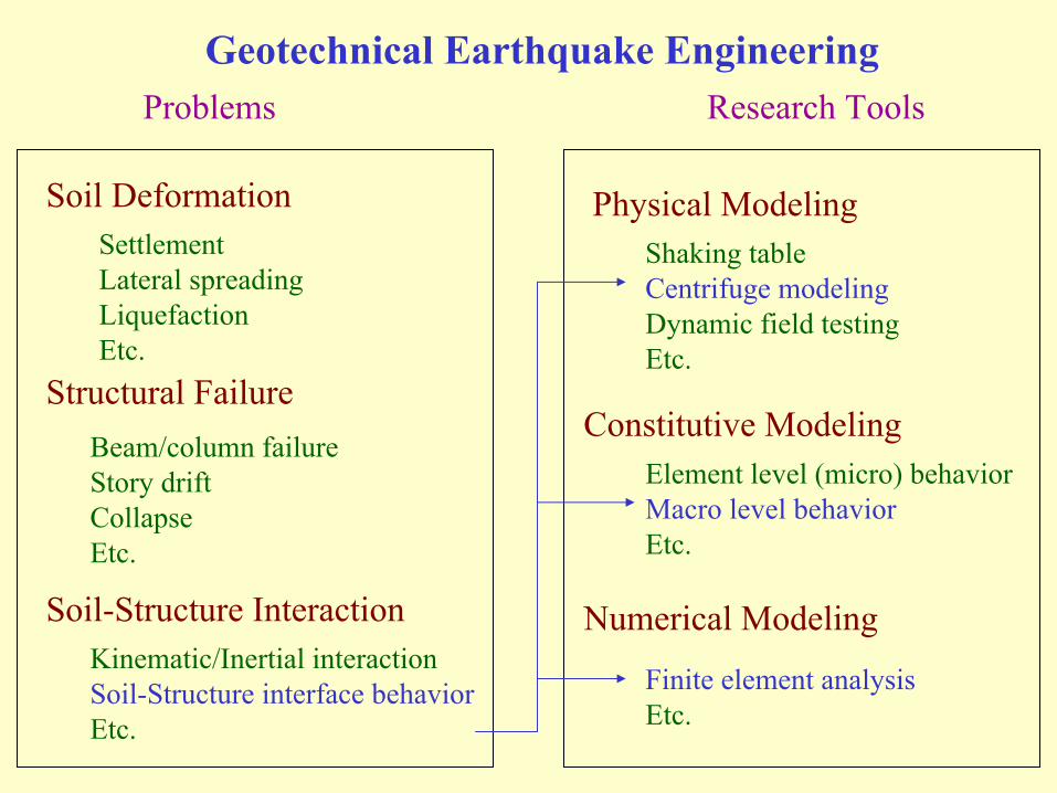
Geotechnical Earthquake Engineering
Soil Deformation
Structural Failure
Soil-Structure Interaction
SettlementLateral spreadingLiquefactionEtc.
Beam/column failureStory driftCollapseEtc.
Kinematic/Inertial interactionSoil-Structure interface behaviorEtc.
Physical Modeling
Constitutive Modeling
Numerical Modeling
Shaking tableCentrifuge modelingDynamic field testingEtc.
Element level (micro) behaviorMacro level behaviorEtc.
Finite element analysisEtc.
Problems Research Tools
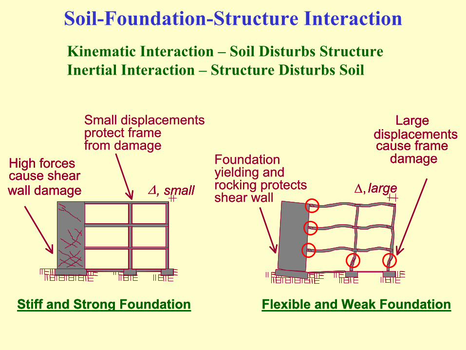
Soil-Foundation-Structure Interaction
∆, small
Stiff and Strong Foundation
High forcescause shearwall damage ∆, large
Flexible and Weak Foundation
Foundationyielding androcking protectsshear wall
Largedisplacementscause frame
damage
Small displacementsprotect framefrom damage
∆, small∆, small
Stiff and Strong Foundation
High forcescause shearwall damage
High forcescause shearwall damage ∆, large∆, large
Flexible and Weak Foundation
Foundationyielding androcking protectsshear wall
Largedisplacementscause frame
damage
Largedisplacementscause frame
damage
Small displacementsprotect framefrom damage
Kinematic Interaction – Soil Disturbs StructureInertial Interaction – Structure Disturbs Soil

Shallow foundations supporting rocking shear wallsPartial separation of footing (uplift) and soil yielding – depend on each other
Location of footing-soil contact area and highly nonlinear bearing pressure distribution changes rapidly
Base shear loading produces sliding of footing
Shear wall and frame structure
(after ATC, 1997)
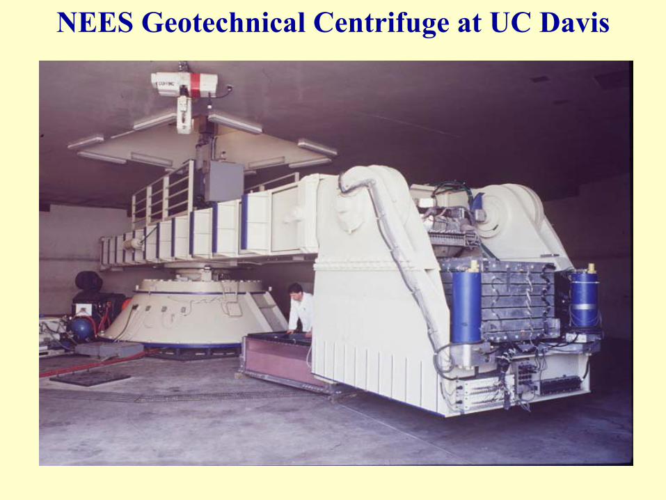
NEES Geotechnical Centrifuge at UC Davis
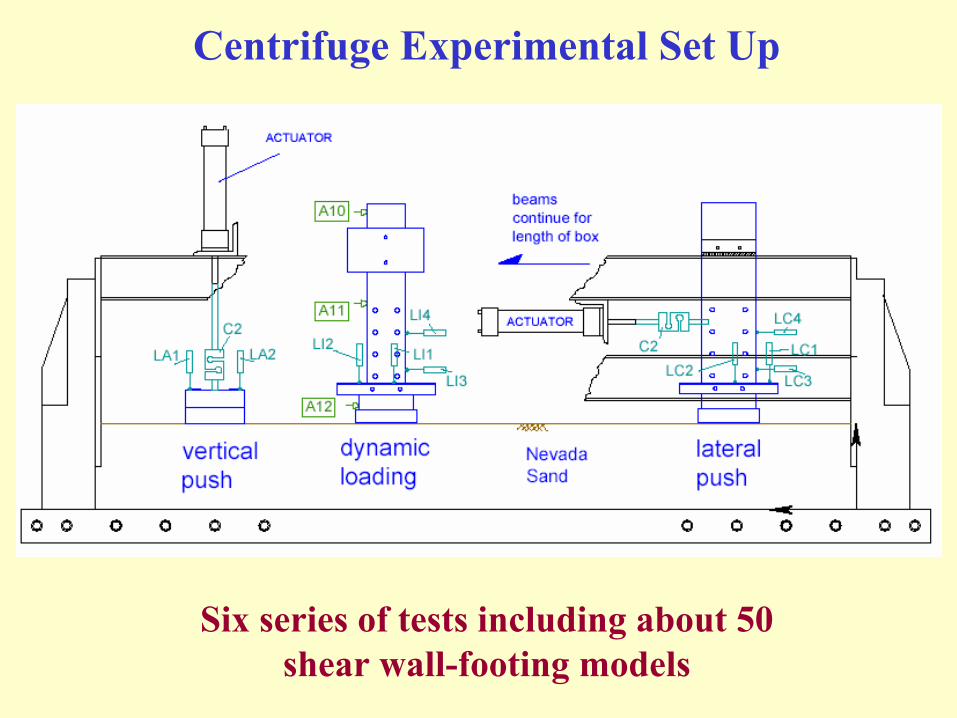
Centrifuge Experimental Set Up
Six series of tests including about 50 shear wall-footing models

Parameters VariedSoil properties
Soil type (dry sand and saturated clay)Dr = 80% and 60% and Cu = 100 kPa
Structure propertiesShear wall weight (FSV = 2 to 10)Height of center of gravity and moment of inertiaFooting geometry (rectangular and square)Footing embedment (D = 0 to 3B)
Loading typesPure vertical loadingLateral cyclic loading
Controlling moment to shear ratio (one actuator)Controlling rotation and sliding (two actuators)
Dynamic base shaking
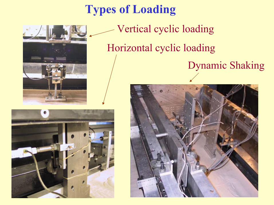
Vertical cyclic loading
Horizontal cyclic loading
Dynamic Shaking
Types of Loading
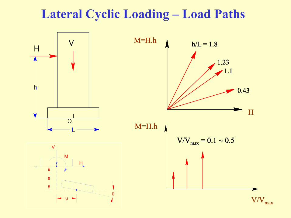
Lateral Cyclic Loading – Load Paths
1.23 1.1
0.43
M=H.h
H
h/L = 1.8
M=H.h
V/Vmax
V/Vmax = 0.1 ~ 0.5
1.23 1.1
0.43
M=H.h
H
h/L = 1.8
1.23 1.1
0.43
M=H.h
H
h/L = 1.8
M=H.h
V/Vmax
V/Vmax = 0.1 ~ 0.5
M=H.h
V/Vmax
V/Vmax = 0.1 ~ 0.5
s
uθ
M
V
H

FS = 6.0, D = 0.0 m, L = 2.8 m, h = 4.9 m
Experimental Results: (V, H, M – s, u, θ) - Sand

FS = 3.0, D = 0.0 m, L = 2.7 m, h = 4.6 m
Experimental Results: (V, H, M – s, u, θ) - Clay
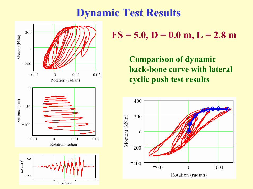
FS = 5.0, D = 0.0 m, L = 2.8 m
Dynamic Test Results
Comparison of dynamic back-bone curve with lateral cyclic push test results
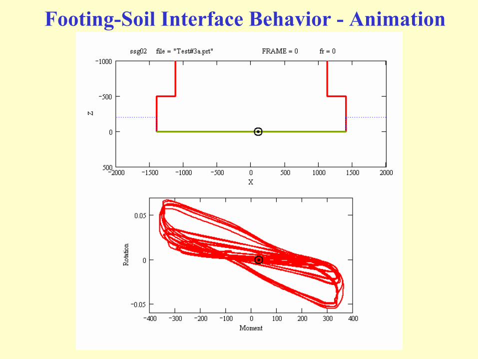
Footing-Soil Interface Behavior - Animation

Eccentricity Animation – Experiment
Contact lengthFSCurvature (θmax)
Pressure distributionSoil typeContact length
θ
θ+
θθ
⋅=θθ
θθ
⋅=θθ
θ⋅=θ
d)(de
d)(deR
d)(dM
d)(deR
d)(dM
)(eR)(M
pressurecontact
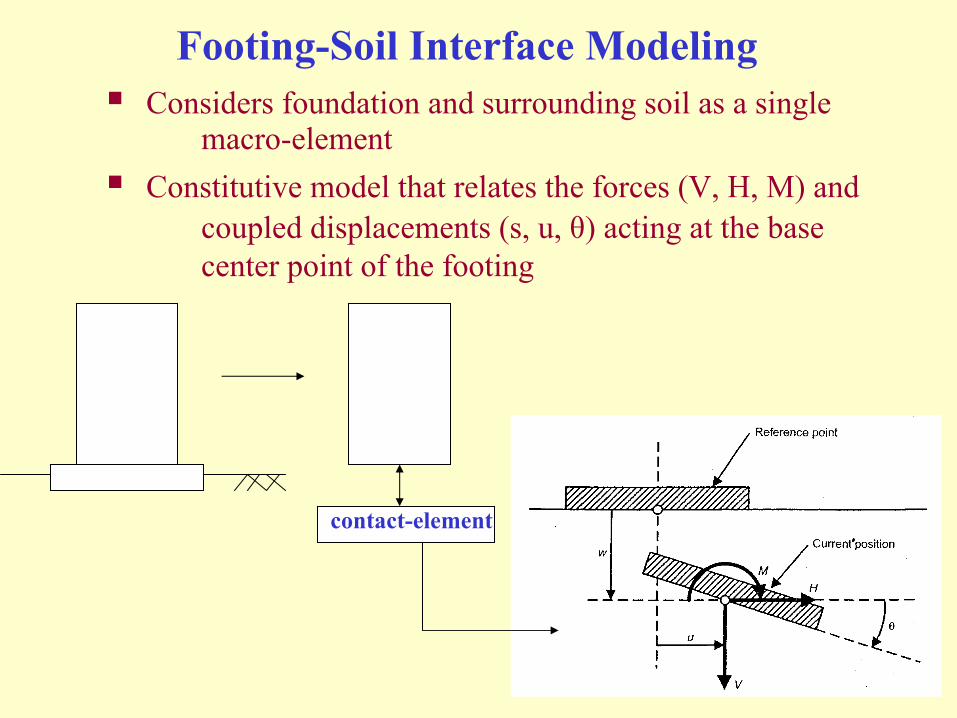
Footing-Soil Interface Modeling
contact-element
Considers foundation and surrounding soil as a single macro-element
Constitutive model that relates the forces (V, H, M) and coupled displacements (s, u, θ) acting at the base center point of the footing

Modeling of Moment-Rotation Behavior
Footing locationCurrent soil surface location (soil_min)Maximum past settlement (soil_max)Current bearing pressureMaximum past pressure experienced
Internal variables
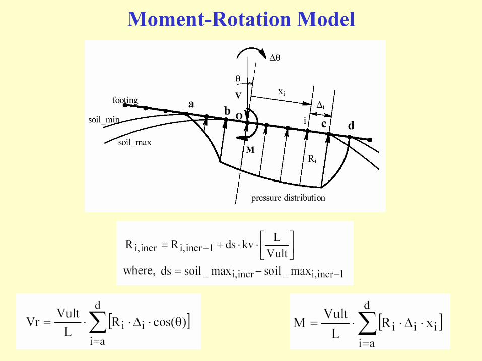
Moment-Rotation Model

Model Simulations (FS = 6) - Animation
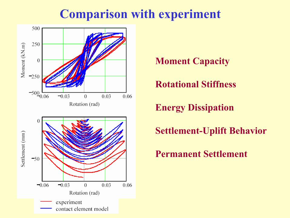
Comparison with experiment
Moment Capacity
Rotational Stiffness
Energy Dissipation
Settlement-Uplift Behavior
Permanent Settlement

Shear–Sliding Modeling: Coupling with V
1
0
p[i]
i_nodeFS1
qult]i[q]i[p
==
10 p[i]Vult
VFS1Fv ==
VultHFh = [ ]Fv1Fv
21Fh −⋅⋅=

Shear-Sliding Modeling: Coupling with M
1BFh
AFm
2
2
2
2=+
LVultMFm⋅
=
VultHFh =
du
dθ
−
=din_d
dglobal_f
When (d d_in)f_global infinite
When (d 0)f_global 0
2
2
2
2
AB
Lh
AB
FhFm
dud
⋅=⋅=θ
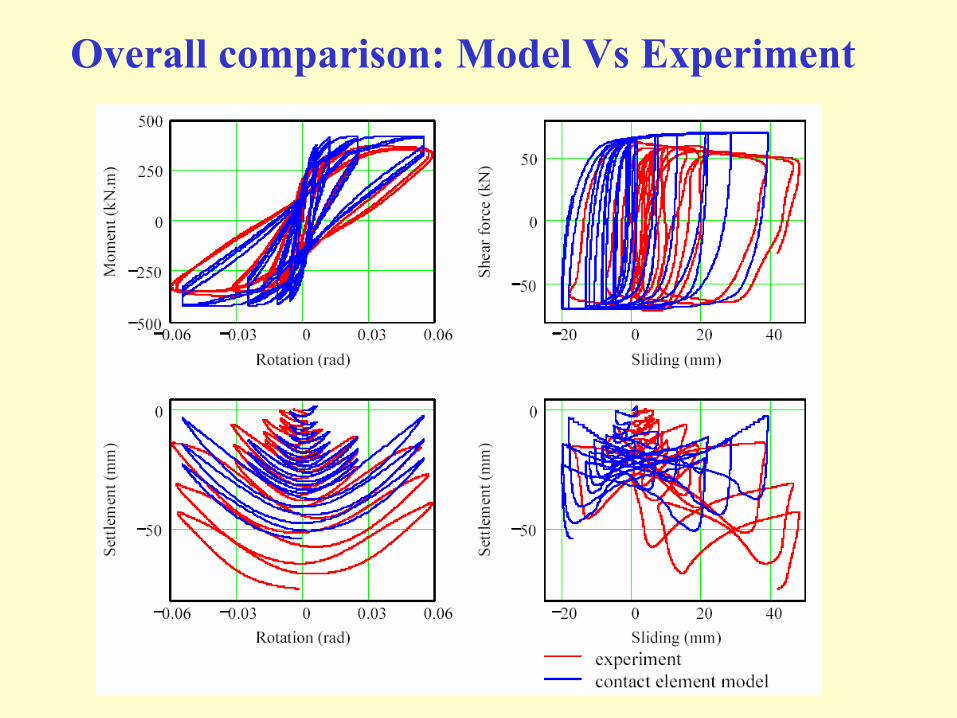
Overall comparison: Model Vs Experiment
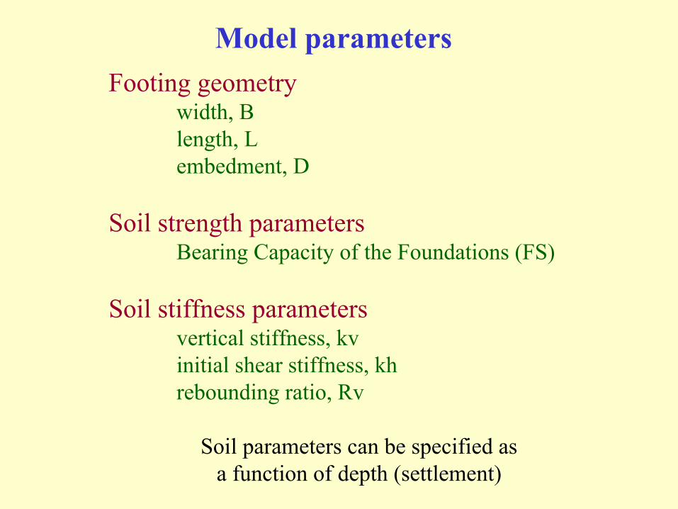
Model parametersFooting geometry
width, Blength, Lembedment, D
Soil strength parametersBearing Capacity of the Foundations (FS)
Soil stiffness parameters vertical stiffness, kvinitial shear stiffness, khrebounding ratio, Rv
Soil parameters can be specified as a function of depth (settlement)
Implementation in OpenSEESWhat is OpenSEES ?
Open System for Earthquake Engineering SimulationsA finite element framework (open source) that is being
developed by PEER
What is PEER ?Pacific Earthquake Engineering Research CenterOne of the NSF funded Earthquake Engineering Research
centers in USADevelops tools for Performance Based Earthquake
Engineering (PBEE) design
What is PBEE ?Design, evaluation and construction of engineered
structures whose seismic performance meets the diverse economic and safety needs of owners and society

OpenSEES FE Framework
NodeElementMaterialLoad patternConstraintsEtc….
Nodal displacementsElement forcesEtc….
System of equationsSolution algorithmIntegratorEtc….
Model Builder
Recorder
AnalysisDomain
Builds the model
Records everything thathappens in Domain
Performs analysisin Domain
Model Builder stores everythingAnalysis performs analysisRecorder gets the force – disp. info.
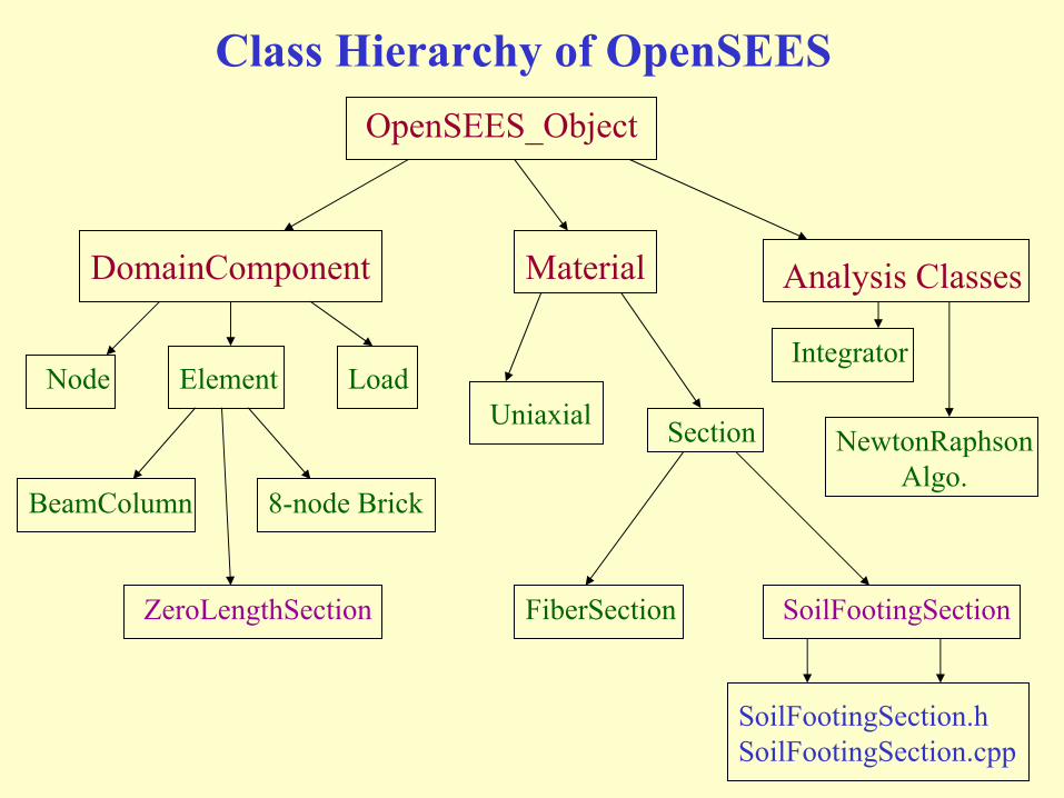
Class Hierarchy of OpenSEESOpenSEES_Object
DomainComponent Material Analysis Classes
Node Element LoadUniaxial Section
SoilFootingSectionFiberSection
Integrator
BeamColumn
ZeroLengthSection
8-node Brick
SoilFootingSection.hSoilFootingSection.cpp
NewtonRaphsonAlgo.

A Simple OpenSEES Analysis
V
O
H

A Simple OpenSEES Analysis

OpenSEES Analysis (George Hu)
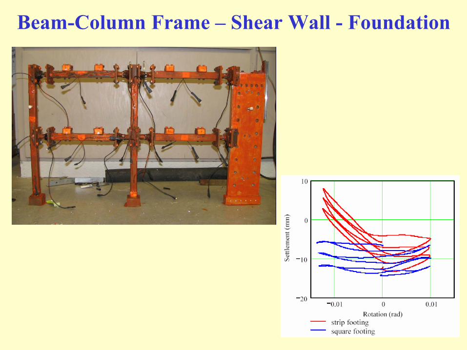
Beam-Column Frame – Shear Wall - Foundation
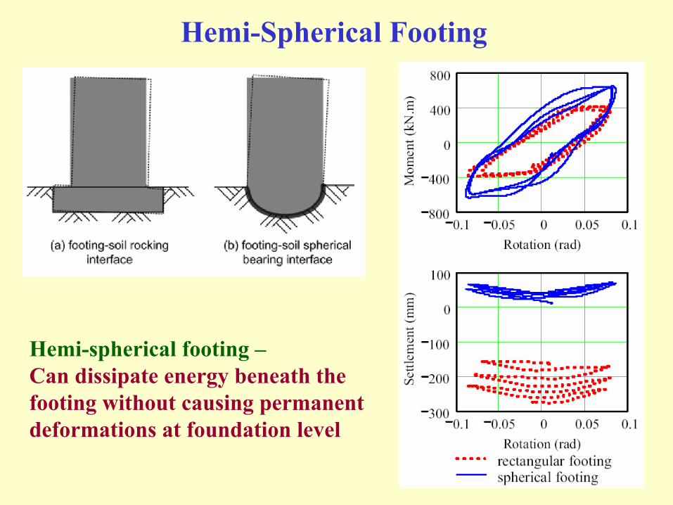
Hemi-Spherical Footing
Hemi-spherical footing –Can dissipate energy beneath thefooting without causing permanentdeformations at foundation level

Experimental FindingsMoment-rotation and shear-sliding relationships
Depends on initial vertical static factor of safety (FSV)Controlled by material (soil yielding) and geometrical (footing uplift)
nonlinearitiesMoment capacity does not degrade with cycling, but rotational stiffness
does degrade (due to rounding of the interface and uplift of footing)
Settlement, sliding and rotationSettlement and sliding continue to accumulate with the number of cycles
of rotation, though the rate decreases as the footing embeds itselfApplied moment to shear ratio (height of center of gravity of the
structure) controls the ratio of rotation to sliding at the interface
The results show that yielding of soil beneath the footing causes a large amount of energy dissipation
Reduces shaking demands on the super structureCauses undesired permanent deformations at the foundation

Footing-Soil “Interface-Element”
Model is based on the physics, geometry and mechanism of the problem and is computationally fast
Coupled force-displacement relationships in (V-H-M) space
Only 4 major model parameters
No need for external mesh generation
Reproduces the load-displacement behavior observed in the experiments
Can be used independently as well as with other structural models to analyse soil-foundation-structure interaction problems