modeling of common-mode currents on electric ship architectures mississippi state university...
TRANSCRIPT

Modeling of Common-mode Currents on Electric Ship
ArchitecturesMississippi State University
Department of Electrical and Computer Engineering
Michael Mazzola and Maryam Rahmani
Presented by Michael Mazzola This work was supported by the Office of Naval Research as part of the Electric Ship Research and Development Consortium under Grant N00014-08-1-0080.

Michael MazzolaAngela Card
Student:Maryam Rahmani
Grounding Team
Lukas Graber (lead)Mischa SteurerJozef Kvitkovic
Student:Patrick Breslend
Steve Pekarek
Students:Aaron Brovont
External Collaboration: W. Blake, B. Hood, K. Watts
310 Aug 2014
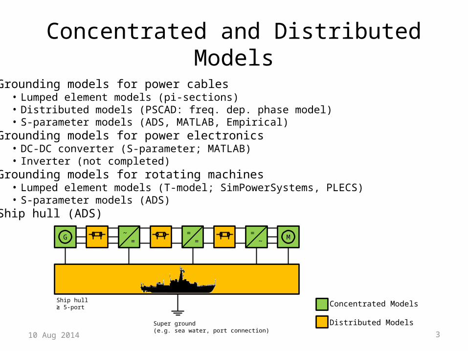
Concentrated and Distributed Models
G ~=
==
=~ M
Ship hull≥ 5-port
Super ground(e.g. sea water, port connection)
Concentrated Models
Distributed Models
• Grounding models for power cables• Lumped element models (pi-sections)• Distributed models (PSCAD: freq. dep. phase model)• S-parameter models (ADS, MATLAB, Empirical)
• Grounding models for power electronics• DC-DC converter (S-parameter; MATLAB)• Inverter (not completed)
• Grounding models for rotating machines• Lumped element models (T-model; SimPowerSystems, PLECS)• S-parameter models (ADS)
• Ship hull (ADS)

Common-Mode Current on the Hull and Bulkheads
• Demonstrate behavioral modeling tools for hull and interconnected grounded conductors derived from physics based simulation. – Many grounded conductors bonded to hull and forming interconnected
network on which common-mode current is impressed (e.g., cable sheaths)– Model with multi-port system based on, or derived from, S-parameters– ADS computes S-parameters for hull & bulkhead geometries with N bonds– Network analyzer measures three-terminal S-parameters for cables– Synchronizing reference potential requires careful thought

S-Parameters of Open-Form Conductor Systems

•Reference plane•Air = 50 mm•“Steel” = 25.4 mm•“Paint” = 1 mm•“Seawater” = 100 mm
Physics based calculation of S-parameter model of a four-port square block in Agilent ADS• Finite element analysis with auto-generated mesh• Frequency range is zero to 10 MHz

Physics based calculation of S-parameter model of elementary rectangle in ADS• Finite element analysis with auto-generated mesh• Edge ports to interconnect elementary rectangles to form
a single square• Frequency range is zero to 10 MHz
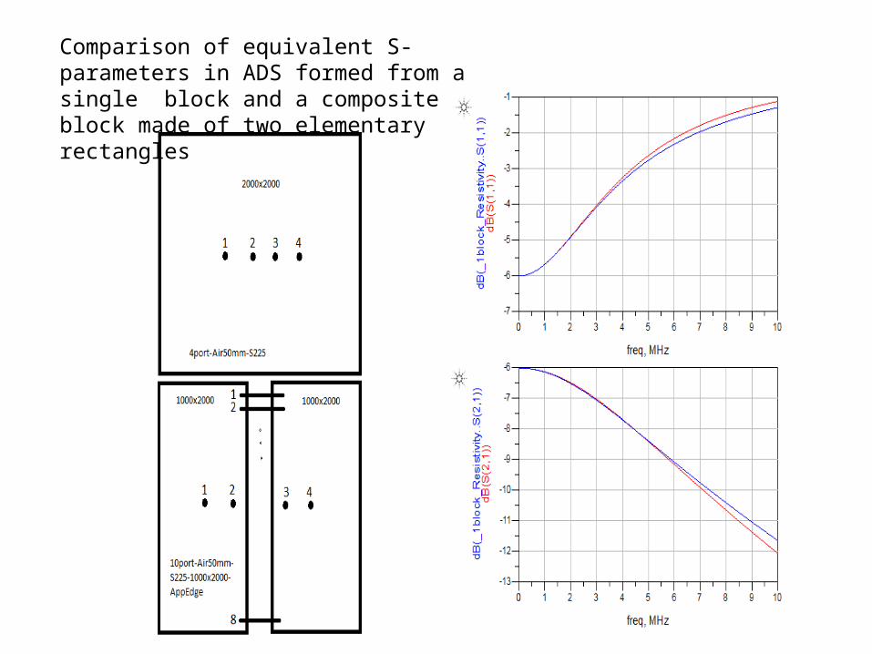
Comparison of equivalent S-parameters in ADS formed from a single block and a composite block made of two elementary rectangles
1 2 3 4 5 6 7 8 90 10
-22.8
-22.6
-22.4
-22.2
-23.0
-22.0
freq, MHz
dB(S
(2,1
))dB(_
11port
_A
ir50m
m_H
exagon_A
ppEdge_4_cacaded_FEM
..S(2
,1))
1 2 3 4 5 6 7 8 90 10
-1.0
-0.9
-0.8
-0.7
-1.1
-0.6
freq, MHz
dB(S
(1,1
))dB(_
11port
_A
ir50m
m_H
exagon_A
ppEdge_4_cacaded_FEM
..S(1
,1))
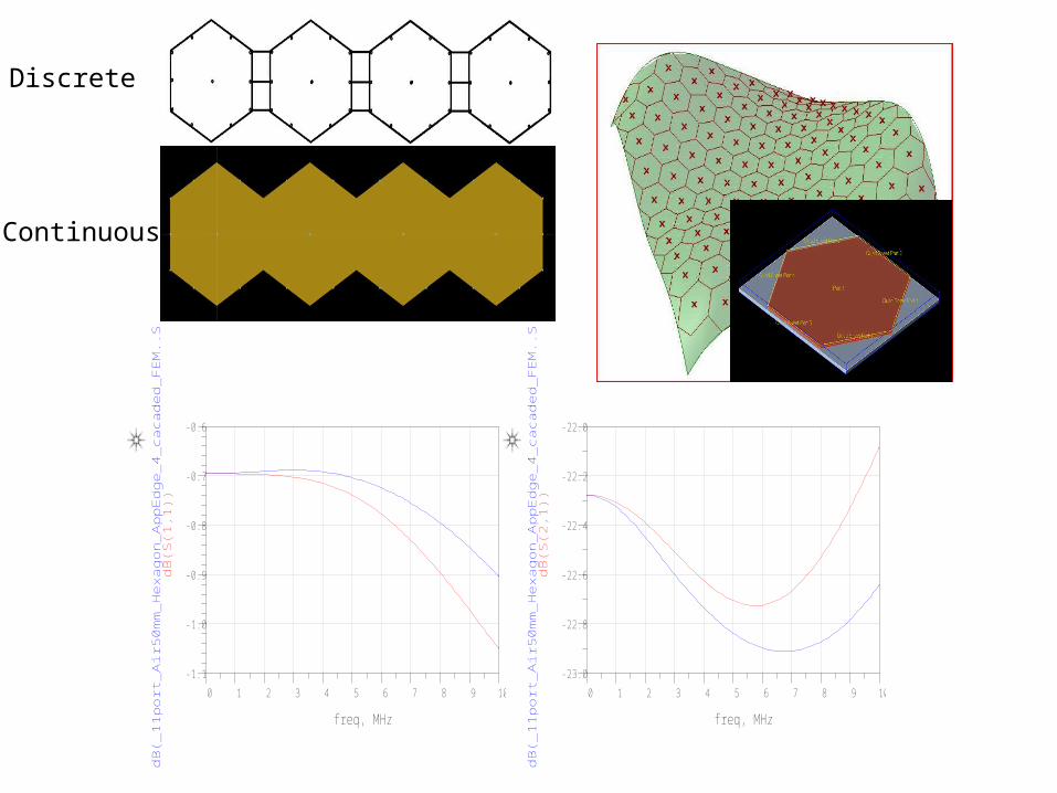
Discrete
Continuous
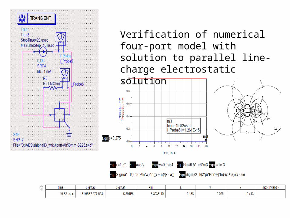
Verification of numerical four-port model with solution to parallel line-charge electrostatic solution
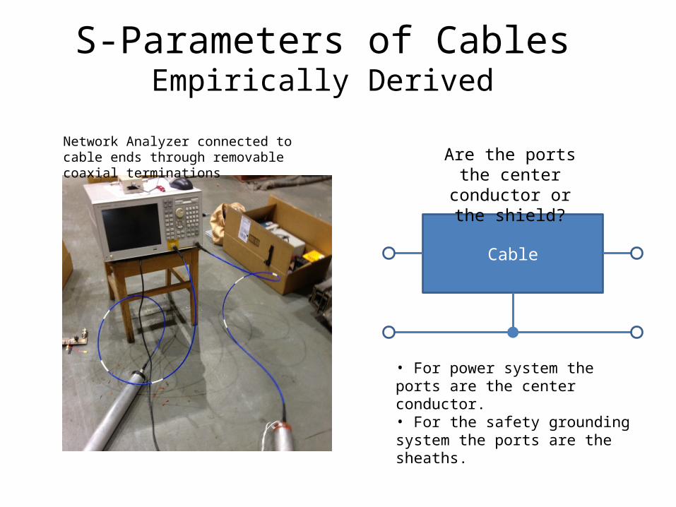
Network Analyzer connected to cable ends through removable coaxial terminations
S-Parameters of CablesEmpirically Derived
Cable
Are the ports the center conductor or
the shield?
• For power system the ports are the center conductor.• For the safety grounding system the ports are the sheaths.

S-Parameters of CablesEmpirically Derived
Cable
S-parameter model is symmetrical
• Measure at center conductor.• Reference third terminal at: • Hull potential in power system
simulation• Power bus potential in hull
system simulation.
center conductor
shield conductor
Summary• Ship power systems are evolving in complexity to the
point where design automation is essential.• Simulation and modeling of a large open-form
conductor system (ship) using finite element analysis too cumbersome for early stage design.
• Problem can be solved by converting to behavioral models derived from physics-based modeling supplemented with empirical data.
• “Arbitrary” open-form conductor systems built up from elementary behavioral models.