modeling of a pulsed high magnetic field solenoid for...
TRANSCRIPT

UNIVERSITY of CALIFORNIA
SANTA CRUZ
MODELING OF A PULSED HIGH MAGNETIC FIELD SOLENOIDFOR ION BEAM FINAL FOCUS
A thesis submitted in partial satisfaction of therequirements for the degree of
BACHELOR OF SCIENCE
in
PHYSICS
by
Heaven L. Hodges
4 October 2010
The thesis of Heaven L. Hodges is approved by:
Frank BieniosekAdvisor
Professor David P. BelangerTheses Coordinator
Professor David P. BelangerChair, Department of Physics

Copyright c© by
Heaven L. Hodges
2010

Abstract
Modeling of A Pulsed High Magnetic Field Solenoid for Ion Beam Final Focus
by
Heaven L. Hodges
The operational details of a proposed pulsed high magnetic field (50 T peak field
strength) solenoid with flux excluder are explored. This device will be used for final
focusing of the Li+ particle beam that will be delivered by the upcoming NDCX-II
induction accelerator at Lawrence Berkeley National Laboratory. Using the Pois-
son/Superfish Group Codes, peak field strength along the longitudinal axis, focal
length, and pulse length were explored for a range of flux excluder geometries. Ge-
ometry variables included thickness (ranging from 0.5 mm to 4.5 mm) and the length
of the excluders inner surface (ranging from 0.5 mm to 10 mm), while the outer ra-
dius and outer length were held constant at 5 mm and 10 mm, respectively. Results
show that a thick flux excluder with a nearly triangular side perspective maximizes
on-axis field strength and minimizes focal length (≈ 0.108 m); optimal measurements
consisted of a thickness of 4.5 mm and an inner surface length of 0.5 mm. Scaling of
all experimental field strength values such that this excluder has a peak on-axis field
strength of 50 T suggests that ≈ 79, 452 A peak current must be achieved to drive the
field. Field penetration of less than a tenth of the excluder’s thickness necessitates
a pulse length that is significantly less than 0.58 µs if the concentrator is made of
stainless steel and significantly less than 2.8 µs for a tungsten excluder.


v
Contents
List of Figures vi
Dedication vii
Acknowledgements viii
1 Introduction 1
2 Method 6
3 Results 12
4 Conclusion 18
A Sample Automesh Input File 20
Bibliography 22

vi
List of Figures
1.1 Flux Excluder: Head-On Perspective . . . . . . . . . . . . . . . . . . 51.2 Flux Excluder: Half Longitudinal Slice . . . . . . . . . . . . . . . . . 5
2.1 Primary In Poisson Graphical Output with z = 30 mm by r = 45 mmOuter Geometry . . . . . . . . . . . . . . . . . . . . . . . . . . . . . . 7
2.2 Primary with Pulsed Magnetic Field . . . . . . . . . . . . . . . . . . 92.3 Primary with Steady-State Magnetic Field . . . . . . . . . . . . . . . 10
3.1 Comparison of On-Axis Magnetic Field Strength Distributions of Pri-mary, Least Efficient Excluder, and Most Efficient Excluder . . . . . 13
3.2 Peak Field Strength On-Axis vs. L . . . . . . . . . . . . . . . . . . . 143.3 Peak Field Strength On-Axis vs. d (1 mm ≤ L ≤ 5 mm) . . . . . . . 153.4 Peak Field Strength On-Axis vs. d (5 mm ≤ L ≤ 10 mm) . . . . . . 163.5 Focal Length . . . . . . . . . . . . . . . . . . . . . . . . . . . . . . . 17
4.1 Optimal Flux Excluder Geometry in Poisson Graphical Output . . . 19

vii
Dedicated to Pascale Courtens
who,
in exhibiting interest in this project
despite a profound lack of understanding,
exemplified the nature of a true scientist.

viii
Acknowledgements
This research was accomplished at the Accelerator and Fusion Research Division of
Lawrence Berkeley National Laboratory in Berkeley, CA between June 7 and August
13 of 2010 as a Science Undergraduate Laboratory Internship (SULI) project. The
project was mentored by staff scientist Frank Bieniosek, with additional advising and
inspiration provided by Enrique Henestroza. I thank the U.S. Department of Energy,
the Center for Science and Engineering Education (CSEE) and LBNL for establishing,
funding, and organizing the program.

1
1
Introduction
As part of the Virtual National Laboratory for Heavy-Ion Fusion Science (HIFS-
VNL) collaboration, the HIFS research group at Lawrence Berkeley National Labo-
ratory (LBNL) is charged with contributing to the realization of controlled nuclear
fusion for the ultimate goal of relatively inexpensive, readily available, non-toxic en-
ergy production. The group uses heavy-ion inertial confinement to drive the fusion
of the plentiful hydrogen isotopes deuterium and tritium. In a single reaction of this
kind, a small, frozen pellet of the deuterium and tritium ”fuel” is housed in a Hol-
raum metal shell and rapidly heated by intense ion beams from the Neutralized Drift
Compression eXperiment (NDCX) induction particle accelerator. X-rays emitted by
the heated Holraum shell compress the fuel pellet to such an extent that the fuel
nuclei within fuse and release relatively large amounts of energy.
The achievement of this nuclear reaction is predicated upon the ion beam intensity.
The positively charged lithium ions form a space-charge dominated beam that is

2
subject to spatial spread due to the electrically repulsive forces between the particles.
Random thermal motion and thermal energy imparted by the ion source also affect
beam spread. As ion beams from the NDCX lack the intensity to drive inertial fusion
reactions, a new pulsed high magnetic field solenoid is being planned in anticipation
of the projected 2012 arrival of the NDCX-II. NDCX and NDCX-II primarily utilize
a negatively-charged plasma region to neutralize space charge repulsion. Fine radial
focusing of the beam is subsequently accomplished with a pulsed, high magnetic field
solenoid through which the beam passes near the end of its progress through the
accelerator tube.
As the ion beam enters the solenoid (with a primarily longitudinally-directed
velocity), the radial component of the cylindrically symmetric magnetic field imparts
an azimuthal acceleration to the ion beam charge q according to the Lorentz Force
Law (in cylindrical coordinates):
~Fφ = q(vz z ×Brr) (1.1)
Further along in the solenoid, where the longitudinal component dominates, the spi-
raling particles experience a radial force:
~Fr = q(vφφ×Bz z) (1.2)
and the resulting inward acceleration of the ions achieves radial compression of the
beam, increasing the power per unit area delivered to the target.
3
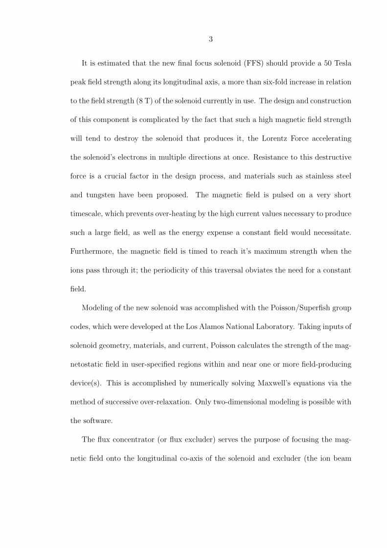
It is estimated that the new final focus solenoid (FFS) should provide a 50 Tesla
peak field strength along its longitudinal axis, a more than six-fold increase in relation
to the field strength (8 T) of the solenoid currently in use. The design and construction
of this component is complicated by the fact that such a high magnetic field strength
will tend to destroy the solenoid that produces it, the Lorentz Force accelerating
the solenoid’s electrons in multiple directions at once. Resistance to this destructive
force is a crucial factor in the design process, and materials such as stainless steel
and tungsten have been proposed. The magnetic field is pulsed on a very short
timescale, which prevents over-heating by the high current values necessary to produce
such a large field, as well as the energy expense a constant field would necessitate.
Furthermore, the magnetic field is timed to reach it’s maximum strength when the
ions pass through it; the periodicity of this traversal obviates the need for a constant
field.
Modeling of the new solenoid was accomplished with the Poisson/Superfish group
codes, which were developed at the Los Alamos National Laboratory. Taking inputs of
solenoid geometry, materials, and current, Poisson calculates the strength of the mag-
netostatic field in user-specified regions within and near one or more field-producing
device(s). This is accomplished by numerically solving Maxwell’s equations via the
method of successive over-relaxation. Only two-dimensional modeling is possible with
the software.
The flux concentrator (or flux excluder) serves the purpose of focusing the mag-
netic field onto the longitudinal co-axis of the solenoid and excluder (the ion beam

4
path). It is therefore expected to increase the on-axis field strength, magnifying the
effect that the solenoid alone would produce. The excluder will be air-insulated from
the surrounding current-carrying coil. Viewed head-on (Fig. 1.1), the component
resembles a hollow cylinder, but is unique in the design of its inner walls, whose
length along the longitudinal axis varies with radial distance from the longitudinal
axis. Visualizing the longitudinal slice in Fig. 1.2 revolved 360 degrees about the axis
along which the inner length L lies clarifies this shape. The excluder also features a
1 micron wide cut that will force a return current to flow over the its inner surface
in a direction opposite to that induced to flow over its outer surface. Estimations
suggested a 10 mm outer length for the device. The outer radius was set at 5 mm.
Variables explored in this investigation include the distance required to focus the ion
beam (focal length) as a function of the driving current (via the induced magnetic
field), and an upper limit on the appropriate pulse length of the driving current given
two proposed construction materials, stainless steel and tungsten.

5
Figure 1.1: Flux Excluder: Head-On Perspective
Figure 1.2: Flux Excluder: Half Longitudinal Slice

6
2
Method
Due to the limited directions for current flow specification available in Poisson,
the primary and flux concentrator were modeled from a side perspective only. A
condition of cylindrical symmetry about the (vertical) z-axis was specified to simulate
the three-dimensional nature of the physical problem, and thus only one half of the
side perspective of the geometry appears in the output images.
The primary was modeled as a thin, rectangular tube (Fig. 2.1), 0.1 mm thick by
10 mm long, located a radial distance of 0.1 mm from the excluder. Revolved about
the z axis, this model would form a single-turn coil, and was therefore expected to
provide a field strength distribution closely approximating such a coil. The accuracy
of Poisson’s magnetic field strength calculations for the primary alone was verified by
comparison with values predicted by [3]:
B(ζ) = µ0NI
2βa
Γ(α, β + ζ) + Γ(α, β + ζ)
2(2.1)

7
Figure 2.1: Primary In Poisson Graphical Output with z = 30 mm by r = 45 mmOuter Geometry
where N is the number of turns (1), I is the current input(1 A), a is the inner
radius of the coil (5.1 mm), 2βα is its length (10 mm), αa is its outer radius (5.2
mm), z = aζ is the distance from z=0, and
Γ =β
α− 1lnα +
√α2 + β2
1 +√
1 + β2(2.2)
As Poisson is only capable of steady-state simulations, only the peak of the pulsed
field was modeled. A magnetic field that is pulsed with sufficient rapidity will pene-
trate the excluder very little, and the field within the flux excluder boundary would
be zero. The condition of minimal penetration was simulated by setting the excluder
boundary to a fixed vector potential (input parameter IBOUND=-1, see Appendix
A). The value specified for this potential (input parameter CUR) was also inter-
preted by Poisson as the magnitude of the total current on the flux excluder surface.

8
Poisson altered the field due to this surface current to create the constant surface
potential; this in turn altered the field distribution (in relation to the field that would
have existed without the IBOUND specification). It was therefore necessary to scale
the on-axis field strength magnitude (there was little concern with the off-axis field
aside from its realism) at each of the chosen sample points z such that, according to
Ampere’s Law ∫∞∞ Bzdz
µ0
was constant across all Poisson trials, as it was desired to run all trials with the same
peak driving current.
It is expected that the on-axis value of∫Bzdz for the flux excluder approach
the value of the same for the primary alone in the limit d → 0. After the afore-
mentioned scaling in accordance with Ampere’s Law, there was a discrepancy of a
factor of approximately 11 between the values of this integral for the coil and for the
trial excluders for which d=0.5 mm (interpreted as an approximation to d=0). This
necessitated the specification of a fixed potential over the surface of the primary as
well, which ameliorated the discrepancy by increasing∫Bzdz for the primary by a
factor of about 9.56. The physical significance of this simulation detail (zero field
penetration within the coil due to a pulsed field) not only increased the realism of the
simulation, but is desirable from a design perspective. Figs.s 2.2 and 2.3 show the
difference in field configuration of the coil with and without magnetic flux excluded.
All magnetic field strength values were then scaled such that the peak on-axis field
strength of the best field-concentrating excluder was equal to 50 T. Ampere’s Law
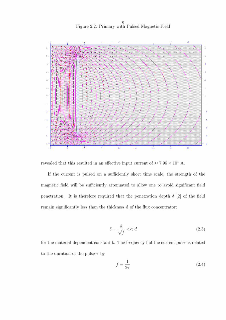
9Figure 2.2: Primary with Pulsed Magnetic Field
revealed that this resulted in an effective input current of ≈ 7.96× 10⁴ A.
If the current is pulsed on a sufficiently short time scale, the strength of the
magnetic field will be sufficiently attenuated to allow one to avoid significant field
penetration. It is therefore required that the penetration depth δ [2] of the field
remain significantly less than the thickness d of the flux concentrator:
δ =k√f<< d (2.3)
for the material-dependent constant k. The frequency f of the current pulse is related
to the duration of the pulse τ by
f =1
2τ(2.4)

10
Figure 2.3: Primary with Steady-State Magnetic Field
Equations 2.3 and 2.4 lead to the relationship:
τ <<d2
2k2(2.5)
For stainless steel, k = 0.417; for tungsten, k = 0.189.
Flux excluder geometry was varied to determine it’s effect on magnetic field
strength. While holding the outer radius constant at 5 mm, the radial thickness
of the excluder, d, ranged from 0.5 mm to 4.5 mm in 0.5 mm increments. The length
of the shorter base in the trapezoidal side perspective, L, varied from 0.5 mm to 10
mm in 0.5 mm increments (Figure 1.2). The combination of these two variables pro-
duced a total of 180 physically distinct possible flux excluders. The Poisson/Superfish

11
post-processor SF7 supplied the values of Bz at 1000 evenly-spaced intervals along
the longitudinal axis (−100 mm < z < 100 mm) in each of these trials. These values
were then used to calculate the focal length [1],
f =4∫ [
qBz(0,z)γm0vz
]2dz
(2.6)
where m0 is the relativistic mass of the ions (Li+), vz is their longitudinal velocity,
and γ is the Lorentz factor. The latter two constants were calculated using the ion
kinetic energy of 2 MeV . The charge q of one ion is 2e.
12
3
Results
While agreement between experimental and theoretical field strength values for
the primary was very good for on-axis points near the origin, over 50% of the points
at which the field strength was sampled disagreed with Equation 2.1 with greater
than 20% error, regardless of the number of points sampled. Due to the feature of
Poisson that forces the magnetic field strength to approach zero near the limits of
the outer geometry, this was especially true near z = ±100 mm, where relative error
exceeded several hundred percent, in comparison with about 2.5% relative error at
z = 0. Equationtheory does not apply to a pulsed primary, and so there was no
agreement after scaling of the field strength values via Ampere’s Law.
Figure 3.1 illustrates the expected increase in magnetic field strength afforded by
the inclusion of a flux excluder in the solenoid construction. The factor of increase of
peak on-axis (Bz=0) field strength ranged from ≈ 1.03 (for L=10, d=0.5) to ≈ 8.02
(L=0.5, d=4.5).

13
Figure 3.1: Comparison of On-Axis Magnetic Field Strength Distributions of Primary,Least Efficient Excluder, and Most Efficient Excluder

14
Figure 3.2: Peak Field Strength On-Axis vs. L
The relationship between peak on-axis field strengths for the 180 different geome-
tries can be seen in Figs.s 3.2, 3.3 and 3.4.
The peak field as a function of d for L=0.5 mm through L=5 mm is presented in
Fig. 3.3. Figure 3.4 shows the same relationship for L=5.5 mm through L=10 mm.
Figure 3.5 shows the variation of focal length as a function of L.

15
Figure 3.3: Peak Field Strength On-Axis vs. d (1 mm ≤ L ≤ 5 mm)

16
Figure 3.4: Peak Field Strength On-Axis vs. d (5 mm ≤ L ≤ 10 mm)

17
Figure 3.5: Focal Length

18
4
Conclusion
The substantial disagreement between experimental and theoretical (Equation 2.1)
field strength calculations suggests an increase in the size of the outer geometry (with
respect to the solenoid and flux excluder) and the number of sample points along
the longitudinal axis as much as possible in any future investigations of a DC-driven
primary.
As it is clear from Fig. 3.1 that the inclusion of a flux concentrator will increase the
efficiency of the proposed FFS, it remains to decide on the details of the construction
of the device. The dependence of the peak field strength on the parameter d suggests
that the thickest flux concentrator that is practical would maximize the field on-axis.
Further investigation should take into account the minimum radius of the aperture
necessary for beam traversal, as the possibility of beam interaction with the current-
carrying walls of this aperture is undesirable.
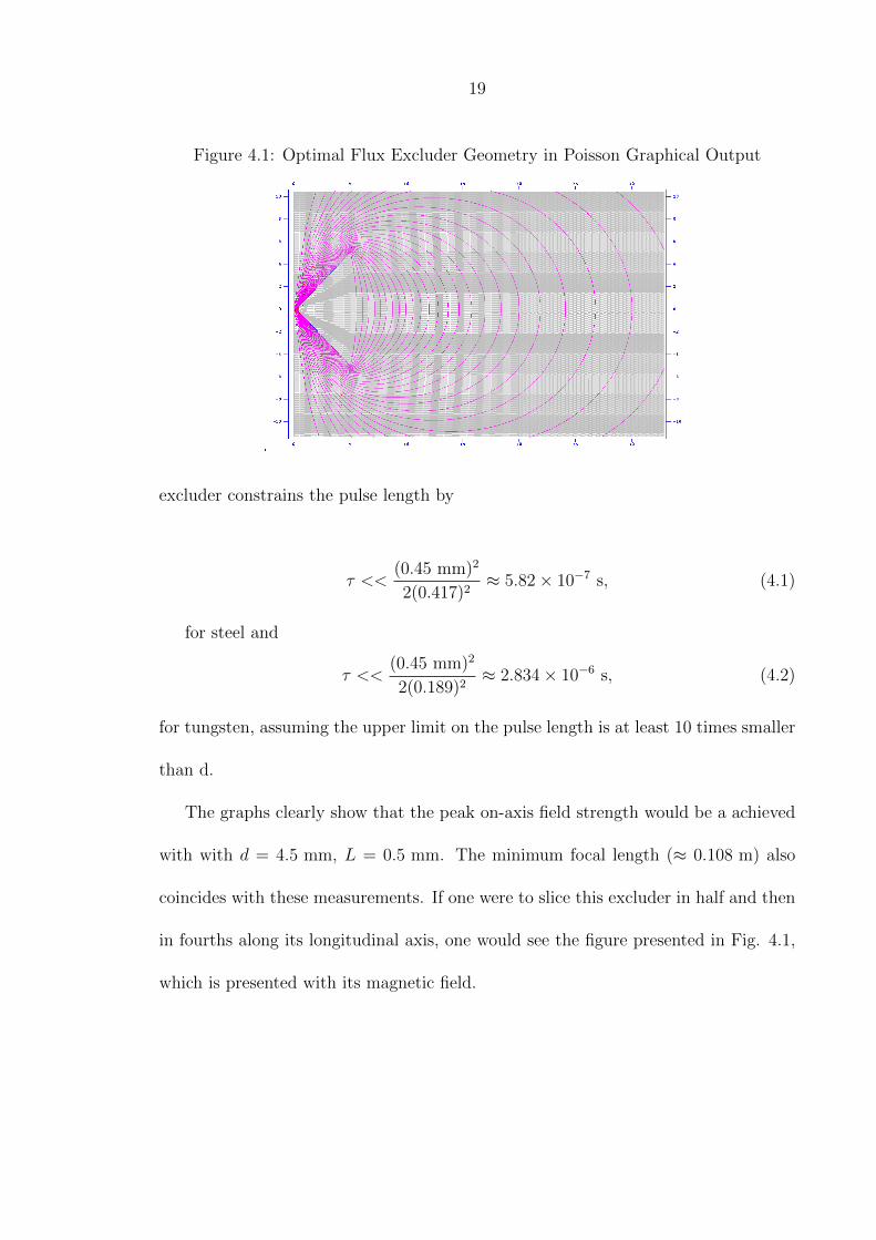
According to Equation 2.5, taking d=4.5 mm as the appropriate thickness of the
19
Figure 4.1: Optimal Flux Excluder Geometry in Poisson Graphical Output
excluder constrains the pulse length by
τ <<(0.45 mm)2
2(0.417)2≈ 5.82× 10⁻⁷ s, (4.1)
for steel and
τ <<(0.45 mm)2
2(0.189)2≈ 2.834× 10⁻⁶ s, (4.2)
for tungsten, assuming the upper limit on the pulse length is at least 10 times smaller
than d.
The graphs clearly show that the peak on-axis field strength would be a achieved
with with d = 4.5 mm, L = 0.5 mm. The minimum focal length (≈ 0.108 m) also
coincides with these measurements. If one were to slice this excluder in half and then
in fourths along its longitudinal axis, one would see the figure presented in Fig. 4.1,
which is presented with its magnetic field.

20
Appendix A
Sample Automesh Input File
Flux Concentrator with Surface Current (Side Perspective)
$REG KPROB=0,
ICYLIN=1,
DX=0.025,
DY=0.025,
NBSLF=0,
NBSLO=0,
YREG=-50.0, -15.0, 15.0, 50
LREG=0, 50, 210, 510, 670
LMAX = 720
XREG=20.0, 50
KREG=0, 200, 550
KMAX=600
CONV=0.1 &
&PO X=0.0, Y=-100.0 &
&PO X=100.0, Y=-100.0 &
&PO X=100.0, Y=100.0 &
&PO X=0.0, Y=100.0 &
&PO X=0.0, Y=-100.0 &
® CUR=1 IBOUND=-1 &
;flux concentrator
&PO X= 0.5 ,Y= -0.25 &

21
&PO X= 5 ,Y= -5 &
&PO X= 5 ,Y= 5 &
&PO X= 0.5 ,Y= 0.25 &
&PO X= 0.5 ,Y= -0.25 &

22
Bibliography
[1] S. Humphries, Jr. Principles of Charged Particle Acceleration. New York: John
Wiley & Sons, 1986, pp. 127.
[2] S. Ramo, J. Whinnery, and T. Van Duzer, Fields and Waves In Communication
Electronics. New York: John Wiley & Sons, Inc., 1965, pp. 289.
[3] F. Herlach Pulsed Magnets. New York: John Wiley & Sons, Inc., 1965, pp. 864.