modeling issues associated with sensor technologies for
TRANSCRIPT

Northland Advanced Transportation Systems Research Laboratories
Modeling Issues Associated with Sensor Technologies for the Nondestructive Evaluation of Timber Bridges.
Final Report
July, 2006
Harlan Stech Zhuangyi Liu
Steven Trogdon Guihua Fei
University of Minnesota Duluth Department of Mathematics and Statistics
140 Solon Campus Center Duluth, MN 55812

2
Table of Contents
Executive Summary ……………………………………………………………….. 3 Chapter 1: Background ………………………………..………………………….. 4 Chapter 2: Reference Models ………………………………..…………………….. 7 Chapter 3: The Effects of Nonlinear Boundary Conditions ..…..…………..…... 14 Chapter 4: Point-Loaded Spans ………………………………..……….………... 26 Chapter 5: Conclusions and Recommendations ……………..……….…….….. 31 Chapter 6: Recommended Problems for Further Study …....……….…...…….. 34 Acknowledgements …………………………………………………………….….. 36 References …………...………………………………………………………….….. 36
Key Words: Nondestructive evaluation, timber bridges, beam and plate models, modal analysis,
flexural vibration, vibrational sensors.

3
Executive Summary: This report documents progress made in the development and validation of a class of models examining the reliability of proposed vibrational inspection tests of single-spanned bridges. The overall goal of the work was to obtain a better understanding the effects of various bridge architectures and reductions of bridge integrity on the vibrational characteristics of single bridge spans. This work was motivated by testing methods under development through cooperative research between the UMD Natural Resources Research Institute, Michigan Technological University and the USDA Forest Products Laboratory (Madison, WI). These researchers have proposed to derive estimates of bridge strength indirectly by relying on theoretical relationships connecting bridge strength and motion sensor data measured on bridges subject to controlled forced vibrations. Project investigators have collaborated with NRRI and Forest Service staff in the interpretation of field-test data and in identifying the key architectural assumptions for the derived mathematical models. This work has contributed to the theoretical basis for the development of new motion detection sensor technologies addressing the problem of monitoring and estimating bridge integrity. Following a review of the literature regarding mathematical models of bridge structures and their vibrational characteristics, two important problems were identified for special consideration. The first concerned the development of a mathematical formulation of the nonlinear boundary conditions needed to accurately model the end support structures of single-span (stringer-based) timber spans. A computational algorithm for the numerical approximations of such systems was derived, implemented and tested using the commonly available Mathematica software package. The second focal problem involved the modeling and analysis of a newly-proposed vibrational testing method. The method (motivated by a similar testing method currently being used by the Institute of Public Works Engineering Australia) seeks to predict bridge strength from vibrational data, and (most importantly) without the need to estimate overall bridge mass. Models developed in this project have contributed to a mathematical understanding of these issues, as well as the creation of a new bridge testing protocol involving the measurement of bridge vibrational responses to forced vibrations both with and without controlled loading. Besides the outreach motivation for this work, the project has provided important opportunities for participation by students in the UMD Program in Applied and Computational Mathematics, illustrating real-world uses of modeling, computation, visualization, data analysis, as well as the process of consultation with professionals on transportation-related issues.

4
Chapter 1: Background Literature Review The maintenance of a safe vehicular bridge system is a critically important component of our nation’s transportation system. In 2000 the Federal Highway Association [FHWA] National Bridge Inventory Program [1] cited 1,712 highway bridges of a total 11,191 in Minnesota to be classified as either structurally deficient or functionally obsolete. While most new bridge structures rely on steel and concrete, there is a significant base of older wooden bridges whose architectural designs have undergone numerous changes [31] over the years. At the present time, approximately 41,750 timber bridges (with a span of 20 ft or more) are in service nationally, with an average age of 40 years. Additionally, there are numerous short single span bridges and culverts that are ideal candidates for replacement with pre-fabricated, single-span, timber installations [23]. Bridges in northern Minnesota are subject to difficult environmental conditions, leading to deterioration due to weathering and mechanical failures, as well as material-specific modes of aging. A variety of nondestructive evaluation (NDE) methods have been proposed as a means of improving the reliability of bridge inspections [4]. The goal of these techniques is to supplement the most common visual inspection and hammer sounding methods with newer, quantitative approaches that do not rely so heavily on the inspector’s judgment [2-7, 32, 33]. Motivated by methods developed for testing wood flooring systems, the UMD Natural Resources Research Institute, Michigan Technological University and the USDA Forest Products Laboratory have recently initiated the assessment of bridge integrity though the measurement of natural frequency information. Vibrational tests are considered to be a first-pass method, identifying structures that need further inspection [24]. The theoretical justification of this approach has been based on the observation that if one models a single-spanned timber bridge as a Bernoulli beam with simply-supported (un-clamped) boundary conditions, then one can derive an algebraic formula that relates bridge strength characteristics (modulus of elasticity, E), bridge mass, physical dimensions, and the frequency of the bridge’s primary bending mode of oscillation [8]. The latter can be easily measured with a test that uses an electric motor with a rotating unbalance to excite the structure. Bridge vibrational responses can be accurately measured with commonly available piezoelectric crystal type accelerometers. This type of test is preferable to measuring bridge strength by observing bridge deflections under controlled static loading due to its simplicity of implementation and resulting low cost. Furthermore, for bridges in high-traffic areas, it is disruptive to close them for the time interval required for static load testing. Wood products researchers at Michigan Technological University and the Wood Products Laboratory (Madison, WI) of the USDA Forest Service have tested numerous field bridges in the Ottawa Chequamegon-Nicote National Forests, Northern Minnesota, as well as laboratory installed bridges, using forced vibrational tests [9, 36]. Their early work raised questions regarding the appropriateness of a using a simple Bernoulli-beam type model, as well as concerns about the boundary conditions assumed to accurately reflect a variety of span construction techniques. Furthermore, field testing had shown that in many cases the first (lowest) observed bridge response frequency, which the classical Bernoulli beam theory predicts will be associated with needed bending mode, was in fact associated with a torsional mode of oscillation not predictable with the Bernoulli model. Researchers at the USDA Forest Service

5
Forest Products Laboratory (Madison, WI) and UMD NRRI suggested the need for better understanding the torsional modes of oscillation in simple beam structures, as well as the impact of various “boundary condition” assumptions on span theoretical vibrational characteristics [10, 36]. Project Overview: The first stage of this investigation focused on performing a thorough literature review of recent mathematical modeling research related to assessing bridge integrity from forced-vibrational inspection tests. The current status and progress of modeling techniques, especially those related to beam type models, has been reviewed, with special attention given to Timoshenko beam theory, modal analysis, and beam models with locally applied mass. Meetings were held with Brian Brashaw (Program Director, Forest Products Division, Natural Resources Research Institute) to discuss the experimental measurements of bridge spans, as well as to become more familiar with the most common forms of timber bridge architectures, their most likely modes of degradation, and current bridge inspection methods. Project investigators toured NRRI laboratory facilities, and observed laboratory tests of an installed single span (stringer + transverse-planked) bridge span. Project investigators also observed field vibrational testing of three single span bridges located in St. Louis County, MN, and met with staff of the University of Minnesota Natural Resources Research Institute and USDA Forest Service regarding field testing procedures, bridge architectural design, testing methodologies, bridge degradation types, and modeling alternatives. Project investigators also participated in a meeting (coordinated by Brian Brashaw, NRRI) with the Kenneth Johnson, PE, Wheeler Lumber, LLC (Bloomington, MN) to discuss design and modeling issues related to longitudinal panel bridges. In addition to the three project principal investigators (Stech, Liu and Fei), Dr. Steven Trogdon (UMD Department of Mathematics and Statistics) joined the research team and provided important technical expertise and experience related to the modeling of mechanical systems. Two graduate students in the UMD Program in Applied & Computational Mathematics joined the research group in late summer, 2005, and assisted in literature reviews, coding, visualization, modeling, numerical calculations, as well as presenting research results via a poster presentations [22]. Because the investigation was only partially funded, graduate research assistant support was matched by the Department of Mathematics and Statistics of the University of Minnesota Duluth. It should be noted that 100% of the funding for this project was directed to graduate research assistant support, travel and supplies. In particular, faculty participation in this project was unfunded. Based on the collected information, a number of alternative beam-based models of single span bridges have now been developed and analyzed with regard to the expected fundamental modes of oscillation. Project investigators have pursued a variety of alternatives capable of providing insight into torsional modes of bridge oscillation. Timoshenko beam class were determined to be analytically complicated, and justifiably replaced with more straight-forward models in which beam torsional motions are uncoupled from longitudinal bending modes. The use of models associated with different simple bridge span support assumptions has focused on how sensitive predicted bridge modes of oscillation are to such bridge architectural features [22]. A second line of research has considered the possibility of designing a new vibrational testing method that might eliminate the current need to estimate bridge mass from bridge physical

6
dimensions and estimates of material densities. This is of interest because bridge mass is a critical variable needed for the accurate translation of vibrational responses to predictions of bridge strength [9, 24, 36]. In the case of timber structures the determination of bridge mass is complicated by the fact that water content has an impact on wood weight. Because wood water content will vary according to season, it was suggested [9] that vibrational measurements should be accompanied with a representative sample of moisture content readings and a careful measurement of bridge dimensions. Furthermore, if bridge mass is to be estimated from its physical dimensions, effort must be made to either remove surface road materials (eg, accumulated sand and gravel), or to estimate its load contribution. This need significantly increases the complexity and cost of bridge inspections. Related to this issue, the Institute of Public Works Engineering Australia (IPWEA), working in collaboration with the Center for Building Infrastructure Research (University of Technology Sydney), has recently proposed a two-step, impact response test in which bridge oscillation frequencies are measured first for an unloaded span, then for the same span with an applied load. Applying a Bernoulli-beam model [18], that group concludes that one can, with this additional data, eliminate the need for an independent measure of bridge mass [19,20]. However, a serious shortcoming of their work is that they treat the locally applied load mathematically as a uniformly distributed load. This assumption, taken for the purpose of mathematical convenience, requires justification. Furthermore, by modeling their approach with a Bernoulli beam, they have overlooked the possibility that their observed natural frequencies are of torsional, rather than of bending type. In fact, it is quite plausible that the loading procedure they advocate may significantly affect the theoretical bridge mode shapes, necessitating a more careful placement of motion sensors. In connection with this, project investigators have constructed a simple Bernoulli beam model with centrally-attached point mass. We have performed a modal analysis assuming simple (“simply-supported”) boundary conditions, accomplished model validation and calibration (parameter identification) and have completed a vertical (“bending”) and torsional modal analysis. Research Methodology: The basic beam models described in [22] have been generalized through the replacement of simple boundary conditions with conditions more reflective of common bridge architectures. We anticipated nonlinear systems to be encountered, based on the work of [21]. However, the mathematical formulation of beam-based models derived here is significantly different (and more complicated) than the simple models associated with that reference. Consideration was given to models of stringer-based, single-span bridges as a system of weakly connected beams. Examples involving two and three beams illustrate the method and demonstrate that such models are numerically tractable and easily simulated with Mathematica software. Models of periodically-forced, loaded spans have been developed. Numerical methods have been constructed for their simulation. Analytic and numerical analysis of these models suggest that vibrational testing with center-span loading may alleviate the uncertainty associated with bridge mass estimation, as well as providing a way of distinguishing between vertical and torsional modes of vibration.

7
Chapter 2: Reference Models We cite here a few elementary models that are useful for our later discussion. These models are not intended to be viewed as accurate models of bridge spans. However, the first illustrates that vibrational models incorporating the nonlinear nature of span forces may result in complex system behavior that is atypical of related linear systems. The last three (described in detail in [60]) are important limiting cases that are amenable to closed-form algebraic solution. Such cases are important reference points when testing the numerical methods developed for the more accurate models developed as part of this investigation. Simple Mid-Span Deflection Models Perhaps the most elementary model of span vibrations is based on the assumption that vertical deflections at mid-span can be modeled as a simple mass-spring system [33]. Mathematically, such systems are described by the simple linear ordinary differential equation
(2.1) md 2ydt 2
+ bdydt+ ky = F0 cos(2π ft) ,
where t represents time (in seconds), y represents the vertical deflection of the mid-span point from its equilibrium position, m is a measure of span mass, b is a measure of beam damping, and kmodels beam stiffness. The term on the right represent an assumed periodic forcing of the system, with F0 giving the forcing amplitude and f the frequency (measured in cycles per second) of the driving force. It is well-known [38] that in the frictionless, unforced case
(b = 0,F0 = 0 ) the system exhibits a simple sinusoidal motion of the form y(t) = Asin( kmt + φ) ,
with “natural” frequency f0 =12π
km
cycles per second. In the general case, the system
approaches (after transient motions have died out) a similar motion y(t) = A( f )sin( ft + φ)with maximum amplitude vibrations occurring at the “resonance” frequency
(2.2) f0 =12π
km−12
bm
2
.
Under low damping (b ≈ 0 ), the resonance frequency provides a close approximation to the natural frequency of the system. A clear deficiency of this simple model is its implicit assumption that restoring forces for downwards deflections are the same as for upward deflections. For single bridge spans, downwards deflections are expected to elicit a stronger restoring force than for upward deflections, due to the span support structures at the ends of the span. This is illustrated in the following picture of the span end support structure of a timber bridge (observed July, 2005) near Virginia, MN. It is evident that downward pressures of the bridge span have caused damage to the supporting sill plate.

8
Illustration 2.1: The effect of downward deflections on span end support structures.
Typical span end support architecture [33]
Based on this observation, one might consider the nonlinear model
(2.3) md 2ydt 2
+ bdydt+ k(y)y = F0 cos(2π ft) ,

9
where the restoration “constant” is assumed to be larger for downwards deflections ( y < 0 ) than for upwards deflections. See [46] for a related model. However for such nonlinear equations, the closed-form description of system oscillations is no longer available, and our understanding of system motions must rely on numerical simulations in which specific values have been assumed of model coefficients. In the undamped, unforced instance of this system, it is known that all solutions are periodic, although the frequency of the oscillation is dependent on system initial conditions, and is not explicitly describable in closed-form. A phase-plane analysis of this special case shows that system motions are qualitatively the same as the sinusoidal motions found for the simple undamped, unforced linear model. However, in the general model, numerical experiments indicate that the system response to simple sinusoidal forcing may be significantly more complicated than that known for the unforced, undamped case. Moreover, the qualitative nature of system solutions can depend sensitively on the frequency of the forcing term. See [46-51]. We illustrate these assertions by considering the special case in which m = 1 , b = .1and F0 = 1. The term k(y) is assumed to be 3.75 for y > 0 , but three times that value for y < 0. Numerical simulations indicate that regardless of system initial conditions and forcing frequency, f , the system tends to a periodic state after motion transients are allowed to die out. The unforced, undamped system (initiated from rest with initial vertical displacement y(0) = 1 ) is observed to posses a simple periodic motion with frequency near .3753. The damped, forced system, when forced at 71.5% of the natural frequency, is seen to posses the after-transient motion profile shown in Figure 1, below.
The observed output has the same frequency as the forcing frequency, with a profile that is qualitatively the similar to the sinusoidal motion described by the original linear model. However, this profile changes considerably when the forcing frequency of the system is reduced by 2%.

10
Moreover, a 4% reduction of the forcing frequency used in Figure 1 results in a complex motion profile that is significantly different from that predicable from the original linear model.
Although (apparently) periodic, the system response frequency is significantly different from the forcing frequency. Based on these observations, we should not be surprised if more mathematically accurate models of span vibrations demonstrate complex vibrational responses to simple sinusoidal forcing. Despite the lack of analytic solutions for (2.3), numerical simulations suggest that the system possesses many of the general characteristics known for (2.1). With the same parameters as take above, the following illustrates that for small damping, the resonant forcing frequency provides an adequate approximation to the natural frequency (.3753) of the undamped, unforced, model. We take as a measure of output amplitude the classic L2 norm

11
(2.4) x = x2T −ΔT
T
∫ (t)dt / ΔT ,
where T is a large value (typically 1000 times the period, Tref , of a representative driving force) and ΔT is a fixed solution interval (typically 5Tref .)
For m = 1 , b = .1and F0 = 1we provide the natural frequencies of the linear model (2.1) with representative values of spring constant, K .
K Natural Frequency,
Hz 3.75 .3080
7.5= 2*3.75 .4357 11.25=3*3.75 .5337
Recall that in the above simulations k(y) is assumed to be 3.75 for y > 0 , but three times that value for y < 0. The natural frequency of the nonlinear model (2.3) equals .375, which differs significantly from that given by the linear model.

12
The Bernoulli Beam Model with Simply Supported Boundary Conditions As detailed in [60], the classic Bernoulli beam equation is given by (2.5) ρAwtt = −EIwxxxx , where t > 0, 0 <x <L, w = w(x,t) is transverse displacement, L = beam length, E = Young’s modulus, I = Cross-sectional moment of inertia, ρ = mass density and A = cross-sectional area. The simply-supported boundary conditions are given by (2.6) w(0,t) = w(L,t) = 0 and (2.7) wxx (0,t) = wxx (L,t) = 0 The system is linear, and easily solved by the method of separation of variables. The general solution takes the form
(2.8) w(x,t) = cnn=1
∞
∑ cos(2π fnt −θn )sin(νnx / L)
with mode frequencies
(2.9) fn =12π
EIρA(νnL)2
and νn = nπ . The fundamental frequency ( n = 1 ) of the system is
(2.10) f1 =π2
EIρA
1L2
The Bernoulli Beam Model with Fully Clamped Boundary Conditions The Bernoulli beam model with fully clamped boundary conditions consists of the equations (2.5) and (2.6), but with (2.7) replaced by the constraints (2.11) wx (0,t) = wx (L,t) = 0 The system is, as before, solvable by the method of separation of variables. However, the form of the solution is more complicated than that given by (2.8). One has
(2.12) w(x,t) = cnn=1
∞
∑ cos(2π fnt −θn )Xn (νnx / L)
where νn satisfies the transcendental equation (2.13) cos(νn )cosh(νn ) = 1

13
and the mode frequencies are given by (2.9). Solving (2.13) numerically, the fundamental frequency is obtained from
ν1 4.73 , and
(2.14) f1 = 3.56EIρA
1L2
.
See [60] for more information on the mode profiles Xn . The Bernoulli Beam Model with Rotational Spring Boundary Conditions Intermediate to the two previous cases is the situation in which the boundary conditions are of rotational spring type. Here, (2.5) and (2.6) hold, but the system is subject to the conditions
(2.15) wxx (0,t) = kwx (0,t)wxx (L,t) = −kwx (L,t)
,
where k defines the stiffnesses of the two boundary springs (assumed here to be equal.) Formally, k = 0 reduces to problem to the simply-supported case, while k = ∞ gives the fully clamped situation. Once again, the method of separation of variables applies. The general solution takes the form (2.12), where νn = νn (K ) now satisfies the transcendental equation (2.16) K cosh(νn )[−K cos(νn ) + 2νn sin(νn )]+ 2νn sinh(νn )[−K cos(νn ) + νn sin(νn )] = K
2 , with K = kL . The mode frequencies are again given by (2.9), with νn = νn (K ) . Observe that (2.16) reduces to the simply supported case νn = nπ when K = 0 , and gives the fully clamped situation (2.13) when K = ∞ . See [60] for additional details.

14
Chapter 3: The Effects of Nonlinear Boundary Conditions The general consensus among researchers in this area is that the boundary conditions for beam-based models of single bridge spans are of none of the type described above [9]. Because downwards bridge deflections are subject to stronger restoring forces than upwards deflections, one considers models of the type (2.5) with boundary conditions (2.6), and (2.15) modified to account for the nonlinearities at the boundaries. Specifically, (2.15) is replaced by the more general form
(3.1) wxx (0,t) = ko(wx (0,t))wx (0,t)wxx (L,t) = −kL (wx (L,t))wx (L,t)
where k0 (wx ) is a non-increasing function of left ( x = 0 ) boundary orientation and kL (wx ) is a non-decreasing function of right ( x = L ) boundary orientation. The reference [60] considered the special case in which kL ≡ 0 (the beam is simply supported at x = L ), while
(3.2) k0 (wx ) =0,wx ≥ 0K ,wx ≤ 0
with K 0 taken large. Scaling Issues Prior to developing numerical approximation methods for this model, we first perform changes of spatial and time scales in order to reduce the complexity of the problem. Specifically, we
introduced the scaled variables x = x / L and t =tL2
EIρA
. In these new variables, the problem
reads (dropping the bars) (3.3) wtt + wxxxx = 0 where t > 0, 0 <x <1, andw = w(x,t) is subject to boundary conditions (3.4) w(0,t) = w(1,t) = 0 and
(3.5) wxx (0,t) = ko(wx (0,t))wx (0,t)wxx (1,t) = −k1(wx (1,t))wx (1,t)
.
Observe that any solution of (3.3), (3.4), (3.5) with frequency f generates a solution of the unscaled system of frequency

15
(3.6) f = fEIρA
1L2
.
This result points out that the fundamental relationship relating observed span fundamental frequency and span strength applies independently of boundary condition assumptions. Thus, the rationale for using observed span frequency as an indicator of span strength applies to the nonlinear model (3.3), (3.4), (3.5). Specifically, one expects that span strength (as measured by EI ) should be related to observed span fundamental frequency f1 by the relation
(3.7) EI =f12
f12 ρAL
4 ,
where f1 denotes the computed fundamental frequency associated with the scaled system. This quadratic relation between EI and f1was observed in the field data collected by project partners the Natural Resources Research Institute [40]. Our subsequent work on this model is restricted to the scaled system (3.3), (3.4), (3.5), based on the observation that the results of this special case are representative of the general situation. Numerical Approximation In order for relation (3.7) to be useful, one must compute the fundamental frequency associated with the scaled system. Due to the system’s nonlinearity, the methods of the previous chapter do not apply. We have developed numerical methods that allow for the simulation of the system. This section describes the general approach taken. The next section demonstrates through numerical simulation that the model generates qualitatively reasonable results, and that the problem is tractable to the commonly-available Mathematica software. The chapter ends with a demonstration of a few single beam and multi-beam extensions, for the purpose of demonstrating that the numerical algorithms developed within the scope of this investigation are useful to a variety of problems associated with vibrational tests of span strength. It is convenient to express the nonlinear boundary condition (3.5) in the form
(3.8) wxx (0,t) = −M 0 (wx (0,t))wxx (1,t) = M1(wx (1,t))
where M 0 is non-increasing and M1 is non-decreasing in their respective arguments. We introduce u(x,t) to be the solution of the system
(3.9) uxxxx = 0u(0,t) = u(1,t) = 0
subject to the additional boundary conditions
(3.10) uxx (0,t) = −M 0 (wx (0,t))uxx (1,t) = M1(wx (1,t))
.
One readily computes that

16
(3.11) u(x,t) = − (1− x)
6[M 0 (wx (0,t))((1− x)
2 −1) + M1(wx (1,t))((1− x)2 − 3(1− x) + 2)]
≡ M 0 (wx (0,t))φ0 (x) + M1(wx (1,t))φ1(x)
with φ0 (x) = x(x −1)(x − 2) 6 and φ1(x) = x(x
2 −1) 6 . Therefore
(3.12) ux (0,t) =
13M 0 (wx (0,t)) −
16M1(wx (1,t))
ux (1,t) = −16M 0 (wx (0,t)) +
13M1(wx (1,t))
.
The function v(x,t) = w(x,t) − u(x,t) satisfies the system (3.13) (v + u)tt + vxxxx = 0 subject to the homogeneous boundary conditions
(3.14) v(0,t) = v(1,t) = 0vxx (0,t) = vxx (1,t) = 0
.
Noting that φ0 and φ1vanish on the boundaries, we expand in Fourier sine series
(3.15) φo(x) = − αn
n=1
∞
∑ sin(nπ x)
φ1(x) = βnn=1
∞
∑ sin(nπ x)
where αn = 2 (nπ )3 and βn = (−1)
n 2 (nπ )3 . We introduce the functions θ0 (t) = ux (0,t) and θ1(t) = ux (1,t) . Then (3.12) gives that
(3.16) θ0 =
13M 0 (θ1 + vx (0,t)) −
16M1(θ1 + vx (1,t))
θ1 =13M1(θ1 + vx (1,t)) −
16M 0 (θ1 + vx (0,t))
Similarly, we expand v(x,t) = cn (t)sin(nπt)n=1
∞
∑ . Then (3.16) gives

17
(3.17) θ0 =
13M 0 (θ1 + nπcn
n=1
∞
∑ ) − 16M1(θ1 + (−1)n nπcn
n=1
∞
∑ )
θ1 =13M1(θ1 + (−1)n nπcn
n=1
∞
∑ ) − 16M 0 (θ1 + nπcn
n=1
∞
∑ )
We define (3.18) zn (t) = cn (t) +αnM 0 + βnM1 . From (3.13) and the orthogonality of the sine series, one gets
(3.19) d 2
dt 2(cn (t) +αnM 0 + βnM1) + (nπ )
4 cn = 0 ,
or
(3.20) d 2
dt 2(zn (t)) + (nπ )
4 (zn −αnM 0 − βnM1) = 0 .
Viewing (3.16) as a linear system in unknownsM 0 and M1 , equation (3.18) can be written as (3.21) zn = cn +αn2(2θ0 +θ1) + βn2(2θ1 +θ0 ) , while equation (3.20) can be expressed as
(3.22) d 2
dt 2(zn (t)) + (nπ )
4 zn = (nπ )4 (αn2(2θ0 +θ1) + βn2(2θ1 +θ0 )) .
The set of equations (3.17), (3.21), (3.22) constitutes (in unknowns zn , cn , θ0 and θ1 ) a mixed (linear) differential equation / (nonlinear) algebraic system which, when given appropriate initial conditions zn (0) and zn
, (0) , is demonstrated by the Mathematica numerical package to have a unique solution. Considering the definitions of u(x,t) , v(x,t) , φ0 (x) , and φ1(x) we have
(3.23) w(x,t) = M 0φ0 (x) + M1φ1(x) + cnn=1
∞
∑ (t)sin(nπ x) ,
and by (3.18)
(3.24) w(x,t) = znn=1
∞
∑ (t)sin(nπ x) .

18
Model Testing and Validation Motivated by our previous discussions, we consider the “hybrid” boundary conditions
(3.25) M 0 (y) =
0; y ≥ 0−k0y; y ≤ 0
M1(y) =0; y ≤ 0k1y; y ≥ 0
.
Using similar methods Erickson [60] has considered the above model in the special situation k1 = 0 in which one boundary is taken to be simply-supported. Various numerical experiments indicate that a three-term approximation to the series above gives adequate accuracy. For example, the following figure depicts the function φ0 (red) and its three-term Fourier sine series approximation (blue).
The following animation demonstrates a simulation in which (3.25) is used with k0 = k1 = 100 and initial conditions were take to be z1(0) = .05 , z2 (0) = z3(0) = 0 , and
z1′ (0) = ′z2 (0) = ′z3(0) = 0 . The animation shows the last few cycles taken from a simulation done for 0 ≤ t ≤ 100.

19
As a means of testing the accuracy of the numerical method, as well as the impact of different boundary conditions on the beam fundamental frequency, a series of numerical experiments were carried out for the hybrid boundary conditions (3.25) with k0 = k1 = K , the rotational spring boundary conditions (2.15) (with k = K ) and the one-sided hybrid boundary condition (the other being simply supported) considered by Erickson. We observe that for K ≥ 75. , the fundamental response frequency is nearly independent of K . In all cases, K = 0 corresponds to the simply-supported system, which by has fundamental frequency π 2 . For large K , the fundamental frequency for the “clamped” case approaches the theoretical limit 3.56 given by (2.14).
The above simulations confirm the opinions of bridge testing researchers that span boundary conditions behave somewhat “between” the simply supported and clamped cases. The previous

20
plot indicates that the fundamental frequency of the (unscaled) hybrid boundary condition should be given by the approximate relation
(3.26) f1 ≈ 2.15EIρA
1L2
.
Structural degradation of a span sill plate should result in a corresponding reduction of observed span natural frequency, as demonstrated (in the extreme case) by the hybrid and one-sided hybrid frequencies above. Forced Oscillations and Multi-Beam Systems The intention of this study was to develop modeling and numerical approximation methods useful to the study of single-span bridge oscillations. These methods can be applied to models of forced bridge oscillations, as well as simple multi-beam systems. The analogy of the periodically forced span is given by the system (3.27) ρAwtt + bwt = −EIwxxxx + F0δ (x − x0 )cos(2π ft) where bwt represents a frictional damping term and F0δ (x − x0 )cos(2π ft)models a periodic force applied at the point, x0 , located on the bridge span. Current testing procedures place the forcing apparatus mid-span ( x0 = L / 2 ), and the forcing amplitude depends on the forcing frequency (3.28) F0 = 4π
2mrf 2 , where m is the mass of the weight attached to the driving motor, and r is the radius of the mass offset armature. Equation (3.27) is to be solved in conjunction with the boundary conditions (2.6) and (3.1). One can show that the numerical approximation methods developed for the unforced, undamped case can be extended to this model, as well. In particular, the model (scaled so that L = 1) is once again approximated by the system equations (3.17), (3.21), but with (3.22) replaced by
(3.29)d 2
dt 2(zn (t)) + bzn + (nπ )
4 zn = (nπ )4 (αn2(2θ0 +θ1) + βn2(2θ1 +θ0 )) + F0 sin(nπ x0 )cos(2π ft) .
Preliminary numerical tests indicate that for constant forcing amplitude, F0 , the natural frequency of the unforced, undamped, system is well-approximated by tuning the driving frequency, f , so as to maximize the vibrational response of the system. In our tests, the measure of system vibration has been (2.4), as applied to deflections measured at the center point of the span, w(1 2,t) . In the absence of a rigorous mathematical theory for such nonlinear models, these simulations provide a partial justification of current testing methods. They also provide useful tools for possible future investigations on the sensitivity of measured span natural

21
frequency to off-center forcing, or the impact of ignoring frequency-dependent forcing amplitude on frequency measurements. The modeling and numerical methods developed above can be extended to simple multi-beam systems. In such models, each beam is modeled by a system of the type (3.17), (3.21), (3.29), but with (3.29) modified to account for transverse forcing by beam neighbors. Systems with two and three beams have been considered, with the forces of neighboring beams assumed to be proportionate to the difference in beam displacements along the lengths of the beams. Such models permit a number of simulation scenarios. As an example, we consider two equal and connected beams w,u with only the right beam (denoted byw ) subject to forcing. The system reads
(3.30) ρAwtt + bwt = −EIwxxxx + ε(u − w) + F0δ (x − x0 )cos(2π ft)ρAutt + but = −EIuxxxx + ε(w − u)
for 0 ≤ x ≤ 1. Both w and u satisfy boundary conditions (2.6) and (3.10) with (3.25). It should be noted that full, uniform scaling of both equations in (3.30) is not possible, since the parameters ρA , b , and EI will vary between beams, as will the their boundary conditions. Therefore, one can no longer apply the simple scaling relationship (3.6) obtained for a single beam system. However, results of this nature may be suggested by thorough numerical simulations of such models. The following figure depicts for 95 ≤ t ≤ 100 the center-span vibrational profiles of the two beams with boundary condition coefficients k0 = k1 = K = 100 , ρA = 1, EI = 1, b = .1 , ε = 4. , F0 = .1 , x0 = L 2 and L = 1. The beams were assumed to be initially at rest. The forcing frequency is f = 1.92 .

22
Overall system natural frequency is observed to be determined by the collective beam strengths (which will likely differ), as well as various beam boundary condition support strengths. For example, when the left beam above is assumed to suffer a 22% reduction in beam strength (as measured by EI ), the resonance frequency of the coupled system is observed to be 2.19, as compared to 2.155 for the right beam itself (measured independently). The following figure illustrates that center-span profiles for the connected beams need no longer possess simple sinusoidal-like shapes. Thus, as was pointed out for (2.3), sensor-based measurements of bridge span frequencies should not assume simple response profiles.
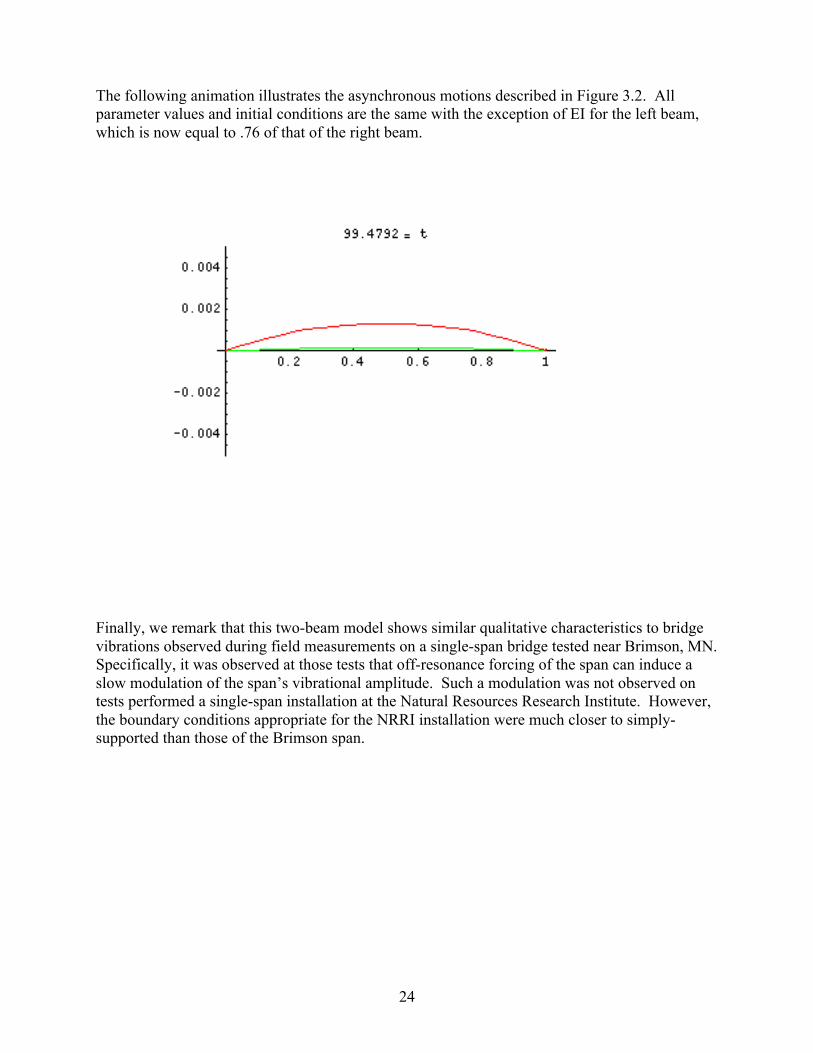
Moreover, with only a slight reduction of left beam EI to 76% of that of the right beam, the beams are seen to change to an out-of-phase motion, suggesting that reductions in span strength may induce torsional motions. These simulations also raise the question of whether such beam system can support simultaneous stable periodic solutions (one in phase, the other out of phase.)

23
The following two animations illustrate the two forms of motion. The first animation is based on the same parameters as Figure 3.2. It shows the synchronous nature of the beam motions. The EI value for the left (green) beam is equal to .78 of that of the right (red) beam. The right beam is forced, while the motion of the left beam is induced only by it connection to the right beam.
24
The following animation illustrates the asynchronous motions described in Figure 3.2. All parameter values and initial conditions are the same with the exception of EI for the left beam, which is now equal to .76 of that of the right beam. Finally, we remark that this two-beam model shows similar qualitative characteristics to bridge vibrations observed during field measurements on a single-span bridge tested near Brimson, MN. Specifically, it was observed at those tests that off-resonance forcing of the span can induce a slow modulation of the span’s vibrational amplitude. Such a modulation was not observed on tests performed a single-span installation at the Natural Resources Research Institute. However, the boundary conditions appropriate for the NRRI installation were much closer to simply- supported than those of the Brimson span.

25
While a thorough investigation of such systems was beyond the scope of this project, the techniques developed by this study provide the necessary mathematical tools.

26
Chapter 4: Point-Loaded Spans A serious difficulty in using (3.7) as a predictive model of span strength lies in the difficulty of estimating span mass. In some situations, researchers have been able to obtain such estimates by measuring span components and estimating component densities [39]. However, bridge spans often accumulate dirt and gravel on the span surface and supporting stringers. Such accumulations will affect observed span natural frequency, and therefore complicate the use of (3.7). Road engineers at the Institute of Public Works Engineering Australia (IPWEA), working in collaboration with the Center for Building Infrastructure Research (University of Technology Sydney), have recently proposed a two-step measurement method to address this situation. In their tests, they measure span oscillation frequencies induced by calibrated impact hammers. These frequencies are measured first for an unloaded span, then for the same span with an applied load. Applying a Bernoulli-beam model [18], the group claims that one can, with this additional data, eliminate the need for an independent measure of bridge mass [19,20]. Their testing procedures can be applied to vibrationally forced bridge tests, as well. A part of this investigation, we have performed a rigorous mathematical analysis of this type of testing method. Project partners at the Natural Resources Research Institute (University of Minnesota) and the US DA Forest Service have performed various trial tests, and provided us with useful data for model assessment. Model Derivation The full details of the point-loaded span system is to be found in [61]. We only give here a general overview of the results, and refer the reader to that reference for a complete descussion. The beam-based model under examination can be represented by (4.1) (ρA + Δmδ (x − x0 ))wtt = −EIwxxxx , δ (x) is the Dirac delta function, and Δm is the (point) mass loaded at position x0 on the span 0 < x0 < L . The displacement w is assumed to satisfy (2.6) and simply-supported boundary conditions (2.7) or clamped boundary conditions (2.11). In order to analyze the model, (4.1) is considered on the intervals 0 < x < x0 , x0 < x < L , and at x = x0 . At the point x = x0 one has (4.2) Δmwtt (x0 ,t) = −EI(wxxx (x0
− ,t) − wxxx (x0+ ,t))
in addition to the interior smoothness constraints (4.3) w(x0
− ,t) = w(x0+ ,t)
(4.4) wx (x0
− ,t) = wx (x0+ ,t)
(4.5) wxx (x0
− ,t) = wxx (x0+ ,t) .

27
The method of separation of variables applies to this linear system w(x,t) = T (t)ϕ(x) . For the interval 0 < x < x0 ϕ satisfies two boundary conditions at the point x = 0 , while on x0 < x < L it satisfies two boundary conditions at x = L . Equations (4.2)-(4.5) result in four additional conditions on ϕ . The resulting linear system can be shown to have nontrivial solutions for specific eigenvalues γ = γ n , which depend on system parameters, the point of loading, x0 , and the ratio of added load, Δm , to total span mass, ρA . The eigenvalues γ n satisfy an equation of the form a(γ L) + b(γ L, x0 L)(Δm ρA) = 0 , where a(γ L) = 0 is the special case associated with the unloaded span. That is, one has (4.6) γ nL = gn (x0 L ,Δm / ρA) for computable values gn (x0 L ,Δm ρA) . As in these special cases, the frequencies of the various modes of oscillation are directly expressible in terms of the eigenvalues, γ n . One arrives at the relation
(4.7) f 1 =gn2
2πEIρA
1L2
,
where f 1 denotes the fundamental frequency of the point-loaded model. See [61] for details. The analysis of this model is much more complicated that that encountered in [18] in that (for the sake of simplicity) they assume that the effect of bridge loading on span fundamental frequency can be modeled as if the point load was uniformly distributed across the bridge span, and that the span is simply supported. That is, they use (2.10) in the form
(4.8) f1 =π2
EIL(ρAL + Δm)
1L2
Both (4.7) and (4.8) provide possible means of estimating span EI in terms of (loaded) span frequency. Taken in conjunction with (2.10), one can use either to eliminate the need for the estimation of total bridge mass ρAL when deducing span EI from the observed fundamental frequency. In [61] an analysis is given of the error associated with using (4.8) rather than the more correct (4.7). The results therein allow for an analysis of the dependence of estimated span strength (EI ) on the size of the load, Δm , as well as the location of the load, x0 . A general conclusion of this study is that the Australian method of mathematically modeling loaded spans leads (fortunately) to a more conservative estimate of span strength. Vibrational Testing with Point Load The investigation was performed in conjunction with field tests of a number of single-span timber bridges. Tests were performed over the summers of 2005 and 2006 by researchers at the Natural Resources Research Institute (University of Minnesota) and the USDA Forest Service [39]. In particular, on July 12, 2005, bridge #619 in St Louis County, MN was measured

28
vibrationally both with and without a 1000 lb load placed center-span. This single-span bridge, is constructed of 13 stringers beams with a transverse plank surface. It has dimensions 17.9 feet (Length, L ) and 18.1 feet (width.) The observed resonance frequency for the unloaded span was 22.22 Hz, while the resonance frequency of the loaded span was measured at 26.46 Hz. The general theoretical framework described in [61] predicts that fundamental (bending) mode frequency should
decrease (rather than increase) with load. However, as described below, fundamental torsional frequency is predicted to increase. This suggests that the measured mode of vibration may have been of torsional type, rather than bending type. Bridge strength was also tested in the traditional (static load) manner, involving the measurement of span deflections due to the presence of a loaded gravel truck (33,680 lbs placed mid-span). Bridge strength is estimated to be 18,000 (EI 106 lb-in2) [40] and bridge weight is estimated to be 6,530 lb [39]. On July 13, 2005, bridge #726 in St. Louis County was similarly tested. This three-span bridge was constructed of 14 stringer beams covered by transverse running boards. Due to time constraints, only the middle and west spans were tested. The middle span was dead-load tested, as well as vibrationally tested both with and without a center load of 1000 lbs.
Dimensions of the middle span are 19.36 feet (length) and 24.35 feet (width.) Unloaded, the resonance frequency was observed to be 30.3 Hz, while under loading the resonance frequency was measured at 29.8 Hz. Thus in this test, bridge loading had a small affect on measured span resonance frequency. An estimate (using bridge component dimensions and an estimate of wood density) of span weight is 14,000 lb [39]. Thus, a 1000 lb load corresponds to

29
only a 7% increase of total span weight. The models of [61] (described below) predict only a 5% decrease in frequency, which is comparable to the 4% error in measuring span resonance frequency. Span EI is static-load-estimated at 37,000 (106 lb-in2). Interestingly, a support beam for the middle span was observed to be significantly decayed. This condition may be a reason that the (static-load) estimate of span strength was lower than expected [40], and may also contribute to the small measured effect of loading on span resonance frequency. West span dimensions were 18.45 feet (length) by 24.3 feet (width), with span weight 14,000 lb, unloaded resonance frequency of 32 Hz and static-load-estimatedEI of 55,000 (106 lb-in2). The resonance frequency of this span was not measured under load conditions.
In general, measured vibrational frequencies of single-span bridges have been observed to range from 17.5 Hz to 35.0 Hz. Bridge stiffnesses (EI as measured with static-load) ranged from 5,100 to 200,000 (106 lb-in2), and show a quadratic increase with measured fundamental frequency, as the models of this study substantiate [40]. An important question related to the interpretation of this data is whether the mode of measured vibrational motion is of simple bending type, or if it is torsional in
nature. The measured effect of load on resonance frequency has led to an analysis of a point-loaded beam with torsional capabilities. Torsional Motions The techniques developed above have been applied to beam models incorporating torsional motion. If one denotes by θ(x,t) the cross-sectional angular displacement of a beam at time t and location x 0 < x < L , then for a beam with a point mass, Δm , loaded at point x = x0 (0 < x0 < L ), θ satisfies a system of the type (4.9) (ρA + Δmδ (x − x0 ))θtt = GIθxx for 0 < t and 0 < x < L . Assuming that the sill plate prevents torsional motion at the span/sill-plate connections, θ must satisfy the boundary conditions (4.10) θ(0,t) = θ(L,t) = 0 . By analogy to the previous model, (4.9) is considered on the intervals 0 < x < x0 , x0 < x < L , and at x = x0 . At the point x = x0 one has (4.11) Δmθtt (x0 ,t) = GI(θx (x0
+ ,t) −θx (x0− ,t))

30
in addition to the interior continuity requirement (4.12) θ(x0
− ,t) = θ(x0+ ,t) .
See [43] for a discussion of the controllability of this system interpreted in the context of a point-loaded string. The method of separation of variable applies, and one finds that mode frequencies are of the form
(4.13) fn =hn2π
GIρA
1L
,
where (4.14) hn = hn (x0 L ,Δm / LρA) is a computable function of point load location x0 L and the ratio of the load mass Δm to the mass of the unloaded beam LρA . In the unloaded case, one computes the fundamental forcing
frequency to be f1 =12L
GIρA
. The more general relation (4.13) allows for a thorough
examination of the effects of point beam loading and the (fundamental) torsional frequency. See [61] for details.

31
Chapter 5: Conclusions and Recommendations This research has resulted in a number of direct and indirect benefits:
1. The development of more sophisticated modeling techniques than those used by previous researchers has resulted in computational methods for examining the reliability of using forced vibrational response data as a means of measuring the structural soundness of timber bridges. Using bridge architectural and material information obtained from project partners, the numerical evaluation of the established models has allowed the estimation of the relative error in predictions of bridge strength due to 1) misidentification of model boundary conditions, and 2) inaccurate estimates of bridge mass. The numerical algorithms developed herein can be applied to computational models of a wide class of stringer-based bridge spans, as illustrated in this report.
2. The development of models specifically designed to emulate the vibrational response of
mass-loaded single-span bridges is a first step in the development of a new regime of field tests for the estimation of bridge strength. The Institute of Public Works Engineering Australia estimates that a similar (hammer impact) method is only 15-20% the cost of static load testing. This modeling effort was needed to first examine the feasibility of the new test procedure. The results have resulted in a better understanding of the reliability of the IPWEA method. The conclusions of our study are that the mathematically simplistic treatment of a point load as if it were uniformly distributed across the span leads to an error in span strength (EI ) that increases with load size. However, the error is one that gives an underestimate of span strength, so is safe in nature. Furthermore, our work indicates that in order for such tests to be useful, bridge loads should be at least 25% of the (unloaded) span weight.
3. While concrete and steel structures are important state-wide, the wetlands characteristics
of northern Minnesota suggest that equal importance should be given to short-span installations (under 20 feet). A careful investigation carried out in the state of Ohio concludes that single span panel-laminated timber bridges offer significant economic benefits over steel/concrete bridges, concrete culvert, and corrugated metal arch pipe alternatives [23]. Specifically, factory-fabricated panel-laminated bridges are quick and easy to erect, not requiring the special technical expertise and heavy equipment associated with steel and concrete bridges. For northern climates, is it particularly important to note that timber spans are not as affected by corrosive road chemicals, nor are they subject to the winter maintenance costs associated with frozen culverts (which, additionally, are subject to significant winter-induced stresses.) Modern timber bridges have been shown to possess significantly longer life spans than for alternate installation types. As rising health costs impact regional transportation staffing decisions, the reduced installation and maintenance costs associated with timber installations may, in themselves, be a deciding factor in their selection. Reliable, cost-efficient vibrational inspection tests provide another advantage for their use.
4. The results of this investigation suggest that for existing bridge structures, future
experimental and theoretical work should focus on the development of vibrational

32
monitoring methods, rather than predictive strength formulae. While the bridge span strengths of existing structures has been shown to be correlated to vibrational frequency [40], the diversity of older span architectural designs, environmental influences, and non-span related modes of structural wear make the deduction of span strength from vibrational measurements problematic. However, for in-service structures, the periodic monitoring of a bridge's vibrational characteristics (examined in the context of a historic diary of previous sensor measurements) provides an important measure of bridge behavior. Observed changes in a bridge span's vibrational signature can be used as an indicator of possible structural issues, and can identify structures requiring further examination. In general, it may be that the most cost-efficient mean of monitoring existing timber spans is to perform (once) a simultaneous static-load test of bridge strength and a vibrational test of span resonance frequency. Such a test combination will result in an estimate of span mass. Subsequent (regularly or continually applied) tests monitoring span resonance frequency can then be used to predict static-load span deflections and span strength.
5. Numerical simulations performed as part of this investigation point out the potential
complexity of span vibrational characteristics, and demonstrate that mid-span vibrational profiles may often be more complicated than the simple "sinusoidal" profiles associated with simply-supported beams. In particular, the more-realistic nonlinear boundary conditions modeled in this work have resulted in observed periodic span motions with multiple maxima/minima within a typical vibrational cycle. This suggests that automated measurements of span resonance frequencies should not predicated on the assumption of simple vibrational profiles. However, our numerical experiments have demonstrated an easy and reliable measure of vibrational amplitude that does not require the knowledge of cycle profile maxima/minima.
6. While it is expected that the vibrational tests developed and tested initially for timber
bridge spans will also be useful to steel and concrete structures, it should be recognized that bridges supported with suspension cables have been demonstrated to posses highly complex vibrational characteristics. The work of [21, 48-51] suggests that in the case of suspension bridges, vertical vibrational forcing can lead to significant torsional motions due to the nonlinear nature of the cable support forces. Their work is also relevant to certain timber designs, as well. In particular, it is plausible that one might observe qualitatively similar motions in timber spans with stiff transverse spreader beams and heavy rail supports (design characteristics typical of current Wheeler-type panel-laminated bridges.) The numerical modeling work of this investigation does not include such design assumptions, although such model extensions are feasible.
7. A motivating problem for this investigation has been the issue of determining whether
field-measured span resonance frequencies are due to simple vertical (“bending”) nodes of vibration, or due to torsional motions. Our examination of the effects of bridge loading on measured resonance frequencies suggests that vertical and torsional resonance frequencies should respond differently to bridge loading, with bending frequency decreasing and torsional frequency increasing with load [61]. Further work in this area may provide a means of identifying span vibration type.

33
8. This project has provided important opportunities for student participation. Two graduate students in the UMD Program in Applied and Computational Mathematics were included in this phase of collaboration. Their work is documented in two Plan B Masters Projects described in UMD Mathematics Department Technical Reports [60,61], as well as in poster presentations [41,42]. Furthermore, the results obtained in this work have identified a number of related problems suitable for subsequent undergraduate and graduate student research, as well as classroom presentation.
Chapter 6: Recommended Problems for Further Study

34
Future work should focus on the modeling of single-span timber bridges of two specific (and common) classes: 1) stringer-based spans with transverse deck planking, and 2) dowel panel-laminated spans. For the first class, the beam-based models derived herein should be further modified so as to allow for a wider variety of multi-beam systems with transverse connection methods. In doing so, the derived functional dependencies relating bridge strength and vibrational characteristics can be extended to this more realistic class of bridge models, and important unresolved questions regarding torsional motions can be investigated via numerical simulation. Future work should continue towards generalizing the existing beam model with point loading to models incorporating nonlinear boundary conditions, also with the goal of including the effects of torsion. Further field and laboratory tests are necessary to help guide theoretical considerations. Most relevant to the issues studied here, it would be useful to have a larger class of tests in which static-load estimation of span strength is done simultaneous to vibrational test with and without load. Such tests should be performed at in-service spans, as well as span modules prior to installation. The results of this study indicate that measuring span frequency both with and without load will be useful information, but will require a load that is at least 25% of estimated span weight in order to clearly affect structure frequency. As recommended above, it may be that a cost-efficient mean of monitoring existing timber spans is to perform (once) a simultaneous static-load test of bridge strength and a vibrational test of span resonance frequency. When so done, it would be useful to measure structural resonance frequency when the span is subjected to the same load used in the static measurements of span EI. While aforementioned studies have focused on bridges constructed with longitudinal stringers covered with transverse planking, more modern wooden structures and new installations are primarily of panel-laminated type. See [31] for a description of the most common architectural designs. There are a number of important factors that suggest that pre-fabricated timber bridges possess important advantages over concrete/steel bridges when considering the type of structure to be used in new or replacement installations [23]. While there has been some success in applying finite element (FE) computational models in the analysis laminated panel bridge spans [35], there has been no previous work in the development of continuous mathematical models of such structures for the purpose of monitoring their strength characteristics. Independent personal communications with both USDA Forest Service staff (James Wacker and Xiping Wang) and Kenneth Johnson, PE, Wheeler Consolidate, Inc. (a regional supplier of treated timber bridges) suggest the need to consider plate-based models of timber bridge response to forced vibrations. He indicates that the vast majority of new timber installations are of dowel panel-laminated type. As a first step, one should consider the construction of plate-based models for the second class of span architectures, and begin a modal analysis of the resulting equations. For panel-laminated spans, Kirchhoff plate models [25-27] are more appropriate than the Bernoulli beam models considered for stringer-based bridge spans. Finite element modeling techniques have been used for the simulation of full-scale structures [5] and, in particular, have been used recently used in connection with (dowel) panel laminated spans of the type currently manufactured by Wheeler Lumber, LLC [35]. Wheeler engineer Kenneth A. Johnson, PE has indicated an interest in sharing with investigators the MATLAB computer code developed in [35]. If obtained, it would provide a means of calibrating (Kirchhoff) plate-based models of panel laminated single-span

35
bridges, as well as the potential of creating a MATLAB code for the simulation of forced panel-laminated spans, or for computing modes of oscillation for the FE model of [35]. Model validation can also be done using published information from the [35], while model parameter identification can also make use of data provided by Brashaw, Ross and Johnson [30]. Fundamental questions regarding bridge skew remain unstudied, but are now accessible. Wheeler engineer Johnson indicates that almost 90% of timber installations involve a skewed architecture. The effects of bridge skew on the vibrational characteristics of bridge spans remains as an important issue for future investigations.

36
Acknowledgments: The participants of this project gratefully acknowledge the support and encouragement of a number of individuals. In particular, this project would not have been possible without copious input from Brain Brashaw and Robert Vatalaro (Natural Resources Research Institute, Duluth, MN), and Robert Ross, James Wacker and Xiping Wang, (USDA Forest Service, Madison, WI). We also acknowledge the encouragement of the Dr. James Riehl and Carol Wolosz (Northland Advanced Transportation Systems Research Laboratories, University of Minnesota Duluth, Duluth, MN.) References: [1] FHWA. 2002. National Bridge Inventory Program. www.fhwa.dot.gov/bridge/nbi.htm. Washington, DC: Federal Highway Administration. [2] Phares. B.M.; Rolander, D.D.; Graybeal, B.A.; Washer, G.A. 2000. Studying the reliability of bridge inspection. Public Roads, Vol. 64, No. 3. Washington, DC: Federal Highway Administration. [3] Phares. B.M.; Rolander, D.D.; Graybeal, B.A.; Washer, G.A. 2001. Reliability of visual bridge inspection. Public Roads, Vol. 64, No. 5. Washington, DC: Federal Highway Administration. [4] Ross, R.J.; Pellerin, R.F.; Volny, N.; Salsig, W.W.; Falk, R.H. 1999. Inspection of timber bridges using stress wave timing nondestructive evaluation tools, Tech Rep. FPL-GTR-114, Madison, WI [5] Emerson, R.N.; Pollock, D.G.; Kainz, J.A.; Fridley,K.J.; Melean, D.; Ross, R.J., Nondestructive evalution techniques for timber bridges, NDT.net, Vol. 4, No. 11, November 1999 [6] Peterson, S. T., McLean, D. I., Symans, M. D., Pollock, D. G., Cofer, W. F., Emerson, R. N., and Fridley, K. J. 2001a. Application of dynamic system identification to timber beams: I. ASCE Journal of Structural Engineering, 127(4), 418–425. [7] Horyna, T.; Foschi, R.O.; Ventura, C.E. 2001, Response of timber bridge to traffic loading. ASCE Journal of Bridge Engineering, 6(1), 69-77 [8] Wang, X.P.; Ross, R.J.; Erickson, J.R.; Forsman, J.W., Low frequency vibration approach to assess the performance of wood structural systems, Project No. 187-6482, NRRI/TR-2003/36, October 2003 [9] Morison, A., Nondestructive Evaluation of Short Span Timber Bridges with Impact Generated FRFs. Masters Thesis. Michigan Technological University, 2003. [10] B. Brashaw and R. J. Ross, personal communication.

37
[11] S. Rao, Mechanical Vibrations, 2nd Ed. Addison-Wesley, 1990.
[12] M. Roseau. Vibrations in Mechanical Systems. Springer-Verlag, Berlin, West Germany, 1984 [13] Thomson. Theory of Vibrations with Applications. Prentice-Hall, Upper Saddle River, New Jersey, fourth edition, 1993. [14] B. Tongue. Principles of Vibration. Oxford University Press, New York, 1996. [15] Geist, B.; Mclaughlin, J.R., Eigenvalue formulas for the uniform Timoshenko beam: The free-free problem, Electronic Research Announcements of A.M.S., Vol. 4, 12-17, 1998 [16] Geist, B.; Mclaughlin, J.R., Asymptotic formulas for the eigenvalues of the Timoshenko beam [17] Krauthammer, T.; Schoedel, R.; Shanaa, H., Nonlinear analysis of reinforced concrete structural elements according to the Timoshenko beam theory, Final report, prepared for U.S. Army etc., 2002 [18] Blevins, R.D., Formulas for Natural Frequency and Mode Shape, Krieger Publishing Company, Malabar, Florida, 1993. [19] Champion, C.; Samali, B.; Li, J.; Crews, K.; Bakoss, S., Assessing the load carrying capacity of timber bridges using dynamic methods, IPWEA Queensland Division Annual Conference 2002. [20] Crews, K.; Champion, C., Assessing load capacity of timber bridges, http://www.lgaq.asn.au/4A256A9A0014D12D/resources/Conf-Roads03/$FILE/crews_champion.pdf [21] Humphrey, L.D. and McKenna, P. J., Using a Gradient Vector to find Multiple Periodic Oscillations in Suspension Bridge Models, 16-26, The College Mathematics Journal, Vol 3., No. 1, Jan, 2005. [22] Fei, G; Liu, Z; Stech, H; Trogdon, S; Erickson, J. and Wang, F.; Bridge Strength Predicting by Natural Frequency of Vibration, Poster Presentation, NATSRL Research Day, November, 4, 2004. [23] Kainz, J and Hill, C; McCurdy Road Stress-Laminated Timber Bridge; A Viable Option for Short-Span Design, in Ritter, et al, ed(s), National Conference on Wood Transportation Structures, Oct, 1996, USDA Forest Service, Forest Product Laboratory. [24] Wang, X,; Wacker, J; Ross, R; and Brashaw, B., Nondestructive Assessment of Timber Bridges Using a Vibration-Based Method, ASCE preprint, December, 2004. [25] Gorman, D., Vibration Analysis of Plates by the Superposition Method, World Scientific Pub. Co,. 1999.

38
[26] Morely, L., Skew Plates and Structures, Pergamon Presss, 1963. [27] Ling, F. F. (ed), Vibrations of Elastic Plates, Springer-Verlag, New York, 1995. [28] Nowak, A and Ritter, M., Load and Resistance Factor Design Code for Wooden Bridges, in Procedings of 4th Int’l Bridge Engineering Conf, August, 1995, National Academy Press, 351-357, 1995, Vol. 2. [29] Thomas, R. and Puckett, J.; Analysis , Design, Rating, and Drafting of Wood Bridge Superstructures, in Ritter, et al , ed(s), National Conference on Wood Transportation Structures, Oct, 1996, USDA Forest Service, Forest Product Laboratory. [30] Johnson, K., Design of Treated Timber Bridges, Technical Report, Wheeler Consolidated, Inc., March, 2002. [31] Johnson, K., Timber Bridge Decks, Technical Report, Wheeler Consolidated, Inc., April, 2002. [32] Ross, R., Brashaw. B.; Wang, X.; White, R.; and Pellerin, R.; Wood and Timber Condition Assessment Manual, Forest Products Society, 2004. [33] Pellerin, R., and Ross, R.; Nondestructive Evaluation of Wood, Forest Products Society, 2004. [35] Stolarski, H, et al; The Effects of Transverse Stiffener Beams on Shear Transfer, Technical Report MN/RC – 2003-12, Minnesota Department of Transportation, January, 2003. [36] Morison, A.; el al; Timber Bridge Evaluation: A Global Nondestructive Approach Using Impact Generated FRFs, in Proceedings of the 20th International Modal Analysis Conference, 1567-1573, J. W. Forsman, ed, 2002. [37] Groenier, J. S., Load Rating of Single Span, Glulam Beam Bridges using Two Computer Applications, in Ritter, et al , ed(s), National Conference on Wood Transportation Structures, Oct, 1996, USDA Forest Service, Forest Product Laboratory. [38] Boyce, W. E. and R. C. DiPrima, Elementary Differential Equations and Boundary Value Problems, John Wiley & Sons, 1977. [39] B. Brashaw and R. Vatalaro, personal communication. [40] Brashaw, B., R. Vatalaro, X. Wang, J. Wacker, R. Ross, Poster Presentation: NATSRL Research Day, “Development of Flexural Vibration techniques to Rapidly Assess the Structural Health of Rural Bridge Systems,” [41] Erickson J., Liu, Z., Trogdon, S., H. Stech and F. Wang, Poster Presentation: NATSRL Research Day, A Numerical Study of the Impact of Boundary Conditions on the Free Vibrations of Beams, November 3, 2005.

39
[42] Wang F., Liu, Z., Trogdon, S., H. Stech and J. Erickson, Poster Presentation: NATSRL Research Day, A Point Load Model of the Vibrational Testing of Timber Bridges, November 3, 2005. [43] Hansen, S. and E. Zuazua, Exact Controllability and Stabilization of a Vibrating String with Interior Point Mass, SIAM Journal of Control and Optimization, Vol. 33, No. 3, 1357-1391, 1995. [44] Johnson, K., Repair and Rehabilitation of Treated Timber Bridges, Technical Report, Wheeler Consolidated, Inc., April, 2002. [45] Crews, K., Samali, B., Li, J., Bakoss, S., Champion, C., Testing and Assessment Procedures to facilitate the Management of Timber Bride Assets, IPWEA Queensland Division http://www.ipwea.org.au/upload/TBD%20bridge%20paper%20v4.pdf. [46] Glover, J., Lazer A., and McKenna, P. J., Existence and stability of large scale nonlinear oscillations in suspension bridges, The Journal of Applied Mathematics and Physics (ZAMP), Vol. 40, 172-200, March, 1989. [47] Choi, Y., Jen K., and McKenna, P. J., The Structure of the Solution Set for Periodic Oscillations in a Suspension Bridge Model, IMA Journal of Applied Mathematics, Vol. 47, 283-306, 1991. [48] McKenna, P. J. and K. S. Moore, Multiple periodic solutions to a suspension bridge ordinary differential equation, Nonlinear Differential Equations, Vol. 05, 183-199, 2000. [49] Lazer A. C., and McKenna, P. J., Large-scale oscillatory behavior in loaded asymmetric systems, Ann. Inst. Henri Poincare, Vol. 4, No. 3, 243-274, 1987. [50] McKenna, P. J. and C. Tuama, Large Torsional Oscillations in Suspension Bridges Visited Again: Vertical Forcing Creates Torsional Response, Mathematical Association of America Monthly, Vol. 108, 738-745, 2001. [51] McKenna, P. J., Large Torsional Oscillations in Suspension Bridges Revisited: Fixing and Old Approximation, The College Mathematics Journal, 1-18, January, 1999. [52] Ritter, M. A., R. C. Moody, and S. R. Duwadi, Summary of U.S. Research on Wood Transportation Structures, in V. Gopu, ed. Proceedings of the International Wood Engineering Conference ‘96, 81-88, October, 1996. [53] Wipf, T., M. Ritter, and D. Wood, Dynamic Evaluation of Timber Bridges, in Ritter, et al, ed., National Conference on Wood Transportation Structures ‘96, 81-88, October, 1996. [54] Wipf, T., M. Ritter, and D. Wood, Dynamic Evaluation and Testing of Timber Highway Bridges, in Wlford, G. B. and D. J. Gaunt ed., Pacific Timber Engineering Conference 1999, Vol. 3, 333-339, 1999.

40
[55] Wipf, T., M. Ritter, and D. Wood, Dynamic Evaluation of Wood Bridges, in Sanayei, M. ed., Restructuring America and Beyond: Proceedings of Structures Congress 13, 1995, Vol. 1, 1-4, 1995. [56] Wipf, T., M. Ritter, and D. Wood, Dynamic Evaluation of Glued Laminated Timber Bridges, in Sanayei, M. ed., Restructuring America and Beyond: Proceedings of Structures Congress 13, 1995, 260-267, 1995. [57] Ritter, M. A., D. L. Wood, and T. J. Wipf, C. Wijesooriya, and S. R. Duwadi, Dynamic Response of Stress-Laminated-Deck Bridges, in Proceedings of the 4th International Bridge Engineering Conference 1995, Vol. 2, 381-394, 1995. [58] Kainz, J. A., Field Performance of Timber Bridges, USDA Forest Service, Forest Product Laboratory, Research Paper FPL-RP-570, 1998. [59] Kainz, J. A., J. Wacker, and M. Ritter, Analysis of Thermal Change in Stress-Laminated Timber Bridge Decks, USDA Forest Service, Forest Product Laboratory, Research Paper FPL-RP-598, 2001. [60] Erickson, J., The Impact of Boundary Conditions on the Free Vibrations of Beams, Technical Report 2006-3, Department of Mathematics and Statistics, University of Minnesota, January, 2006. [61] Wang, F., Testing Wood Bridges with Non-Destructive Methods, Technical Report 2006-4, Department of Mathematics and Statistics, University of Minnesota, August, 2006.