modeling and testing of electric vehicle propulsion systems · modeling and testing of electric...
TRANSCRIPT

U.P.B. Sci. Bull., Series C, Vol. 77, Iss. 3, 2015 ISSN 2286-3540
MODELING AND TESTING OF ELECTRIC VEHICLE PROPULSION SYSTEMS
Adrian BĂLŢĂŢANU1, Marin-Leonard FLOREA2
A modeling with MATLAB environment using two toolboxes, Simulink and ADVISOR, of an electrical machine and a hybrid propulsion system, is presented in this paper. A mathematical model of the permanent magnet synchronous machine is implemented, other than the initial model used by MATLAB, and also remodeled the entire electric drive scheme for testing the parameters. The build of the electric propulsion system of the hybrid vehicle was made with blocks and tutorials offered by Simulink and ADVISOR toolboxes. These toolboxes are very useful for studying and development of new structures of electrical and mechanical models for automobiles or other devices.
Keywords: electric vehicles, propulsion systems, electric motors
1. Introduction
Electric vehicle as an object of study is rich in open problems both technical and socio - economic. At present, interest in electric vehicles road reached a very high level. Undoubtedly, these vehicles will be part of the main means of transport of the future but for them to dominate the market of road vehicles, there is still much research efforts dedicated to this purpose. Also, new industries will be created and will have trained many professionals in the fields of electric propulsion systems and components of these systems. Rotary motors are the main components of electric propulsion systems of road vehicles (scooters, cars, buses) [1].
There are several types of electric motors can be used in vehicle propulsion systems: DC motors, synchronous motors with permanent magnets or electromagnetic excitation, switched reluctance synchronous motors, squirrel cage induction motors. Performance of these engines, with performance electric batteries or other energy storage mobile units, largely conditions techno - economic performance of electric vehicles, which require careful consideration of their choice.
1 Eng., Dept. of Machines, Materials and Electrical Drives, University POLITEHNICA of
Bucharest, Romania, e-mail: [email protected] 2 Eng., Dept. of Machines, Materials and Electrical Drives, University POLITEHNICA of
Bucharest, Romania, e-mail: [email protected]
202 Adrian Bălţăţanu, Marin-Leonard Florea
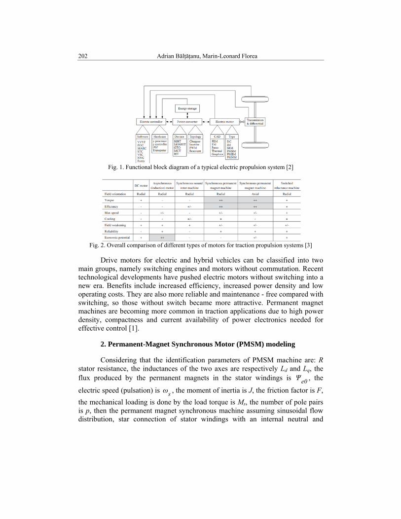
Fig. 1. Functional block diagram of a typical electric propulsion system [2]
Fig. 2. Overall comparison of different types of motors for traction propulsion systems [3]
Drive motors for electric and hybrid vehicles can be classified into two
main groups, namely switching engines and motors without commutation. Recent technological developments have pushed electric motors without switching into a new era. Benefits include increased efficiency, increased power density and low operating costs. They are also more reliable and maintenance - free compared with switching, so those without switch became more attractive. Permanent magnet machines are becoming more common in traction applications due to high power density, compactness and current availability of power electronics needed for effective control [1].
2. Permanent-Magnet Synchronous Motor (PMSM) modeling
Considering that the identification parameters of PMSM machine are: R stator resistance, the inductances of the two axes are respectively Ld and Lq, the flux produced by the permanent magnets in the stator windings is e0Ψ , the
electric speed (pulsation) is sω , the moment of inertia is J, the friction factor is F, the mechanical loading is done by the load torque is Ms, the number of pole pairs is p, then the permanent magnet synchronous machine assuming sinusoidal flow distribution, star connection of stator windings with an internal neutral and

Modeling and testing of electric vehicle propulsion systems 203
regarded as studied in referential d,q rotor accepts the following system of equations:
( )( )
[ ]( ) s
sselmg
dqqdelmg
qqq
e0ddd
dsqqq
qsddd
Mpω
Fωdtd
pJT
iΨiΨ2
3pT
iLΨ
ΨiLΨ
ΨωΨdtdiRu
ΨωΨdtdiRu
+⋅+⋅=
⋅−⋅=
⋅=
+⋅=
⋅++⋅=
⋅−+⋅=
(2.1)
System integro-differential equations of order 3 of the relations (2.1) are
chosen as state variables, fluxes qd Ψ,Ψ and speed sω , choices that comply
canonical integro-differential systems. Note:
dd L
Rω,LRω == (2.2)
Simple transformations we obtain the following results:
( )( )( ) [ ]( )
qqq
e0ddd
ms
dqqds
dsqqqq
qsdde0ddd
iLΨ
ΨiLΨ
Tpω
FiΨiΨ2
3pJpω
dtd
ΨωΨωuΨdtd
ΨωΨωΨωuΨdtd
⋅=
+⋅=
⎥⎦
⎤⎢⎣
⎡−−⋅−⋅=
⋅−⋅−=
⋅+⋅−⋅+=
(2.3)
Fig. 3 illustrates a MATLAB – Simulink model for PMSM machine built on relationships (2.3) [4], [5], [9].

204 Adrian Bălţăţanu, Marin-Leonard Florea
Fig. 3. MATLAB-SIMULINK model for simulation PMSM First column (left to right) of Fig. 3, contains two blocks (seen from
above) which makes the transition from the system balanced three-phase synchronous d,q,0. The symmetry of the three-phase system R,S,T justify retaining only the d and q components. In the second column of the second row of blocks are modeled evolution equations fluxes qd Ψ,Ψ , with the input voltages in
dq axes calculated in the one column blocks. The third column contains one line block calculation functions ( ) ( )tωcos,tωsin ss , necessary transformations of axes d,q,0 in axes R,S,T, this is done in the last column and first line. Block flow calculation results are used to block the second line third column to calculate the current axes d,q. Currents and flows axes d,q are directed to block the fourth line that blends mechanical equation of system (2.3). Fourth block column of the second line is used to obtain velocity rω and integral, which generates angle rotor
axis to a fixed referential previously selected, dtωθt
0rr ∫= .

Modeling and testing of electric vehicle propulsion systems 205
Fig. 4. Blocks used for fluxes calculation
Fig. 5. The icon of the permanent magnet synchronous machine
3. Test Permanent Magnet Synchronous Machine model The Fig. 5 is now used to obtain the results electromechanical. Voltage of
the PMSM have been obtained using the algorithm id = 0, by considering the relations (2.1) stationary regimes.
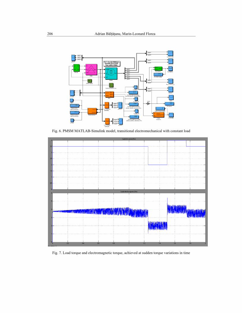
In the Fig. 7, PMSM model simulation results are rendered, for transitional electromechanical machine, at startup, if the mechanical load is constant and the rotor speed required is described by a function with the landing ramp. The ramp is applied to the range [0,1)t∈ , and landing is active on the range [1,2]t∈ .
.
206 Adrian Bălţăţanu, Marin-Leonard Florea
Fig. 6. PMSM MATLAB-Simulink model, transitional electromechanical with constant load
Fig. 7. Load torque and electromagnetic torque, achieved at sudden torque variations in time

Modeling and testing of electric vehicle propulsion systems 207
4. Simulation of Electric Vehicles MATLAB-Simulink modeling In the application is presented the construction, operation and system
methodology hybrid (HEV) series-parallel on the market in the Toyota Prius (Fig. 9). The application developed using Matlab toolbox's, SimPower and SimDriveline [10], presents hybrid system consisting of electric motor and internal combustion heat engine (ICE) in order to increase efficiency and reduce pollution traction. The hybrid system combines the advantages of the electric motor (no pollution and high power at low speeds) with the advantages of the internal combustion engine (reduced pollution at high speeds). Traction is performed using the combustion engine and two machines AC synchronous permanent magnet (brushless), one works as a motor and the other as a generator. The electrical system includes a DC / DC converter that is designed to convert voltage from 202 volts battery in the supply voltage of 500V AC motor. The train engine contains a planetary gear ring and a differential which divides torque evenly to the wheels. The two motors are synchronized by a management concept to ensure the greatest possible efficiency depending on the acceleration of the vehicle and road conditions. A dynamic longitudinal model of the vehicle is used to represent the movement and influence of various parameters on the entire system [11], [12]. Figure 8 shows positioning of the components in Toyota Prius hybrid system.
Fig. 8. Positioning of the components in the Toyota Prius hybrid system [7]

208 Adrian Bălţăţanu, Marin-Leonard Florea
Fig. 9. The hybrid system Toyota Prius - Simulink model
The simulation includes all cycles of a hybrid vehicle starting,
acceleration, recharging the battery while driving, energy regeneration during braking. The acceleration was achieved by depressing the accelerator pedal held steady at 70% for the first 4 seconds, the next 4 seconds not accelerating, then at 85% for 5 seconds and then holding back until the end of the simulation. As long as the required power for the machine is less than 15 kW, and the speed is less than 20 km / h, at displacement is using battery-powered electric motor (Fig. 10, 11).
Fig. 10. Simulation results: acceleration, speed, electrical power (motor, generator, battery),
variations in time

Modeling and testing of electric vehicle propulsion systems 209
Fig. 11. The simulation results of energy management system in time
MATLAB-ADVISOR modeling One of the most used software tools for the analysis of hybrid vehicles is
Matlab-Simulink simulation environment, plus package ADVISOR (Advanced Vehicle Simulator) [13], synthesized by the National Renewable Energy Laboratory in the U.S.A. It allows simulation of various structures and components of vehicles is useful for estimating energy consumption, exhaust emissions and evaluating energy management strategies for both conventional vehicles and especially for electric vehicles and hybrid electric vehicles (type series parallel or mixed). It works interactively with Matlab-Simulink programming environment and contains a database where there are important types of vehicles, thermal and electric motors, batteries, ultracapacitors, mechanical transmissions etc.

210 Adrian Bălţăţanu, Marin-Leonard Florea
Fig. 12. The hybrid system Toyota Prius – ADVISOR model
Fig. 13. Hybrid vehicle configuration parameters
wheel and axle front/rear <wh>
vehicle <veh>
gal
total fuel used (gal)
prius powerbus <pb>
prius gen/controller <gc>
planetary gearset
<pg> prius
motor/controller <mc> prius
fuelconverter
<fc> prius
final drive <fd>
exhaust sys<ex>
energystorage <ess>
drive cycle<cyc>
-C-
-C-
Version &Copyright
AND
Interactive Graphicsof f
emis
HC, CO,NOx, PM (g/s)
time
Goto<sdo>
fc_spd
Goto <svc>
Clock<vc> prius<sdo> prius
ex_cat_tmp
<cs>
2 axle -->1 drivelineconverter

Modeling and testing of electric vehicle propulsion systems 211
Fig. 14. Simulation results: speed, battery charge level, emission of pollutants, loss of braking
power, fuel consumption
Fig. 15. 3D representation - hybrid vehicle consumption: by weight and drag coefficient
Simulations, Toyota Prius hybrid vehicle, tests were made for European
road EUDC cycle on the distance of approximately 7km for 400s, maximum speed 120km/h. The vehicle uses the electric motor synchronous motor of 31kW, 43kW heat engine, and as energy storage devices, NiMH batteries (max power 40kW, nominal voltage 306V). The initial SOC is 70% for batteries. On the way, it took only one stop, average speed reached 63km/h. The results of fuel consumption and emissions, can be observed in Fig. 14, right side, acceleration tests also.
0.30.35
0.40.45
0.5
13001400
15001600
17001800
4
4.5
5
5.5
6
veh_CD
Litersp100km
veh_mass

212 Adrian Bălţăţanu, Marin-Leonard Florea
5. Conclusions In this paper, we present the modeling of an vehicle propulsion system,
hybrid vehicle, using the Matlab-Simulink simulation environment, plus package ADVISOR. First we had started with the mathematical model of the permanent magnet synchronous machine, used in electric propulsion of the hybrid vehicles. The results of the simulations show the behavior of parameters, under constant load and at sudden variations, the values can be used for better observation and optimization of electric drives with this type of machine. With the help of Simulink library we constructed a full hybrid vehicle model, the parameters are the same with the Toyota Prius vehicle, the results obtained can be compared with the model used in real life.
With the toolbox ADVISOR, used for the same hybrid architecture, we managed to obtain the results of speed, acceleration, state of charge (SOC), fuel consumption and polluting emissions, running an European driving cycle profile.
The results were satisfactory, but they can be improved by applying different control strategies for energy management, intelligent algorithms (genetic, PSO), or using multiple energy storage devices.
R E F E R E N C E S
[1] A. Bălţăţanu, L.M. Florea - Comparison of electric motors used for electric vehicles
propulsion, AFASES 2013, Braşov, 23-25 May 2013, pag. 367-372, ISSN 2247-3173. [2] Mehrdad Ehsani, Yimin Gao, Ali Emadi - Modern Electric, Hybrid Electric and Fuel Cell
Vehicles, Fundamentals, Theory and Design. Second Edition. CRC Press 2010. [3] Jonas Ottosson - Energy Management and Control of Electrical Drives. Lund University 2007. [4] Dragoş Kisch - Reglarea vectorială a maşinilor de curent alternativ (Vector control of AC
machines) , Editura ICPE, Bucureşti, 1977, ISBN 973-97863-6-7. [5] G.D.Andreescu - Robust direct torque vector control system with stator flux observer for PM -
SM drives, Record of OPTIM - 1996, Braşov, Romania, vol.5. [6] R.Krishnan - Electric Motor Drives, Modeling, Analysis, and Control, Prentice Hall, Inc., New
York 2001. [7] Dobri Cundev, Goce Stefanov, Vasilija Sarac - CONFIGURATIONS OF HYBRID-
ELECTRIC CARS PROPULSION SYSTEMS, Faculty of Electrical Engineering, University “Goce Delcev”.
[8] Alexandru Onea - Strategii de Control pentru Autovehicule Electrice Hibride (Control Strategies for Hybrid Electric Vehicles), PhD Thesis, Iaşi, 2012.
[9] Dragoş Kisch - Sisteme de reglare automată a maşinilor de curent alternativ (Systems for automatic regulation of AC machines), Editura ICPE, Bucureşti, Romania, ISBN 973-98322-6-1, 1998.
[10] *** http://www.mathworks.com/products/?s_tid=gn_ps [11] *** http://en.wikipedia.org/wiki/Hybrid_electric_vehicle [12] *** http://en.wikipedia.org/wiki/Toyota_Prius [13] *** http://bigladdersoftware.com/advisor/