modeling and simulation of pneumatic brake system used in ...the brake chamber is the one which...
TRANSCRIPT

IOSR Journal of Mechanical and Civil Engineering (IOSR-JMCE)
e-ISSN: 2278-1684,p-ISSN: 2320-334X, Volume 11, Issue 1 Ver. II (Jan. 2014), PP 01-09
www.iosrjournals.org
www.iosrjournals.org 1 | Page
Modeling and simulation of pneumatic brake system used in
heavy commercial vehicle
S.Mithun*, S.Mariappa
* Suresh Gayakwad
**
*Dep't of Automobile Engineering, Madras Institute of Technology, Anna University, Chennai, India
**WABCO India Ltd, Chennai, India
Abstract: An air brake system is used in heavy commercial vehicles for the purpose to stop or slow down the vehicle. The
effective braking depends mainly on the response time of the entire system. The brake system layout configuration has to be
designed in such a way that the response time should meet the vehicle safety standard regulations. This paper describes the
detailed modeling of the individual brake system products, right from the actuating valves, control valves, actuators and
foundation brakes. Response time prediction for a typical 4X2 Heavy commercial vehicle has been done. Also a study on
comparing the transient torque generated by the existing drum brake and an equivalent disc brake model was carried out.
The layout was modeled in one of the commercially available multi-domain physical modeling software employing bond
graph technique and lumped system.
Keywords : Response time, AMESim, Multi domain, Foundation brakes, Braking torque
I. INTRODUCTION The effective braking depends mainly on the response time of the entire system and driver's feel. The
response time is determined as the time elapsing between the beginning of the actuation of the control pedal and
the moment the pressure in the actuator reaches 75 percent of its asymptotic value[1]. The brake system layout
configuration has to be designed in such a way that the response time should meet the vehicle safety standard
regulations. The heavy commercial vehicle brake system layout is designed keeping various vehicle parameters
like Gross Vehicle Weight, wheel base, Centre of Gravity of the vehicle, number of axles etc. The system
layout design is extremely complex since it involves number of valves which have to function in a logical
sequence during different stages of braking (Normal, emergency, and One circuit failed
condition).Conventionally, the system layout design is arrived after many iterations based on field trials and
experience. This method involves more lead time and cost till the layout is finalized. Hence the modeling and
analysis of the system layout using AMESim helps us to predict the behavior of the layout in terms of response
and the effect of the individual subsystems, valves on the system behavior and thereby optimization study can
be carried out. This tool employs bond graph technique and lumped system for developing physical based
modeling. Sridhar [2] Describes the modeling of foot brake valve and predicting the dynamic response of the
individual valve.Wu [3] studied the robust of pneumatic brake system in commercial vehicle using AMESim.
[4], [5],[6] describes the modeling of system by simplifying the valves and the actuators. This paper describes
the detailed modeling of individual valves , and actuators by including all the design parameters, thereby makes
the model flexible to study the role of each and every design parameter on system level response. Apart from
this the paper deals the modeling of foundation brakes and compare the transient torque response of a typical
drum and equivalent disc brake for a heavy commercial vehicle. This model can be directly coupled to the
vehicle models and the dynamics of the vehicle like stopping distance, stability can be studied. This model can
also be used for design and optimization of brake system layouts for various heavy commercial trucks having
varying wheel base and Gross Vehicle Weight.
II. AIR BRAKE SYSTEM A typical Air brake system layout is show in Fig.1, which mainly consist of Compressor (Energy
source) Foot/Hand brake valves (Actuating unit) Relay valves (Control unit) and Actuators.
Figure 1 - Typical Air brake System layout.

Modeling and simulation of pneumatic brake system used in heavy commercial vehicle
www.iosrjournals.org 2 | Page
The compressor provides the compressed air, which is the energy source of air brake system. The Air dryer in
the layout absorbs the moisture in the pressurized air and also maintains the system pressure. The moisture free
compressed air will be stored in the reservoirs through the system protection valve. During normal brake
application, when the driver presses the pedal, the dual brake having two deliveries get actuated [1]. The
primary delivery gives signal to the relay valve which actuates the spring break actuator where the pressure is
converted into braking force. The braking force is transmitted to the foundation brakes through the slack
adjuster where it is converted into braking torque and applies brake on the rear wheels. The secondary delivery
of the valve actuates the brake chamber thereby applies the brake in the front wheels. In case of emergency
situations, the driver actuates the hand valve which applies the brake through the spring brake actuator.
III. MODELING AND SIMULATION The Air Brake System is modeled using, a commercial tool which has standard libraries for pneumatic,
mechanical components. The individual valves, actuators and foundation brakes were modeled using the
appropriate elements available in the libraries
1. Dual Brake Valve
Dual brake valve shown in Fig.2 provides graduated air pressure for applying and releasing of brakes
on application of driver's effort on the brake pedal. The dual brake valve have two independent deliveries, which
controls the primary(for rear brakes) and secondary (for front brakes) circuit of the brake system[2]. The
design of dual brake valve is such that it ensures uninterrupted supply of air pressure to secondary circuit even
in case of primary circuit failure and vice versa.
Based on its geometry and construction the product will be modeled using appropriate mechanical and
pneumatic components like piston, spring, and mass available in the library [6].
Figure 2 -Dual Brake valve
The flow passages, annular restrictions were modeled as orifices and were introduced in the corresponding
location. The mass flow rate of the orifice is governed by equation (1) [7].
1....
up
up
mqT
PCCAm
where
Pup - upstream pressure,
Tup - Upstream temperature,
Cm - Mass flow parameter,
Cq - Discharge coefficient
A -Area of cross section of orifice
The flow coefficient Cq is introduced to adjust the theoretical relation to experiments. This coefficient is less
than one and is used to include extra losses due to local friction and loss of kinetic energy. In all our cases it is
assumed as 0.7.
The valves having arrangement as shown in Fig.3 having dynamic flow area is modeled as pneumatic poppet
valves, which can accommodate the change in area during valve opening and closing.
Modeling and simulation of pneumatic brake system used in heavy commercial vehicle
www.iosrjournals.org 3 | Page
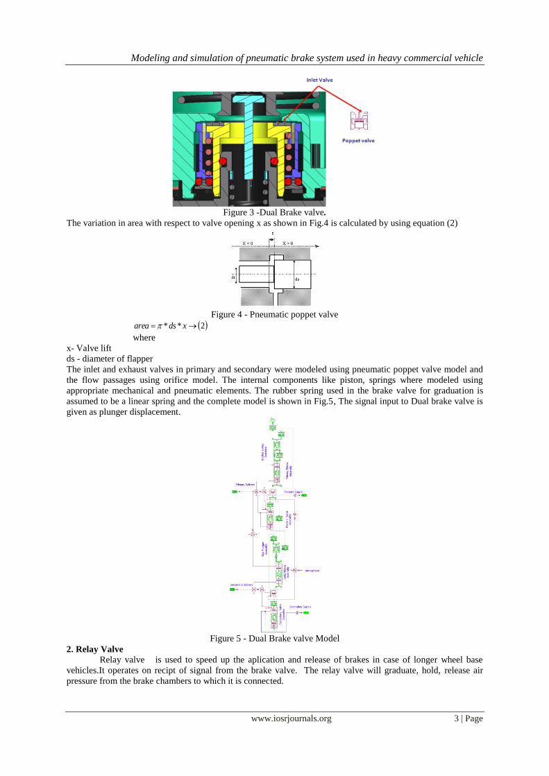
Figure 3 -Dual Brake valve.
The variation in area with respect to valve opening x as shown in Fig.4 is calculated by using equation (2)
Figure 4 - Pneumatic poppet valve
2** xdsarea
where
x- Valve lift
ds - diameter of flapper
The inlet and exhaust valves in primary and secondary were modeled using pneumatic poppet valve model and
the flow passages using orifice model. The internal components like piston, springs where modeled using
appropriate mechanical and pneumatic elements. The rubber spring used in the brake valve for graduation is
assumed to be a linear spring and the complete model is shown in Fig.5, The signal input to Dual brake valve is
given as plunger displacement.
Figure 5 - Dual Brake valve Model
2. Relay Valve
Relay valve is used to speed up the aplication and release of brakes in case of longer wheel base
vehicles.It operates on recipt of signal from the brake valve. The relay valve will graduate, hold, release air
pressure from the brake chambers to which it is connected.
Modeling and simulation of pneumatic brake system used in heavy commercial vehicle
www.iosrjournals.org 4 | Page
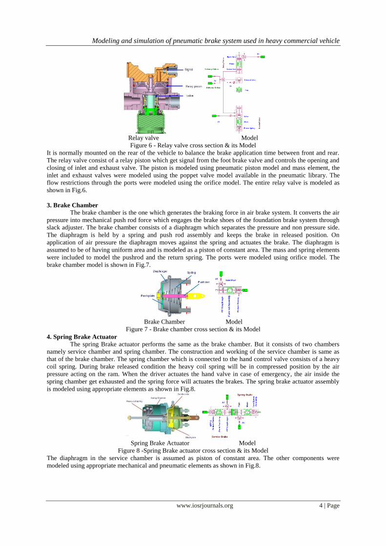
Relay valve Model
Figure 6 - Relay valve cross section & its Model
It is normally mounted on the rear of the vehicle to balance the brake application time between front and rear.
The relay valve consist of a relay piston which get signal from the foot brake valve and controls the opening and
closing of inlet and exhaust valve. The piston is modeled using pneumatic piston model and mass element, the
inlet and exhaust valves were modeled using the poppet valve model available in the pneumatic library. The
flow restrictions through the ports were modeled using the orifice model. The entire relay valve is modeled as
shown in Fig.6.
3. Brake Chamber
The brake chamber is the one which generates the braking force in air brake system. It converts the air
pressure into mechanical push rod force which engages the brake shoes of the foundation brake system through
slack adjuster. The brake chamber consists of a diaphragm which separates the pressure and non pressure side.
The diaphragm is held by a spring and push rod assembly and keeps the brake in released position. On
application of air pressure the diaphragm moves against the spring and actuates the brake. The diaphragm is
assumed to be of having uniform area and is modeled as a piston of constant area. The mass and spring elements
were included to model the pushrod and the return spring. The ports were modeled using orifice model. The
brake chamber model is shown in Fig.7.
Brake Chamber Model
Figure 7 - Brake chamber cross section & its Model
4. Spring Brake Actuator
The spring Brake actuator performs the same as the brake chamber. But it consists of two chambers
namely service chamber and spring chamber. The construction and working of the service chamber is same as
that of the brake chamber. The spring chamber which is connected to the hand control valve consists of a heavy
coil spring. During brake released condition the heavy coil spring will be in compressed position by the air
pressure acting on the ram. When the driver actuates the hand valve in case of emergency, the air inside the
spring chamber get exhausted and the spring force will actuates the brakes. The spring brake actuator assembly
is modeled using appropriate elements as shown in Fig.8.
Spring Brake Actuator Model
Figure 8 -Spring Brake actuator cross section & its Model
The diaphragm in the service chamber is assumed as piston of constant area. The other components were
modeled using appropriate mechanical and pneumatic elements as shown in Fig.8.

Modeling and simulation of pneumatic brake system used in heavy commercial vehicle
www.iosrjournals.org 5 | Page
5. Foundation Brake The foundation brake is the one which converts the actuation force from the actuator into braking
torque and stops the vehicle[8]. In India most of the heavy commercial vehicles use drum brakes, which
nowadays were being replaced by disc brakes.
5.1 Drum brakes
A drum brake is a brake that uses friction caused by a set of shoes or pads that press against a rotating drum-
shaped part called a brake drum. The drum brake and its design parameters were shown in Fig 9. The governing
equations for the torque generated by the drum brake is as follows
Figure 9- Drum Brake and its design parameters
Due to no availability of appropriate element to model the brake shoe the drum brake is modeled using the
signal libraries based on equation (3) and is shown in the Fig.10 [9] .
Figure 10 -Drum Brake AMESim Model
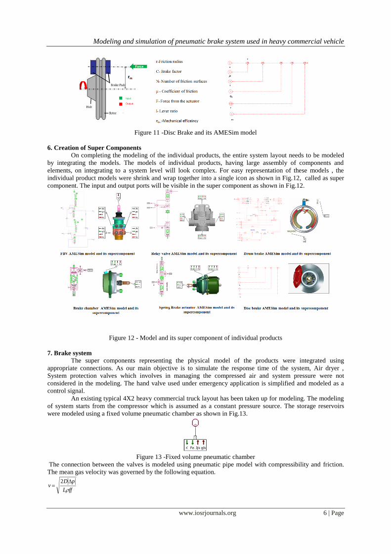
5.2 Disc brakes
A disc brake is a wheel brake which slows rotation of the wheel by the friction caused by
pushing brake pads against a brake disc with a set of calipers. The disc brake and its design parameters were
shown in Fig 11 along with its AMESim model. The disc brake is modeled using the signal library based on the
governing equation (4).
3
sin
coscos
sinsin
21
2
2 2
1
a
a
a
a
brp
dbrp
rdNT
4 lCFM mB
Modeling and simulation of pneumatic brake system used in heavy commercial vehicle
www.iosrjournals.org 6 | Page
Figure 11 -Disc Brake and its AMESim model
6. Creation of Super Components
On completing the modeling of the individual products, the entire system layout needs to be modeled
by integrating the models. The models of individual products, having large assembly of components and
elements, on integrating to a system level will look complex. For easy representation of these models , the
individual product models were shrink and wrap together into a single icon as shown in Fig.12, called as super
component. The input and output ports will be visible in the super component as shown in Fig.12.
Figure 12 - Model and its super component of individual products
7. Brake system
The super components representing the physical model of the products were integrated using
appropriate connections. As our main objective is to simulate the response time of the system, Air dryer ,
System protection valves which involves in managing the compressed air and system pressure were not
considered in the modeling. The hand valve used under emergency application is simplified and modeled as a
control signal.
An existing typical 4X2 heavy commercial truck layout has been taken up for modeling. The modeling
of system starts from the compressor which is assumed as a constant pressure source. The storage reservoirs
were modeled using a fixed volume pneumatic chamber as shown in Fig.13.
Figure 13 -Fixed volume pneumatic chamber
The connection between the valves is modeled using pneumatic pipe model with compressibility and friction.
The mean gas velocity was governed by the following equation.
ffL
pDv
2

Modeling and simulation of pneumatic brake system used in heavy commercial vehicle
www.iosrjournals.org 7 | Page
where
v -Mean gas velocity (m/s)
D- Diameter of the pipe (m)
Δp- Pressure drop (Pa)
L- Length of the pipe (m)
ρ - Density (kg/m3)
ff- Friction factor
Figure 14. 4X2 vehicle brake system layout with drum brake
The reservoir is connected to the supply ports of the brake valve by pipe connection. The rear of the vehicle is
having a relay valve. The primary delivery of the brake valve was connected to the relay valve. The delivery of
the relay valves was connected to the service side of the spring brake actuators. The secondary delivery of the
brake valve was connected directly to the brake chambers in the front axles of the vehicle Refer Fig.14. The
actuators were connected to the foundation brake model, drum brake (Fig.14) and Disc Brake (Fig.15)
Figure 15 4X2 vehicle brake system layout with disc brake
The design parameters of the valves and actuators were given and a typical 16 ton vehicle layout with drum
brake was taken up for study. The pipe dimensions of the brake system layout were given as input. In the second
model (Fig.15) the drum brakes were replaced with disc brake of equivalent size available in the market.
Figure 16 -Signal input to the brake system

Modeling and simulation of pneumatic brake system used in heavy commercial vehicle
www.iosrjournals.org 8 | Page
The driver foot pedal effort was give as plunger displacement of the brake valve. The signal was given such that
the total travel of plunger was achieved within 0.2 seconds (Fig.16) as per the vehicle standard requirements [1].
Figure 17 - Pressure response curve in the spring brake actuator
The simulation was carried out and the response time was measured by capturing the pressure built-up in the
rear, Spring Brake Actuator (least favorable chamber [1]). The pressure response curve was shown in Fig.17
which we got from the Spring brake actuator end. The transient torque generated in both the cases vehicle with
drum brake and the same vehicle replaced with equivalent disc brake. Fig.18 shows that on replacing the
existing drum brake with equivalent disc brake can generate more torque and can achieve better stopping
distance.
Figure 18 -Pressure response curve in the spring brake actuator
IV. CONCLUSION The Brake system model considering all the design parameters was done. A typical 4X2 heavy
commercial vehicle having pneumatic brake system with drum brake was taken up for simulation. The response
time of the system and the transient torque with drum brake were carried out. The same layout on replacing with
an equivalent disc brake shows better torque characteristics. On replacing the drum brake with disc brake the
vehicle will have better stopping distance.
The brake system model was flexible enough to study the role of individual valves in system response.
Apart from this the model can be further expanded for design and optimization of brake system layout for other
heavy commercial vehicle having multi axles. This approach will significantly reduce the overall system design
lead time when compared to the conventional method.
Further this can be extended to vehicle modeling along with the foundation brakes and the stopping
distance of the vehicle can be simulated.
Acknowledgements I express my gratitude to Dr. M Senthil Kumar, professor, Department of Automobile engineering,
Madras Institute of Technology, Anna University, Chennai for allowing me to do the project and continuous
encouragement for doing this project work. I also wish to express my deep sense of gratitude to Mr. S.
Narayanan, Head of the Department, R&D, WABCO INDIA Ltd., Chennai, for giving me an opportunity to do
the project in the industry research environment

Modeling and simulation of pneumatic brake system used in heavy commercial vehicle
www.iosrjournals.org 9 | Page
REFERENCES [1] IS 11852_4 "Automotive Vehicles - Brakes and Braking system", Indian Standard, 2001 [2] Sridhar,S.,Narayanan,S.,Kumaravel,B.,"Dynamic Simulation of Brake valve in Air Brake System" SAE paper No.2009-28-0030.
[3] Jinglai, Wu., Hongchang, Zhang., Yunqing, Zhang. and Liping, Chen., "Robust Design of a Pneumatic Brake System in Commercial
Vehicles" SAE paper No.2009-01-0408 [4] Li He, Xiaolong Wang, Yunqing Zhang, Jinglai Wu, Liping Chen" Modeling and Simulation Vehicle Air Brake System"
Proceedings 8th Modelica Conference, Dresden, Germany, March 20-22, 2011
[5] Zbigniew, Kulesza., Franciszek, Siemieniako.," Modeling the air brake system equipped with the brake and relay valves" Scientific Journals, Maritime University of Szczecin Vol.24,pp 5-11,2010.
[6] Acarman, T., Ozguner, U., Hatipoglu, C., and Igusky, A., "Pneumatic Brake System Modeling for Systems Analysis," SAE Paper
No.2000-01-3414. [7] "AMESim Handbook", LMS Imagine S.A. 1995-2012
[8] Subramanian, S.C., Darbha, S. and Rajagopal, K.R., "Modeling the Pneumatic Subsystem of an S-cam Air Brake System" Journal of
Dynamic Systems, Measurement and Control ASME Vol.126, pp36-46,2004 [9] Shigley, Mechanical Engineering Design (McGraw-Hill ,2008) 812-817