modeling and representation 1 – comparative review and polygon mesh models 2.1 introduction 2.2...
TRANSCRIPT

Modeling and representation 1 – comparative review and polygon mesh models
2.1 Introduction
2.2 Polygonal representation of three-dimensional objects
2.3 High-level methods – constructive solid geometry
2.4 High-level creation using modellers/ediotrs

2.1 Introduction Modelling and representation is a general phrase which c
an be applied to any or all of the following aspects of objects: Creation of a three-dimensional computer graphics representati
on The technique or method or data structure used to represent the
object Manipulation of the representation – in particular changing the
shape existing model.

2.1 Introduction The representation of an object is very much an unsolved
problem in computer graphics Representation for user or for renderer
Polygon mesh representation :both Bi-cubic parametric patches and constructive solid geometry (C
SG): for user, it may be converted into polygon meshes for rendering

2.1 Introduction Different representational methods have their advant
ages and disadvantages. There is no universal solution to the many problems . Particular modelling methods have evolved for parti
cular contexts.

2.1 Introduction Mainstream models used in computer graphics
Polygonal Bi-cubic parametric patches CSG (constructive solid geometry) Spatial subdivision techniques Implicit representation

2.1 Introduction Polygonal
Objects are approximated by a net or mesh of planar polygonal facets.
With this form we can represent, to an accuracy that we chose, an object of an shape.
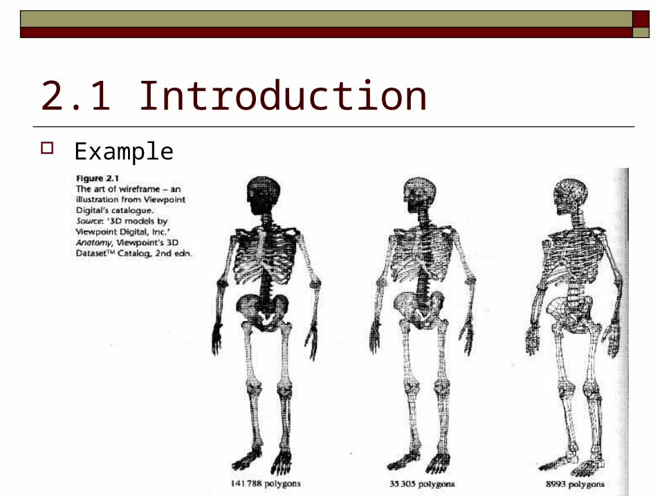
2.1 Introduction Example

2.1 Introduction Bi-cubic parametric pathes
These are “curved quadrilaterals”.
Each patch is specified by a mathematical formula that gives the position of the patch in 3D space and its shape.
A significant advantage of the representation is its ecnomy.

2.1 Introduction Example
Polygon mesh (2048 elements)
Patch (32 patches)

2.1 Introduction CSG (constructive solid geometry)
This in an exact representation to within certain rigid shape limits.
The CSG method is a volumetric representation – shape is represented by elementary volumes or primitives

2.1 Introduction Example

2.1 Introduction Spatial subdivision techniques
This simply means dividing the object space into elementary cubes, known as voxels.
Labelling each voxel as empty or as containing part of an object.

2.1 Introduction Implicit representation
Surfaces defined by underlying mathematical formula An implicit function is, for example: (which is definition for a sphere)
2222 rzyx

2.1 Introduction Example

2.2 polygonal representation of three-dimensional objects2.2.1 creating polygonal objects
2.2.2 manual modelling of polygonal objects
2.2.3 automatic generation of polygonal objects
2.2.4 interactive/mathematical generation of polygon objects

2.2 polygonal representation of three-dimensional objects This is the classic representational form in 3D graphics Advantage
creating polygonal objects is straightforward visually effective algorithms exist highly efficient renderer simpler elements
Disadvantage complex and high creation cost do not allow simple shape manipulation hard to do exact collision detection accuracy

2.2 polygonal representation of three-dimensional objects Hierarchical structure
vertex-based boundary model representing faces in terms of a sequences of vertices
edge-based boundary model representing faces in terms of a closing sequence of
edges

2.2 polygonal representation of three-dimensional objects Conceptual hierarchy

2.2 polygonal representation of three-dimensional objects Topological representation

2.2 polygonal representation of three-dimensional objects Practical data structure
2.2 polygonal representation of three-dimensional objects Attribute
Polygon attribute Edge attribute Vertex attribute

2.2 polygonal representation of three-dimensional objects Polygon attributes
Triangular or not Area Normal to the plane containing the polygon Coefficients (A,B,C,D) of the plane containing th
e polygon where Ax + By + Cz + D=0 Whether convex or not Whether it contain holes or not

2.2 polygonal representation of three-dimensional objects Edge attributes
Length Whether it is an edge between two polygons or an
edge between two surfaces Polygons on each side of the edge
2.2 polygonal representation of three-dimensional objects Vertex attribute
Polygons that contribute to the vertex Shading or vertex normal – the average of the nor
mals of the polygons that contribute to the vertex Texture coordinates (u,v) specifying a mapping in
to a two-dimensional texture image
2.2 polygonal representation of three-dimensional objects Another problems
Scale problem: the needs to control the detail of objects Solution : maintain a hierarchy of models in different
detail and use the one appropriate. Problem s to be solved:
Visual disturbances How to generate the hierarchy How many levels

2.2.1 Creating polygonal objects Four common examples of polygon modelling methods:
Using a three-dimensional digitiser or adopting an equivalent manual strategy
Using an automatic device such as a laser ranger Generating an object from a mathematical description Generating an object by sweeping

2.2.2 manual modelling of polygonal objects The easiest way to model a real object is manually using a three-dimensional
digitiser.

2.2.3 Automatic generation of polygonal objects A device that is capable of creating very accurate or high-resolution polygon
mesh objects from real objects is a laser ranger.

2.2.4 Interactive/mathematical generation of polygon objects Many polygonal objects are generated through an
interface into which a user puts a model description in the form of a set of curves.
The most popular paradigm is that of sweeping a cross-section in a variety of different ways.

2.2.4 Interactive/mathematical generation of polygon objects Examples

2.2.4 Interactive/mathematical generation of polygon objects Synder’s rail curve product surfaces

2.2.4 Interactive/mathematical generation of polygon objects Synder’s Affine Transformation Surface

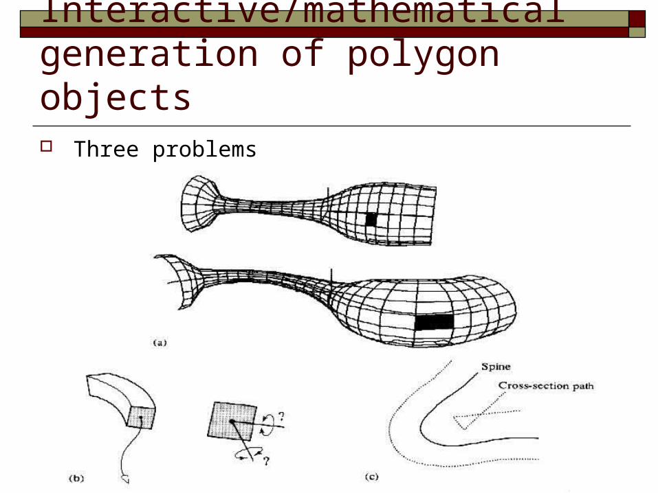
2.2.4 Interactive/mathematical generation of polygon objects Three problems
The size of the polygonal primitives depends on the excursion of the spine curve.
How do we orient the cross-section with respect to a varying spine.
How do we prevent cross-sections self-intersecting
2.2.4 Interactive/mathematical generation of polygon objects Three problems

2.2.4 Interactive/mathematical generation of polygon objects Solve problem1
The more polygons occur when the curvature twists rapidly.
The most direct way to do this is to use the curve subdivision algorithm and subdivide the curve until a linearity test is positive.

2.2.4 Interactive/mathematical generation of polygon objects Solve problem2 (Frenet frame)
The unit length tangent vector T:
The derivative of the curve V:
The principal normal N:
The second derivative of the curve A:
B:
VVT
cbuauV 23 2
4:V
VAVKwhereK
KN
bauA 26
NTB

2.2.4 Interactive/mathematical generation of polygon objects Solve problem2 (Frenet f
rame)
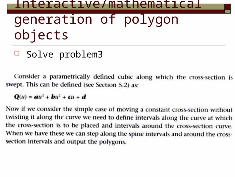
2.2.4 Interactive/mathematical generation of polygon objects Solve problem3

2.3 High-level methods – constructive solid geometry (CSG) The CSG approach is a powerful high-level tool that is found in
many modelling packages. It does not manipulate polygons directly but produces polygon
models after the modelling or design phase is complete. The logic of the shape in this representation is in how the final s
hape can be made or represented as a combination of primitive shapes.

2.3 High-level methods – constructive solid geometry (CSG) Motivation
Facilitate an interactive mode for solid modelling
Object representation Primitives are combined using Boolean set operators and l
inear transformations An object representation is stored as an attributed tree.
Disadvantage High rendering cost Limited primitives and operators
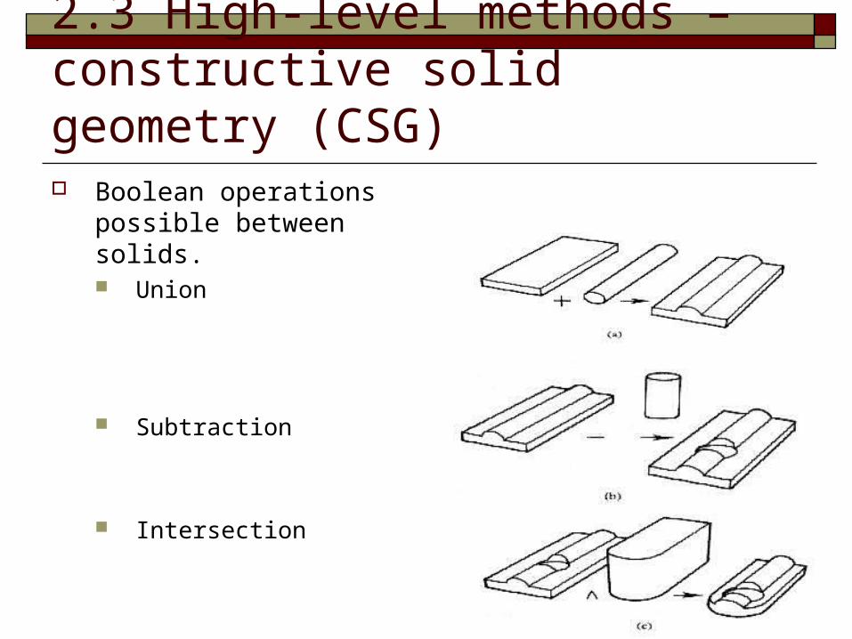
2.3 High-level methods – constructive solid geometry (CSG) Boolean operations possible
between solids. Union
Subtraction
Intersection

2.3 High-level methods – constructive solid geometry (CSG) CSG tree

2.3 High-level methods – constructive solid geometry (CSG) Geometric complex objects

2.4 High-level creation using modellers/editors The previous sections described modelling methods that
are commonly embedded in modellers/editors. Such software will generally contain many high-level fac
ilities.

2.4 High-level creation using modellers/editors Example

2.4 High-level creation using modellers/editors

2.4 High-level creation using modellers/editors