model view definitions for precast...
TRANSCRIPT

Model View Definitions for Precast Concrete
PPrreeccaasstt CCoonnccrreettee BBIIMM SSttaannddaarrdd DDooccuummeennttss
VVoolluummee II
MMooddeell VViieeww DDeeffiinniittiioonnss
Page 1

Model View Definitions for Precast Concrete
Executive Overview This is an intermediate release of the Model View Definitions for data exchanges of precast concrete information. It outlines the MVDs in three volumes:
- Volume 1 (this volume): Overview, with specification of Exchange Models for use various use cases and the High Level Concepts making up the Exchange Models. These define what information is to be included in the exchanges and to what level of detail. They are presented in Model View Definition (MVD) diagrams.
- Volume 2 contains the detailed binding definitions for all of the exchange concepts that are used in the diagrams of volume 1. These are IFC 2x4 bindings, and graphic depictions of the IFC entities and property sets used with their relationships, implementation rules, figures showing typical situations in precast buildings, and Part 21 file examples using EXPRESS. All of these are also available on the “IFC Solutions Factory” IAI MVD website, at http://blis-project.org/IAI-MVD/.
- Volume 3 contains the detailed binding definitions for all of the exchange concepts that have been defined by other groups developing MVDs and that are re-used in the MVDs of volume 1. All of these are also available on the “IFC Solutions Factory” IAI MVD website, at http://blis-project.org/IAI-MVD/.
The MVD is based on the functional specification called an Information Delivery Manual (IDM), completed in January, 2009, under this contract. This Model View Definition (MVD) specifies at the implementation level the information needed to support the workflows defined in the IDM, covering the major digital exchanges dealing with precast concrete. The exchanges are defined to be implemented using the Industry Foundation Classes (IFC) model schema. The IFC bindings will support a set of standard export and import exchange capabilities for commercial software products, enabling seamless exchange of digital information and enhancing work processes. A particular exchange will depend on varied subsets of the overall model data. Thus these subsets or modules will be used selectively in multiple different contexts. We adopt the idea of information ‘Concepts’ to represent the information items in a way that allows them to be composed for different workflow cases. Implementers can re-use the software modules and testing and certification of modules may also possible. The notion of Concepts has grown from previous implementation activities, led by the BLIS effort in the early 2000s. The Concepts are drawn directly from the Information Delivery Manual (IDM) that was prepared by the Precast Concrete BIM Project team, including the PCI Advisory Board and the Technical Support Team. The Concepts include such varied issues as the degree of detail needed, connectivity, aggregation and nesting relationships, type of geometry representation, and others used in different workflows. Our Concepts were also drawn from a library of Concepts that have been proposed or defined by other BIM standard efforts in the IFC Solutions factory website: (http://www.blis-project.org/IAI-MVD/). These Conceptsare available for possible re-use and some of them may have already been implemented by BIM software companies. The Concepts for any domain such as precast form a hierarchical lattice, from high-level aggregated Concepts to leaf ones, the leaves providing bindings to IFC (e.g., the associated IFC implementation code). Most of the bindings are based on the new 2.x4, currently in beta release, available on
Page 2

Model View Definitions for Precast Concrete
the buildingSMART website: http://www.iai-tech.org/products/ifc_specification/ifc-releases/ifc2x4-release/beta1-release. The current diagrams start with the IDM requirements from which they were derived. These are followed by the Concept structures need to support those functions. These are then associated with the leaf bindings to IFC, using a diagramming method that is widely used within the IFC community. In many cases, certain information about a precast piece needs to have different representation and these alternatives are included in the Concept bindings. This initial draft addresses the Priority One and Priority Two implementations agreed to at the April 24-25 meeting. It is being reviewed to gain feedback from both precast concrete information users and from software implementers regarding definitional issues and adequacy of documentation. The current bindings reflect the technical team’s judgment regarding best implementation of the IDM requirements. These will be reconciled, as needed, with software implementation capabilities and limitations.
Page 3

Model View Definitions for Precast Concrete
Model View Definitions
Name Model Exchange for Precast
Change Log
8-September-09 Version 2.1 for draft review by PCI BIM Committee
[email protected] Version 2.0 for draft review by PCI
BIM Committee [email protected]
[email protected] Version 1.0 for draft review by PCI
BIM Committee [email protected]
16-Apr-09 Version 0.5 for draft review by PCI
BIM Committee c
(all) Model Views
Page 4
Model View Definitions for Precast Concrete
TABLE OF CONTENTS
....................................................................................................................................... 2 EXECUTIVE OVERVIEW
................................................................................................................................. 4 MODEL VIEW DEFINITIONS
...................................................................................................................................................... 7 BACKGROUND
.................................................................................................................................................... 9 MVD OVERVIEW
.............................................................................................................................................................. 9 PURPOSE.................................................................................................................................................... 9 MVD DIAGRAMS
...................................................................................................................................................... 10 IFC BINDINGS
CANDIDATE EXCHANGES FOR IMPLEMENTATION IN PRIORITY ONEERROR! BOOKMARK NOT DEFINED.
.......................................... ERROR! BOOKMARK NOT DEFINED. 1. [INTEGRATED EM.1] CONCEPT MODEL EXCHANGES........................... ERROR! BOOKMARK NOT DEFINED. 2. [INTEGRATED EM.5] ARCHITECTURAL CONSTRUCTION MODEL
........... ERROR! BOOKMARK NOT DEFINED. 3. [INTEGRATED EM.51] CONSTRUCTION COORDINATION MODEL (PARTIAL)
............................................................................ 12 GENERAL MVD DIAGRAMS NOT SPECIFIC TO PRECAST
................................................................................. Error! Bookmark not defined. Site Contained in Project................................................................... Error! Bookmark not defined. Spatial Structure - Building in Site
.................................................................................................. Error! Bookmark not defined. Site Perimeter................................................. Error! Bookmark not defined. Spatial Structure - Building Storey in Building
.............................................................. Error! Bookmark not defined. Spatial Structure - Space in Building.................................................... Error! Bookmark not defined. Spatial Structure - Space in Building Storey
.................................................................. Error! Bookmark not defined. Grid and Grid Axis Representation....................................................................................... Error! Bookmark not defined. Grid Axis Assignment
................................................................. Error! Bookmark not defined. Grid Placement in Spatial Structure
.............................................................................................................. 19 PRECAST SPECIFIC MVD DIAGRAMS
...................................................................................................... 19 TYPES AND INSTANCES IN THE PRECAST MVD............................................................................................................................................ 22 PRECAST PIECES............................................................................................ Error! Bookmark not defined. Element Attributes
............................................................................... Error! Bookmark not defined. Element Type Assignment.................................................................... Error! Bookmark not defined. Precast Property Set Assignment
............................................................................... Error! Bookmark not defined. Precast General Attributes..................................................................................... Error! Bookmark not defined. PropertySet Definition:
......................................................................................... Error! Bookmark not defined. Property Definitions:.......................................................................... Error! Bookmark not defined. Precast Fabrication Attributes
..................................................................................... Error! Bookmark not defined. PropertySet Definition:......................................................................................... Error! Bookmark not defined. Property Definitions:
.............................................................................. Error! Bookmark not defined. System Piece Aggregation............................................................................................. Error! Bookmark not defined. Actor Assignment
....................................................................................... Error! Bookmark not defined. Approval Assignment................................................................. Error! Bookmark not defined. Precast Piece Material Association
............................................................................. Error! Bookmark not defined. Precast Piece Containment.......................................................................................... Error! Bookmark not defined. Relative Placement......................................................................................... Error! Bookmark not defined. Absolute Placement
.............................................................................. Error! Bookmark not defined. Placement Relative to Grid....................................................................... Error! Bookmark not defined. Generic Shape Representation....................................................................... Error! Bookmark not defined. Generic Brep Shape Geometry
.............................................................................ERROR! BOOKMARK NOT DEFINED. PRECAST PIECE TYPE
......................................................................... Error! Bookmark not defined. Precast Piece Type Attributes.................................................................. Error! Bookmark not defined. Piece Type Geometry Assignment
.............................................................................. Error! Bookmark not defined. Precast Piece Aggregation
Page 5

Model View Definitions for Precast Concrete
.....................................................................ERROR! BOOKMARK NOT DEFINED. NON-PRECAST ELEMENTS
..... 48 APPENDIX A: BUILDING ENTITY SUBTYPES FOR PRECAST PIECES AND PRECAST PIECE TYPES
Page 6

Model View Definitions for Precast Concrete
Background The National Building Information Model Standard (NBIMS) is a set of interoperability standards for exchange of facility and infrastructure data throughout the life-cycle of a project. NBIMS is a joint project coordinated by the National Institute of Building Sciences (NIBS) and the buildingSMART Alliance, a working committee within NIBS, in conjunction with many other facilities-related associations and software companies worldwide. The goal of the project within which this document was produced is to develop a national BIM standard for precast concrete design, engineering, fabrication and erection. The method of this work is to define first, the user functional requirements in a report called an Information Delivery Manuals (IDM). It was completed in January, 2009, and provided four process models that covered four distinct workflows, reflecting different project procurement methods and construction types (architectural and structural). Each of the process models was used to functionally define the information content required in each exchange. Based on the IDM specifications, the Model View Definitions (MVD) are defined for the significant communication and data exchanges associated with all use cases associated with precast concrete. The primary orientation is that of the precast concrete fabricator. The project is funded by the Charles Pankow Foundation and the Precast/Prestressed Concrete Institute (PCI).This project was preceded by a feasibility study sponsored by the Charles Pankow Foundation to determine the issues of information exchange, focusing on architectural precast. This work has grown from and expands upon that study. Working teams were formed within the membership of the industry BIM Advisory Committee, which functions under the auspices of the Precast/Prestressed Concrete Institute to provide the domain expertise for this endeavor. The initial step was to define the IDM use case specification. Now, the MVD are being specified and communicated with both the advisory committee for functional correctness and with software implementers. The members of each of the four working teams are listed in the following table. Their contributions are gratefully acknowledged.
Page 7

Model View Definitions for Precast Concrete
PCI BIM Advisory Committee Working Teams Chair: Michael LaNier BERGER/ABAM Engineers Inc.
A. Projects led by Precasters: B. Projects where Precaster is a subcontractor:
1. Jason Lien - chair Encon United 2. Jennifer Huber Encon United 1. Michael Slobojan – chair Structureworks 3. Monty Overstreet FDG, Inc 2. Mark Potter Finfrock Industries 4. Mike Sloter IPC Inc 3. Davis Chauviere HKS Inc 5. Mark Kraft CEG Engineers 4. Charles Pool Tekla
5. Dieter Maucher Tindall Corporation 6. Jim Davis Stresscon
D. Fabrication through Erection: C. Architectural Precast: 1. Mike Putich - chair 1. David Orndorff - chair Shockey Precast 2. Dan van Vieren Concrete Vision 2. John Wang Mid State Precast 3. Wayne Norris Metromont 3. Mike LaNier BERGER/ABAM
Engineers Inc. 4. AJ Scarfato Metromont 5. Earle Kennett NIBS 4. Aaron Fink Oldcastle Precast 6. Wayne Kassian Kassian Dyck& Assoc 7. Karen Laptas Blue Ridge Design, Inc.
Technical Advisory Team: Chuck Eastman Georgia Tech Rafael Sacks Technion, Israel Institute of Technology Ivan Panushev Georgia Tech Shiva Aram Georgia Tech Manu Venugopal Georgia Tech Technical Consultants: Richard See Digital Alchemy Thomas Liebich AEC3
Page 8

Model View Definitions for Precast Concrete
MVD Overview
Purpose This Model View Definition (MVD) specifies for the precast concrete domain the digital information needed to support the exchanges in a variety of workflow ‘use cases’. This MVD also prescribes implementation bindings using the Industry Foundation Classes (IFC) model schema. The IFC bindings are intended for software developers to implement a set of standard export and import exchange capabilities for their commercial software products, which will in turn enable seamless exchange of digital information in multiple precast concrete workflows. Because there are multiple possible workflows, and selection of a particular exchange will depend on particular work practices and project contexts, the approach is modular: exchange models are composed of different information items at different possible degrees of detail. Accordingly, we have defined information ‘Concepts’ as modules to represent the information items in a way that allows them to be composed for different workflow cases and implementers to re-use software modules and makes modular testing possible. The Concepts are drawn directly from the Information Delivery Manual (IDM) that was prepared by the Precast Concrete BIM Project team, which included domain experts (organized in a Precast BIM Committee sponsored by the Precast Concrete Institute (PCI) and chaired by Mike LaNier), and technical advisors (in a team led by Prof. Chuck Eastman at Georgia Tech). The IDM document defined the functional requirements for data exchanges needed for precast concrete design, fabrication and construction, defined as Exchange Models (EMs). For each EM defined in the IDM, the information requirements were defined and related to the Concepts needed for that exchange. The parameters included such issues as the degree of detail needed, connectivity, material properties, aggregation and nesting relationships, type of geometry representation, and others. Concepts were also drawn from a library of Concepts that have been proposed or defined in the IFC Solutions factory website: (http://www.blis-project.org/IAI-MVD/). These are the Concepts developed by other BIM standard efforts and available for possible re-use..
MVD Diagrams The exchange requirements expressed in the IDM formed the basis for preparation of this MVD document. The MVD lays out the Concepts. The Concepts serve as “building blocks” for composing the use cases associated with particular workflows. The Concepts reflect both the initial functional requirements defined in the IDM and their binding to an implementation, using the Industry Foundation Classes schema. Concepts are also aggregated into higher level Concepts that are also available for re-use. Only the base-level Concepts contain a mapping to modular implementation units – or bindings -- expressed in the diagrammed IFC format In line with the practice adopted in earlier MVD projects, we distinguish three kinds of Concepts: variable, adaptor and static. The Static Concepts are re-usable bottom level mappings to IFC structures, and are re-used as needed in different contexts. Static Concepts are composed together to define the higher-level modular units (called Variable Concepts). Where needed, mid-level ‘Adaptor Concepts’ are used to collect Static Concepts together and associate them as groupings within the Variable Concepts. The top level Variable Concepts are full object or relation definitions and bindings. In the following diagrams, each Concept is defined in a rectangle and numbered in the upper left with prefix designating which project authored them. All the Concepts and binding defined by this project team are labeled “PCI”. The numbers for the PCI Concepts may change over time, as they are re-assigned in the IFC Solutions Factory as they are uploaded.
Page 9

Model View Definitions for Precast Concrete
Globally, Concepts are represented in a lattice, where different Concepts are re-used in different workflows. This would be too complex to diagram. So top level Concepts are defined into lower level ones that identify a context for use. These define the function and semantics required for the medium level Concepts .These are called Adapter Concepts. Sometimes, special use or “business rules” apply to the Adapter Concepts In most places there are multiple levels of Adapter Concepts. The variable and adapter Concepts provide good reference to the information concepts making up a particular use case or Exchange Model, for review by the domain users. At the bottom are Leaf Concepts and these have IFC bindings. They identify the specific IFC constructs used to implement the Leaf Concepts. These are of critical importance to software companies and their implementers. There are often multiple Variable or Leaf Concepts to represent an object or shape or properties, for use in different workflow contexts. These may represent alternative geometric representations to use in different contexts, or different property sets. These are also grouped together in this report, so the variations in implementation and intended use can be more easily seen. Most of the bindings identified here use IFC constructs from Release 2.x4. Some of the bindings identified in this report are based on IFC entities that have only recently been added to the draft IFC 2x4 release. Because of this structure, we have grouped the high level variable and adapter Concepts with this Overview, for use by all users and implementers. The Precast Bindings, including the new ones developed by this group as extensions to IFC Release 2.x3, are included in Volume Two. The Concepts defined previously and available from other specification groups from the IFC Solution Factory, are replicated for implementers in Volume Three. Concepts have the following coding:
3. Exchange Model Views In the next version of this report, when all the Concepts have been defined, this section will include the mapping of Concepts to EMs, identifying the information contents to be supported for each use case defined in the IDM. This version omits these mappings because the Concepts are incomplete.
Page 10
Model View Definitions for Precast Concrete
Page 11
Model View Definitions for Precast Concrete
Page 12
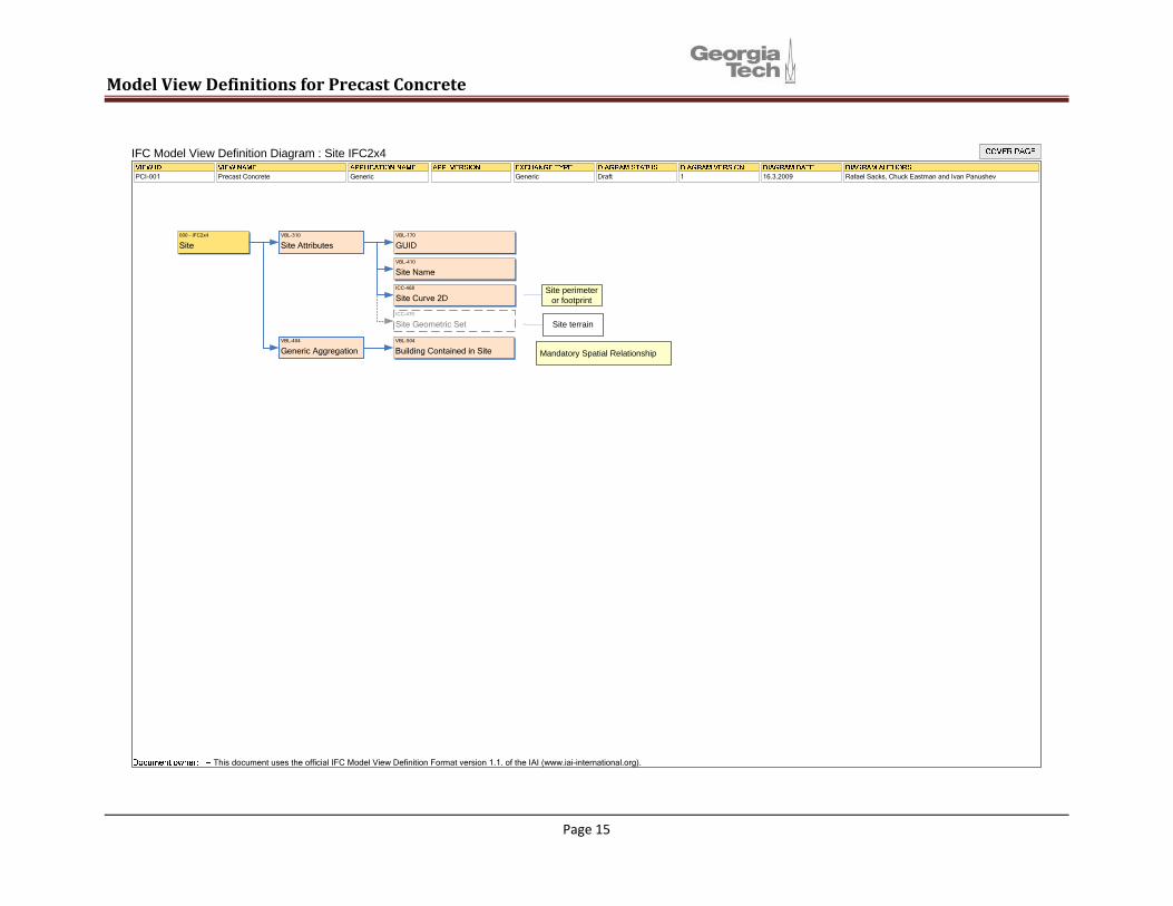
General MVD Diagrams not Specific to Precast The MVD specifications in this section are part of all IFC Exchanges. They place all objects in a building Spatial Composition structure used to access and structure a project. The section also defines project-level layout grids that may be used in the placement of all systems, and the key elements of metadata that are commonly used (such as review and approval status for precast pieces), The following set of diagrams first deals with overall project information, not specific to precast. The diagrams define an overall spatial access hierarchy specified within the IFC structure. This is Project – Site – Building – Building Storey – Space, which have been defined by others. The building is the top level aggregator for different systems – structural, HVAC, etc. Thus it carries references to the precast pieces through this structure. Storey and Spaces are the means to identify building spaces so as to represent their live loads and allow those loads to be associated with the appropriate elements and nodes of the structure. Next, the diagrams define the grid structures that may be used for relative placement. Finally, they define metadata, for addressing who is the author on objects, and provide space for status information. Like all MVD diagrams, each model view includes a reference to the IDM requirements, has a description as an MVD Concept Diagram. The IFC2x4 Binding Documents are available in Volumes II and III.

Model View Definitions for Precast Concrete
Page 13

Model View Definitions for Precast Concrete
Page 14
Model View Definitions for Precast Concrete
Site perimeteror footprint
Site terrain
Mandatory Spatial Relationship
VBL-310
Site AttributesVBL-170
GUID
VBL-410
Site Name
ICC-468
Site Curve 2D
ICC-470
Site Geometric Set
VBL-404
Generic AggregationVBL-504
Building Contained in Site
000 - IFC2x4
Site
IFC Model View Definition Diagram : Site IFC2x4
PCI-001 Precast Concrete Generic Generic Draft 1 16.3.2009 Rafael Sacks, Chuck Eastman and Ivan Panushev
This document uses the official IFC Model View Definition Format version 1.1. of the IAI (www.iai-international.org).
Page 15

Model View Definitions for Precast Concrete
Page 16

Model View Definitions for Precast Concrete
Can be Non-precast Structural System, Non-precast Façade System or Generic Building System
Optional Spatial Relationshipp
VBL-170
GUID
VBL-404
Generic Aggregation
VBL-416
Aggregates Structural Analysis Models
PCI-046
Space Contained in Building Storey
PCI-012
System Serves Building Storey
VBL-413
Building Storey Attributes
VBL-414
Building Storey Name
PCI-007
Assigns Precast Structural System
PCI-009
Assigns Other Building System
- IFC2x4
Building Storey
IFC Model View Definition Diagram : Building Storey IFC2x4
PCI-001 Precast Concrete Generic Generic Draft 1 16.3.2009 Rafael Sacks, Chuck Eastman and Ivan Panushev
This document uses the official IFC Model View Definition Format version 1.1. of the IAI (www.iai-international.org).
Page 17

VBL-085
Grid AttributesVBL-170
GUID
PCI-047
Grid Name
PCI-048
Grid Representation
PCI-049
Grid Spatial Structure Containment
PCI-050
Grid Axis Assignment
- IFC2x4
Grid
IFC Model View Definition Diagram : Grid IFC2x4
PCI-001 Precast Concrete Generic Generic Draft 1 16.3.2009 Rafael Sacks, Chuck Eastman and Ivan Panushev
This document uses the official IFC Model View Definition Format version 1.1. of the IAI (www.iai-international.org).
Page 18
View Definitions for Precast Concrete Model
Model View Definitions for Precast Concrete
Precast Specific MVD Diagrams
• The following section provides the specifications for precast specific model views, specified as Concepts. It is based on the IDM for Precast Concrete and includes reverences to the IDM requirements.
Each Concept Diagram describes all the Concepts needed for all its definition in different use cases. The subset of those used are defined in the EMs. The static Concepts, with their bindings are referenced alphabetically, in Volumnes II and III.
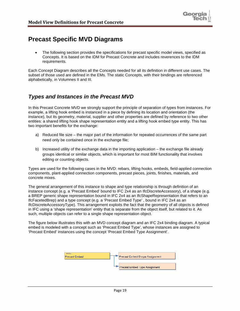
Types and Instances in the Precast MVD In this Precast Concrete MVD we strongly support the principle of separation of types from instances. For example, a lifting hook embed is instanced in a piece by defining its location and orientation (the instance), but its geometry, material, supplier and other properties are defined by reference to two other entities: a shared lifting hook shape representation entity and a lifting hook embed type entity. This has two important benefits for the exchange:
a) Reduced file size – the major part of the information for repeated occurrences of the same part need only be contained once in the exchange file;
b) Increased utility of the exchange data in the importing application – the exchange file already groups identical or similar objects, which is important for most BIM functionality that involves editing or counting objects.
Types are used for the following cases in the MVD: rebars, lifting hooks, embeds, field-applied connection components, plant-applied connection components, precast pieces, joints, finishes, materials, and concrete mixes. The general arrangement of this instance to shape and type relationship is through definition of an instance concept (e.g. a ‘Precast Embed’ bound to IFC 2x4 as an IfcDiscreteAccessory), of a shape (e.g. a BREP generic shape representation bound in IFC 2x4 as an IfcShapeRepresentation that refers to an IfcFacetedBrep) and a type concept (e.g. a ‘Precast Embed Type’ , bound in IFC 2x4 as an IfcDiscreteAccessoryType). This arrangement exploits the fact that the geometry of all objects is defined in IFC using a ‘shape representation’ entity that is separate from the object itself, but related to it. As such, multiple objects can refer to a single shape representation object. The figure below illustrates this with an MVD concept diagram and an IFC 2x4 binding diagram. A typical embed is modeled with a concept such as ‘Precast Embed Type’, whose instances are assigned to ‘Precast Embed’ instances using the concept ‘Precast Embed Type Assignment’.
Page 19

Model View Definitions for Precast Concrete
Precast Embed
Precast Embed Shape Assignment
Precast Embed Type
Precast Embed Type Shape Representation
Precast Embed Type Assignment
Note that this arrangement is supported throughout even for situations where there is only one unique occurrence of an object in a model or an exchange. To conform to the general structure, a type instance of the object is created even if it is only referenced by a single located instance. This is true even for piece marks and pieces. Element types and instance is enforced if the exporting application models objects that conform to the type-instance structure. If elements are not structured in the exporting application in this manner, then this structure will not be exported. The precast piece and the precast piece mark are a special case, because there are two more levels of typology: typical beams (or columns, spandrels, etc.) and typical cross section profiles. The four concepts are as follows:
1. A Precast Piece is a specific occurrence of a prefabricated concrete beam, column, spandrel or other part of a building. It has a location that is defined within the building’s coordinate system and by a ‘location ID’. In some cases, such as double tees that form a slab, the support conditions may be designed to induce a ‘twist’ or ‘warp’ in the piece, thus the exchange information includes provision for communicating the geometric distortion, if any, by using a precast specific property set. These are the instances that are referred to in the discussion above. As such, they do not have their own geometry, although in some cases minor local adaptations, such as a specific hole blocked-out for a pipe to pass through the piece, can be defined locally.
2. A Piece Mark is a unique design for a precast piece. In precast fabrication practice, it is very common that multiple pieces are identical (or nearly identical) to one another. Instead of
Page 20

Model View Definitions for Precast Concrete
designing and drawing all of them, they are represented as a group by a single design, called a ‘Piece Mark’. A ‘Piece Mark’ is thus a collection of pieces that can be interchanged when installed. This aggregation is made within a design application. In the exchange, it is carried as an attribute of the piece itself (bound to use the ObjectType property of the IfcBuildingElement..
3. A Piece Type is a type of beam, column, hollow-core panel, or other member that is commonly produced by a precast fabricator. For example, a fabricator may maintain a catalog of typical hollow-core plank sections with standard prestress tendon patterns. Another example might be a typical 20”x20” column, of 30’ length, with a specific pattern of rebars stirrups; the same typical column may be used in configurations with corbels in different places, with different main rebars, etc. A designer could choose the same piece type for multiple piece marks, and multiple piece marks would share a common piece type. In an exchange, it is modeled as a Type, with reference to the discussion above. In an exchange, its properties can be detailed in one of two ways: a) by reference to an external data library that was shared among all parties to the exchange in advance; or b) by carrying explicit property set values for the piece type and by mapping to its own geometry (using a shape representation object), rebar arrangement and prestress tendon placement pattern. Alternatively, a piece mark may be defined by a piece type. In exchanges, piece types will reflect the method by which pieces and piece marks have been constructed.
4. A Piece Profile is a cross-section shape definition that can be commonly used for multiple piece types. They can be defined in libraries or catalogs and used as the basis for multiple piece type occurrences where extruded solid geometry is used.
Note also that piece marks and piece types can also make reference to other types, by containing instances of embeds, rebars, lifting hooks, joints, etc. which each in turn refer to embed types, rebar types, etc.
Page 21

Model View Definitions for Precast Concrete
Page 22
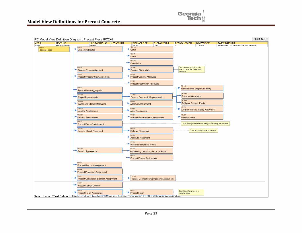
PRECAST PIECES
Model View Definitions for Precast Concrete
Could belong either to the building or the storey but not both
Could be relative to other element
Tag property of the Piece is used to store the Piece Markattribute
Could be either process or material finish
PCI-067
Precast Piece Mark
PCI-059
Approval Assignment
PCI-053
Element AttributesVBL-170
GUID
VBL-171
Name
VBL-172
Description
PCI-054
Element Type Assignment
PCI-055
Precast Property Set AssignmentPCI-056
Precast General Attributes
PCI-057
Precast Fabrication Attributes
PCI-058
System Piece Aggregation
VBL-203
Shape RepresentationICC-519
Generic Geometric Representation
PCI-066
Generic Brep Shape Geometry
VBL-013
Owner and Status Information
VBL-268
Generic AssignmentsPCI-060
Actor Assignment
VBL-258
Generic AssociationsPCI-061
Precast Piece Material AssociationVBL-265
Material Name
PCI-062
Precast Piece Containment
VBL-201
Generic Object PlacementPCI-063
Relative Placement
PCI-064
Absolute Placement
PCI-052
Placement Relative to Grid
VBL-404
Generic Aggregation
PCI-073
Precast Embed Assignment
PCI-137
Precast Connection Element Assignment
PCI-077
Precast Design Criteria
PCI-078
Precast Finish AssignmentPCI-079
Precast Finish
PCI-068
Extruded Geometry
PCI-069
Arbitrary Precast Profile
PCI-070
Arbitrary Precast Profile with Voids
PCI-074
Precast Blockout Assignment
- IFC2x4
Precast Piece
IFC Model View Definition Diagram : Precast Piece IFC2x4
PCI-001 Precast Concrete Generic Generic Draft 1 21.3.2009 Rafael Sacks, Chuck Eastman and Ivan Panushev
This document uses the official IFC Model View Definition Format version 1.1. of the IAI (www.iai-international.org).
PCI-136
Precast Connection Component Assignment
PCI-146
Precast Projection Assignment
PCI-090
Reinforcing Unit Association to Piece
Page 23
Model View Definitions for Precast Concrete
PCI-080
Precast Piece Type AttributesVBL-170
GUID
VBL-171
Name
VBL-172
DescriptionPCI-056
Precast General Attributes
PCI-057
Precast Fabrication Attributes
VBL-268
Generic Assignments
PCI-060
Actor Assignment
PCI-059
Approval Assignment
VBL-013
Owner and Status Information
PCI-066
Generic Brep Shape GeometryPCI-081
Piece Type Geometry Assignment
PCI-068
Extruded Geometry
PCI-069
Arbitrary Precast Profile
PCI-070
Arbitrary Precast Profile with Voids
000 - IFC2x4
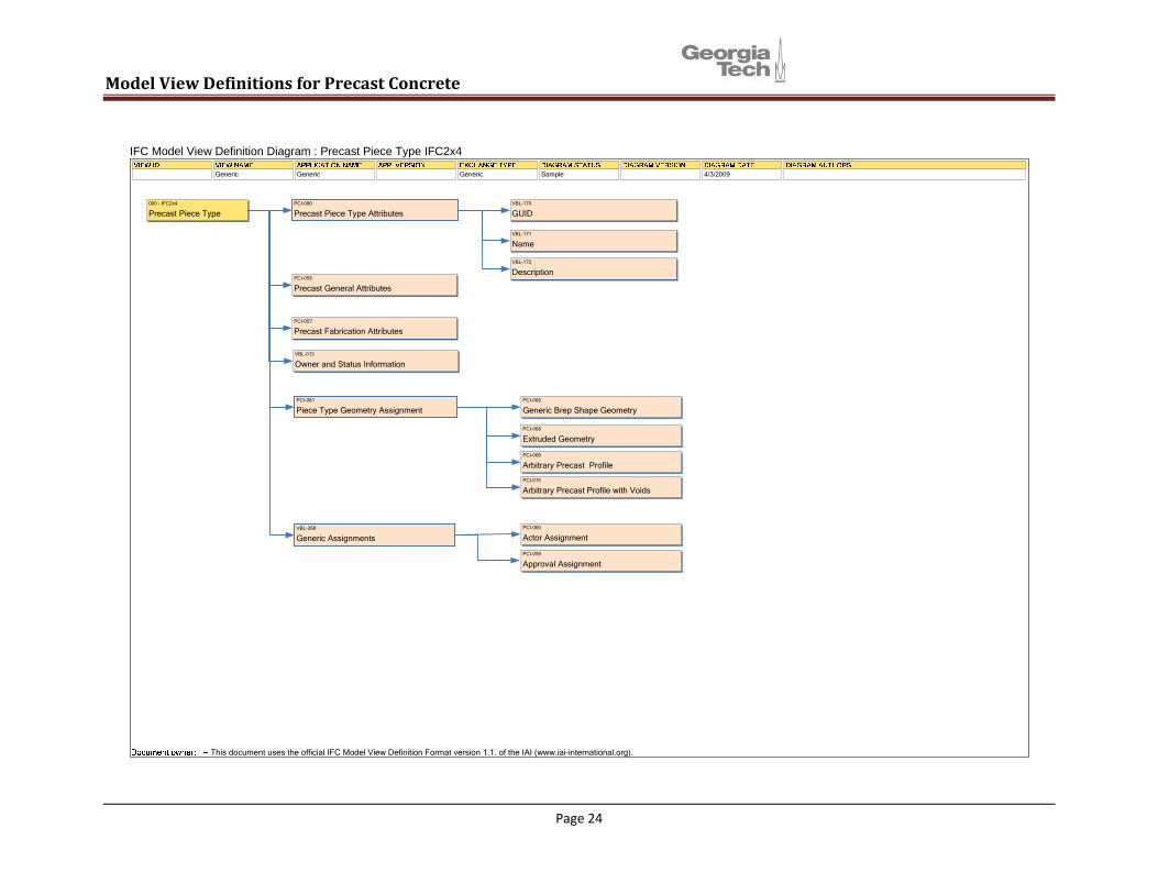
Precast Piece Type
IFC Model View Definition Diagram : Precast Piece Type IFC2x4
Generic Generic Generic Sample 4/3/2009
This document uses the official IFC Model View Definition Format version 1.1. of the IAI (www.iai-international.org).
Page 24

Model View Definitions for Precast Concrete
Could be either process or material finish
Could belong either to the building or the storey but not both
Could be relative to other element
PCI-053
Element Attributes
PCI-071
Precast Component Assignment
PCI-062
Precast Piece Containment
VBL-013
Owner and Status Information
VBL-258
Generic Associations
VBL-201
Generic Object Placement
PCI-061
Precast Piece Material AssociationVBL-265
Material Name
PCI-064
Absolute Placement
PCI-063
Relative Placement
PCI-077
Precast Design Criteria
VBL-170
GUID
VBL-171
Name
VBL-172
Description
PCI-056
Precast General Attributes
PCI-057
Precast Fabrication Attributes
PCI-072
Precast Rebar Assignment
PCI-073
Precast Embed Assignment
PCI-074
Precast Blockout Assignment
PCI-078
Precast Finish AssignmentPCI-079
Precast Finish
PCI-040
Precast Slab Aggregation
PCI-052
Placement Relative to Grid
PCI-055
Precast Property Set Assignment
PCI-066
Generic Brep Shape GeometryICC-519
Generic Geometric RepresentationVBL-203
Shape Representation
VBL-268
Generic AssignmentsPCI-060
Actor Assignment
PCI-059
Approval Assignment
- IFC2x4
Precast Slab
IFC Model View Definition Diagram : Precast Slab IFC2x4
PCI-001 Precast Concrete Generic Generic Draft 1 21.3.2009 Rafael Sacks, Chuck Eastman and Ivan Panushev
This document uses the official IFC Model View Definition Format version 1.1. of the IAI (www.iai-international.org).
Page 25
Model View Definitions for Precast Concrete
PCI-053
Element Attributes
VBL-013
Owner and Status Information
VBL-268
Generic AssignmentsPCI-060
Actor Assignment
PCI-058
System Piece Aggregation
PCI-052
Placement Relative to Grid
VBL-200
Generic Material Association
VBL-201
Generic Object PlacementPCI-064
Absolute Placement
PCI-063
Relative Placement
PCI-053
Element AttributesVBL-308
Volume
VBL-170
GUID
VBL-171
Name
VBL-172
Description
PCI-054
Element Type Assignment
PCI-059
Approval Assignment
PCI-066
Generic Brep Shape GeometryICC-519
Generic Geometric Representation
PCI-054
Element Type Assignment
VBL-203
Shape Representation
VBL-258
Generic AssociationsVBL-265
Material Name
pci - IFC2x4
Non-precast Element
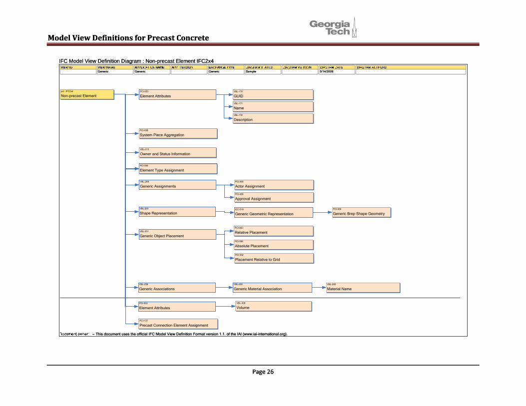
IFC Model View Definition Diagram : Non-precast Element IFC2x4
Generic Generic Generic Sample 5/14/2009
This document uses the official IFC Model View Definition Format version 1.1. of the IAI (www.iai-international.org).
PCI-137
Precast Connection Element Assignment
Model View Definitions for Precast Concrete
Page 26
Page 26
PCI-053
Element Attributes
VBL-013
Owner and Status Information
VBL-268
Generic AssignmentsPCI-060
Actor Assignment
PCI-058
System Piece Aggregation
PCI-052
Placement Relative to Grid
VBL-200
Generic Material Association
VBL-201
Generic Object PlacementPCI-064
Absolute Placement
PCI-063
Relative Placement
PCI-053
Element AttributesVBL-308
Volume
VBL-170
GUID
VBL-171
Name
VBL-172
Description
PCI-054
Element Type Assignment
PCI-059
Approval Assignment
PCI-066
Generic Brep Shape GeometryICC-519
Generic Geometric Representation
PCI-054
Element Type Assignment
VBL-203
Shape Representation
VBL-258
Generic AssociationsVBL-265
Material Name
pci - IFC2x4
Non-precast Element
IFC Model View Definition Diagram : Non-precast Element IFC2x4
Generic Generic Generic Sample 5/14/2009
This document uses the official IFC Model View Definition Format version 1.1. of the IAI (www.iai-international.org).
PCI-137
Precast Connection Element Assignment
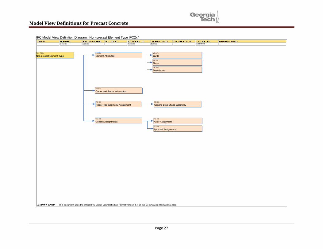
PCI-053
Element Attributes
VBL-013
Owner and Status Information
VBL-268
Generic AssignmentsPCI-060
Actor Assignment
VBL-170
GUID
VBL-171
Name
VBL-172
Description
PCI-059
Approval Assignment
PCI-066
Generic Brep Shape GeometryPCI-081
Piece Type Geometry Assignment
PCI - IFC2x4
Non-precast Element Type
IFC Model View Definition Diagram : Non-precast Element Type IFC2x4
Generic Generic Generic Sample 5/14/2009
This document uses the official IFC Model View Definition Format version 1.1. of the IAI (www.iai-international.org).
Page 27
View Definitions for Precast Concrete Model

Model View Definitions for Precast Concrete
Structural Analysis Model Correlation of building elements and their actual mechanical representations allows integrating the architectural model with the structural analysis model. This integration allows establishing the relationship between the building configuration and its corresponding structural behavior. The precast designers are not interested in the full range of structural information. So, this report focuses on the information about the structural model that is required to fully understand the design intent in a precast model. This commonly needed information is separated out from the specialized structural domain layer. For this purpose, we have referred to the work done on Structural Analysis domain by the Virtual Building Laboratory (VBL) group. A more detailed description and binding documents can be obtained from VBL under the IFC Solutions Factory (http://www.blis-project.org/IAI-MVD/). The following figure (Figure 1) shows how the integration of structural analysis domain is intended with
other domains using IFC, with Building Elements being the core concept. FIGURE 1 Integration of Structural Analysis Domain with other Domains using IfcBuildingElements as a core concept (Structural Analysis Extension for IFC, 2002) Structural Analysis Domain The inheritance structure and the main attributes and relationships defined in the structural model are depicted in the following EXPRESS G diagram (Figure 2). where is this
relation?
Page 28

Model View Definitions for Precast Concrete
FIGURE 2 EXPRESS G diagram showing the inheritance structure and main relationships and attributes defined in the structural analysis model.
Page 29

Model View Definitions for Precast Concrete
Explanation of the inheritance structure from Structural Analysis Extension for IFC, 2002 The two top-level entity classes IfcStructuralItem and IfcStructuralActivity both inherit their properties from the kernel entity class IfcProduct. In this way, general representational features such as placement, shape and other basic product data attributes are consistently provided to all structural analysis entities in the same manner as for all other tangible IFC objects. IfcStructuralItem is the root entity class for all classes representing structural objects, whereas IfcStructuralActivity is the root class for the objects representing the external impacts (loads and other actions) on these objects. IfcStructuralItem is further specialized in two main branches – structural members and structural connections which are linked through the relationship class IfcRelConnectsStructuralMember, subtype of the kernel class IfcRelConnects. In this way, the connectivity of the bearing structure is explicitly established. Structural members are further subtyped into linear and planar elements, and structural connections into point, line / curve and face / planar connections respectively. In addition to the general shape and location definitions provided through the inheritance from platform entities, these classes also have a topological representation. This is more efficient for structural analysis applications. Furthermore, connections can optionally be associated with boundary conditions that may specify node and edge restraints in terms of linear and rotational stiffness, as well as warping. As mentioned before, finite elements (which are a pure numerical abstraction) are not part of the model. IfcStructuralActivity is specialized in the two branches IfcStructuralAction and IfcStructuralReaction, allowing to differentiate between external and internal actions. External actions are further on subtyped into single (point) loads, linear loads, planar loads (pressure) and enforced displacements. They can be applied both to members and connections as well as to building elements. The relationship between the structural elements (members, connections) and the actions upon them is established through the IfcRelConnectsStructuralActivity class which is also subtyped from the IfcRelConnects class. Additionally, each action is also related to an IfcStructuralLoadGroup which provides the grouping of actions into load groups, load cases and load combinations. To facilitate re-using load definitions in other structural domain extension models, the load quantities themselves are defined as a specific “structural” resource. In a similar way, material and sectional properties are made available by importing and appropriately extending the respective IFC platform resource schemas.
Page 30
Model View Definitions for Precast Concrete
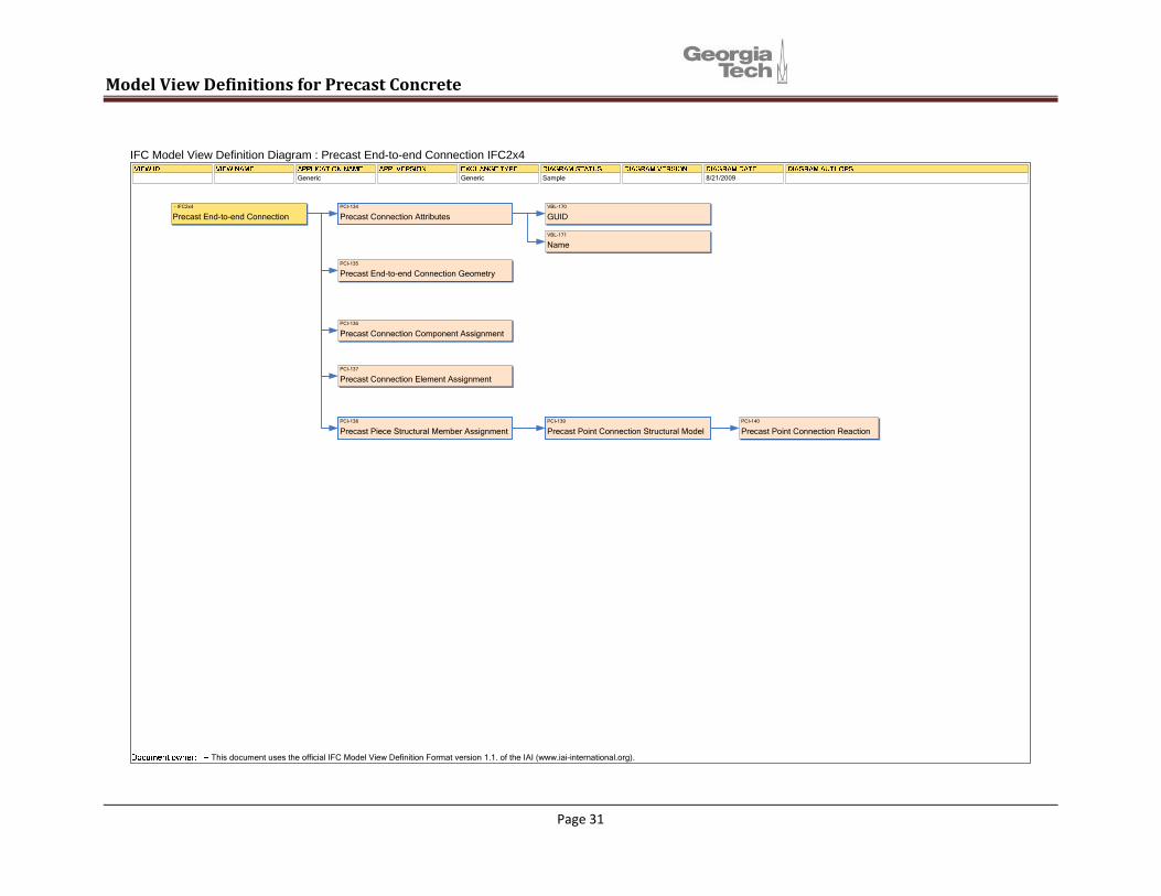
PCI-134
Precast Connection AttributesVBL-170
GUID
VBL-171
Name
PCI-136
Precast Connection Component Assignment
PCI-137
Precast Connection Element Assignment
PCI-135
Precast End-to-end Connection Geometry
PCI-138
Precast Piece Structural Member AssignmentPCI-139
Precast Point Connection Structural ModelPCI-140
Precast Point Connection Reaction
- IFC2x4
Precast End-to-end Connection
IFC Model View Definition Diagram : Precast End-to-end Connection IFC2x4
Generic Generic Sample 8/21/2009
This document uses the official IFC Model View Definition Format version 1.1. of the IAI (www.iai-international.org).
Page 31

Model View Definitions for Precast Concrete
PCI-134
Precast Connection AttributesVBL-170
GUID
VBL-171
Name
PCI-136
Precast Connection Component Assignment
PCI-137
Precast Connection Element Assignment
PCI-141
Precast End-to-edge Connection Geometry
PCI-138
Precast Piece Structural Member AssignmentPCI-140
Precast Point Connection ReactionPCI-139
Precast Point Connection Structural Model
- IFC2x4
Precast End-to-edge Connection
IFC Model View Definition Diagram : Precast End-to-edge Connection IFC2x4
Generic Generic Generic Sample 8/21/2009
This document uses the official IFC Model View Definition Format version 1.1. of the IAI (www.iai-international.org).
Page 32

Model View Definitions for Precast Concrete
PCI-134
Precast Connection AttributesVBL-170
GUID
VBL-171
Name
PCI-136
Precast Connection Component Assignment
PCI-137
Precast Connection Element Assignment
PCI-142
Precast Seam Connection Location
PCI-144
Precast Seam Connection ReactionPCI-143
Precast Seam Connection Structural ModelPCI-138
Precast Piece Structural Member Assignment
- IFC2x4
Precast Seam Connection
IFC Model View Definition Diagram : Precast Seam Connection IFC2x4
Generic Generic Generic Sample 8/21/2009
This document uses the official IFC Model View Definition Format version 1.1. of the IAI (www.iai-international.org).
Page 33

Model View Definitions for Precast Concrete
PCI-147
Precast Joint Attributes
PCI-150
Precast Joint Type Assignment
PCI-148
Precast Joint Element Assignment
PCI-149
Precast Joint Location
- IFC2x4
Precast Joint
IFC Model View Definition Diagram : Precast Joint IFC2x4
Generic Generic Generic Sample 8/21/2009
This document uses the official IFC Model View Definition Format version 1.1. of the IAI (www.iai-international.org).
Page 34

Model View Definitions for Precast Concrete
PCI-151
Precast Joint Type Attributes
PCI-152
Precast Joint Type Profiling Geometry
- IFC2x4
Precast Joint Type
IFC Model View Definition Diagram : Precast Joint Type IFC2x4
Generic Generic Generic Sample 8/21/2009
This document uses the official IFC Model View Definition Format version 1.1. of the IAI (www.iai-international.org).
Page 35
Model View Definitions for Precast Concrete
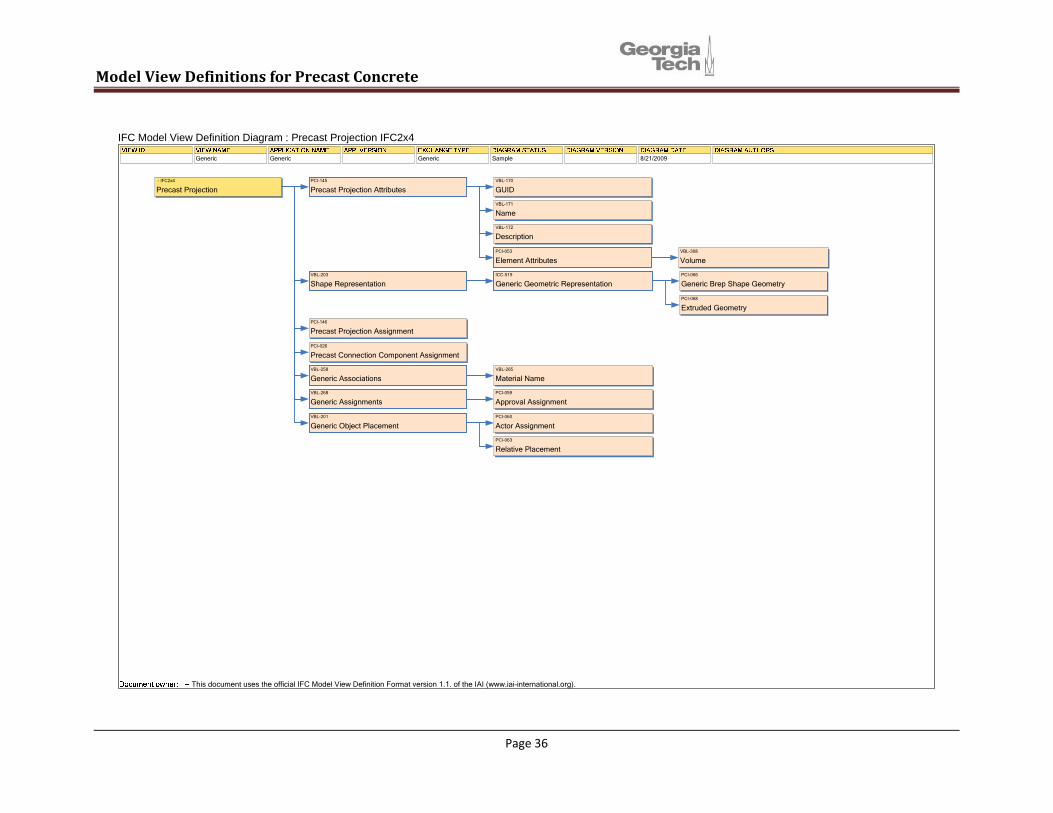
PCI-145
Precast Projection AttributesVBL-170
GUID
VBL-171
Name
VBL-172
Description
PCI-053
Element AttributesVBL-308
Volume
VBL-203
Shape RepresentationICC-519
Generic Geometric RepresentationPCI-066
Generic Brep Shape Geometry
PCI-068
Extruded Geometry
PCI-146
Precast Projection Assignment
PCI-026
Precast Connection Component Assignment
VBL-258
Generic AssociationsVBL-265
Material Name
VBL-268
Generic AssignmentsPCI-059
Approval Assignment
VBL-201
Generic Object PlacementPCI-060
Actor Assignment
PCI-063
Relative Placement
- IFC2x4
Precast Projection
IFC Model View Definition Diagram : Precast Projection IFC2x4
Generic Generic Generic Sample 8/21/2009
This document uses the official IFC Model View Definition Format version 1.1. of the IAI (www.iai-international.org).
Page 36

Model View Definitions for Precast Concrete
000 - IFC2x4
Precast Blockout
IFC Model View Definition Diagram : Precast Blockout IFC2x4
Generic Generic Generic Sample 8/21/2009
This document uses the official IFC Model View Definition Format version 1.1. of the IAI (www.iai-international.org).
PCI-083
Precast Blockout AttributesVBL-170
GUID
VBL-171
Name
VBL-172
Description
PCI-053
Element AttributesVBL-308
Volume
ICC-519
Generic Geometric Representation
PCI-085
Blockout Placement
Page 37

Model View Definitions for Precast Concrete
Plant Applied and Field Applied
Pset_ComponentProductionRequirements
PCI-100
Precast Embed AttributesVBL-170
GUID
VBL-171
Name
VBL-172
Description
PCI-053
Element AttributesVBL-307
Area
VBL-308
Volume
VBL-237
Element Quantity
PCI-091
Production AttributesPCI-092
Production Control Number
PCI-093
Surface Treatments
PCI-094
Supplier
PCI-095
Condition
PCI-096
Mechanical AttributesVBL-185
Applied Load
PCI-073
Precast Embed Assignment
PCI-098
Embed Type Assignment
PCI-101
Embed Geometry Assignment
PCI-063
Relative Placement
PCI-097
Component Property Set Assignment
VBL-268
Generic AssignmentsPCI-060
Actor Assignment
PCI-059
Approval Assignment
000 - IFC2x4
Precast Embeds
IFC Model View Definition Diagram : Precast Embeds IFC2x4
Generic Generic Generic Sample 8/21/2009
This document uses the official IFC Model View Definition Format version 1.1. of the IAI (www.iai-international.org).
Page 38

Model View Definitions for Precast Concrete
PCI-102
Precast Embed Type AttributesVBL-170
GUID
VBL-171
Name
VBL-172
Description
VBL-013
Owner and Status Information
PCI-099
Embed Type Geometry
VBL-268
Generic AssignmentsPCI-060
Actor Assignment
PCI-059
Approval Assignment
000 - IFC2x4
Precast Embed Type
IFC Model View Definition Diagram : Precast Embed Type IFC2x4
Generic Generic Generic Sample 8/21/2009
This document uses the official IFC Model View Definition Format version 1.1. of the IAI (www.iai-international.org).
Page 39

Model View Definitions for Precast Concrete
Precast Reinforcement From the interoperability point of view the goal in this effort is that the data extraction module automatically extracts the data needed for manufacturing reinforcing elements and units from the design.
In this effort, because of the binding to the IFC 2x3, the existing entities in IFC2x3 were used, which applied some limitations to modeling of all combinations of reinforcing elements in the form of reinforcing units.
In order to create the MVD documents reinforcing elements are expressed using six coneptss:
(1) Reinforcing Bar: A steel bar, with manufactured deformations in the surface
Regarding the reinforcement, the main available entity in the IFC 2x3 is the abstract entity IfcReinforcingElement which has the following subtypes: IfcReinforcingBar, IfcReinforcingMesh, IfcTendon, and IfcTendonAnchor. These entities don’t cover various reinforcing units like groups or sets of rebars and tendons (which we call “Reinforcing Element Aggregations”), engineered mesh and rebar cages. So in developing the MVD concepts for these elements, the required attributes of individual entities that build up these reinforcing units are aggregated. This imposes some limitations.
(2) Tendon: Pretensioned, Usually from 7-wire strands
(3) Standard Mesh: A series of longitudinal and transverse wires or bars of various gauges, arranged at right angles and welded together
On the other hand, the type and instance distinction has not been made explicit in the IFC 2x3 reinforcement-related entities. Therefore, the MVD concepts are defined in a way that users can choose to apply this distinction. For instance, they can define the geometry and shape representation information once for any rebar type and then assign it to the number of instances of that type in different aggregations. This way the users’ approach to the work determines using type and instance distinction.
(4) Engineered Mesh: To create custom designed mesh with different spacing and size among the longitudinal and transverse bars, the possibility of bending the bars, having custom peripheral shapes, and the project-specific sheet size
(5) Reinforcing Element Aggregation: Various arrays of tendons, rebar, and standard meshes Given the lack of development of the type instance formalisms in IFC
2x3, there is also no provision in the MVD for rebar or tendon ‘patterns’, which are typical groupings of rebars or tendons that a plant might offer as a standard library. It is therefore not possible to carry standard patterns, applied to concrete sections, by using of library references alone.
(6) Rebar Cage: Three dimensional assemblies of longitudinal and transverse bars. A rebar cage is considered to be a higher level assembly of rebars than a reinforcing element aggregation.
Page 40

Model View Definitions for Precast Concrete
Hierarchy of Reinforcing Elements and Units
Page 41

Model View Definitions for Precast Concrete
PCI-117
Reinforcing Bar Attributes
VBL-201
Generic Object Placement
VBL-170
GUID
VBL-171
Name
VBL-172
Description
VBL-013
Owner and Status Information
PCI-063
Relative Placement
PCI-086
Reinforcing Element Property Set AssignmentPCI-111
Rebar Bending Attributes
VBL-404
Generic Aggregation
PCI-090
Reinforcing Unit Association to Piece
PCI-113
Rebar Association to Engineered Mesh
PCI-110
Coating Material Properties
PCI-114
Rebar Association to Standard Mesh
VBL-200
Generic Material AssociationPCI-109
Steel Material Properties
PCI-087
Generic Shape RepresentationPCI-088
Rebar Extruded Shape Geometry
PCI-064
Absolute Placement
PCI-104
Reinforcing Element Association to Reinforcing Element Aggregation
000 - IFC2x4
Rebar
IFC Model View Definition Diagram : Rebar IFC2x4
Generic Generic Generic Sample 4/13/2009
This document uses the official IFC Model View Definition Format version 1.1. of the IAI (www.iai-international.org).
Page 42

Model View Definitions for Precast Concrete
Based on the debonding method the material is different. The main methods include: Encapsulating the strands with sheaths, and applying a bond breaker.
PCI-086
Reinforcing Element Property Set Assignment
PCI-090
Reinforcing Unit Association to Piece
PCI-104
Reinforcing Element Association to Reinforcing Element Aggregation
PCI-127
Tendon Debonding Relative Placement
PCI-129
Tendon Debonding Material
PCI-128
Tendon Debonding LengthPCI-112
Tendon Debonding Attributes
PCI-122
Tendon Tension Force
PCI-125
Tendon Min Curvature Radius
PCI-124
Tendon Friction Coefficient
PCI-123
Tendon Prestress
PCI-126
Tendon Anchorage Slip
VBL-170
GUID
VBL-171
Name
VBL-172
Description
VBL-201
Generic Object Placement
VBL-013
Owner and Status Information
PCI-063
Relative Placement
PCI-110
Coating Material Properties
VBL-200
Generic Material Association
PCI-109
Steel Material Properties
PCI-087
Generic Shape RepresentationPCI-089
Tendon Extruded Shape Geometry
PCI-064
Absolute Placement
PCI-118
Tendon Attributes
000 - IFC2x4
Tendon
IFC Model View Definition Diagram : Tendon IFC2x4
Generic Generic Sample 8/25/2009
This document uses the official IFC Model View Definition Format version 1.1. of the IAI (www.iai-international.org).
VBL-404
Generic Aggregation
These are properties of the IfcTendon; they are all defined in the Tendon Attributes concept, PCI-118
Page 43

Model View Definitions for Precast Concrete
PCI-133
Reinforcing Mesh Attributes
VBL-201
Generic Object Placement
VBL-170
GUID
VBL-171
Name
VBL-172
Description
VBL-013
Owner and Status Information
PCI-063
Relative Placement
PCI-110
Coating Material Properties
VBL-200
Generic Material AssociationPCI-109
Steel Material Properties
PCI-087
Generic Shape RepresentationPCI-088
Rebar Extruded Shape Geometry
PCI-064
Absolute Placement
000 - IFC2x4
Standard Mesh
IFC Model View Definition Diagram : Standard Mesh IFC2x4
Generic Generic Sample 8/25/2009
This document uses the official IFC Model View Definition Format version 1.1. of the IAI (www.iai-international.org).
PCI-090
Reinforcing Unit Association to Piece
PCI-104
Reinforcing Element Association to Reinforcing Element Aggregation
VBL-404
Generic Aggregation
Page 44

Model View Definitions for Precast Concrete
PCI-107
Longitudinal Bar Attributes
PCI-108
Transverse Bar Attributes
VBL-201
Generic Object PlacementPCI-063
Relative Placement
PCI-120
Reinforcing Unit Attributes
VBL-201
Generic Object Placement
VBL-170
GUID
VBL-171
Name
VBL-172
DescriptionVBL-013
Owner and Status Information
PCI-063
Relative Placement
VBL-200
Generic Material AssociationPCI-109
Steel Material Properties
PCI-087
Generic Shape RepresentationPCI-088
Rebar Extruded Shape Geometry
PCI-064
Absolute Placement
PCI-086
Reinforcing Element Property Set AssignmentPCI-111
Rebar Bending Attributes
VBL-201
Generic Object PlacementPCI-063
Relative Placement
VBL-200
Generic Material AssociationPCI-109
Steel Material Properties
PCI-087
Generic Shape RepresentationPCI-088
Rebar Extruded Shape Geometry
PCI-086
Reinforcing Element Property Set AssignmentPCI-111
Rebar Bending Attributes
PCI-130
Mesh Length
PCI-131
Mesh Width
PCI-086
Reinforcing Element Property Set Assignment
000 - IFC2x4
Engineered Mesh
IFC Model View Definition Diagram : Engineered Mesh IFC2x4
Generic Generic Sample 8/25/2009
This document uses the official IFC Model View Definition Format version 1.1. of the IAI (www.iai-international.org).
PCI-110
Coating Material Properties
PCI-110
Coating Material Properties
PCI-090
Reinforcing Unit Association to Piece
PCI-104
Reinforcing Element Association to Reinforcing Element Aggregation
VBL-404
Generic Aggregation
Page 45

Model View Definitions for Precast Concrete
PCI-120
Reinforcing Unit Attributes
VBL-201
Generic Object Placement
VBL-170
GUID
VBL-171
Name
VBL-172
Description
VBL-013
Owner and Status Information
PCI-063
Relative Placement
PCI-064
Absolute Placement
PCI-090
Reinforcing Unit Association to Piece
PCI-103
Reinforcing Element Aggregation Association to Rebar Cage
000 - IFC2x4
Reinforcement Element Aggregation
IFC Model View Definition Diagram : Reinforcement Element Aggregation IFC2x4
Generic Generic Sample 8/26/2009
This document uses the official IFC Model View Definition Format version 1.1. of the IAI (www.iai-international.org).
Represents both a) sets of bars (e.g. 5#6 bars in the bottom of a beam) and,b) tendon patterns
VBL-404
Generic Aggregation
Page 46
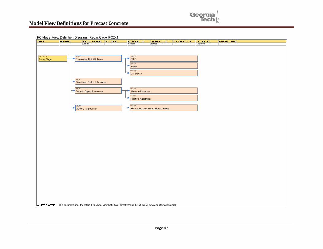
PCI-120
Reinforcing Unit AttributesVBL-170
GUID
VBL-171
Name
VBL-172
Description
VBL-013
Owner and Status Information
VBL-201
Generic Object PlacementPCI-064
Absolute Placement
PCI-063
Relative Placement
PCI-090
Reinforcing Unit Association to Piece
000 - IFC2x4
Rebar Cage
IFC Model View Definition Diagram : Rebar Cage IFC2x4
Generic Generic Sample 8/26/2009
This document uses the official IFC Model View Definition Format version 1.1. of the IAI (www.iai-international.org).
VBL-404
Generic Aggregation
Page 47
View Definitions for Precast Concrete Model

Model View Definitions for Precast Concrete
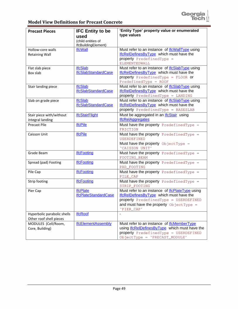
Appendix A: Building Entity Subtypes for Precast Pieces and Precast Piece Types The table below defines the ways in which all precast pieces are to be modeled using IFC 2x4. The identities of specific precast piece types are set using a combination of the IFC entity type and the value of the PredefinedType property of the Building Element Type entity associated with the Building Element itself.
IFC Entity to be used
‘Entity Type’ property value or enumerated type values
Precast Pieces
(child entities of IfcBuildingElement) IfcBeam Must refer to an instance of IfcBeamTypeBEAMS
Box Beam Rectangular Beam Transfer Beam Bridge Segment
using IfcBeamStandardCase IfcRelDefinesByType which must have the
property PredefinedType = BEAM
IfcBeam Must refer to an instance of IfcBeamTypeHollow Core plank Double Tee
using IfcBeamStandardCase IfcRelDefinesByType which must have the
property PredefinedType = SLAB_PART (IFC 2x4 Beta) PredefinedType = JOIST (IFC 2x3)
IfcBeam Must refer to an instance of IfcBeamTypeInverted Tee Beam L Beam
using IfcBeamStandardCase IfcRelDefinesByType which must have the
property PredefinedType = SLAB_SUPPORT_BEAM (IFC 2x4 Beta) PredefinedType = T_BEAM (IFC 2x3)
IfcBeam Must refer to an instance of IfcBeamTypeStructural Spandrels (Pocket, Ledge, Button Haunch, Deep Beams)
using IfcBeamStandardCase IfcRelDefinesByType which must have the
property PredefinedType = SPANDREL (IFC 2x4 Beta)
IfcCovering Must refer to an instance of IfcCoveringTypeDECORATIVE PIECES Decorative Panel Column Cover Mullions Head Sill Cap (pieces with no structural function)
using IfcRelDefinesByType which must have the property PredefinedType = CLADDING Must be related to a child entity of IfcBuildingElement using IfcRelCoversBldgElements
IfcColumn - Column Drilled Pier
IfcWall Must refer to an instance of IfcWallTypeCore wall Pilasters Insulated wall pieces Stem Wall
using IfcRelDefinesByType which must have the property PredefinedType = STANDARD
IfcWall Must refer to an instance of IfcWallTypeLite‐wall Shear wall K‐Frames Pilasters
using IfcRelDefinesByType which must have the property PredefinedType = SHEAR
Page 48
Model View Definitions for Precast Concrete
IFC Entity to be used
‘Entity Type’ property value or enumerated type values
Precast Pieces
(child entities of IfcBuildingElement) IfcWall Must refer to an instance of IfcWallTypeHollow‐core walls
Retaining Wall using
IfcRelDefinesByType which must have the property PredefinedType = ELEMENTEDWALL
IfcSlab Must refer to an instance of IfcSlabTypeFlat slab piece Box slab
using IfcSlabStandardCase IfcRelDefinesByType which must have the
property PredefinedType = FLOOR or PredefinedType = ROOF
IfcSlab Must refer to an instance of IfcSlabTypeStair landing piece using IfcSlabStandardCase IfcRelDefinesByType which must have the
property PredefinedType = LANDING IfcSlab Must refer to an instance of IfcSlabTypeSlab on grade piece
using IfcSlabStandardCase IfcRelDefinesByType which must have the
property PredefinedType = BASESLAB Stair piece with/without integral landing
IfcStairFlight Must be aggregated in an IfcStair using IfcRelAggregates
IfcPile Must have the property PredefinedType = FRICTION
Precast Pile
IfcPile Must have the property PredefinedType = USERDEFINED
Caisson Unit
Must have the property ObjectType = ‘CAISSON UNIT’
IfcFooting Must have the property PredefinedType = FOOTING_BEAM
Grade Beam
IfcFooting Must have the property PredefinedType = PAD_FOOTING
Spread (pad) Footing
IfcFooting Must have the property PredefinedType = PILE_CAP
Pile Cap
IfcFooting Must have the property PredefinedType = STRIP_FOOTING
Strip footing
IfcPlate Must refer to an instance of IfcPlateTypePier Cap using IfcPlateStandardCase IfcRelDefinesByType which must have the
property PredefinedType = USERDEFINED and must have the property ObjectType = ‘PIER_CAP’
IfcRoof - Hyperbolic parabolic shells Other roof shell pieces
IfcElementAssembly Must refer to an instance of IfcMemberTypeMODULES (Cell/Room, Core, Building) using IfcRelDefinesByType which must have the
property PredefinedType = USERDEFINED ObjectType = ‘PRECAST_MODULE’
Page 49
Model View Definitions for Precast Concrete
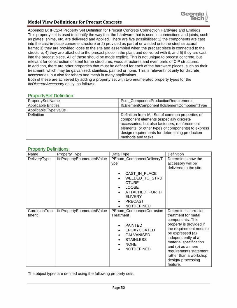
Appendix B: IFC2x4 Property Set Definition for Precast Concrete Connection Hardware and Embeds This property set is used to identify the way that the hardware that is used in connections and joints, such as plates, shims, etc. are delivered and applied. There are five possibilities: 1) the components are cast into the cast-in-place concrete structure or 2) provided as part of or welded onto the steel structural frame; 3) they are provided loose to the site and assembled when the precast piece is connected to the structure; 4) they are attached to the precast piece in the plant and delivered with it; and 5) they are cast into the precast piece. All of these should be made explicit. This is not unique to precast concrete, but relevant for construction of steel frame structures, wood structures and even parts of CIP structures. In addition, there are other properties that must be defined for each of the hardware pieces, such as their treatment, which may be galvanized, stainless, painted or none. This is relevant not only for discrete accessories, but also for rebars and mesh in many applications. Both of these are achieved by adding a property set with two enumerated property types for the IfcDiscreteAccessory entity, as follows:
PropertySet Definition: PropertySet Name Pset_ComponentProductionRequirements Applicable Entities IfcElementComponent IfcElementComponentType Applicable Type value Definition Definition from IAI: Set of common properties of
component elements (especially discrete accessories, but also fasteners, reinforcement elements, or other types of components) to express design requirements for determining production methods and tasks.
Property Definitions: Name Property Type Data Type Definition DeliveryType IfcPropertyEnumeratedValue PEnum_ComponentDeliveryT
ype Determines how the accessory will be delivered to the site.
• CAST_IN_PLACE • WELDED_TO_STRU
CTURE • LOOSE • ATTACHED_FOR_D
ELIVERY • PRECAST • NOTDEFINED
CorrosionTreatment
IfcPropertyEnumeratedValue PEnum_ComponentCorrosionTreatment
Determines corrosion treatment for metal components. This property is provided if the requirement nees to be expressed (a) independently of a material specification and (b) as a mere requirements statement rather than a workshop design/ processing feature.
• PAINTED • EPOXYCOATED • GALVANISED • STAINLESS • NONE • NOTDEFINED
The object types are defined using the following property sets.
Page 50
Model View Definitions for Precast Concrete
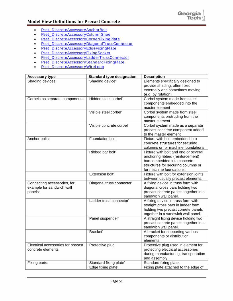
• Pset_DiscreteAccessoryAnchorBolt • Pset_DiscreteAccessoryColumnShoe • Pset_DiscreteAccessoryCornerFixingPlate • Pset_DiscreteAccessoryDiagonalTrussConnector • Pset_DiscreteAccessoryEdgeFixingPlate • Pset_DiscreteAccessoryFixingSocket • Pset_DiscreteAccessoryLadderTrussConnector • Pset_DiscreteAccessoryStandardFixingPlate • Pset_DiscreteAccessoryWireLoop
Accessory type Standard type designation Description Shading devices: 'Shading device' Elements specifically designed to
provide shading, often fixed externally and sometimes moving (e.g. by rotation)
Corbels as separate components: 'Hidden steel corbel' Corbel system made from steel components embedded into the master element
'Visible steel corbel' Corbel system made from steel components protruding from the master element
'Visible concrete corbel' Corbel system made as a separate precast concrete component added to the master element
Anchor bolts: 'Foundation bolt' Fixture with bolt embedded into concrete structures for securing columns or for machine foundations
'Ribbed bar bolt' Fixture with bolt and one or several anchoring ribbed (reinforcement) bars embedded into concrete structures for securing columns or for machine foundations.
'Extension bolt' Fixture with bolt for extension joints between usually precast elements.
Connecting accessories, for example for sandwich wall panels:
'Diagonal truss connector' A fixing device in truss form with diagonal cross bars holding two precast conrete panels together in a sandwich wall panel.
'Ladder truss connector' A fixing device in truss form with straight cross bars in ladder form holding two precast conrete panels together in a sandwich wall panel.
'Panel suspender' A straight fixing device holding two precast conrete panels together in a sandwich wall panel.
'Bracket' A bracket for supporting various components or distribution elements.
Electrical accessories for precast concrete elements:
'Protective plug' Protective plug used in element for protecting electrical accessories during manufacturing, transportation and assembly.
Fixing parts: 'Standard fixing plate' Standard fixing plate. 'Edge fixing plate' Fixing plate attached to the edge of
Page 51

Model View Definitions for Precast Concrete
Accessory type Standard type designation Description an element.
'Corner fixing plate' Fixing plate attached to the corner of an element.
'Slab fixing plate' Fixing plate for slabs. 'Balcony hinge' Accessory supporting and fixing
balconies. 'Frame shoe' Fixing shoe for frames. 'Thermo frame' Thermo frame. 'Column shoe' Fixing shoe for columns. 'Wall shoe' Fixing shoe for walls. 'Fixing socket' Fixing socket. Joint accessories: 'Neoprene bearing plate' Rubber plate used as a bearing in,
for example, joints between column corbels and beams.
'Working joint reinforcement' Reinforcement accessory used in working joints.
'Expansion joint reinforcement'
Reinforcement accessory used in expansion joints.
'Ribbed steel bar extension' Extension accessory made of a ribbed (reinforcement) bar used in joints.
'Steel pin bolt' Pin bolt used to join together, for example, columns and beams.
'Concrete dowel' Dowel pin used in joints. 'Concrete groove' A groove made in a joint. 'Steel plate' A steel plate used as an accessory
in a joint. 'Wire loop' A joint connector accessory made
from a wire loop. 'Steel loop' A joint connector accessory made
from a steel bar loop. 'Sealing strip' A strip sealing the joint. 'Sealing compound' Sealing compound protecting and
sealing the joint. Lifting accessories: 'Wire lifting hook' A lifting aid in the form of a wire
loop. 'Steel lifting hook' A lifting aid in the form of a steel bar
loop. 'Lifting socket' A lifting aid in the form of a socket. 'Steel lifting anchor' A lifting aid in the form of a steel
lifting anchor. 'Lifting hole' A lifting aid in the form of a hole. Accessories mainly used in the building services domain:
'Antivibration' An isolating device to prevent other elements to be effected by vibrations.
'Drop rod' A length of material providing a hanging support to a bracket. Note that a drop rod is considered to include nuts and washers required for securing.
'Duct foot' A base support used to receive a vertical pipe (BS6100 330 3309 - duct foot).
Page 52
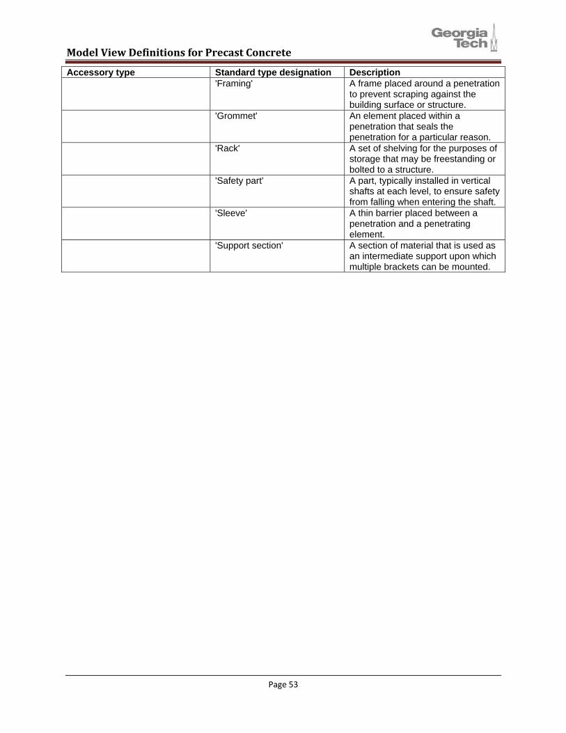
Model View Definitions for Precast Concrete
Accessory type Standard type designation Description 'Framing' A frame placed around a penetration
to prevent scraping against the building surface or structure.
'Grommet' An element placed within a penetration that seals the penetration for a particular reason.
'Rack' A set of shelving for the purposes of storage that may be freestanding or bolted to a structure.
'Safety part' A part, typically installed in vertical shafts at each level, to ensure safety from falling when entering the shaft.
'Sleeve' A thin barrier placed between a penetration and a penetrating element.
'Support section' A section of material that is used as an intermediate support upon which multiple brackets can be mounted.
Page 53