model vc-2 vacuum curettage unit isection i introduction - the berkeley bio-engineering vc-2 has...
TRANSCRIPT

MODEL VC-2
VACUUM CURETTAGE U N I T
i I I i
. I
I I I I
1 I BSE Yo. X17-52953 Revised: July 1978
..
OPERATION & S E R V I C E MANUAL
BERKELEY BIO-ENGINEERING
Copyright O 1977 by Berkeley Bio-Engineering
I


TABLE OF CONTENTS
Page
- ................................................ I . INTRODUCTION 1
. .................................... I I PRELIMINARY INSTRUCTIONS 2
......................................... . 111 GENERAL DESCRIPTION 3 ............................................ . 1 In t roduc t ion 3 ........................................... . 2 Spec i f ica t ions 5 .......................................... . 3 Motor and Pump 6 .................................................. . 4 Vacuum 6
................................................... OPERATION 9
....................................... (1) Power Connection 9 ........................................... (2) Power Switch 9 ........................................... (3) Vacuum Check 9
............................................. TROUBLESHOOTING 11
I . Overloads ............................................... 11 . ............. 2 Motor Functions/Inadequate Vacuum/No Vacuum 11 .................................... . 3 Coupling Replacement 15 ....................................... . 4 Motor Mal funct ion 16 ................................ . 5 Switch Cable Replacement 18
........................................... V I . CARE AND CLEANING 21
............................. . V I I PARTS LISTS & ASSEMBLY DRAWINGS 22
............................. V I I I . REPLACEMENT PARTS & ACCESSORIES 39


L I S T OF FIGURES
Number
. ................................*.................... 1 MODEL VC-2 ...
lsl- ............................................ . 2 PUMP/MOTOR ASSEMBLY
........................................... . 3 ELEMENTS OF THE VC-2
....................................... . 4 SWITCH CABLE REPLACEMENT
............................................ . 5 VC-2 F I N A L ASSEMBLY
.................................................. . 6 BASE ASSEMBLY
7 . PUMP ASSEMBLY ...................................................
Page
4
7
12
19
25
27
29
8 . MOTOR & SWITCH ELECTRICAL P ICTORIAL ............................ 31
.............................................. . 9 TOP COVER ASSEMBLY 33
........................................... . 1 0 SAFETY TRAP ASSEMBLY 35
............................................... . 11 CABINET ASSEMBLY 37

SECTION I
INTRODUCTION
- The Berkeley Bio-Engineering VC-2 has been specially designed t o safely
and rapidly evacuate the products of the f i r s t trimester of pregnancy. As
w i t h a l l Berkeley VC systems, the VC-2 enables a s ignif icant reduction i n
blood 1 oss, myometrial damage, and anesthesia requirement.
The upper compartment contains ample space f o r storing the disposable VC
accessories (col 1 ec t i on tubes, swivel hand1 es , ~acurettes@*). The 1 ower
compartment contains the high-capacity pump and i t s explosion-proof motor
(NEMA Rating: Group 1, Class C ) . The other external features - the col-
lection bot t le holders, vacuum gauge, vacuum adjust knob, and power knob -
a r e contained on the top panel of the u n i t . The top panel and inner shelf
are s ta in less s t e e l , and the cabinet has a smooth, baked enamel finish.
Rubber casters permit easy maneuverability of the en t i re u n i t .
Careful consideration of the important points i n routine operation and
maintenance will assure years of trouble-free performance from your VC-2.
*"Vacurettel! i s the registered trademark of disposable vacuum aspiration curet tes manufactured and sold excl usi vely by Berkeley Bio-Engineeri ng .

SECTION I1
PRELIMINARY INSTRUCTIONS
Refer t o top view on Figure 3 (Page 12). Assemble the VC-2 as follows:
- (1) Open the shipping carton and remove the contents carefully, a s
some of the components are fragi le . The bottles and t u b i n g
are shipped i n the upper compartment.
(2) Mount the two bottle holders to the top panel. Insert the
mounting screw - welded t o the bottom of each bot t le holder - into the top panel. Then secure the screws underneath the
panel w i t h the wing nuts and lockwashers provided.
(3) Insert the collection bottles into the bottle holders on the
top panel of the u n i t .
(4) Connect the t ub ing between the first and second collection
bottle and between the second collection bottle and the i n l e t
f i t t i n g on the top panel.
(5) Select the appropriate Vacurettea and connect i t to the col-
lection tubing handle assembly. Then attach the handle as-
sembly t o the in le t port on the f i r s t collection bottle.
(6) The VC-2 i s now ready t o operate. Observe that the l ine
voltage rating shown on the back panel corresponds t o avail-
able power, e i ther 11 5 Vac, 50/60 Hz, or 230 Vac, 50/60 Hz.

SECTION I11
GENERAL DESCRIPTION
" 1. Introduction
Refer to Figure 1 (Page 4 ) fo r ident if icat ion of the VC-2 controls
and assembl ies .
Vacuum Gauge - Indicates the amount of vacuum being generated
i n centimeters of mercury (crnHg).
Vacuum A d j u s t Knob - Controls the level of vacuum desired.
Collection Bottles - Collect aspirated t issue from the collec-
tion tubing.
Power Knob -Pull to t u r n power "ON," push t o t u r n power "OFF."
Storage Compartment Door Latch - Push latch and pull out t o
open the storage compartment.
m PumplMotor Compartment Door Latch - Push latch and p u l l out t o
open the pump/motor cornpartmen t .
NOTE: The power cord can be stored by winding i t around the cord wrap
on the back panel of the u n i t .

VACUUM
VACUUM GAUGE 7
COLLECTION B O l l L E S
, .-. .. STORAGE COMPAR'iMENT DOOR LATCH
FIGURE 1, MODEL VC-2

2. Specifications
Operating Voltage
115/230 Vac, - + lo%, 50/60 Hz
Power Consumpti on
Leakage Current
Less than 100 p A max
Ground Resistance
Less than 0.10 ohms case t o ground connection
Motor Horsepower Rating
One-Quarter Horsepower
Power Cord
18GA/3 conductor, Type SO, 10 ft. (304.80 cm) i n length, Woodhead
85447 plug
Dimensions
Length: 28 i n . (71.12 cm)
Width: 19 i n . (48.26 cm) . .
-Height: 42 i n . (106.68 cm)
Weight
125 lbs. (56.70 kg)
Shipping Weight
156 Ibs. (70.80 kg)
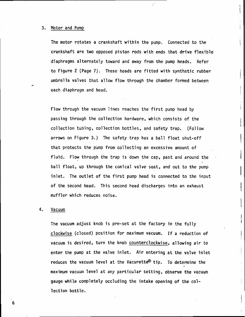
3. Motor and Pump
The motor r o t a t e s a crankshaf t w i t h i n the pump. Connected t o t h e
crankshaf t a re two opposed p i s t o n rods w i t h ends t h a t d r i v e f l e x i b l e
diaphragms a l t e r n a t e l y toward and away from t h e pump heads. Refer
t o F igure 2 (Page 7) . These heads are f i t t e d w i t h syn the t i c rubber
umbrella valves t h a t a l l ow f low through the chamber formed between
each diaphragm and head.
Flow through t h e vacuum l i n e s reaches t h e f i r s t pump head by
passing through t h e c o l l e c t i o n hardware, which cons is ts o f t h e
c o l l e c t i o n tubing, c o l l e c t i o n b o t t l e s , and sa fe ty t rap . (Fol low
arrows on Figure 3.) The sa fe ty t r a p has a b a l l f l o a t s h u t - o f f
t h a t p ro tec ts t h e pump from c o l l e c t i n g an excessive amount o f
f l u i d . Flow through the t r a p i s down the cap, pas t and around t h e .
b a l l f l o a t , up through the con ica l va lve seat, and ou t t o the pump
i n l e t . The o u t l e t o f the f i r s t pump head i s connected t o the i n p u t
o f the second head. This second head discharges i n t o an exhaust
m u f f l e r which reduces noise.
4. Vacuum
The vacuum a d j u s t knob i s pre-set a t t h e f a c t o r y i n t h e f u l l y
clockwise (c losed) p o s i t i o n f o r maximum vacuum. If a reduct ion o f
vacuum i s desired, t u r n the knob counterclockwise, a l l ow ing a i r t o
en ter the pump a t t h e valve i n l e t . A i r en te r ing a t t he valve i n l e t
reduces the vacuum l e v e l a t t h e ~ a c u r e t t g t i p . To determine the
maximum vacuum l e v e l a t any p a r t i c u l a r se t t i ng , observe t h e vacuum
gauge wh i le completely occluding t h e i n t a k e opening o f t h e co l -
l e c t i o n b o t t l e .

MUFFLER
SECOND PUMP HEAD
FIRST PUMP HERD
FIGURE 2. PUMP/MOTOR ASSEMBLY

Design considerations l imit the lower vacuum sett ings. The maximum
attainable vacuum will be approximately 73 crnHg ( the green zone on
the vacuum gauge) a t sea level, when the vacuum adjust knob i s
turned fu l ly clockwise (closed). There i s a reduction of maximum
vacuum by 2.6 cmHg per 1000 f e e t (8.5 mnHg per 100 meters) of
elevation above sea level.
Vacuum-tight connections are assured when the tapered f i t t i n g s and
internal conductive rubber O-ring seals are properly connected and
maintained. Proper sealing will maintain a consistent level of
vacuum throughout the ent i re unit.

SECTION IV
OPERATION
#-
To assure proper operation of the VC-2, follow the s teps below:
(1 ) Power Connection
Attach t he power cord t o an appropriate, grounded power re-
ceptacle. The correct voltage, frequency, and current drain
wi l l be found on the e l e c t r i c a l r a t ing p la te a t the center r e a r
of t he u n i t . The VC-2 i s used on 115 Vac, 50160 Hz, in the U.S.
In overseas models, the voltage ra t ing i s e i t h e r 115 Vac, 50/60
Hz, o r 230 Vac, 50160 Hz.
( 2 ) POWER Knob
The POWER knob is located on the top panel of the u n i t . Pull
this knob "ON" t o a c t i va t e the motor f o r vacuum. Do not t u r n
the power on when the vacuum gauge indicates the col lec t ion sys-
tem has residual vacuum, because the u n i t wil l not s t a r t . To e -
bl eed o f f the vacuumiturn -the vacuum ad jus t knob countercl oc k-
wise.
( 3 ) Vacuum Check 0 Continuous vacuum is supplied t o the Vacurette t i p while the
pump and motor a r e i n operation, unless otherwise controlled
b.v t he s l i p r ing on the rota t ing handle of the col lec t ion tub-
i n g assembly. This s l i p ring is used t o open and c lose the

o r i f i c e on the handle. The o r i f i c e i s l e f t open when the
operator does not want vacuum a t the ~acu re t t e " t i p .
To determine the maximum vacuum t h a t i s being generated, place
a f i n g e r over the tubing i n l e t a t the co l l ec t i on bo t t l e . Con-
t i nue t o occlude the opening, and observe the vacuum gauge
u n t i l i t s tab i l i zes . This vacuum l eve l i s the maximum vacuum
leve l a t the p a r t i c u l a r se t t i ng o f the vacuum adjust knob.
Turn the vacuum ad jus t knob counterclockwise t o decrease maxi- . . .
mum vacuum and clockwise t o increase maximum vacuum. Repeat . - . . .
t h i s checking procedure a f t e r each knob adjustment.

SECTION V
TROUBLESHOOTING
1. Overloads
The e l ec t r i c motor contains an internal thermal overload mechanism,
which provides protection against overheating of the motor. If the
motor s t a r t s t o overheat, the overload protector stops the action of
the motor and the pump. Whenever an overload occurs, the operator
should t u r n power off , open the lower compartment, and allow suff i -
c ient time for the motor t o cool. The motor will s t a r t up again
when the ambient temperature has been reduced suff icient ly .
2. Motor Functions/Inadequate Vacuum/No Vacuum
Turn the power "ON." Refer t o the following troubleshooting check-
out procedure and Figure 3 (Page 12) i f :
e the motor functions but the vacuum gauge indicates that vacuum
i s below the appropriate level (the green zone on the vacuum
gauge).
the vacuum gauge gives an appropriate vacuum reading b u t there
i s apparently inadequate o r no vacuum.
These symptoms indicate e i ther a leak or blockage w i t h i n the collec-
t ion system. The l e t t e r s i n the fol lowing troubleshootjng procedure
denote specific connection points on Figure 3.

- VACUUM ADJUST KNOB
VACUUM GAUGE -- COCLECTIW BOTnES
POWER KNOB-
STORAGE CQCIPARTHEHT
SWITCHBOX-.
-PUW/W)TOR C W A R X N T
kp -
a -
FIGURE 3. ELEMENTS OF THE VC-2

(1) Verify tha t the lack of vacuum is not caused by improper vacuum
adjust knob sett ing. Turn the vacuum adjust knob clockwise
u n t i l i t stops (A). Read the vacuum gauge and f inger check*
suction a t the ~acure t te" t i p . I f the vacuum level i s not
adequate, go on t o Step 2.
(2) Examine the s l i p r i n g on the Vacurette handle (B) . I f the ring
i s worn o r defective, the handle should be replaced or repaired.
Read the vacuum gauge and finger check suction a t the Vacurette
t i p . I f the vacuum level is not appropriate, go on t o Step 3.
(3) The f i t t i n g between the Vacurette handle and the tubing should
be checked for cracks and leaks (C). I f no problem seems to
ex i s t , disconnect the Vacurette tubing assembly a t the in l e t to
the f i r s t collection bot t le (D). Examine the O-ring on the
bot t le top for wear. If i t i s defective, replace i t . Read the
vacuum gauge and finger check suction a t the bot t le opening. If
the vacuum level is not appropriate, go on to Step 4.
(4) Repeat Step 3 t o check out second collection bottle. I f the
vacuum level is s t i l l not appropriate, go on to Step 5.
(5) The leak or block can be identified and corrected by examining.
each section of the collection system between the second col-
lection bot t le and the pump. Disconnect collection tubing a t
the i n l e t f i t t i n g on the top panel of the u n i t ( E ) . Finger
*Momentarily occluding the vacuum l ine or f i t t i n g w i t h a finger to e s t i - mate the level of vacuum available a t tha t particular point.

check t h i s f i t t i n g and read the vacuum gauge. I f the vacuum is
not a t maximum level, go on to Step 6. ,:
(6) Open the upper and lower compartments of the u n i t . Check the
continuity of the vacuum l ine between the second collection
bott le and the pump. Inspect fo r k i n k s , leaks, and obstructions
along the tubing, and a t each f i t t ing . Examine carefully the - safety t rap and its f l oa t ball (F). Liquid will col lec t i n the
trap if the collection bott les overflow. The ball f l oa t will
r i s e t o the roof of the j a r and reduce the vacuum. Any f lu id i n
the trap must be removed. The trap should be disassembled by
, unscrewing the trap jar. Discard contents. Clean j a r and f l o a t
ball thoroughly. Check t rap body for blockage of port openings.
If no cause for blockage is found, leakage may be suspected.
Check j a r for cracks and leaks, the gasket fo r wear, .and the j a r
f i t t i n g f o r looseness. Replace any defective parts. The j a r
with f l o a t ball should be rescrewed into the trap body. Check
fo r firm j a r seat against the trap body gasket to avoid leakage.
If the vacuum level i s still not satisfactory, a f t e r checking
the top panel i n l e t . f i t t i n g and reading the vacuum gauge, go on . . t o Step 7.
C7) Disconnect the tubing a t the i n l e t f i t t i n g to pump head #l (G).
Attach a vacuum gauge known t o be in. good working condition t o
the pump head. I f vacuum is appropriate according t o t h i s ex-
ternal gauge, then the pump is, functioning we1 1 and the ,problem
must be a faulty VC-2 vacuum gauge. The gauge should be replaced,

the t u b i n g reconnected a t the in le t f i t t ing to the pump head,
and the vacuum level checked. If the external vacuum gauge did
not indicate the appropriate vacuum level, then the pump i s
defective. If so, the entire VC-2 u n i t should be returned to
the factory for pump repair or replacement.
If the,-motor seems to be functioning, yet vacuum i s s t i l l i n -
sufficient or non-exi stent, check the coup1 ing between the motor
and pump for cracks or breaks (H). If the coupling is defec-
tive, i t should be replaced.
3. Coup1 ing Rep1 acement
Refer to Figure 6 (Page 27).
(1 ) Turn power "OFF."
(2) Disconnect power cord from the power source.
(3 ) Disconnect the t u b i n g between the pump and the safety trap a t
the in le t to the f i r s t pump head.
(4) Remove the four screws around the perimeter of the switchbox
cover and remove the cover.
(5) Remove the eleven screws around the base of the cabinet.
(6) Carefully disengage the strain relief f i t t ing on the power cord
by squeezing the f i t t ing and pulling i t out of the cabinet. The
f i t t i n g should then be removed from the cord and the cabinet
l i f ted off of the pump/motor assembly. -

(7) Remove t h e f o u r screws (I tem 23) on t h e welding ( I tem 1 ) t o
g a i n access t o the f o u r screws ( I tem 20) t h a t a t t a c h the pump
( I t em 2) t o t h e base p l a t e ( I t em 12).
(8) Remove t h e screws t h a t a t t a c h t h e pump t o the welding and then
remove t h e pump.
F
(9) Remove t h e f a u l t y coupl ing (.Item 4) and replace it.
(10) Be sure new coupl ing i s i n l i n e w i t h t h e motor sha f t .
(1 1 ) A f t e r r e s t a r t i n g the u n i t , check t o see t h a t t he coup l ing re -
mains i n l i n e w i t h the motor and t h e pump. If t h e coup l ing
has - n o t been attached proper ly , misalignment noise w i l l be
detected. Should t h i s be the case, t h e u n i t w i l l have t o be
turned o f f , t he coupl ing removed, and the coupl ing reattached.
(1 2) Reverse steps 1-8 t o r e t u r n the u n i t t o proper working cond i t i on .
I n rea t tach ing the switchbox cover, be sure t h a t t he sw i t ch
l e v e r s t radd les the swi tch mechanism so t h a t t he l e v e r i s
swung r i g h t . Refer t o F igure 4 (Page 19).
CAUTION: A THOROUGH TEST OF THE ENTIRE UNIT MUST BE MADE PRIOR TO
BEGINNING ANOTHER SURGICAL PROCEDURE. At tach a Vacurette
and a s p i r a t e 100 t o 200 cc o f water i n t o the f i r s t co l -
l e c t i o n b o t t l e t o v e r i f y t he opera t ing i n t e g r i t y o f t he
VC-2 u n i t .
4. Motor Ma l func t i on
Turn power "ON." If motor does n o t funct ion, check the power l i n e
connect ion a t t he w a l l o u t l e t . Defect ive p a r t s should be repa i red

or replaced. If no problem is apparent, open the lower compartment . -
to check the connection between the POWER switch and the motor.
Check switch box and examine heater. If defective, replace.
CAUTION: THE FOLLOWING INFORblATION IS FOR QUALIFIED ELECTRICIANS
ONLY.
For those w i t h electrical experience and the necessary equipment, use
a voltmeter to check. presence of power. If power i s present, check
the power "ON" switch for defects using an ohmmeter. If no problems
are found and the motor s t i l l does not function, the wiring connec-
tions,inside the conduit box should be checked (see Figure 7 , Page
29). The VC-2 cabinet will have to be removed. Turn power "OFF."
To remove the VC-2 cabinet, proceed as follows:
(1 ) DISCONNECT THE POWER CORD FROM THE POWER SOURCE.
( 2 ) Disconnect the tubing between the pump and the safety t rap a t
the safety trap f i t t ing .
(3) Remove the eleven screws around the base of the cabinet.
14) Carefully disengage the strain re1 ief f i t t ing on the power cord,
by rotating the n u t and sliding i t down the rear of the cabinet
as the cabinet i s being l i f t ed off of the pump/motor assembly.
(5) The VC-2 pump/motor assembly may now be examined.
If the problem s t i l l cannot be solved, the u n i t should be returned to
the factory for repair.

the swi tch cover back and fo r th , you should hear the swi tch
snapping as i t opens and closes). Now t i gh ten t he fou r screws
on the switch cover u n t i l cover i s t i g h t on the box.
(3) Pos i t i on the cable stops by swinging the swi tch l eve r t o the
r i g h t . Move cable stop #1 (which i s loose on the w i re ) up t o
the l eve r and t i gh ten the screw. Then move cable stop #2 toward
the lever, a l lowing approximately 1/32" clearance, and t i gh ten
the screw.

FOR KNOB ASSEMBLY 5/8" STICKS W T
TOP VIEW SWITCHBOX COVER
FIGURE 4. SWITCH CABLE REPLACEMENT

5. Switch Cable Replacement
If the power switch cable should malfunction due t o a break or kink
i n the l i ne , the cable will have t o be replaced. Follow the steps
below, and refer to Figure 4 (Page 19).
( 1 Use a flat-head screwdriver t o remove the four screws around the
perimeter of the switch box cover. Then remove switch cover for
ease of disassembly (A).
(2) Use a 1 /16" A1 1 en wrench to remove cable stops ( B ) .
(3) Loosen screw and remove shield from clamp. This will allow
cover and cable to be separated (C) .
(4) Pull cable through shelf and l ine r (D).
(5) Loosen s e t screw with 1/16" Allen wrench and pull knob off
cable. Reassemble with proper alignment a f t e r cable i s hooked
U P (E l .
(6) Unscrew n u t . This will allow removal of switch cable from the
cabinet (F).
To replace cable, reverse steps 3, 4, 5, and 6 of disassembly pro-
cedure. Note additional instructions below.
1 ) Do not tighten screws on cable stops until switch cover is
secured {see Step 3) .
C2) To place switch cover on switch box, make sure the fork teeth
straddle the switch toggle lever ( to check, swing the lever on

SECTION VI
CARE AND CLEANING
6 Trouble-free operation of the VC-2 is assured i f the operator adheres t o
the following instructions:
The ball f l o a t w i t h i n the safety t rap - Clean with soap and
water whenever any liquid i s present. Be sure safety t rap i s
dry.before reinstal l ing i t .
The.rubber bot t le stoppers - Lubricate stoppers with a small
amount of s i l icone grease or petroleum je l ly to permit easy
insertion and removal.
0 The VC-2 cabine t - Clean any soiled areas w i t h a small amount
of soap and water and a s o f t cloth or sponge.

VC-2 FINAL ASSEMBLY
C23-23177
I tern
1 - 2 3 4 5 6 7 8 9
10 11 12 13 14 15 16
'1 7 1 8 19 20 21 2 2 2 3 24 25 2 6 2 7 2 8 29 30
BBE P a r t No.
C23-23044 C23-23: 71 C23-23068 C23-23038 A21 -21 21 0 X20-51868 A20-20119 X20-20349 A21 -21 229 16 X20-51714 2 9 31 A20-20868 A20-20874 159 X20-52094 227 7 X20-20101 A22- 221 90 822-22074 A22-22037 11 2 94 5 X20-20715 A20- 52345 A22-22198 423-231 69
D e s c r i p t i o n
VC2 y ASSY y BASE ASSY VC2 y ASSY y CAB1 NET VC2 y ASSY y TOP COVER VC2y ASSYy FILTER & FITTINGS VC2, ADJUSTABLE CABLE STOP SCREW, SET HEX, SOCKET 8-32 x 118 NYLOCK TUBING, CONDUCTIVE, 318 I D X 518 OD HOSE CLAMP, 11/16 ID, SCREW TYPE VC2, KNOB PULL-ON SOC SET CUP PT. 8-32 X 118 SST CABLE, 25" SHEATH 28" WIRE JAM NUTy 3/8-24, STL CAD LWy INT TOOTH, #3/8y STL CAD WASHER, -050 THK -875 OD X -578 I D NUTy HEX THIN 9/16-18 PHMSy SLOTTED, 10-32 X 318, SS WASHER, NYLON # I 0 WASHER, FLAT, # l o y SS PHMS, PHIL, 8-32 X 1/4, SS STRAIN RELIEFS, HEYCO SR-7P-2 VC2, LABEL, BOTTOM DOOR LABELy WARNING & PLUG VC2y NAMEPLATE, ELECTRICAL PHMSy PHIL, 4-40 X 1/49 SS KEP NUT 4-40 SS F I L HD MS , 1/4-20 X 2-1/29 STL CAD PLUG, GRNDG HOSPITAL GRADE VC2, LABELy CSA VC2 LABELy FILTER & O-RING VC1, ASSY, V C TO BOTTLE HOSE

VC-2 ASSEMBLY
I BB E
I I tern - P a r t No. D e s c r i p t i o n
X I 7 -52953 VC2, OPERATION & SERVICE MANUAL C23-23177 VC2, ASSY, FINAL X23-23180 VC2, ASSY, ACCESSORY K I T X28-28000 VC2, SHIPPING CONTAINER

SECTION VII
PARTS LISTS & ASSEMBLY DRAWINGS
4- ,-
Par ts l i s t s appear i n this section i n the following order:
1. VC-2 Assembly
VC-2 Final Assembly*
Base Assembly*
Pump Assembly*
Motor & Switch Elect r ica l P ic to r ia l*
Top Cover Assembly*
Safety Trap Assembly*
Cabinet Assembly*
VC-2 Bott le Basket Assembly
*I1 1 us t ra ted

FIGURE 5. VC-2 FINAL ASSEMBLY
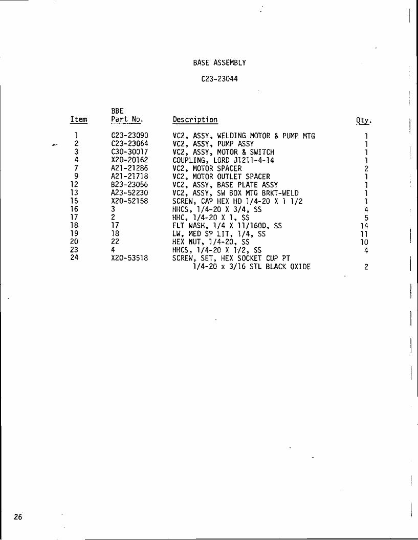
BASE ASSEMBLY
C23-23044
I tern
1 2 3 4 7 9
12 13 15 16 17 18 19 2 0 2 3 2 4
BBE P a r t No.
(223-23090 C23- 23064 C30-30017 X20-20162 A21 -21 286 A21 -21 718 823-23056 A23-52230 X20-52158 3 2 17 18 22 4 X20-53518
Descr ip t ion
VC2y ASSYy WELDING MOTOR & PUMP MTG VC2y ASSY, PUMP ASSY VC2, ASSY, MOTOR 81 SWITCH COUPLING, LORD 51 21 1-4-14 VC2, MOTOR SPACER VC2, MOTOR OUTLET SPACER VC2, ASSY, BASE PLATE ASSY VC2, ASSY, SW BOX MTG BRKT-WELD SCREW, CAP HEX HD 1/4-20 X 1 112 HHCS 1/4-20 X 3/49 SS HHCy 1/4-20 X 1 , SS FLT WASH, 114 X 11/160D, SS LW, MED SP LIT, 114, SS HEX NUT, 1/4-20, SS HHCS, 1/4-20 X 1.12, SS SCREW, SET, HEX SOCKET CUP PT
1/4-20 x 3/16 STL BLACK OXIDE

REF
VlfW A-A P
FIGURE 6. BASE ASSEMBLY

PUMP ASSEMBLY
C23-23064
I tern - 1
* 2 3 4 5 6 7 8 9
1 0 1 1 1 2 1 3 1 4 1 5 1 6 1 7
BBE P a r t No. D e s c r i p t i o n
VC2, VAC PUMP HOUSING VC2, AXLE-VACUUM PUMP VC2, PISTON VC2, TUBE F I T T I N G THD DIAPHRAGM, NEOPRENE VC2, DIAPHRAGM BACK UP PLATE VC2, ASSY, MUFFLER VC2, VC5, ASSY, PUMP HEAD VC29 ASSY, ECC SHAFT & ROD ASSY VENT PLUG CJ-41-5 HOSE CLAMP, 1 1 / 1 6 I D y SCREW TYPE BEARING, BALL, 77-R-10 N.D. RETAINING, RING, 5100-62 TUBING, CONDUCTIVE, 3 / 8 I D X 5 /80D FHMS P H I L 1 0 - 3 2 X 1 /2 , SS HHCS 1 / 4 - 2 0 X 1, SS LN MED S P L I T 1/4, SS

FIGURE 7, PUMP ASSEMBLY '

BBE P a r t No.
MOTOR & SWITCH ELECTRICAL P I C T O R I A L
D e s c r i p t i o n
MTRy EXP. PROOF 1/4 H.P. POWER CORD, 18/3 SO 6 0 0 V 14 SWITCH , G. E. CR101 H 7 0 0 J HEATER, G. E. CR1234 6.80A ELBOW y 90DEG CL I y GRP C , E L 2 9 6 N IPPLE , P IPE , L/2 X 5 - 1 / 2 LG CONN, CORD, EBY2647 BUSHING, REDUCING 3 / 4 X 1 / 2 , RE21 WIRE CONN, PRESS TYPE VC2, MOTOR OUTLET SPACER TERMINAL, SOLDERLESS, R 5 1 0 9 VC2, ASSY, SWITCH BOX COVER

I / L Y Z . LIY
UUM4rCXZLI LUG
wtrr @
8 U L X vEuoN (P~CDM E#YJ (mfl uRJ
CNO /F#OM E U ~ J
FIGURE 8. MOTOR & SWITCH ELECTRICAL PICTORIAL

TOP COVER ASSEMBLY
I tern BBE P a r t No.
~21-21173 A22-22042 A22-22043 11 294 B20-20307 X20-20300 X20-20301 A21-51965 X20-51982 A22-52903 A21 - 52495 A21 -21 671 A21 -21 21 4 X20-20635
D e s c r i p t i o n
VC2, TOP COVER VC2, LABEL, WARNING VC2, NAMEPLATE PHMS, PHIL, 4-40 X 1 /4, SS KEP NUT 4-40 SS GAUGE, VACUUM TEE, 114 F X 1 /4 F X 1 /4 FPT NIPPLE, 114 HOSE I D X 1/4 FlPT VC7, KNOB MODIF-NEEDLE VALVE EXHAUST MUFFLER, 114 MPT VC2, 5, LABEL, VACUUM ADJUST WASHER, FLAT 1/2 1.D X 3/4 OD X -060 TK VC2, DELRIN SPACER VC2, TUBE FITTING THD 23157 & 8, PVC TUBING, 7 & 8 MM F-SET
1 1 1 6 6 1 1 2 1 1 1 - 1 1 1
8 inches

FIGURE 9. TOP COVER ASSEMBLY
I tern - 1 - 2 3 4 5 6 8 9
10 11 12 13 14 15 16
BBE Part No.
B31-21215 A21 -2: 657 A21 -21 658 A21 -21 659 A21 -21 660 A21-21802 X20- 20087 X20-20284 X20-20285 X20-20286 X20-20287 X20-20304 X20-20315 X20-20507 421-21 21 4
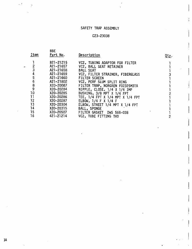
SAFETY TRAP ASSEMBLY
C23-23038
Description
VC2, TUBING ADAPTOR FOR FILTER VC2, BALL SEAT RETAINER BALL SEAT VC2, FILTER STRAINER, FIBERGLASS FILTER SCREEN VC2, PERF SLUM SPLIT RING FILTER TRAP, NORGREN F02325M3TA NIPPLE, CLOSE, 1/4 X 114 IMP BUSHING, 3/8 MPT X 1/4 FPT TEE, 1/4 FPT X 1 /4 MPT X 1/4 FPT ELBOW, 1/4 F X 114 F ELBOW, STREET 1 /4 MPT X 1/4 FPT BALL, SPONGE FILTER GASKET DWS 568-038 VC2, TUBE FITTING THD

FIRS T W F # F S O A I
FIGURE 10. SAFETY TRAP ASSEMBLY

CABINET ASSEMBLY
C23-23171
I tern
- 1 2 3 4 5 6 7 8
10 11 1 2 1 3 1 4 1 5 1 6 1 7 18 1 9 2 0 21 2 2 2 3 2 4 2 5 2 6 27 2 8 2 9 3 0 3 1 3 2 3 3
BBE P a r t No. D e s c r i p t i o n
EXTRUSION, RUBBER BUMPER SCREW, SHOULDER, STL, CAD PLATED VC2, MTG BRKT, FILTER TRAP VC2, SPACER-HINGE DOOR VC2, KNEE HINGE MODIFIED VC2, SPACER BUMPER VC2, BUMPER R A I L VC2, BUMPER-SIDE VC2, NOISE DAMPENER-SIDE VC2, NOISE DAMPENER-BACK VC2, NOISE DAMPENER-DOOR VC2, NOISE DAMPENER-TOP VC2, DOOR-TOP VC2, DOOR-BOTTOM VC2, LINER, INTERMEDIATE SHELF VC2, ASSY, WRAP-AROUND HANDLE, NOVATRONX 10365-1032-25 FERRULE , BRASS NICKEL PLATE WEATHER STRIP, 1/2W X 1 / 8 THK SNAPWELL LATCH, HARTWELL PHMS, PHILL IPS, 8 -32 x 1 / 4 SST PHMS, P H I L L I P S 1 0 - 3 2 x 3 / 8 SST WASHER, FLAT, FENDER # 1 0 WASHER, FLAT #10 PHMS, P H I L L I P S 8 - 3 2 x 3 / 8 SST BHMS, HEX SOCKET, 4 - 4 0 ~ 3 / 8 SST NUT, KEPS # 4 PHMS, PHILLIPS, 6 -32 x 1 / 4 SST NUT, KEPS, X8 PHMS, PHILLIPS, 8 -32 x 1 / 2 SST NUT, KEPS # 6 NUT, KEPS, HEX # 1 0
7 8 i n c h e s 1 1
4 As R e q u i r e d
I 2
1 4 4 I 4 2 1 8 8

I . i I
I 14PLUES 2 R U E S 1 1 R A C U
FIGURE 11. CABINET ASSEMBLY

BB E I tern Part No.
- ~ 2 2 - 2 2 1 8 9 A23-23136 B23-23080 X20-20178 X20-20518 X20-20744 2 1 1 6 3 2 2 6 2 3
VC-2 BOTTLE BASKET ASSEMBLY
Description
VC2, LABEL, BOTTLE TOP VC2, ASSY, BOTTLE TOP MOLDED RUB VC2, ASSY, BOTTLE BASKET BOTTLE, 1400CC, MCKESSON BAG, POLY 2 X 7 FEET, RUBBER, ALASCO #4161 PERMEABLE GAUZE SACK WASHER, FLAT #8, SS WING NUT, 10-32, SS
SECTION V I I I
REPLACEMENT PARTS & ACCESSORIES
1 Each VC-2 unit is supplied with collection bottles, tubing, and a set
of vacurettesB.
I Replacement parts and accessories are listed on the following pages.

Item -
- -- Sizes - Part No.
8mm straight 21655 9mm straight 21413
lOmm straight 21414 l lmm straight 21415 12mm straight 21416
8mm curved 20317 9mm curved 21552
lOmm curved . 21553 l lmm curved 21554 12mm curved 21555
-DJSPDSA&E C04UCTJGN SETS (Part NO. 23116) (Fits 8 to 12mm Vacurettes8 and F VacuretteB Tips 4 to 8mm)

l tern - VACURETTES,' F SET (Set includes Vacurette a. F Tip attached to collection tubing)
- Sizes - Part No.
4mm set 23139 5mm set 23138 6mm set 23135 7mm set 23157 8mm set 23158
VRCURElTER F TIP (Includes fitting for Swivel Handle $23127 or Disposable Collection Set $23127)
Sizes - Part No.
4mm F Tip 21663 5mm F Tip 21664 6mm F Tip 21665 7mm F Tip 21744 - - 8rnm F Tip 21745
ENDOMETRIAL BIOPSY VACURETTEB KIT Part No. (Kit includes mailing cap and bag) 23214
Iottle titting) 23224

l tern - Small
.- -- Medium Large
PERMEABLE GAUZE SACKS (10 sacks per
k; DISPOSA-BOTTLE AND TOP ASSEMBLY
MALE HOSE FITTING (without o'ring)
FEMALE HOSE FITTING
Gasket
Plastic Disposable Bag (100 per Package)
Disposa-Bottle Only
Part NO.
(with o'ring) 21219-B
OJW C o n d u c t i v e R u b b e r O ' R i n g
METAL SWIVEL HANDLE (complete assembly)
Slip Ring ~ h i e a d e d Stop Ring Metal Nut
-. Metal Fitting

CONDUCTIVE PLASTIC HOSE
9 Ft. Long Without Fitting
CONDUCTIVE HOSE - - - - - -
(with metal handle # 23127, and metal fitting f 21218-B)
Part No. 1,
GLASS BOTTLE
BOTTLE TOP -
(complete with fittings and o'ring)
Conductive R u b b e r O I R i n g
Rubber O'Ring
MULTI-TOOTH TENACULUM