model study of - bureau of reclamation · and for people who live in island territories under u.s...
TRANSCRIPT

::::::::
~iiiiiil i~iil
!:i:!?}
%
=iil
iii!!i!i! :~iiiiiii
R-89-17
MODEL STUDY OF ROOSEVELT DIVERSION WEIR
October 1989
U.S. DEPARTMENT OF THE INTERIOR Bureau of Reclamation
Denver Office Research and Laboratory Services Division
Hydraulics Branch

7-2090 (4-81) Bureau of Reclamation
1. REPORT NO.
R-89-17 4, T I T L E AND SUBTITLE
MODEL STUDY OF ROOSEVELT DIVERSION WEIR
7. AUTHOR(S)
Russell A. Dodge
9. PERFORMING ORGANIZATION NAME AND ADDRESS
Bureau of Reclamation Denver Office Denver CO 80225
12. SPONSORING AGENCY NAME AND ADDRESS
Same
~,(~HNICAL REPORT STANDARD TITLE PAGE 3. RECIPIENT'S CATALOG NO.
5. REPORT DATE October 1989
6. PERFORMING ORGANIZATION CODE
D-3750 8. PERFORMING ORGANIZATION
REPORT NO,
R-89-17 10. WORK UNIT NO.
11. CONTRACT OR GRANT NO,
13. TYPE OF REPORT AND PERIOD COVERED
i 14. SPONSORING AGENCY CODE
DIBR
15. SUPPLEMENTARY NOTES
Microfiche and hard copy available at the Denver Office, Denver, Colorado.
16. ABSTRACT
A 1 to 35 scale model study of the Roosevelt Diversion Weir was tested to Improve water recreation safety while maintaining fish barrier effect. The as-built structure produces a hydraulic keeper roller that produces a trapping effect on swimmers and boaters. The as-built structure was tested at several discharges as a base for comparison. Kayak runs over the weir with the apron region and spillway downstream face modified were compared to the base runs. Scour comparisons were also made. After several different configurations were tested, the recommended design modification consisted of one 3.25-foot drop downstream from ogee crest and several 1-foot steps with consecutively smaller tread lengths.
17. KEY WORDS AND DOCUMENT ANALYSIS
a. DESCRIPTORS--
/ *hydraulics/*diversion weir/keeper roller/safety/fish barrier/scour
b. I D E N T I F I E R S - - / Roosevelt Dlverslon Weir/Salt RIver c. COSATI Field~Group COWRR: 18. DISTRIBUTION STATEMENT
SRIM:
I t 9 . SECURITY CLASS 21. NO. OF PAGE. ¢
4O 22. PRICE
(THIS REPORT)
UNCLASSIFIED 20. SECURITY CLASS
(THIS PAGE) UNCLASSIFIED

R-89-17
MODEL STUDY OF ROOSEVELT DIVERSION WEIR
by
R. A. Dodge
Hydraulics Branch Research and Laboratory Services Division
Denver Office Denver, Colorado
October 1989
UNITED STATES DEPARTMENT OF THE INTERIOR "~" BUREAU OF RECLAMATION

ACKNOWLEDGMENTS
The continued help of Bob Roessel of the Salt River Project and Bruce Ellis of the Arizona Projects Office In providing field Information, data, and suggestions Is greatly appreciated. Pete Julius took the documentary videos. Brent Mefford supervised this study.
Mission: As the Nation's principal conservation agency, the Department of the Interior has responsibility for most of our nationally owned public lands and natural and cultural resources. This Includes fostering wise use of our land and water resources, protecting our fish and wildlife, preserving the environmental and cultural values of our national parks and historical places, and providing for the enjoyment of life through outdoor recreation. The Department assesses our energy and mineral resources and works to assure that their development is in the best Interests of all our people. The Department also promotes the goals of the Take Pride in America campaign by encouraging stewardship and citizen responsibility for the public lands and promoting citizen participation In their care. The Department also has a major responsibility for American Indian reservation communities and for people who live In Island Territories under U.S. Administration.
The information contained in this report regarding commercial products or firms may not be used for advertising or promotional purposes and is not to be construed as an endorsement of any product or firm by the Bureau of Reclamation.
i i

CONTENTS
Purpose ...........................................................
Background . . . . . . . . . . . . . . . . . . . . . . . .................................
Model study scope ...................................................
Conclusions ........................................................
Model description
S c a l i n g ° ° ° ° ° ° ° ° ° ° ° ° ° ° ° , ° ° ° ° ° ° ° ° ° ° ° ° ° ° ° ° ° ° ° ° ° ° ° ° ° ° ° ° ° ° ° ° ° ° ° ° ° . . . . ° °
Hydraulic and geometric scaling ...................................... Sediment and hydraulic friction scaling ................................ Kayak sealing ...................................................
Modeling weir modification ............................................
Hydraulic measurements ..............................................
Tests ............................................................... Kayak run tests . . . . . . . . . . . . . . . . . . . . . . . . . . . . . . . . . . . . . . . . . . . . . . . . . . Tests on as-built structure .......................................... Tests on weir configurations using two 3-foot-high steps . . . . . . . . . . . . . . . . . . . .
Tests using upper apron stacked block arrangement . . . . . . . . . . . . . . . . . . . Tests using stacked blocks with the addition of a short triangular
denta te sill extension ........................................ Tests using stacked blocks with long blocks on lower apron . . . . . . . . . . . . . . Velocities measured for fish exclusion . . . . . . . . . . . . . . . . . . . . . . . . . . . . .
Tests using single 3.25-foot step in combination with 1-foot steps . . . . . . . . . . . . . Back eddy tests .............................................. Scour tests .................................................. Tailwater sensitivity tests .......................................
Fish exclusion depths and velocities ......................................
Bibliography ........................................................
Page
2
3 3 3 4
4
4
4 4 5 5 5
° ° °
111

i
C O N T E N T S - Cont inued
Table
1 2
3
TABLES
Summary of confetti velocities, two-step weir geometry . . . . . . . . . . . . . . . Velocities de termined by scale runup method, combined
3.25- and 1-foot step weir geometry . . . . . . . . . . . . . . . . . . . . . . . . . . . Sensitivity tests, kayaks going over weir at station 70 . . . . . . . . . . . . . . . . .
Page
10
11 13
Figure
1 2 3 4 5 6 7 8 9
10
FIGURES
Plan and profile of as-built Roosevelt diversion weir . . . . . ' . . . . . . . . . . . . Keeper roller, as-built weir ..................................... Gradat ion analysis of model sand . . . . . . . . . . . . . . . . . . . . . . . . . . . . . . . Block step ar rangement determined with sectional model . . . . . . . . . . . . . Stacked blocks with triangle extension . . . . . . . . . . . . . . . . . . . . . . . . . . . . Stacked blocks with long blocks on lower apron . . . . . . . . . . . . . . . . . . . . . Single 3.25-foot step followed with a ser ies of 1-foot steps . . . . . . . . . . . . . Recommended block ar rangement . . . . . . . . . . . . . . . . . . . . . . . . . . . . . . Bed profiles along apron sill ................................... Tailwater curve used for model study . . . . . . . . . . . . . . . . . . . . . . . . . . . .
15 16 17 18 19 20 21 22 23 24
Kayak per formance
APPENDIX
1@OQQI@OQOQQIQOQDIJQQIQQOO@QDQUQIg@QIQOOI 25
iv
PURPOSE
A 1 to 35 Froude scale hydraulic model of the entire Roosevelt Diversion Weir (fig. 1) was tested to investigate poss~le structural changes. The main objective was to improve the recreational safety of flow on the structure while maintaining the fish barrier effect of the weir. An investigation was conducted on recommended changes that resulted from earlier tests on a 1:18 scale sectional model. The effect of an approach channel, a downstream channel, and abutment boundaries on the recommended design was of primary interest.
BACKGROUND
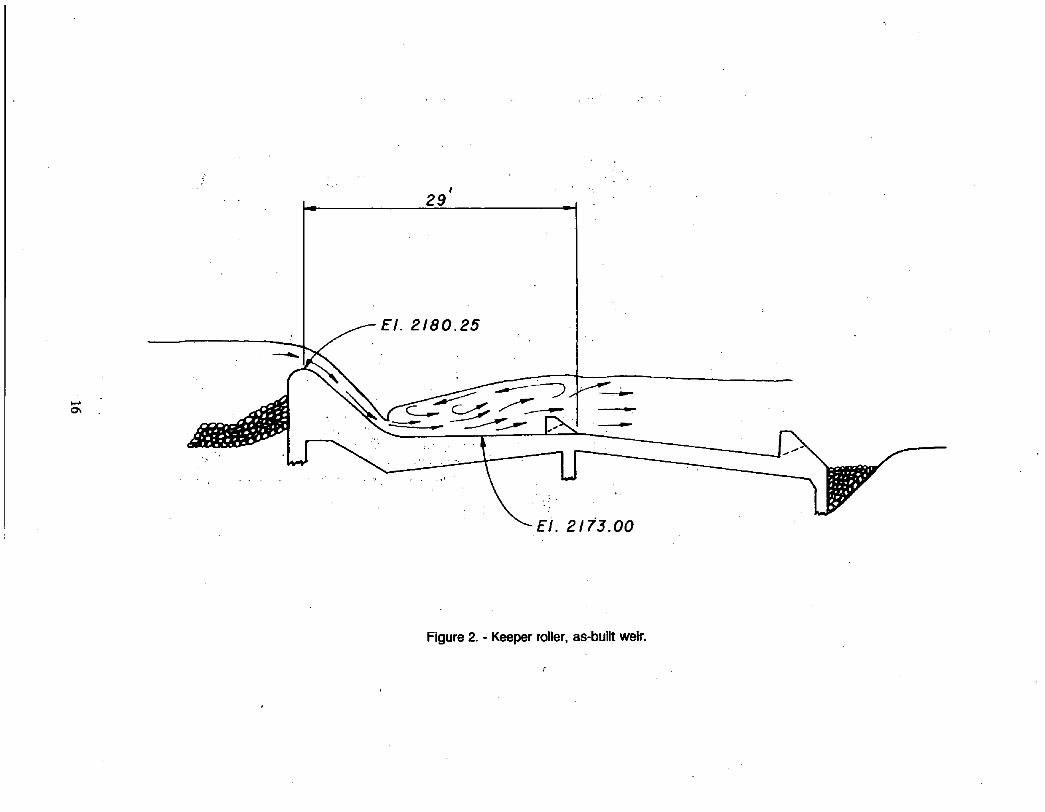
The as-built ogee crest weir, by design, creates a strong hydraulic jump (keeper roller) on the downstream apron (fig. 2). The jump dissipates energy and reduces potential for downstream channel scour. The flow accelerates as it passes over the weir crest and plunges down the downstream face of the weir. After entering the tailwater, the high-velocity flow continues to travel downstream along the apron floor. The submerged high-velocity flow drives a counterclockwise vertical roller over the apron in the tailwater. Flow at the surface therefore moves upstream toward the weir face. Although the as-built weir performs well hydraulically, the strong keeper roller action produces a trapping effect on swimmers and boaters. Davis and George (1985) have shown that changing a standard ogee crest drop structure into a series of steps can reduce the keeper roller action. This improves recreational safety of flow over spillways and weirs.
The following are study objectives that were not addressed in the tests on the sectional model:
Effects of approach topography, that is, the unit discharge variation and skewed velocity along the crest.
• Back eddies downstream of the weir caused by abutment and channel topography.
• Scour variation along the full length of the downstream apron sill.
• Possible abutment effects that could locally reduce fish barrier capability.
Variation of boater safety along the full length of the aprons.
MODEL STUDY SCOPE
All modifications tested involved the placing of steps on the downstream side of the weir. Initially, the study was limited to testing step width geometries with two steps, each 3 feet high. Three- foot-high steps were chosen to ensure the exclusion of fish. The study was later expanded to include additional tests investigating a single 3.25-foot-high step down from the weir crest followed by a series of smaller steps down to the level of the lower apron. The single 3.25-foot step was maintained as a fish barrier. Different step heights and lengths downstream of the major step were tested to improve recreational safety of flow over the structure.

CONCLUSIONS
1. For a given total discharge, the unit discharge varied along the weir crest. The upstream topography forced most of the riverflow to the left side.
2. In the as-built structure, kayaks were trapped in keeper rollers for all flow conditions tested.
3. The combination of a 3.25-foot step with its top at elevation 2180.25, followed by a series of 1-foot steps with different tread length yielded the best hydraulic conditions for recreational safety and maintained the fish barrier effect of the structure. Kayaks moved out of the apron region at all discharges. However, at a discharge of 1,000 ft'/s, kayaks that passed over the weir near the right abutment caught on the diagonal line of dentates that surface at elevation 2175 feet. Removing these dentates is recommended. For all cases with depths greater than 1 foot, flow velocities on the steps were close to or exceeded 10 ft/s.
4. The intersection of the weir and the right abutment facing caused low velocity on a rather gentle slope and could provide a pathway for fish. This area of the structure should be changed to ensure a definite 3-foot drop, forcing all flow to drop away from the abutment facing.
5. The full-length weir model verified the sectional model results in that the stacked block arrangement on the upper apron provided the best flow conditions of the two-step arrangement tests.
6. For the two-step geometry, rollers on the lower step trapped kayaks either temporarily or permanently depending on their location along the weir length. The diagonal flow forces trapped kayaks to the right, an area of lower flow. The kayaks often moved out of the apron region and downstream after traveling parallel to the weir for a short time.
7. The formation of surface keeper rollers downstream of the two-step weir geometry was sensitive to small changes in tailwater at specific discharges. Surface flow and thus kayak performance were affected by tailwater elevation.
8. The model provided only relative scour comparisons because it did not simulate the sediment discharge of the river. The scour depths at the apron sill were about the same for all the upper apron block arrangements tested and for the as-built weir. From 70 to 140 feet downstream from the sill, scour was two to three times the scour at the sill. When blocks covered the lower apron region, end sill scour increased by a factor of 4 compared to tests without blocks on the lower apron.
9. When the steps did not extend to the left in front of the sluiceway, flow dropped off the block side edge and concentrated on the apron sluiceway invert. This caused an increase in the left bank scour.
10. Modifying the weir by adding steps to the downstream side of the weir did not cause identifiable changes in the abutment back eddies.
2
MODEL DESCRIPTION
The model represented in fixed bed form about 1,000 feet of approach river and a point of land that changes from a peninsula to a large island at discharges greater than 10,000 ft3/s. Part of the fixed bed near the weir was placed low to allow for fine sand on top to represent silt bars. The river valley and the entire diversion weir (fig. 1) were modeled from bank to bank. Medium sand was contoured to model 600 feet of downstream river topography. The downstream bed was movable for easier comparisons of bed scour.
SCALING
Hydraulic and Geometric Scaling
A model scale of 1 to 35 was selected based on hydraulic laboratory space and pump discharge limitations. Using Froude law and the model scale ratio, variables scale as follows:
Length ratio Lr = 35
Discharge ratio Q, = 1_~ s/2 = 7,247
Velocity ratio V , = L, m = 5.92
Time ratio T , = L, l/" = 5.92
Unit discharge ratio = L~/2 = 207
Pressure/shear ratio P, = L,
Where:
L, = the ratio of prototype to model:
Friction, shear, and stage will scale if the friction ratio f, is equal to 1. Computing the friction ratio using Darey-Weisbach flow equation for open channel flow (Rouse, 1950) and,Moody-type friction factor curves estimates model friction performance. This results in f~ for 10,000, 5,000, and 2,000 fP/s of 0.98, 0.90, and 0.70, respectively. Although the friction ratio is far from 1.0 for 2,000 ft3/s, this deviation is not significant for short friction reaches such as modeling flow over the crest and apron sill. Froude scaling is therefore sufficient if model depths and Reynolds number are not too small causing surface tension and friction to override Froude scaling.
Sediment and Hydraulic Friction Scaling
Model sediment was scaled based on conversations with field personnel and on photographs. Generally dgo or the 90-percent sieve passing size governs the hydraulic roughness. Fo r sediment,
• geometric and particle-settling-velocity scaling are the same for prototype particles with diameters in millimeters equal to and greater than L,, the scale ratio. Thus for the model, a 1-millimeter particle represented a 35-miUimeter prototype panicle. Larger panicles were scaled according to
3
the model length ratio of 1 to 35. The gradation analysis for two samples of the model sand is presented on figure 3. The equivalent prototype analysis is :shown .down to about the geometric scali~g limit. These gradations indicate that the model sand represents a mean prototype diameter or a d~o ~o f about 40 m ~ e t e r s . ' ~ e .characteristic hydraulic roughness Size, 'c190, is about 152 :millimeters. ~ :
Kayak Scaling -. .
The kayaks were designed to :scale by weight and draft. However, the location of the center of buoyancy relative to the center of weight did not scale. Therefore, sideways spinning of kayaks in 'the roller trough may :not be accurately represented. However, the :forward momentum :hdping to drive the kayaks past the keeper :roller was sealed. The ~effect "of paddling to keep :the kayaks pointing in the direction of the flow was not considered.
MODELING WEIR MODIFICATION
Modifications to the ,prototype weir were to be made either using concrete-filled .fabric `forms or cast-in-place concrete .as .'an :alternative. in-the sectional :model, :sand .bags were successfully used .to simulate the concrete:filled `fabric forms. However, p r e ~ i n a r y attempts using small sand bags caused pr6blems in the smaller model. Flowing water deformed :the ibags ;too ~much in :relation ,to the depth in the model:; therefore, :concrete 'blocks and wood were used :to 'simulate ,the weir modificatlon~s.
HYDRA=ULIC !MEASUREMENTS
Permanently hastailed ~ b r a t e d Ventur:i meters :are ;used iin the :hydraufic laboratory to measure model river discharge. Mercury ,manometers indicate :the ;head d~ferent:ial across ~the Ven~uri meters. A laboratory volumetrie tank and electronic'timer are ,used ,to calibrate the Ven'turi meters and manometer. Thus 'the measured flow rates *have a traceable :aCcuracy 'of - 1 :.percent.
Because of the shallow flow 'on top of the blocks, it was not possible to measure velocity with probe-type measuring devices. The two methods used for measuring velocities on the steps 'are:
1. Timing confetti travel for a known distance using ,a video taping technique.
2. Measuring velocity head by the scale runup method, :a method 'that is;based on ~measur:ing flow runup 'on a scale.
TESTS
Kayak Run TeSts
Observations were made with kayaks going 'over the weir at stations 70, 210, 250, 280, ,and 385 :feet from the :sluiceway. For the model study, all stations along ;the crest were referenced to the
4

sluiceway/weir crest intersection point on the left side of the structure. Test runs were generally made with discharges of 2,000, 5,000, and 10,000 ~/s .
At low flow and on the right side of the weir, the kayaks caught on the crest and at times on the downstream sloping part of the weir. These "beached" kayaks were assisted over the weir by pushing gently by hand. Tests consisted of observing surface flow over the apron region and kayaks passing over the weir. Descriptions of all kayak runs are in the appendix in tabular form; the more important of these tests are described in narrative form.
Tests on As-Built Structure
The model kayaks became trapped in the keeper roller at all entry points along the weir and for all of the discharges tested.
2,000 W/s. - Kayaks that passed over the weir on the left side traveled parallel to the weir until they reached about station 280 (measured in feet from the sluiceway to the right) where they became permanently trapped. Kayaks passing over the weir at locations other than the left side were held against the downstream weir slope face near the point at which they crossed.
5,000 ~/s . - Kayaks were trapped in the keeper roller all along the weir and traveled sideways from left to right parallel to the downstream face of the weir until reaching about station 315. At station 385, the kayaks remained on the roller over the apron with no side travel.
10,000 ft~/s. - The kayaks traveled sideways from the left side to station 295, were trapped, and held in place. When passing over the weir near station 385, the kayaks remained trapped with no side travel.
Tests on Weir Configurations Using Two 3-Foot-High Steps
Test observations were compared with baseline tests of the as-built structure. Blocks with different tread lengths were placed on the downstream side of the weir. These blocks formed continuous steps along the entire length of the weir.
Tests using upper apron stacked block arrangement. - This arrangement was the recommended design based on the sectional model results (fig. 4). Nonuniform flow along the weir crest induced diagonal flow over part of the middle crest. The diagonal flow caused a jump wave and keeper roller to form on the lower block, along the row of dentates. This caused.lateral flow along the keeper roller toward the right. :~
2,000 fP/s. - Kayaks that passed over the weir at station 70 remained trapped but moved to the right about 35 feet along the weir. For station 210 and higher, kayaks caught on the weir crest or the first step. When the kayaks moved down the weir tO the tailwater, they remained trapped in a weak roller caused by flow dropping steeply off the upper block into the tailwater.
5,000 fP/s. - The kayaks moved out of the apron region immediately when entering the weir at station 70. Entering at station 210, the kayaks traveled sideways to station 310 and remained trapped. When going over the weir at station 280, they traveled sideways to about

station 330 before they stopped and remained trapped. The kayaks became immediately trapped when they entered at station 385.
10,000 fP/s. - From station 70 to station 120, the kayaks moved out of the apron region immediately. Entering at station 210 the kayaks traveled 105 feet sideways then moved out of the apron region, taking about 24 seconds. The kayaks moved out of the apron region immediately at stations 280 and 385.
Tests using stacked blocks with the addition of a short triangular dentate sill extension.. The step arrangement on the upper apron with the addition of a 3- by 1.5-foot triangular extension to the downstream slope (fig. 5) of the dentate sill reduces roller action significantly at 2,000 ft3/s. The extension produced little effect from 5,000 to 10,000 ft3/s.
2,000 fP/s. - At all entry stations, the kayaks temporarily caught on the crest and steps then moved out of the apron region.
5,000 fP/s. - The kayaks moved out of the apron region immediately when entering at station 70. A keeper roller formed at an angle to the weir, crossing the dentate sill of the upper apron at about station 210. Entering at station 210, kayaks sometimes remained trapped permanently after 70 feet of side travel and at other times moved out of the apron region immediately. From all entry points starting at about station 245 the kayaks became permanently trapped in the roller over the apron.
10,000 ft3/s. - Going over the weir at stations 70 and 210, the kayaks moved out of the apron region immediately. Entering at station 280 they moved out of the apron region after about 6 seconds of side travel to the right. Kayaks moved out of the apron region immediately entering at~ station 385.
Tests using stacked blocks with long blocks on lower apron. - Placing blocks on the lower apron along with the stacked blocks on the upper apron (fig. 6) caused a violent jump on the lower blocks on the left side of the weir. At 5,000 and 10,000 fP/s, the keeper roller tossed the kayaks roughly. Similar results were found in the sectional model tests.
2,000 ft3/s. - The kayaks remained trapped when going over the weir at station 70 and moved out of the apron region at the remaining stations.
5,000 ft3/S. - A keeper roller formed on the lower apron blocks at the left side of the weir. Kayaks remained trapped after passing over the weir at station 70. The kayaks moved out of the apron region entering at station 210 and remained trapped after going over the weir at stations 280 and 385.
10,000 ft3/s. - A strong keeper roller formed over the lower apron blocks on the left side of the weir. Kayaks that passed over the weir at station 70 temporarily remained in a violent roller. After a period of time, the kayaks escaped and moved out of the apron region. Kayaks also temporarily' remained trapped when going over at station 210. The kayaks moved out of the apron region going over the weir at stations 280 and 385.
6

Velocities measured for fish exclusion. - Brink velocities measured on the upper block using the confetti method are summarized in table 1. All velocities exceeded 10 fi/s for the flow rates measured.
Tests Using a Single 3.25-Foot Step in Combination With 1-Foot Steps
Initially, a weir design using a 3.25-foot step followed by a series of 1-foot steps of uniform tread length was tested (fig. 7). Surface flow conditions and kayak passage had improved when compared with the conditions documented for the two-step design. The only keeper rollers which permanently trapped kayaks formed as weak rollers immediately downstream of steps. To improve this condition, through testing, the step tread lengths were altered to a progressively shorter downstream pattern, figure 8. Tests of the final tread length geometry were expanded to cover flow rates from 1,000 to 38,000 fP/s. The following observations were made for each flow.
1,000 fP/s. - Kayaks needed assistance off the top block and moved out of the apron region when going over the weir at all stations. Entering at station 210 the kayaks were temporarily trapped, during which time they traveled sideways about 20 feet. At station 280 kayaks hesitated slightly then moved out of the apron region.
2,000 fP/s. - Entering at Station 70 the kayaks moved out of the apron region immediately. Again the kayaks were temporarily trapped when entering at station 210. They traveled sideways 15 feet then moved out of the apron region. At all other stations the kayaks moved out of the apron region downstream immediately. An assist was necessary at station 385 to move the kayaks over the weir. On the right side, the kayaks sometimes were held against the diagonal line of apron dentates.
5,000 ~ / s . - Kayaks passed over the weir at all stations.
10,000 fP/s. - A weak roller formed downstream of a large standing wave located near the end of the lower apron. At station 70 the kayaks became temporarily caught in the downstream roller. They traveled sideways a short distance downstream of the lower apron dentates before moving downstream. At stations 210 and 280 the kayaks moved out of the apron region immediately. At station 385 they slowly traveled sideways 20 feet taking about 45 seconds and then moved out of the apron region.
15,000 fP/s. - The kayaks traveled sideways 35 feet and then moved out of the apron region after passing over the weir at station 70. The kayaks immediately moved out of the apron region at the remaining locations along the weir.
20,000 fP/s. - Starting at station 70, the kayaks spun sideways in the roller trough, traveled sideways 35 feet, taking about 6 seconds, and then were free of the roller. The kayaks immediately moved out of the apron region throughout the remainder of the weir.
38,000 fP/s. - Kayaks that passed over the weir at station 70 moved out of the apron region immediately. Between stations 210 and 280 they traveled sideways 35 feet and then moved out of the apron region. At station 385 they moved out of the apron region and over the diagonal dentates.
7

Back eddy tests. - Confetti was used to trace surface velocity paths in the back eddies near the downstream right and left abutments. Eddy velocities were not affected by the upper apron block arrangements tested. On the right side, eddy velocity varied from about 1.25 to 3 ft/s. The eddy velocity on the left abutment varied between 2 and 4 ft/s. However, the eddy size increased with discharge. The diameter of the back eddy on the right side varied from about 25 to 50 feet and on the left from 100 to 300 feet in length for discharges of 2,000 and 10,000 ft~/s.
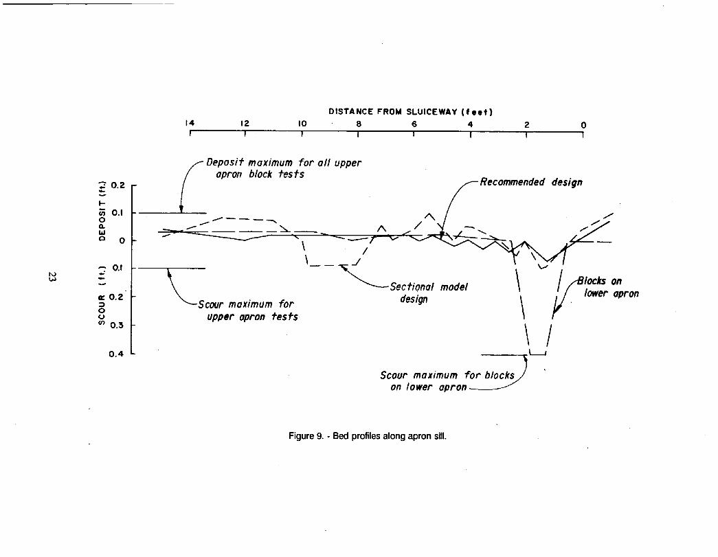
Scour tests. - End sill scour tests were run for 30 hours with a discharge of 10,000 ft3/s. Comparing scour for different block arrangements on the upper apron (fig. 9) indicated that the location of maximum scour changed. However, the depth of maximum scour remained about the same for all block arrangements. The variation in scour location was mainly the result of variation of transport rates from simulated silt bars placed on the hard topography in the weir approach region. Since the model did not simulate the river sediment transport rate, the scour depth and location would not scale. However, comparisons of relative estimates of scour performance are possible. These relative comparisons indicate that the maximum scour was about the same regardless of the tested block arrangement on the upper apron and for the existing structure. For all upper apron block arrangements, the deepest scour, about two to three times the end sill scour, occurred at distances from 70 to 140 feet downstream of the sill.
Placing blocks on the lower apron nearly covered the upstream face of the second row of dentates (fig. 6). Tests run with this configuration resulted in four times the apron scour previously measured. The major scour occurred immediately downstream of the lower apron on the left side near the sluiceway. .
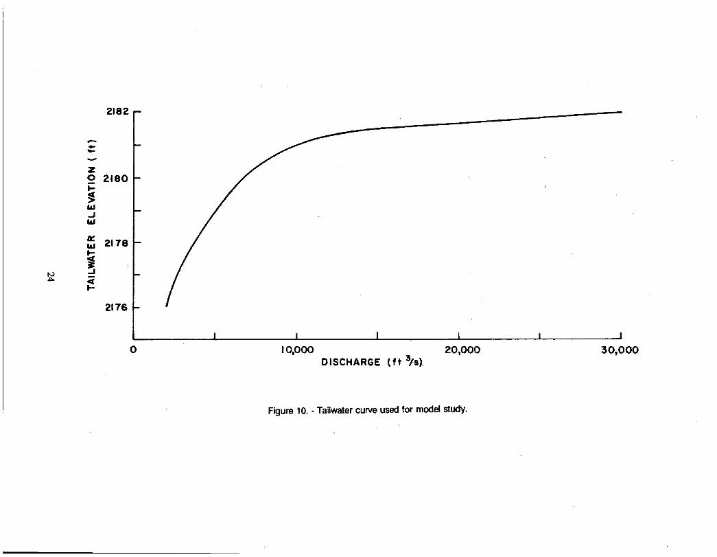
Tailwater sensitivity tests. - Observations during the testing of the two-step weir geometry showed that occurrence and location of keeper rollers are fairly sensitive to small changes in tallwater elevation. To help evaluate the step modification, a series of sensitivity tests were conducted to define the influence of tallwater on boater safety. These tests were conducted on the block arrangement as given on figure 5. Kayak performance tests were conducted at 2,000, 5,000, and 10,000 ft3/s varying the tailwater -0.35-foot around the target elevation. The target elevations were based on tailwater depths provided by. Reclamation's Sedimentation Section (fig. 10). The test summary, table 3, shows the kayak performance with this arrangement as function of tailwater at specific discharges. These results show. that relatively small changes of tailwater can alter kayak performance for the two-step weir geometry:: . . .
Tailwater sensitivity tests were not conducted on the combined 3.25- and 1-foot step geometries, as strong keeper rollers were not observed in the tests. Therefore, small changes in tailwater are not expected to alter surface flow patterns.
FISH EXCLUSION DEPTHS AND VELOCITIES
Velocities using the scale runup method and flow depths for the recommended block arrangement (fig. 8) are summarized in table 2. Velocities were measured at the brink on top of the 3.25-foot- high step and on the next lower step, 3 feet downstream from the plunge point. As a general design guide for fish exclusion at the Roosevelt diversion weir, velocities greater than 10 ft/s were needed if flow depths exceeded 1 foot. Based on the velocities in table 2 compared with this requirement, the structure will act as a fish barrier.
8

BIBLIOGRAPHY
Davis and George, Mode/Tests of Little Falls Dam - Potomac River, Maryland, U.S. Army Waterways Experiment Station, May 1985.
Rouse, Elementary Mechanics of Fluids, Wiley, 7th printing, 1950.

Table 1. - Summary of confetti velocities, two-step weir geometry (fig. 5)
Discharge (ft3/s) Station (ft) Velocity (ft/s)
10,000
5,000
2,000
70 17 210 11 385 11
70 14 210 13 385 11
70 13 210 12 385 14
10

Table 2. - Velocities determined by scale runup method, combined 3.25-and 1-foot step weir geometry (fig. 8)
Discharge (~/s) Station (ft) Depth (ft) Velocity (ft/s)
1,000 70 0.46
0.43
7.2, (Brink of top step)
9.0 (3 ft downstream of the plunge point on second step)
210 0.23 6.7 0.23 7.7
• 280 0.23 5.4 0.23 8.2
385 0.12 5.4 0.12 6.1
2,000 70 0,58 8.6 0.34 13.0
210 0.46 7.7 0.34 9.4
280 0.34 7.2 0.34 9.8
385 0.23 7.2 0.23 7.7
5,000 70 1.50 10.5 1.00 14.4
210 1.00 10.2 0.92 13.3
280 0.90 9.4 0.80 12.5
11
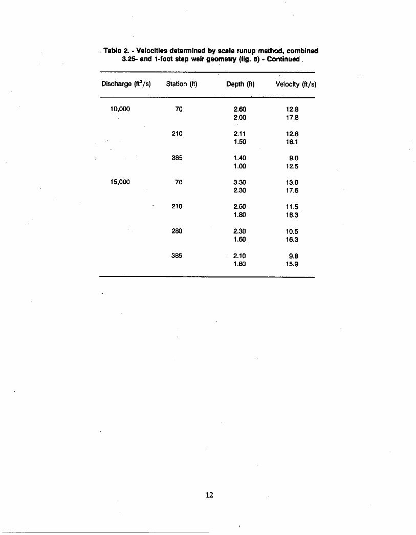
• Table 2. - Velocities determined by scale r u n u p method, combined 3.25- and l-foot step weir geometry (fig. 8) - ConUnued
Discharge (ft3/s) Station (ft) Depth (ft) Velocity (ft/s)
10,000 70 2.60 12.8 2.00 17.8
210 2.11 12.8 1.50 16.1
385 1.40 9.0 1.00 12.5
15,000 70 3.30 i3.0 2.30 17.6
210 2.50 11.5 1.80 16.3
280 2.30 10.5 1.60 16.3
385 2.10 9.8 1.60 15.9
12

Table 3. - Sensitivity tests, kayaks going over weir at station 70 (fig. 5)
Discharge (fta/s) Tailwater offset (ft) Comments
10,000 +0.35 ft
Target elevation 2181.5
Kayak traveled sideways on roller from Sta. 193 to Sta. 298, escaped in 47 seconds.
Kayak traveled sideways on keeper roller elevation from Sta. 192 to Sta. 315, escaped in 30 seconds.
-0.35 ft Kayak traveled sideways on keeper roller from Sta. 214 to Sta. 350, escaped in 47 seconds.
5,000 + 0.35 ft Kayak traveled sideways on keeper roller from Sta. 210 to Sta. 385, remained trapped.
Target elevation 2179 ft
Kayak was trapped Intermittently at locations In a weak roller between Sta. 285 and 385.
2,000
-0.35 ft
+0.35 ft
Traveled along weak keeper roller between Sta. 280 and 315 in 6 seconds. Then kayak escaped moved out of the apron region.
Traveled along weak keeper roller from Sta. 0 to Sta. 420. Remained trapped in shallow flow near dght abutment.
13

Table 3. - Sensitivity testa, kayaks going over weir at station 70 (fig. 6) - Continued
Discharge (ftS/s) Tallwater offset (ft) Comments
Target elevation 2176 ft
-0.35 ft
The kayaks moved out of the apron region.
Keeper roller formed Just downstream of upstream dentate sill. Kayaks escaped moved out of the apron region when'entering Sta. 175 and 210. Kayaks remained in a weak roller at all other stations.
14

l l . l l l l l llO
~t ! i
i t :
I
/ !
(
i i !
I o
i
, i ~,.
, I i l l I I . . .<.1 P~ l i l ~ns oi" oe, i l ino l | C '~!
! ' i ~ i l ru i lm '# .
• Cmttr l lc l ion iolnls "1". A l t on i l t l l l s l~ l . ~- I ..,'',, '4 i ' l / . , ~ .... ~1 I~,,,,,;
)L C
=I •
I I ' D I I ~ f i l # a l i l i l l
< ~ ! : ~ " : ~ " / : i..--- ' l l . in t~ ,~ ,~ c~ '~ r l l f . . . ..,J i i ( * . < , ° , . , , P, ,
, , , , l l . iO / \ ~ ~ r ~ ' i : ' ....
t / ~ i / - - . I ' . -)''''''®
:" / " J / ~ . o I ,
#11.
I ~" I ,'
P L A N " / / I -~-"~ , ,,,,
",- ,. ~ . . . k . . . . . ~ . . . . . . . ~ i ' l l I I i l o i l I to i ¢ , i l llF I l l l ~ I l l 'at !1.111100
," ~" II I t i l l '~", " • • 50 t1 '0 " " i t I l l f - "L'I'IO" I I I l l l iS q l l , , , , .~ i .' ! i ~, ! , . i . t . - : : / l ! i ' o l o o
. . . . . , . , ..................................................................... .... ~i; " - . . . . . . . . ~ ~,JL,. qP I
• . . . . . . • n l / ' r ol0 Ik ! ' ilh~l.lln P c i l l l l . " ............................................. . . - - ~-"
UPSTI~EAM P W O I C l L (
Figure 1. - P lan and profi le of as-bui l t Rooseve l t d ivers ion weir .
O~
i
2 9
Figure 2. - Keeper roller, as-built weir.

"-,I
7-1415 (11-70) Ehlceau o | R e c l a m o t l o n
251. 71 - 45 mla IS mhl i w T
HYDROMETER ANALYSIS TIME READINGS
60 mlJ 19 rain 6 rain
M
7O
"" l z
o,, I ~
i cJ at
llO
10
I I I I I I 0 _ =. ~ ~
.019
FINES
G R A D A T I O N T E S T SIEVE ANALYSIS I U.S. STANOARO SER,ES I
• ' ' . i |
I I I I
I I
I I
I I Model fwo somples-
ill, I 1 ' I '
I I i / '
y./* ' I I I I //,,, , I I / , I
/ , 1 1 1 ' I I
, , , , , ~ : : : : : ,1, , , , , : I J
. 0 3 7 .074 .149 .297 .590 1.19 2.38 4.76 D IAMETER OF P A R T I C L E IN M ILL IMETERS
s.NCD I , - i - , ° - i ~ o , - I
CLEAR SQUARE OPENINOS s/4" ! ~,, 3" s"
t
I I I I !
I I I I I I
I I I I I I I I I I I I ¢=
I 9.52 19.1 38.1 76.2
20
30
a
.¢ i - au m
SO i " X lU U I¢ I
+0 •
70
I I B0 I ! I I ! 9O I
I I : 100
127 152
(~RAVEL ] COBBLES FINE I COARSE
F i g u r e 3. - G r a d a t i o n a n a l y s i s of m o d e l s a n d .

O0
El . 2_180. I I I
13 - 9
El . 2_179.00
• -~---EI. 2176..00
Figure 4. - Block step arrangement determined with sectional model.

Crest 29'
' J " I I I
El. 21 . . [_ _ 13 - 9 ~ - E I . 2179.00 - E l . 2176.00
f EI. 2_173.00
Figure 5. - Stacked blocks with triangle extension. ..

_•Crest . I I t
39 - 3
El. 2180.25"~ 13 - 3 _,_ 26 \ El 2179.00
#
--0.
%.
~ o
----,--El. ,2176.00
~'~ s E l . 2173.0 0
Figure 6. - Stacked blocks with long blocks on lower apron.

t ~ i - .x
~ E I . 2177. O0 I I ~ i I I
El. 2.180.25 i_ 9 i~. 5 ~_ 5 =I~ 5 ~_I~ 5 ~.----EI. 2.176.00
I .---------'El. 2175.00
----------El, 2174.00
~ - - - E I . 2173.00
Figure 7. - Single 3.25-foot step followed with a sedes of 1-foot steps.

t ~
I #
7 - 6 El. 2 1 8 0 . 2 5 ~
I
29
I I I I I I
/ 0 - 6 6 - ~ j
~ ~ E l . ,2177.00
~ EI. :2176.00
/ ~ , ~ E I . ZI75.00 / ~ E I . z ~ 7 4 o o
_ I
Figure 8. - Recommended block arrangement.
1 4 1 2
I !
DISTANCE FROM SLUICEWAY ( f e e t ) I0 8 6 4 2 0
I I I I I I
0.2 le,.
h -
0 O. IJJ
0
- - " 0 .1
¢ 0 . 2
0 U
0.:5
0 .4
~ - Deposif • ~ apron
maximum for oil upper block fesfs
f
\ i \
i
~ S c o u r maximum for upper apron fesfs
-- -- ~ ' ~ S e c f i o n o l mode/
~ f-- Recommended design
I design I lower opron
t ,
Scour maximum for blocks J on lower apron
Figure 9. - Bed profiles along apron sill.
2176
2182 -
~ 2 1 8 0
w
2178
B
0 I J I
I 0 , 0 0 0 DISCHARGE ( f t 3/S)
I ! 20,000 30,000
Figure 10. - Tailwater curve used for model study.

APPENDIX
Kayak Performance
25

Flow rate Entry point
from sluiceway (ft) Action
2,000
5,000
10,000
70
210 280
385
70 210 280 385
70 210 280 385
No blocks in use (figs. I and 2)
Traveled laterally 105 feet, then stayed trapped at slope face of spillway
Traveled laterally 70 feet, but stayed trapped at face Over crest with assist, 1 and stayed trapped at spillway
slope face Traveled over crest, but stayed trapped at spillway
slope face
Traveled laterally 140 feet, but stayed trapped Traveled 105 feet, but stayed trapped Trapped with 35 feet of side travel Caught on crest, if assisted would be trapped with no
side travel
Traveled 140 feet, but stayed trapped Traveled laterally 70 feet, but stayed trapped Trapped with 15 feet of side travel Trapped in foam with no side travel
Short block on top of long block (fig. 4) recommended from sectional model study
2,000 70 210 280 385
Trapped with 35 feet of side travel, stuck in roller foam Trapped on upstream edge of top block Stuck on top of crest Stuck on top of crest
5,000 70 210 210
280
385
Went through Immediately Trapped on downstream edge of block Traveled laterally 210 feet, but stayed trapped; roller
wave crossed dentate on lower block Traveled laterally 50 feet, and moved out of the apron
region in 80 seconds Moved back and forth, but stayed trapped
10,000 70 210
280 385
Moved out of the apron region Immediately Traveled laterally 105 feet In 24 seconds, then moved
out of the apron region Moved out of the apron region Immediately Moved out of the apron region Immediately
1 At times kayaks would beach on the weir and would need an assist to free them.
2?

Flow rate Entry point
from sluiceway (ft) Action
10,000
Lower upper apron block only (fig. A-1) 2
70 210 280 385
Moved out of the apron region Immediately Trapped with 140 feet of side travel Trapped with 100 feet of sidetravel Trapped with no side travel
2,000
5,000
Stacked blocks On upper apron, long block on lower apron (fig. A-2)
70 210 280 385
70
210 250
280 385
Roller on lower apron block, trapped Moved out of the apron region Immediately Moved out of the apron region Immediately Moved out of the apron region Immediately
10,000 70 280
Trapped violently spinning, after 90 seconds and 70 feet of side travel was expelled
OUt Irn'medlately Trapped for 18 seconds, after 70 feet of side travel was
expelled Trapped on downstream upper apron top block Trapped on downstream upper apron top block
280 385
Trapped and tossed violently out in 30 seconds Traveled sideways for 70 feet in 30 seconds, then
moved out of the apron region Moved out of the apron region Immediately Moved out of the apron region Immediately
Stacked blocks on upper apron and 3- bY 1.5-foot triangular dentate sill extension (fig. 5)
2,000
. • ; . .
70
210
280
385
70 " ~ 210
210
245 280 385
5,000
Temporarily caught on crest, bottom scraped blocks, then moved out of the apron region with slight hesitation
Caught at upstream edge of top block, scraped blocks, tumbled sideways, then moved out of the apron region
Scraped, then moved out of the apron region Immediately
Assisted off crest, then moved out of the apron region
Moved out of the apron region Immediately Roller crosses dentates, 70 feet of side travel, trapped
permanently Roller crosses dentates, then moved out of the apron
region Immediately Trapped permanently after 35 feet of side travel Trapped permanently Trapped permanently
2 All figures with prefix A are figures at the end of the appendix.
28

Entry point Flow rate from sluiceway (It)
\ 10,000 70
210
280
280 385
Action
Moved out of the apron region Immediately Roller crosses dentates and kayak moved out of the
apron region immediately Moved out of the apron region after 6 seconds of side
travel Moved out of the apron region immediately Moved out of the apron region Immediately
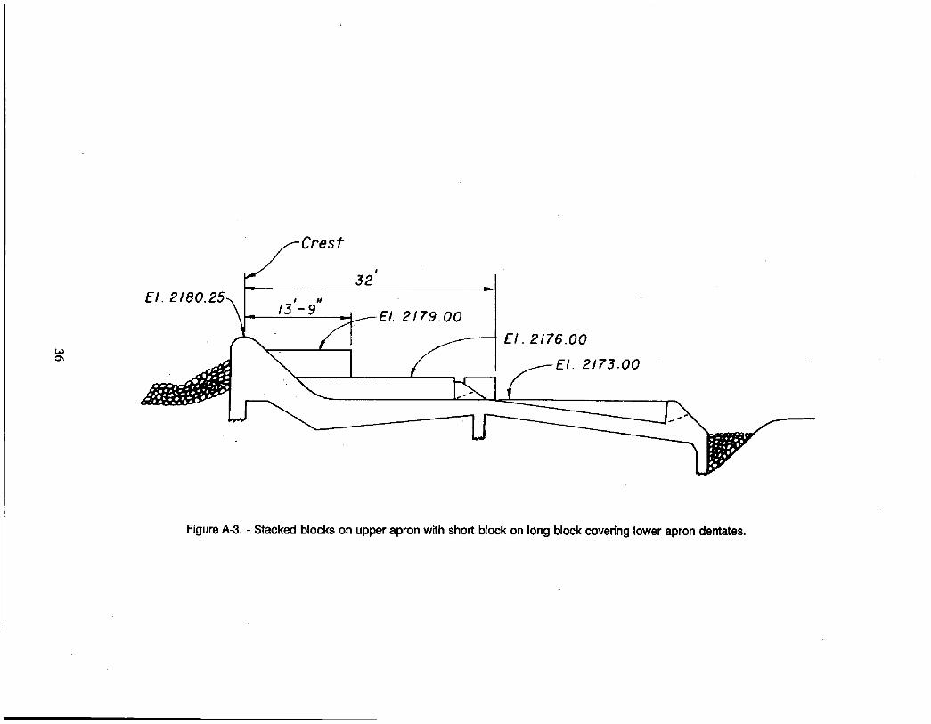
Stacked blocks on upper apron with short block on top, long block covering lower apron dentates (fig. A-3)
2,000 70 210 280 385
Trapped with no lateral motion Remained trapped after 105 feet of side travel Trapped Trapped
5,000
10,000
70 210 280
385
70 210 280 385
Moved out of the apron region Moved out of the apron region Trapped Just downstream of top block of upper
apron, 105 feet of side travel Trapped after 15 feet of side travel
Moved out of the apron region Moved out of the apron region Moved out of the apron region Trapped after 15 feet of side travel
Stacked blocks on upper apron with short top
2,000 70
210
280 385
5,000 0 210
• 280 385
10,000 70 210
280 385
block covering upper apron dentates (fig. A-4)
Scraped upper blocks, after assist traveled 35 feet sideways, and was trapped In foam
Scraped on upper block, after assist traveled 70 feet sideways, and remained trapped
Assisted, trapped Assisted, trapped
Moved out of the apron region immediately Moved out of the apron region immediately Traveled sideways 70 feet, remained trapped Trapped after 35 feet of travel
Moved out of the apron region immediately Traveled sideways 140 feet, and Moved out of the apron
region In 1 minute Temporarily trapped for 18 seconds Moved out of the apron region immediately
29

Flow rate Entry point
from sluiceway (ft) Action
Long block on top of upper apron stack and long upper block on lower apron (fig. 6)
2,000 70
210
280 ~
385
Trapped in the roller at the last drop on the lower apron
Traveled sideways at the upper drop and 35 feet at the lower drop
Moved out of the apron region after assisted over block corners
Moved out of the apron region after assisted over block corners
5,000 70 210 280
385
Moved out of the apron region Immediately Moved out of the apron region after slight hesitation Dragged bottom, traveled sideways 105 feet, remained
trapped Trapped
10,000 70 210 245
280
385
Moved out of the apron region Immediately Moved out of the apron region Immediately Trapped In roller 30 seconds, and expelled at
station 385 After 18 seconds of side travel, the kayak was
expelled Moved out of the apron region Immediately
Three steps, one 3 feet high starting at crest elevation and two 2.12-foot steps (fig. A-5)
2,000 70
210
280 385
Assisted off upper block, hesitated 15 seconds and moved out of the apron region
Assisted then moved out of the apron region immediately
Assisted then moved out of the apron region Assisted then moved out of the apron region
5,000 70
210
280 385
Traveled sideways 280 feet, trapped downstream of second drop
Traveled sideways 140 feet, trapped downstream of second drop
Traveled sideways 70 feet, trapped Traveled to end of weir, and remained trapped
10,000 70
210 280 385
Traveled 140 feet sideways Just downstream of second drop then moved out of the apron region
Moved out of the apron region immediately Trapped along roller after traveling sideways 15 feet Trapped permanently downstream of first drop
30
Entry polnt Flow rate from slulceway (ft) Action
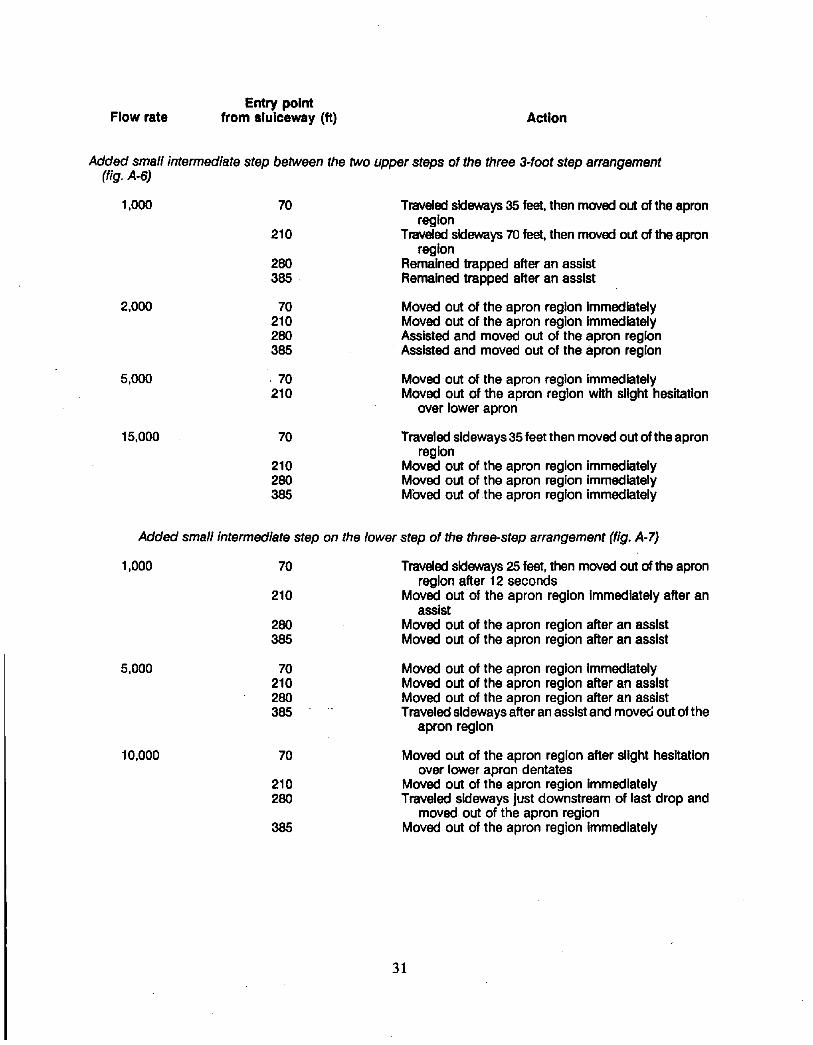
Added small intermediate step between the two upper steps of the three 3-foot step arrangement (fig. A-6)
1,000 70
210
280 385
Traveled sideways 35 feet, then moved out of the apron region
Traveled sideways 70 feet, then moved out of the apron region
Remained trapped after an assist Remained trapped after an assist
2,000 70 210 280 385
Moved out of the apron region Immediately Moved out of the apron region Immediately Assisted and moved out of the apron region Assisted and moved out of the apron region
5,000 , 70 210
Moved out of the apron region immediately Moved out of the apron region with slight hesitation
over lower apron
15,000 70
210 280 385
Traveled sideways 35 feet then moved out of the apron region
Moved out of the apron region Immediately Moved out of the apron region immediately Moved out of the apron region immediately
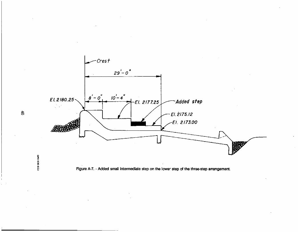
Added small intermediate step on the lower step of the three-step arrangement (fig. A-7)
1,000 70
210
280 385
Traveled sideways 25 feet, then moved out of the apron region after 12 seconds
Moved out of the apron region Immediately after an assist
Moved out of the apron region after an assist Moved out of the apron region after an assist
5,000 70 210 280 385
Moved out of the apron region Immediately Moved out of the apron region after an assist Moved out of the apron region after an assist Traveled sideways after an assist and movec; out of the
apron region
10,000 70
210 280
385
Moved out of the apron region after slight hesitation over lower apron dentates
Moved out of the apron region immediately Traveled sideways Just downstream of last drop and
moved out of the apron region Moved out of the apron .region Immediately
31

Flow rate Entry point
from sluiceway (ft) Action
1,000
2,000
5,000
10,000
15,000
Four short l-foot steps and one 3.25-foot stepup to crest (fig. 7)
70
210
280
385
Moved out of the apron region Immediately after an assist
Moved out of the apron region Immediately after an assist
Moved out of the apron region Immediately after an assist
Moved out of the apron reglon Immediately after an asslst
70
,70
210 280 385
When going over prow, first caught on comer of block, detached itself, and moved out of the apron region
When going over the weir parallel to the crest, an assist was needed, then spun sideways, and moved out of the apron region
Moved out of the apron region Immediately Tumbled sideways and moved out of the apron region Moved out of the apron region after an assist
70
7O 210
220 280 385
70
O
210 280
Traveled sideways 35 feet between lower apron dentates and roller on the lower apron, then moved out of the apron region
Moved out. of the apron region Immediately Traveled sideways upstream of roller on lower
apron, then moved out of the apron region Moved out of the apron region Immediately Moved out of the apron region immediately Moved out of the apron region with slight hesitation
Going over prow, first kayaks moved out of the apron region Immediately
Going over crest sideways, kayak traveled sideways about 15 feet, then moved out of the apron region
Moved out of the apron region Immediately Traveled sideways 175 feet, then trapped In foam
70
210 280
.385
Violently spun and traveled sideways 305 feet, trapped in foam
Traveled sideways 175 feet, then trapped in foam Traveled sideways 105, then trapped In foam Trapped in foam
32

Entry point Flow rate from sluiceway (ft) Action
Four different length lofoot steps downstream from the top 3.25-foot step, last step extending to 32 feet from crest -
r e c o m m e n d e d design (fig. 8)
1,000 70 210
280 385
Assisted, then moved out of the apron region Assisted, traveled sideways 20 feet, then moved out
of the apron region Hesitated slightly, then moved out of the apron region Assisted, then Moved out of the apron region
2,000 70 210
280 385
410
Moved out of the apron region immediately Traveled sideways 15 feet, then moved out of the apron
region Moved out of the apron region immediately Assisted and either moved out of the apron region
Immediately or was trapped depending on slight distance differences from sluiceway
Trapped on diagonal line of dentates
5,000 70 210 280
385
Moved out of the apron region immediately Movedout of the apron region immediately Hesitated over lower apron slightly, then Moved out
of the apron region Assisted, then moved out of the apron region
Immediately
10;000 70
210 280 385
• Traveled sideways 70 feet downstream of roller upstream of the lower dentates, then moved out of the apron region
Moved out of the apron region Immediately Moved out ,of the apron region Immediately Trapped 45 seconds, traveled sideways 20 feet, and
moved out of the apron region
1:5,000
20;000
70
210 280 385 70
210 280 385
Traveled sideways 35 feet, then Moved out of the apron region
Moved out of the apron region immediately Moved out of the apron region immediately Moved out of the apron region Immediately Kayak spun sideways, traveled sideways 35 feet
in 6 seconds, then moved out of the apron region Moved out of the apron region immediately Moved out of the apron region immediately Moved out of the apron region immediately
38,000 70 210
.280
385
,Moved out of the apron region immediately Traveled sideways 35 feet, then moved out of the apron
;region Traveled sideways 35 feet, then moved out of the apron
region Temporarily trapped in the region bounded by the
diagonal line of dentates
33 J

El. 2180. 2.5 ~ E/. 2176. O0
Figure A-1. - Lower upper apron block only.

t ~
# #
EL 2 1 8 0 . 2 5 ~ I 13 - 9 .. j
El. 2176.00
Figure A-2. - Stacked b~ocks on upper apron, long block on lower apron.
t ~
••-Crest , 32
El. 2180.25., I- ,_ ,, =-
( / ~ - El. 2176.00 El ~ El. ,2179.00
2173.00
Figure A-3. - Stacked blocks on upper apron with short block on long block covering lower apron dentates.

- 4
/fCrest 32' -]
\~ - ~ f E ~ . 2 1 7 9 . o o I __ _ _ ~ . ~ ~ F E ' " '?" ' 7 6 " 0 0
El 2.173.00
Figure A-4. - Stacked blocks on upper apron with short top block covering upper apron dentates.

O0
f C r e s t , .
• 2 9 - 0
E 8' O" ' " - I 0 - 4
- E l . 2 1 7 7 . 2 5
/ - E I . 2 1 7 5 . 1 2
f EI. 2173.00
Figure Ao5. - Three steps, one 3 feet high starting at crest elevation and two 2.12-foot steps.

El. 2 1 8 0 . 2 5
2 9 ' - 0 "
I I I I I I
8 - 0 , 1 0 - 4 dded step
21 - - El. 2 1 7 5 . 1 2
f f - -EI . 2173.00
Figure A-6. - Added small Intermediate step between the two upper steps on the three 3-foot step arrangement.
EL ~.
~f--Cresf
I #
29 - 0
I II I n I0 - 4
v
/ ~ E I . 2177.25 ~ A d d e d sPep
E/. 2/75.12 El. 2.173.00
Figure A-7. - Added small intermediate step on the lower step of the three-step arrangement.
Mission of the Bureau of Reclamation
The Bureau of Reclamation of the U.S. Department of the Interior is responsible for the development and conservation of the Nation's water resources in the Western United States.
The Bureau's original purpose "to provide for the reclamation of arid and semiarid lands in the West' today covers a wide range of interrelated functions. These include providing municipal and industrial water supplies; hydroelectric power generation; irrigation water for agriculture; water quafity improvement; flood control; river navigation; river regulation and control; fish and wildlife enhancement; outdoor recreation; and research on water-related design, construction, materials, atmospheric management, and wind and solar power.
Bureau programs most frequently are the result of close cooperation with the U.S. Congress, other Federal agencies, States, local governments, academic institutions, water-user organizations, and other concerned groups.
A free pamphlet Is available from the Bureau entitled "Publications for Sale." It describes some of the technical publicatlons currently available, thelr cost, and how to order them. The pamphlet can be obtained upon request from the Bureau of Reclamation, Attn D-7923A, PO Box 25007, Denver Federal Center, Denver CO 80225-0007.