model selection & design manual
TRANSCRIPT
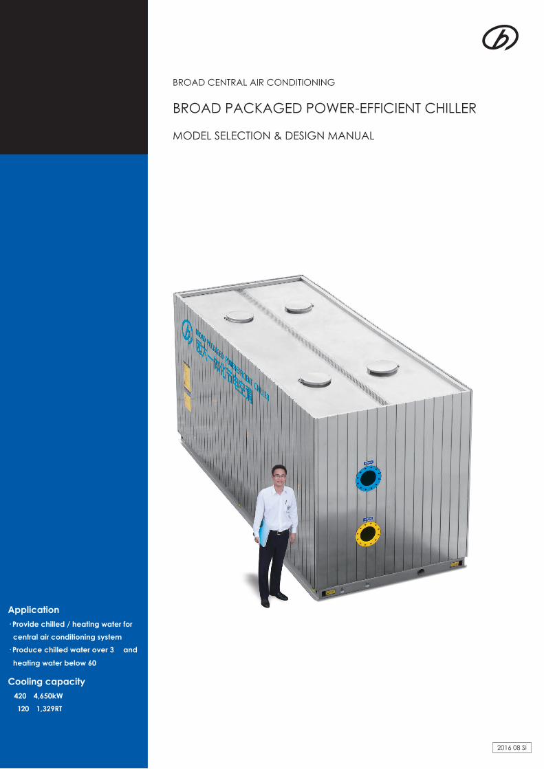
BROAD PACKAGED POWER-EFFICIENT CHILLER
MODEL SELECTION & DESIGN MANUAL
BROAD CENTRAL AIR CONDITIONING
2016 08 SI
Application· Provide chilled / heating water for
central air conditioning system· Produce chilled water over 3℃ and
heating water below 60℃
Cooling capacity 420~4,650kW (120~1,329RT)

(CY90 Packaged Chiller)
Global internet monitoring system for BROAD users since 1996
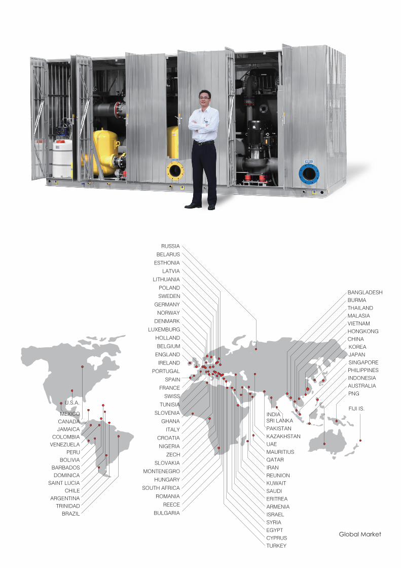
Global Market

VALUES OF BROAD POWER-EFFICIENT CHILLER
ENERGY SAVINGThe Integrated Part Load Value (IPLV) of the chiller can reach 11. This high IPLV can reduce energy consumption by 40% when compared to traditional electric chillersA BROAD Packaged Water Distribution System can reduces electricity consumption up to 76% when
compared to conventional field-built systems
ADDITIONAL COST SAVINGSThe magnetic oil free and zero friction technology can save up to 40% energy cost and 90% of maintenance cost when compared with traditional electric chillers. BROAD PLC “Smart anti-surge control” module insures the chiller always operate in a safe range. The integrated design of the BROAD chiller, water distribution system and stainless steel metal
enclosure reduce design cost and field installation costs for customers
SPACE SAVING Compared with the traditional electric chillers, A BROAD chiller package reduces volume by 30~50% and the weight by 30%BROAD Packaged Water Distribution System and stainless steel metal enclosures can be installed outside
which reduces mechanical room footprint requirements
WORRY-FREEBROAD Packaged Water Distribution System and stainless steel metal enclosure eliminate risk and reduce system design, procurement and installation errorsBROAD Intelligent Control System (ICS) can be automated for operator free operation of the chiller and water distribution system. BROAD Global Internet Monitoring System provides customers with 24/7/365 fault prediction, analysis and energy-saving management tools
AS THE GLOBAL LEADER OF NON-ELECTRIC CHILLER, WHY BROAD ALSO MAKES ELECTRIC CHILLER?
The BROAD non-electric chiller is the world’s most efficient method to produce chilled water when evaluating original source “primary energy fuels”. A BROAD Direct Fired Absorption Chiller/Heater is able to generate chilled, heating and domestic hot water simultaneously. These three outputs from a single absorption unit is the most reliable system when looking at potential points of failure. The BROAD Generation XI Absorption Chiller provides the longest life span and the quietest operation available in the market today.With the emergence of growing CHP, wind and solar PV power systems we are now manufacturing the power-efficient chiller.Markets for the new power-efficient chiller are as follows:1. Locations of the developing world where there is no access to natural gas or waste energy sources2. Applications for small cooling only requirements3. Site specific locations powered by only wind, hydro or solar PV has great potential to reduce CO2 emissions4. A BROAD Power-efficient Chiller is more efficient than traditional electric chillers5. A BROAD Packaged Water Distribution System is more efficient than traditional distribution systems6. A BROAD Power-efficient Chiller can be combined with a BROAD CHP system, which has higher
efficiency and energy flexibility than a non-hybrid or single energy source plant

CONTENTS
Power-efficient Chiller 1
8
Working Principle
Power-efficient Chiller Cooling Performance Data
Power-efficient Chiller General Conditions
Packaged Power-efficient Chiller Performance Data
Power-efficient Heat Pump Performance Data
Performance Curves
Model Selection Curves
Nomenclature
Combination of Non-electric Power-efficient Chillers
Model Selection & Ordering
Supply Scope
1
3
3
3
3
4
4
4
5
6
7
Dimensions
P&I Diagram
Control System Diagram
Exterior Wiring Diagram
List of Control System Site Engneering
Scope of Supply/Work
Machine Room Construction Tips
Transportation Tips
Lifiting & Leveling Tips
8
11
12
13
14
15
16
16
17
Design & Construction Tips

1
12℃
7℃
magnetic bearing compressor
water d
istribution systemcooling tow
er
water softener
city water
chilled W
. pump
cooling W. pum
p
pumpset
chiller
auto dosing
chilled water
evaporator
throttle valve
condenser
The compressor compresses 7℃ low-temp. & low-pressure refrigerant vapor to 45℃ high temp. & high pressure vapor
then flows into condenser. In condenser cooling water absorbs the heat from refrigerant vapor condensation process
and its temperature raises from 30℃ to 35℃. Then the heat will be discharged to air through cooling tower. After
condensation, 33℃ refrigerant becomes into 6℃ low-temp. & low-pressure liquid after throttle valve. The refrigerant
enters evaporator and evaporates immediately. It absorbs heat from the chilled water and makes chilled water drop
from 12℃ to 7℃. After evaporation, the refrigerant gasifies into 7℃ vapor and sucked into compressor. Then next
cycle begins
The cooling principle
mid-temp. & high-pressure refrigerant
low-temp. & low-pressure refrigerant
low-temp. & low-pressure refrigerant vapor
chilled water
high-temp. & high-pressure refrigerant vapor
cooling water
BROAD Packaged Power-efficient Chiller
2
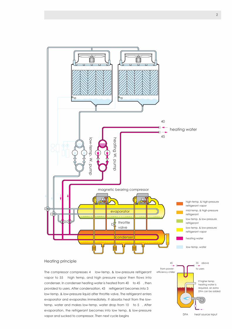
heating water
40℃
45℃
condenser
evaporator
throttle valve
heating W. pum
p
low-tem
p. W. pum
p
magnetic bearing compressor
The compressor compresses 4℃ low-temp. & low-pressure refrigerant
vapor to 55℃ high temp. and high pressure vapor then flows into
condenser. In condenser heating water is heated from 40℃ to 45℃, then
provided to users. After condensation, 43℃ refrigerant becomes into 3℃
low-temp. & low-pressure liquid after throttle valve. The refrigerant enters
evaporator and evaporates immediately. It absorbs heat from the low-
temp. water and makes low-temp. water drop from 10℃ to 5℃. After
evaporation, the refrigerant becomes into low temp. & low-pressure
vapor and sucked to compressor. Then next cycle begins
Heating principle
mid-temp. & high-pressure refrigerant
low-temp. & low-pressure refrigerant
low-temp. & low-pressure refrigerant vapor
heating water
high-temp. & high-pressure refrigerant vapor
low-temp. water
heat source inputDFA
45℃ 55℃ above
from power-efficiency chiller
If higher temp. heating water is required, an extra DFA can be added
to users

3
Mode CY 35 90 180 400
Cooling capacity kW 420 1045 2090 4650
Pump
set
Chilled water pump
External head mH2O 18 20 20 20
Power demand kW 8 22 44 90
Cooling water pump
External head mH2O 10 9 9 9
Power demand kW 6 15 37 60
Total power
demand
kW 14 37 81 150
Shipment wt. kg 2000 2600 5400 8000
Operation wt. kg 3000 3900 7000 10000
Power demand kW 5.5 11 15 37
Operation wt. kg 2960 7600 14300 28700
Power-efficient Chiller Cooling Performance Data
Packaged Power-efficient Chiller Performance Data
General Conditions
Mode C 35 90 180 400
Cooling capacity kW 420 1045 2090 4650
104kcal/h 36 90 180 400
RT 120 300 600 1329
Power demand kW 74 169 327 720
Rated COP 5.70 6.20 6.40 6.46
COP(IPLV) 9.32 10.6 10.7 11.5
Starting current A A 2 4 8 8
Maximum operation current
A 160 360 740 1500
Evaporator
Flow rate m3/h 72 180 360 800
Pressure drop kPa 40 65 65 75
Connection diameter DN 150 200 250 350
Condenser
Flow rate m3/h 90 225 450 1000
Pressure drop kPa 30 60 60 70
Connection diameter DN 150 200 300 400
Refrigerant wt. kg 260 550 1100 2000
Shipment wt. kg 2800 4800 9600 16500
Operation wt. kg 3200 5400 10800 18500
Power-efficient Heat Pump Performance Data
Notes:
1. Rated low temp. heating W. outlet/inlet temp:15/20℃
2. Rated A/C heating W. outlet/inlet temp.: 45/40℃
(Highest permitted outlet temp. 60℃)
3. Please contact BROAD for solution for non-rated conditions
Model C35-R
Heating capacity 628kW
Power demand 110kW
Rated COP 5.71
Starting current 2A
Maximum operation current 190A
Maximum input power 115kW
Evaporator
Flow rate 72m3/h
Pressure drop 40kPa
Connection diameter DN150
Condenser
Flow rate 108m3/h
Pressure drop 40kPa
Connection diameter DN150
Refrigerant 260kg
1. Rated chilled W. outlet/inlet temp:7/12℃
2. Rated cooling W. outlet/inlet temp:35/30℃
3. Lowest permitted outlet temp. for chilled
water:3℃
4. Lowest permitted inlet temp. for cooling
water:10℃
5. Adjustable chilled water flowrate:30~120%
6. Adjustable cooling water flowrate:20~140%
7. Pressure limit for chilled W. and cooling W.:
≤1.0MPa (high pressure model available)
8. Adjustable load:10~100%
9. Fouling factor for chilled W:0.018m2· K/kW
Fouling factor for cooling W:0.044m2· K/kW
10. Refrigerant:R134a
11. Machine room ambient temperature:
5~43℃,humidity ≤85%
12. Life design: 30 years
13. Operation noise:≤65dB(A)
14. Operation vibration:≤0.30mm

4
Notes: Calculation method of COP
COP= cooling capacity%/electricity consumption%×rated COP
e.g.C90 rated COP is 6.2,chilled water temp. is 7℃ ,cooling
water temp. is 26℃ ,then cooling capacity is 100%, electricity
consumption is 87%, COP=100%/87%×6.2=7.12
Nomenclature
Codes for high pressure type:
Codes for power supply:
Pressure limit
MPa
Chilled
W.
Cooling
W.1.01~1.60 Fb Mb1.61~2.00 Fc Mc2.01~2.40 Fd Md
Power
supply
Voltage Frequency
B1 380V 50HzB2 400~415V B3 460V 60HzB5 380VB6 400~415V B7 575V
C Y 35 A - 35/29 - 6/14 - B3 - R - Fb
High pressure type(details in right table)
Function: R Heat pump type
Power Supply(3phase 460V/60HZ)
(details in right table)
Chilled W. outlet/inlet temp.(ignored for
rated condition)
Cooling W. outlet/inlet temp.(ignored for
rated condition)
Product design serial number
Cooling capacity:104kcal/h
Y: Packaged chiller (including pumpset,
metal enclosure)
C:Magnetic bearing type
Performance Curves Model Selection Curves
Cooling water temp. changes
Cooling water inlet temp. ℃
%
%
Chilled water outlet temp. ℃
Chilled water temp. changes
Cooling capacity changes
Cooling capacity %
Cooling capacity
Electricity consumption
53 7 9 11 13 15 1770
80
202010
60
40
40 50 60 70 80 90 10030
80
100
90
100
110
120
130
70
60
80
90
100
110
120
19
20 22 24 26 28 30 32 34 36
Electricity consumption %
20
30
40
50
60
70
80
90
100
110
120
Cooling water temp.℃
Chilled water temp.℃130
30
40
50
70
60
80
90
100
110
12018 20 22 24 26 28 30 32 34 36
18℃
15℃
13℃
11℃
9℃
7℃
5℃
3℃
18℃15℃13℃11℃9℃7℃5℃3℃
Cooling capacity %
Electricity consumption %

5
Combination of Non-electric Chiller and Power-efficient Chiller
Energy self-sufficient system
Combination of CHP and power-efficient chiller
Exhaust
500℃ Exhaust chiller
Power-efficiency chillerElectricity
NG
Cooling
Electricity
NG Heating
Gas turbine
Most applicable to places
with huge heating and
cooling load difference
Combination of vacuum boiler and power-efficient chiller
Vacuum boiler
Power-efficiency chiller
NG
Electricity
Heating
Cooling
NG
Daily shift or seasonal shift
according to different
energy prices
Combination of direct-fired chiller and power-efficient chiller
Direct-fired chiller
Power-efficiency chiller
NG
Cooling
Electricity
HeatingNG
Waste heat is priority
power-efficient chiller used
as supplementary
Combination of waste heat chiller and power-efficient chiller
Waste-energy chiller
Power-efficiency chiller
Cooling
Electricity
HeatingWaste hot waterExhaustWaste steam

6
Model Selection & Ordering
Function selection· Cooling only type
· Heat pump type
· Combination of CHP and power-efficient chiller,
Combination of waste heat chiller and power-
efficient chiller, Combination of direct-fired chiller
and power-efficient chiller, Combination of vacuum
boiler and power-efficient chiller
Load selection· Any building cooling load cannot be estimated
according to the building area, as it is more closely
related to building insulation and room function.
· 30~50W/m2 is recommended for energy-efficiency
building, 60~90W/m2 for normal building, 100~150W/m2
for high occupant density and high space building
Flowrate selection· BROAD designs the distr ibution system head
according to its profound experiences
· BROAD is open for special head design
Pressure selection· The standard pressure limit for chilled/heating/cooling
water is 1.0MPa. Information about high pressure type
please see Code for high pressure type· >2.0MPa system: secondary heat exchange
recommended
Control· BROAD power-efficient chillers are equipped with
complete control function including internet monitoring
· If users have a building management system(BMS),
the BMS control interface can be selected as an
optional supply. If the BMS interface is not ordered
along with the chiller, it can be purchased later
· BROAD BMS is recommended to customers (for the
whole building)
Machine room location· On the floor or on building rooftop
· chiller can also be installed in the basement
· Cooling tower should be installed on the floor, on
stilt or on building rooftop
Packaged selection· Packaged power-efficient chiller includes chiller,
water distribution system, metal enclosure as
machine room, etc.
· If the packaged system is installed in the building,
metal enclosure can be selected as an option
· Cooling tower is an option for international
Lead time· ≤CY90: 4 months
· ≥CY180: 6 months
Warranty Free warranty is to cover 12 months from commissioning
or 18 months from shipment,whichever comes earlier
Technical specification is based upon· GB 25131 Safety Requirements For Water Chillers
(Heat Pump) Using The Vapor Compression Cycle
· GB 19577 Minimum Allowable Values Of Energy Efficiency
And Energy Efficiency Grades For Water Chillers
· ANSI/AHRI 551-591(SI) with Addendum Performance
Rating of Water-Chilling and Heat Pump Water-Heating
Packages Using the Vapor Compression Cycle
· GB/T18430 Water Chilling(Heat Pump) Packages
Using The Vapor Compression Cycle. Part 1: Water
Chilling(Heat Pump) Packages For Industrial &
Commercial And Similar Application
· GB/T 19409 Water-Source (Ground-Source) Heat Pumps
7
Supply Scope
Products Category Item Remarks
Chiller Chiller Heat exchanger Include condenser, evaporator (cold insulation included)
Compressor Magnetic bearing, VFD centrifugal type ,oil free operation
Throttling set Include electronic expansion valve, drying filter, shut-off valve, regulating valve
Check valve Prevent refrigerant vapor flow-back to protect compressor
Motor cooling device Include drying filter, control valve set etc
Control system
Low voltage control cabinet Include low voltage electric parts, control board, PLC, etc
Power control cabinet Includes switch gear, instant, reactor etc
Touch screen For operation
External control elements Include temperature & pressure sensors, flow switches, solution level probes and actuators
BMS interface (optional) Connect to BMS system through dry contact or serial communication
Refrigerant R134a Used for cooling or heating
Pumpsetsystem
Pumpset A/C water pump Two units
Cooling water pump Two units
Accessories Include zero resistance filter, check valve, soft connectors, valves and vibration isolator etc
Piping * Include all piping between pumpset and chiller
Piping accessories Include flow switches, auto air vent & its socket, soft connectors
Motor drain valve When water quality becomes poor, this valve automatically drains the cooling water. It also drains cooling water automatically in winter to avoid freeze
A/C W. flowmeter For precise management of chiller load and efficiency
Water softener Improve A/C water and cooling water quality
Auto dosing device Automatically charge biocide corrosion inhibitor and anti-sludge to the cooling water
Pumpset control cabinet Include inverters for A/C W. pump, cooling W. pump, cooling fan soft starter, low voltage electric parts, etc
Electric wiring * Include wires, cables, cable conduit, cable supporters, etc.
Cooling tower (option)
Cooling tower Include auto water makeup device, spraying device, anti-drifting device, fillings, water makeup and draining pipe /valve
Cooling tower fan Cooling fan cable & control wiring not included
Option Enclosure Enclosure Include stainless steel panel, roof cover, structural frame, baseframe, as well as accessories
Notes:1. * only for standard size. Special offer is available
2. If the customer does not order cooling tower, only linkage control signal to cooling fan will be. provided
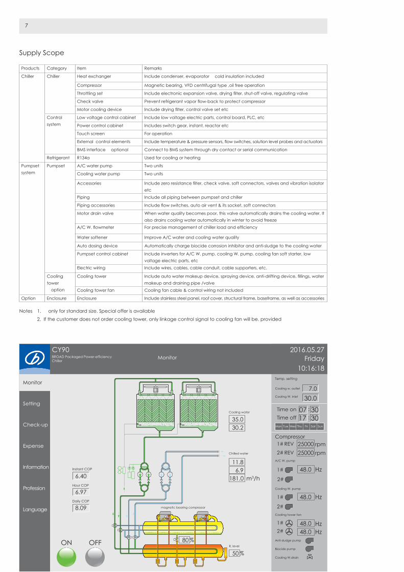
CY90BROAD Packaged Power-efficiency Chiller
2016.05.27Friday
10:16:18
Time on
Temp. setting
A/C W. pump
Compressor
Cooling W. pump
Cooling tower fan
Anti-sludge pump
Biocide pump
Cooling W.drain
Cooling w. outlet
Chilled water
48.0 Hz
48.0 Hz
HzHz
48.048.0
℃6.9
℃7.0℃30.0
℃11.8
6.40
6.97
8.09
m3/h181.0
R. level
%80
%50
REV rpm25000
Cooling W. inlet
Instant COP
Hour COP
Daily COP
Cooling water
℃35.0℃30.2
Time off
1#
1#
1#2#
2#
1#
REV rpm250002#
2#
Mon Tue Wed Thu Fri Sat Sun
07 303017
Monitor
Monitor
Setting
Check-up
Expense
Information
Profession
Language
ON OFF
magnetic bearing compressor
8DESIGN & CONSTRUCTION TIPS
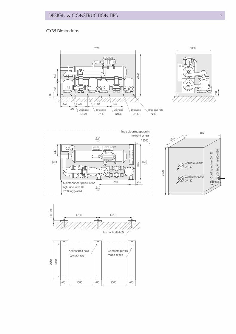
CY35 Dimensions
3960 1880
1880
3960
565
200
Control cabinet
Strong current cabinet
Cont
rol c
abine
t for
wat
er
distr
ibut
ion
syste
m
Left
Right
Maintenance space in the
Tube cleaning space in the front or rear
≥2000
Anchor bolt6-M24
Anchor bolt hole Concrete plinths made at site120×120×400
Chilled W. outletDN150
Chi
lled
W. in
letD
N150
Coo
ling
W. in
letD
N150
Cooling W. outletDN150
right and left≥800,1200 suggested
Front Rear
DN25Drainage DrainageDrainageDrainage
DN25
1780 1780
400 1380 1380400 400
2351690
DN40 DN40Dragging hole
Φ50
660 1140 745
2200
1880
2200
655
780
640
2080
100~
200
1840
380
100
9
CY90 Dimensions
5520 2130
2130
5520
1425200
Control cabinet
Strong current cabinet
Strong current cabinet
Contr
ol ca
binet
for w
ater
distrib
ution
syste
m
Left
RightMaintenance space in
Tube cleaning space in the front or rear≥4000
Anchor bolt6-M24
Anchor bolt hole Concrete plinths made at site120×120×400
Chilled W. outlet DN200
Chi
lled
W. in
let D
N200
Coo
ling
W. o
utle
tDN2
00
Cooling W. outlet DN200
the right and left≥800, 1200 suggested
DN25Drainage DrainageDrainageDrainage
DN25
2560 2560
400 2160 2160400 400
2502390
DN40 DN40Dragging hole
Φ50
660 1500 940
2130
2500
775
810
700
2330
100 ~
200
2090
380
100
2500
RearFront

10
Cooling W. outlet L
Cooling W. inlet L
Chilled W. inlet KSplit lifting is available
A
EG
F
a d
BC
D
100
≥NChilled W. outlet K
H I
DN25 DN40Dragging hole
Φ50
Tube cleaning space in the rear
≥JRight
Left
e e f f400
400 400 400800 400b b c c
FrontRear
Maintenance space in the front≥4000
Maintenance space in the right and left
Control cabinet
Strong current cabinet
Strong current cabinet
Strong current cabinet
Strong current cabinet
Anchor bolt 12-M24
100~
200
Anchor bolt hole Concrete plinths made at site120×120×400
Drainage Drainage
CY180、CY400Dimensions
Mode A B C D E F G H I J
CY180 10210 2130 2500 590 1510 300 1545 2885 820 4000
CY400 11410 2140 3000 625 1975 600 1000 2280 1095 5000
Mode K L M N a b c d e f
CY180 DN250 DN300 1600 1200 2330 2090 1765 2090 2490 2165
CY400 DN350 DN400 2000 1200 2360 2480 2025 2100 2880 2425

11
P&I Diagram
PM PMF4 F3F5
T2
T1
B1
T4
T3
B2
P1
YKP2
F6F7
F4 F3F5
F6F7
F1 F1EXV
G F2 G F2
TS
KFEKD
G F2
F2
F2
LBV LBV
F9
FE
YE YF
F8
S
city water
chilled water
pumpset control cabinet
PLC control cabinet
internet
F8 F8
YDYD
YAYAYB
YC YC INV1INV2
cooling W. pum
p
chilled W
. pump
auto dosing d
evice
water softener
F8
V F
YCYE YF
YC
FE
F9 F9 F9LQFJ LQFJ
Control devices:
EKDINV1INV2PLCTS
Controlled objects:
EXVKFLBVLQFJPMYB
Sensors:
T1T2T3T4B1B2P1P2SV
Others:
F1F2F3F4F5F6F7F8F9FEYAYCYDYEYFYKG
electronic throttle valve controller
cooling tower fan inverter
cooling water pump inverter
Programmable Logic Controller
TS touch screen
electronic throttle valve
control cabinet fan
load balancing valve
cooling tower fan
compressor
motor drain valve
chilled W. inlet temp. sensor
chilled W. outlet temp. sensor
cooling W. inlet temp. sensor
cooling W. outlet temp. sensor
chilled W. flow switch
cooling W. flow switch
evaporation pressure sensor
condensation pressure sensor
conductivity sensor
A/C W. flowmeter
check valve
shutoff valve
safety valve
purge valve
vent valve
drain valve
refrigerant discharge valve
shutoff valve
balance valve
auto water makeup valve
auto vent valve
manual drain valve
pollution discharge valve
water makeup valve
manual water makeup valve
level probe
dry filter
Notes:1.Chiller scope 2.Line type: actuator signal output
sensor signal input
communication
12
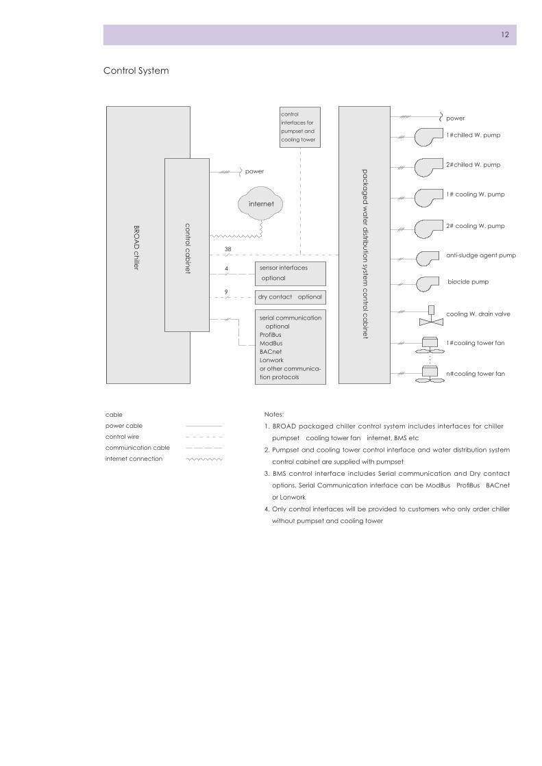
Control System
Notes:
1. BROAD packaged chiller control system includes interfaces for chiller、
pumpset、cooling tower fan、internet, BMS etc
2. Pumpset and cooling tower control interface and water distribution system
control cabinet are supplied with pumpset
3. BMS control interface includes Serial communication and Dry contact
options. Serial Communication interface can be ModBus、ProfiBus、BACnet
or Lonwork
4. Only control interfaces will be provided to customers who only order chiller
without pumpset and cooling tower
cable:
power cable
control wire
communication cable
internet connection
BROA
D chiller
packaged w
ater distribution system
control cabinet
control cabinet
control interfaces for pumpset and cooling tower
power
internet
sensor interfaces
power
1#chilled W. pump
1# cooling W. pump
2# cooling W. pump
anti-sludge agent pump
biocide pump
cooling W. drain valve
1#cooling tower fan
n#cooling tower fan
2#chilled W. pump
dry contact(optional)
serial communication(optional)ProfiBusModBusBACnetLonwork or other communica-tion protocols
38
4
9
(optional)
13
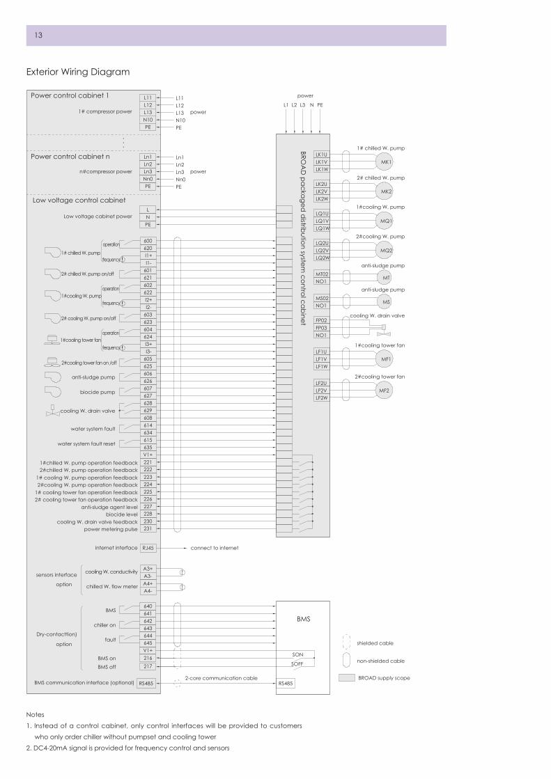
Power control cabinet 1
1# compressor power power
power
power
L11L12L13N10PE
L11L1 L2 L3 N PEL12
L13N10PE
Ln1 LK1ULK1V MK1
MK2
MQ1
MQ2
MT
MS
MF1
MF2
LK1W
LQ1ULQ1VLQ1W
LF1ULF1VLF1W
LF2ULF2VLF2W
LQ2ULQ2V
MT02NO1
MS02NO1
FP03FP02
NO1
LQ2W
LK2ULK2VLK2W
Ln2Ln3Nn0PE
Ln1Ln2Ln3Nn0PE
LNPE
600620
601621602622 I2+ I2-
I1+ I1-
603623604624 I3+ I3-605625606626607627628629608614634615635V1+221
n#compressor power
Low voltage cabinet power
1# chilled W. pump
1#chilled W. pump operation feedback2222#chilled W. pump operation feedback
V1+216217
RS485 RS485
SON
SOFF
2231# cooling W. pump operation feedback2242#cooling W. pump operation feedback2251# cooling tower fan operation feedback2262# cooling tower fan operation feedback227anti-sludge agent level228biocide level230cooling W. drain valve feedback
1# chilled W. pump
2# chilled W. pump
1#cooling W. pump
2#cooling W. pump
anti-sludge pump
anti-sludge pump
cooling W. drain valve
1#cooling tower fan
2#cooling tower fan
231 power metering pulse
RJ45internet interface
BMS communication interface (optional)2-core communication cable
shielded cable
non-shielded cable
BROAD supply scope
connect to internet
sensors interface
(option)
Dry-contacttion)
(option)
A3+A3-
cooling W. conductivity
A4+A4-
chilled W. flow meter
640641BMS
642643chiller on
644645fault
BMS onBMS off
2# chilled W. pump on/off
2# cooling W. pump on/off
2#cooling tower fan on /off
anti-sludge pump
biocide pump
cooling W. drain valve
water system fault
water system fault reset
1#cooling W. pump
1#cooling tower fan
operation
frequency
operation
frequency
operation
frequency
Power control cabinet n
Low voltage control cabinet
BMS
BROA
D packaged
distribution system
control cabinet
Exterior Wiring Diagram
Notes:
1. Instead of a control cabinet, only control interfaces will be provided to customers
who only order chiller without pumpset and cooling tower
2. DC4-20mA signal is provided for frequency control and sensors

14
Item Object Installation position
and requirement
Material Source BROAD scope Customer scope
chiller Chiller power Chiller control cabinet
and water system
5-core cable Customer / Cable installation
and wiring inside
chiller control
cabinet
Touch screen Built-in / BROAD / /
Ambient temperature
sensor
Ventilation and avoid
direct sunlight
3-core shielded
cable(10m standard
supple)
BROAD Wiring inside
chiller control
cabinet
Temperature sensor
installation and
cable installation
Network monitor Built-in Network cable Customer Wiring inside
chiller control
cabinet
Cable installation
Wiring at building
side
BMS
interface(optional)
Chiller control cabinet Communication
cable(for serial
communication), 11-
core cable(for dry
contact)
Customer Wiring inside
chiller control
cabinet
Cable installation
wiring at building
side
Chiller and pumpset
grounding
Grounding resistance
≤4Ω
Grounding
wire
Customer / Grounding setup
and wiring
pumpset Main power supply
connection
Water distribution
system control cabinet
5-core cable Customer Wiring inside
chiller control
cabinet
Cable installation
Wire between chiller
and water distribution
system cabinet
Between chiller and
water distribution
system cabinet
Cable supply as per
package chiller
BROAD installation and
wiring inside
chiller control
cabinet
/
List of Control System Installation

15
Scope of Supply/Work
Category Item BROAD Customer Remarks
Transportation &
Location
Factory to port √ BROAD can arrange transportation upon request
Jobsite settlement(eg. erection) √ BROAD provides free guidance
Electric engineering Power supply to enclosure √ 3 phase, 4 wires
Internet connection √ Network cable to the enclosure is to be provided by
customer
Grounding √
Construction & Instal-
lation
Foundation √
Pipe connection between chiller
and pumpset for order with
pumpset
√ A crane must be provided by customer
External piping installation √ Include chilled water pipes, water make-up and
drain pipes
Chiller insulation and chilled water
pumps insulation
√ Factory-mounted
Piping insulation in enclosure √ For order with pumpset
Pipeline insulation √
Anti-freezing √ Water anti-freeze treatment is recommended when
the ambient temp. is below 0℃
Commissioning Jobsite chiller commissioning √ Customer provides energy and air conditioning load
Operation & Mainte-
nance
Operator training on site √ BROAD provides free professional site training;
the customer pays the accommodations and
transportation for BROAD engineer
Regular maintenance √ Service contract can be signed after the warranty
period
16
Machine Room Construction Transportation Tips
BROAD Packaged Power-exfficiency Chiller can be
placed outdoor directly, no additional construction of
machine room. Make the foundation in accordance
with the drawings
· Please refer to dimension drawings for plinth dimensions
· Load capacity:
①The machine room foundation load is recommended
as 1.5 times of the operation weight
②Make sure that the foundation is level without
sinking or overload(for rooftop installation)
③Chiller load should be evenly distributed on the
contact surface between the frame base rolling
steel and the plinth
· Anchor bolts:
①Anchor bolts must be pre-installed in foundation
per dimension drawings
②Place the chiller on the foundation directly and fix
it with anchor bolts
Machine Room Shipping Status
Foundation
Machine room built by customer
· Ventilation: poor ventilation leads to high humidity
in the machine room, which may erode the unit.
Please ventilate 3X machine rooms every hour
· Drainage:
①Chiller foundation must be on a high level in the
machine room
②All discharge pipes and drainpipes must be visible
above the drainage
③Machine room in basement must be built above a
water ditch, which is equipped with an auto level-
controlled submerged pump
· Temperature:
machine room temperature must be controlled
within 5~43℃. Lower temperature may crack heat
exchange tubes and water box when the chiller is
shut off. Higher temperature may damage electrical
components. Thermometer and over temperature
alarm must be installed in machine room
· Humidity:
machine room humidity must be lower than 85%. Higher
humidity may impair insulation of electrical components
· CY35 & CY90 are to be shipped in one piece, while
CY180 & CY400 in two pieces
· Al l equipment can be container ized as per
Container Arrangement Reference
· BROAD can arrange transportation and insurance
on behalf of customers. If customers manage it by
themselves, please refer to BROAD Chiller Packing &
Transportation Regulations for container arrangement
in advance, so as to make sure safety transportation

17
Lifting & Leveling Tips
Sketch of lifting
<90°
<90°<90°
<90°
<90°
1. Before the chiller is positioned, concrete foundation
plinths must be molded and leveled. The level degree
is <1.5‰, height of foundation is 100~200mm. Then fix
the chiller with anchor bolts on the foundation
2. Lifting must be done by qualified lifting companies
that are properly insured
3. The crane must be supported by crossties and
firm foundation to prevent it from sinking. Check
the crane steel ropes and hooks before lifting to
prevent any accident. The lifting intersection angle
must be less than 90°. It is strictly prohibited to lift
the chiller with a single steel rope. When the chiller
is lifted 20mm above the carriage or the ground, it
should be kept for a little while. Lift the chiller slowly if
everything is fine
4. If l imited by loading height, loading angle or
machine room access, the professional l ifting
company must make special plan with BROAD team
together to avoid any risk
5. The landing of the chiller must be with care. Crash
landing is strictly forbidden
6. When moving the chiller, only round steels or thick
steel tubes can be used as rollers instead of wooden
sticks. Only drag the dragging hole on the rolling
steel. Do not place forces on other part of the
chiller. Lift the unit first with jacks under the rolling
steel before rigging
7. After chiller positioning, please adjust leveling and
lay thin steel plate where it is uneven to guarantee
compact contact between the chiller and base.
Take tube sheet as the leveling point and make
front/rear and left/right leveling (check level height
of every part by acrylic tube). It should be leveled
within 1‰ both lengthwise and sidewise. Leveling
must be done within 2 hours after locating the chiller;
otherwise the chiller base will be damaged
8. The chiller must be located levelly and its steel frame
bases must match the plinth, the weight of the chiller
must be evenly balanced on the plinth
9. The chiller should be protected by full time personnel
during transportation & installation. No access
for unauthorized persons. Valves of the chiller are
forbidden to be screwed. If the machine room is
still under construction, precautions are essential to
avoid chiller get damaged or dirty. No scraping the
paint or insulation layer
CY35/90 Lifting sketch
CY180/400 Chiller lifting sketch CY180/400 Pumpset lifting sketch
Insert lift ropes after removing
the cover on chiller roof


BROAD power-efficient chillers and packaged water distribution system are ISO、
CE、ETL、ASME certified
To protect forest & water sources, please imitate us to adopt compact layout & thin paper printing
2016.09
The First Edition Quantity:10,000
BY290-16 © 2016
BROAD Town, Changsha, China 410138 www. broad.com
Tel: +86-731-84086688 Fax: +86-731-84610087
100g