model-rx-fl - aikoh the gauge within the allowable temperature range. if the gauge is used over or...
TRANSCRIPT

10
CPU GAUGE SWITCH FEELING
MODEL-RX-FL SERIES
Instruction Manual
Be sure to read through this instruction manual before using the product.
This instruction manual is very important for using the product properly.
Always keep it near the product and refer to it at any time whenever you need.
!
AIKOH ENGINEERING CO., LTD. [Tokyo Office] 14 -1 , 5 -Chome, Ueno , Ta ito -ku , Tokyo Tel: 03-5807-6434/Fax: 03-3834-2098[Nagoya Office] 210, 2-Chome, Sakuta, Nagakute, Aichi Tel: 0561-64-2331/Fax: 0561-64-2332[Osaka Office] 15-7, 2-Chome, Hishie, Higashi-osaka, Osaka Tel: 0729-66-9011/Fax: 0729-66-9017 Homepage address: http://www.aikoh.co.jp

1
INTRODUCTION
NOTES
*1: Load detecting sensor *2: Onward peak value (CP), onward bottom value (CL), return bottom value (RL),
return peak value (RP), click value (Cc), and click ratio (Cr)
- No part of this instruction manual may be reproduced in any form without permission. - This instruction manual is subject to change without notice. - This instruction manual is prepared with the greatest care. - In spite of this, please contact the shop you purchased this product or Aikoh's office or agent, if you
should find doubtful matters, omissions, etc.
05122005
AIKOH ENGINEERING CO.,LTD. INTRODUCTION
INTRODUCTION
Thank you for purchasing the CPU Gauge RX-FL Series.
The RX-FL Series is a digital push-pull gauge and has such features as: Converting analog data input from a load cell (*1) into digital data using an A/D converter, measuring the major values (*2) of switch feeling measurement, displaying the track values digitally, outputting data to external instruments, etc. Read through this instruction manual carefully and make full use of the RX-FL Series.
2
TABLE OF CONTENTS
INTRODUCTION······················································································ 1 SAFETY INSTRUCTIONS·········································································· 4 CHECKING CONTENTS ·········································································· 6 BEFORE USING PRODUCT······································································· 6 COMPONENT PARTS ··············································································· 7 FUNCTIONS OF COMPONENT PARTS······················································· 8 DISPLAY UNIT ························································································ 9
Special Display ········································································································· 9 SIMPLE OPERATION FLOWCHART··························································10
FUNCTION SETTING MODE····································································11 Option List and Flow of Selection ················································································11 Key Operation for Setting Options···············································································12 Validating/invalidating the comparator judgment function ··············································12 Setting the comparator judgment upper limit ································································12 Setting the comparator judgment lower limit ································································12 Selecting a main display option···················································································13 Selecting a sub display option ·····················································································13 Setting the trigger level ·····························································································14 Setting the width of data detection ··············································································14 Selecting overload external output···············································································14 Selecting the screen display direction···········································································14 Validating/invalidating the automatic power off function ·················································15 Validating/invalidating the automatic zero resetting function···········································15 Setting an RS-232C device ·························································································15 Adjusting the analog output to zero finely·····································································15 Setting the automatic entry time·················································································16
TRACK MODE·························································································16 Functions Available in Track Mode ··············································································16
FEELING MEASUREMENT MODE ···························································17 Functions Available in Feeling Measurement Mode ························································17 Detection Items········································································································17 Concept of Measurement····························································································18 Terms ·····················································································································18 Measurement Time Chart ··························································································19
CALIBRATION MODE··············································································20 Switching Calibration Points ······················································································20 Simple Calibration Example: RX-FL-1 (10 N) ································································21 About Calibration Points ···························································································24
AIKOH ENGINEERING CO.,LTD. TABLE OF CONTENTS

3
TABLE OF CONTENTS
DETAILS OF FUNCTIONS········································································25 Data Memory Function······························································································25 Automatic Power Off Function ····················································································25 Automatic Zero Resetting Function··············································································25 External Zero Resetting Function················································································26 External Contact Holding Function ·············································································26 Memory Data Display Function ··················································································27 Analog Output Function ····························································································27 Comparator Judgment Function ·················································································28 Overload External Output Function·············································································29 Printer Output Function····························································································29
REFERENCES ························································································30 About Data Communication ·······················································································30 Communication Command List ···················································································30 External Instruments and Output Data········································································31 Data Output Examples ······························································································32 Profile Drawing········································································································33 External I/O Connector Pin Assignment ·······································································34 Options···················································································································35
Optional cables ························································································································ 35 Measurement attachments ········································································································ 37 Printers ·································································································································· 38
Specifications···········································································································39
AIKOH ENGINEERING CO.,LTD. TABLE OF CONTENTS

4
SAFETY INSTRUCTIONS
This section describes the instructions important to ensure the safety. Be sure to observe these instructions. The symbols and their meanings are as shown below.
AIKOH ENGINEERING CO.,LTD. SAFETY INSTRUCTIONS
SAFETY INSTRUCTIONS
DANGER Indicates an urgent situation that is likely to result in death or serious injury of the user and/or enormous damages to the product depending on the structure, material or circumstances, if the instruction should be ignored and the product should be used improperly. WARNING Indicates an urgent situation that is likely to result in death or serious injury of the user, if the instruction should be ignored and the product should be used improperly. CAUTION Indicates an urgent situation that is likely to result in slight injury of the user, if the instruction should be ignored and the product should be used improperly.
DANGER
Do not recharge the battery for 24 hours or more.
If this instruction is disobeyed, the built-in battery may overheat excessively. Depending on circumstances, it may break, resulting in a fire.
Use the AC adapter supplied with the product. Do not use any other instrument.
If this instruction is disobeyed, a trouble may occur in the electric circuits or the like, resulting in a fire.
Recharge the battery or use the product on the specified voltage only.
Disobedience to this instruction may result in a fire, electric shocks or electrocution.
WARNING Be careful about scattering of test piece.
The test piece may scatter and cause injury. Pay great attention to the safety of the user and operation environments.
Do not use a flawed or deformed jig.
If a flawed or deformed jig is used, it may break or slip, resulting in injury. If a test piece drops onto your foot, it is very dangerous.
Connect the plug of the AC adapter with the AC outlet to the very end.
If the plug is connected loosely with the AC outlet, it may short-circuit, resulting in a fire, electric shocks or electrocution.

5
AIKOH ENGINEERING CO.,LTD. SAFETY INSTRUCTIONS
CAUTION Do not connect or disconnectthe AC adapter plug with a wet hand.
Disobedience to this instruction may result in electric shocks or electrocution.
Do not disconnect the plug of the AC adapter by pullingthe cable.
If this instruction is disobeyed, the cable may break, resulting in electric shocks or electrocution.
Never attempt to disassemble, repair or modify the product.
If you attempt to disassemble, repair or modify the product, it may malfunction, resulting in injury.
CAUTION Do not apply a load over the maximum measurement capacity.
If an excessive load is applied, the sensor may break. If a greater load is applied, the case or internal parts of the gauge may break, resulting in an accident.
Do not use or store the product in the environments shown on the right.
- Environment subject to spattering of water- Environment subject to dew condensation - Dusty environment - Environment subject to spattering of oil or chemicals
Use the gauge within the allowable temperature range.
If the gauge is used over or below the specified temperature range, it may malfunction. The guaranteed temperature range is from 5°C to 40°C.
Pay attention to the length of the set screws.
Use M-4 screws to install this gauge on another instrument. Make sure that the screws have 6-mm or shorter threads. Using screws with threads longer than 6 mm may damage the gauge case.
Do not apply a bending or twisting force to the load shaft.
Bending force Twisting force

6
CHECKING CONTENTS
BEFORE USING PRODUCT
AIKOH ENGINEERING CO.,LTD. CHECKING CONTENTS
CHECKING CONTENTS
Make sure that the following are supplied.
1. Gauge body (*1): 1 2. AC adapter (*2): 1 3. Warranty sheet: 1 4. Instruction manual (this book): 1 5. Measurement attachments (*3): 5
NOTES *1: Check the model of the product you purchased. *2: 100 VAC type -- Model-761
220 VAC type -- Model-762 (Export model) *3: Models 022AL, 023AL, 024AL, 025AL, and 026AL (See the section "REFERENCE" in " Measurement attachments ".)
BEFORE USING PRODUCT
<Recharging>
The built-in battery (NiCd battery) has been charged before shipment. However, it may have been discharged during transportation. Connect the supplied AC adapter with the gauge in order to recharge the battery before using the gauge. - Connect the supplied AC adapter with the AC adapter connector of the gauge, and plug the
AC adapter into an 100 VAC outlet .(*1) - When connect the AC adapter, and electricity is supplied by an outlet of AC 100V (*1),
Start charge to exclusive battery (NiCd battery).(*2) - Recharging stops automatically after completion of recharging. However, do not recharge the
battery for 24 hours or more for safety. Normally, the battery in the low-charge condition will be fully recharged in approximately 7 hours. In the fully recharged condition, the gauge runs for approximately 12 hours continuously.
- It is possible to carry out measurement while recharging the battery, unless the battery voltage is excessively low.
NOTES
*1: Plug the AC adapter into a 220 V outlet, if it is designed for the voltage of 220 VAC. *2: When the AC adapter is plugged, the displayed remaining battery capacity may
sometimes decrease. This phenomenon does not imply any trouble.
If this instruction is disobeyed, a trouble may occur in the electric circuits or the like, resulting in a fire.
Use the AC adapter supplied with the product. Do not use any other instrument.
The built-in battery (NiCd battery) is consumable.Normally, the built-in battery may be recharged approximately 300 times, which depend on the use conditions. If the gauge runs for shorter time or does not run at all even though the battery is recharged for the specified time, the battery need be replaced. Ask the shop you purchased this product or Aikoh's office or agent to replace the battery.
!

7
COMPONENT PARTS
AIKOH ENGINEERING CO.,LTD. COMPONENT PARTS
COMPONENT PARTS
AIKOH
Operation keys
AC adapter connector
External I/O connector
Comparator judgment indicator LEDs
Load cell shaft
LCD
Back side: Stand mounting screws (in 4 positions)

8
FUNCTIONS OF COMPONENT PARTS
Load cell shaft : Detects variance of the load. If a load over the maximum measurement capacity is
applied to this shaft, the load detecting element may be broken.
LCD : Displays the conditions and results of measurement.
Operation keys
: Pressing this key turns on power.
: Pressing this key turns off power. (*1)
: Moves to the function setting mode. Serves as an auxiliary key of each function.
: Alternates the feeling measurement mode and track mode.
: Serves as a determination key in the function setting mode. Outputs memory data to a printer, etc.
: Resets the displayed load to zero and brings the gauge into the ready condition. (*2)
: Stores measured data (*3) in the memory unit after completion of measurement. Starts printing when a printer is connected with the gauge.
: Changes the unit (*4), outputs memory data to the printer, and so forth. : Selects the measurement items when memory data are displayed. (See the section "Memory Data Display Function" below.)
NOTES *1: The key may not work in the function setting mode,
when measurement results are displayed, etc. *2: The zero resetting function does not work while a load is being applied.
*3: Pressing the MEMO key stores six measurement results in the feeling measurement mode or track values in the track mode.
*4: The unit N (Newton) is only available on models for domestic use in Japan, where the SI units are in effect.
Comparator judgment
indicator LEDs : Indicates the Low, Good and High judgment results of the value displayed on the main screen when the comparator judgment function is active. (See the section "Comparator Judgment Function" below.)
External I/O connector : Connect an external instrument (such as a printer or RS-232C interface). (See the section "External I/O Connector Pin Assignment" below.)
AC adapter connector : Connect the supplied AC adapter when executing continuous operation or recharging the built-in battery.
Stand mounting screws (4 positions) : Use these screws to mount this gauge on the measurement stand or the like.
AIKOH ENGINEERING CO.,LTD. FUNCTIONS OF COMPONENT PARTS
FUNCTIONS OF COMPONENT PARTS

9
DISPLAY UNIT
1.:P: Feeling measurement mode indicator … When "P" is lit, the feeling measurement mode is selected.
When it is off, the track mode is selected. 2.:H: External contact holding indicator …… "H" is lit when input to the external contact varies.
(See the section "External Contact Holding Function" below.) 3.:M: Memory indicator ……………………..… "M" is lit when measured data are stored in the memory.
The quantity of memory data is displayed in the sub display field. 4. :C: Validity of comparator
judgment function ……………… "C" is lit when the comparator judgment function is activated. (See the section "Comparator Judgment Function" below.)
5. :Negative (-) sign indicator ………………… The negative (-) sign is displayed when a tensile load is applied.
The positive (+) sign is not displayed when a compression load is applied.
6. :Remaining battery capacity indicator …… The current remaining capacity of the battery is displayed in
three levels. 7. :Sub display field …………………………..… Auxiliary data in setting, quantity of memory data,
data in feeling measurement, etc. are displayed in this field. 8. :Main display field …………………………… Load values are mainly displayed in this field.
Items, values, etc. are displayed in setting. 9. :Unit indicator …………………………………The unit of the load is displayed in setting.(*1)
During operation, one of the units lb, kgf and N is displayed. NOTE *1: The unit N is only displayed on models for domestic use in Japan, where the SI units are in effect.
One of lb, kgf and N is displayed on export models for overseas countries. Special Display
Overload (O. L.) The symbol on the left is displayed in the main display area when a load exceeding the maximum measurement
capacity is applied to the load cell shaft.
Low battery (L. b.) The symbol on the left is displayed in the main display area when the remaining battery capacity is too low and measurement is disabled.
AIKOH ENGINEERING CO.,LTD. DISPLAY UNIT
DISPLAY UNIT
1. 2. 3. 4.
5.
6.
7.
8.
9.
Special Display

10
SIMPLE OPERATION FLOWCHART
* See the corresponding pages for the operation procedures in each mode.
AIKOH ENGINEERING CO.,LTD. SIMPLE OPERATION FLOWCHART
SIMPLE OPERATION FLOWCHART
Pressing key
Pressing key
Pressing key
Pressing key
Pressing key
Pressing key
Pressing key
Pressing key
Pressing key
Pressing key
Model name(Sub display)Max. meas. capacity
(Main display)Displayed for 1 sec.
Ready status
Feeling meas. mode
Track mode
Func. setting
Zero resetting
Storing data, printing
Power OFF
Pressed for 3 sec. or more?
Printing all emory data
Printing memory data displayed in main display
Displaying latest memory data
Y
N
While pressing
Power ON

11
FUNCTION SETTING MODE
Set values necessary for each function or mode are set in this mode.
… Press this key for three seconds or more in the ready status to enter the function setting mode.
Option List and Flow of Selection
… Changes the options in the main display area one by one.
… Opens the screen for setting the option displayed in the main display area.
… Returns to the ready status.
AIKOH ENGINEERING CO.,LTD. FUNCTION SETTING MODE
FUNCTION SETTING MODE
Option List and Flow of Selection
…Validating/invalidating the comparator judgment function
…Setting the comparator judgment upper limit …Setting the comparator judgment lower limit
…Selecting a main display option …Selecting a sub display option
…Setting the trigger level …Setting the width of measurement point detection …Selecting overload external output …Selecting the screen display direction
…Validating/invalidating the automatic power off function
…Validating/invalidating the automatic zero resetting function …Setting an RS-232C device
…Adjusting the analog output to zero finely
…Setting the automatic entry time
Option No. ……Indicates the display order on the main display area.
Option name …Indicates the name of the option.
Option No. Option name
Displayed Options

12
Key Operation for Setting Options
- Setting by selection
… Changes the selectable options one by one.
- Setting by inputting numeric values
… Changes the value of the blinking digit from 0 to 9 by one.
… Shifts the blinking digit by one from left to right.
… Alternates the negative sign and no sign (i.e., positive sign).
… Enters the option and value displayed in the main display area, and then returns to the option selection display.
… Returns to the option selection display without entering the option and value
displayed in the main display area. NOTE: Setting is not changed if the and keys are mistaken. Be careful.
Validating/invalidating the comparator judgment function (See the section "Comparator Judgment Function" below.)
Setting the comparator judgment upper limit
(See the section "Comparator Judgment Function" below.)
Setting the comparator judgment lower limit (See the section "Comparator Judgment Function" below.)
AIKOH ENGINEERING CO.,LTD. Key Operation for Setting Options
Set the upper limit (threshold value) in the displayed unit when the comparator judgment function is validated. Setting range: + maximum measurement capacity - maximum measurement capacityNOTE: The upper value must not equal to or less than the lower limit shown below.
Set the lower limit (threshold value) in the displayed unit when the comparator judgment function is validated. Setting range: + maximum measurement capacity - maximum measurement capacityNOTE: The lower value must not equal to or more than the upper limit shown above.
Select whether to validate or invalidate the comparator judgment function. Available options: … Validates, … Invalidates Default setting:
Key Operation for Setting Options

13
Selecting a main display option
(See the section "Feeling Mode Measurement Mode" below.)
Selecting a sub display option
(See the section "Feeling Mode Measurement Mode" below.)
AIKOH ENGINEERING CO.,LTD. Key Operation for Setting Options
Select a measurement option to be displayed in the main display area in the feeling measurement mode. Available options:
…Onward peak load …Onward lowest load
…Return lowest load …Return peak load …Click load …Click ratio …No measurement options to be displayed
NOTE: The current track value is displayed if there are no options to be displayed. Default setting:
Select a measurement option to be displayed in the sub display area in the feeling measurement mode. Available options:
…Onward peak load …Onward lowest load
…Return lowest load …Return peak load …Click load …Click ratio …No measurement options to be displayed
NOTE: The number of memory data is displayed if there are no options to be
displayed though data are stored in the memory.
Default setting:

14
Setting the trigger level
(See the section "Feeling Mode Measurement Mode" below.)
Setting the width of data detection (See the section "Feeling Mode Measurement Mode" below.)
Selecting overload external output (See the section "Overload External Output Function" below.)
Selecting the screen display direction
AIKOH ENGINEERING CO.,LTD. Key Operation for Setting Options
Set the width of measurement point detection in the displayed unit in the feeling measurement mode. Setting range: + maximum measurement capacity - maximum measurement capacityDefault setting: 0.1% of the maximum measurement capacity (Equivalent value)
Set a signal to be output to the external I/O connector in the case of an overload. Available options: …Outputs the Up signal if the positive load is overloaded.
Outputs the Down signal if the negative load is overloaded.
...Outputs the Down signal if the positive load is overloaded. Outputs the Up signal if the negative load is overloaded.
NOTE: For details, see the section "Overload External Output Function" below. Default setting:
Select the display direction on the display areas.
Available options: … Selects the … Selects the upward direction. downward direction.
Default setting:
Set the threshold value of starting measurement in the displayed unit in the feeling measurement mode. Setting range: + maximum measurement capacity - maximum measurement capacityDefault setting: 0.5% of the maximum measurement capacity (Equivalent value)

15
Validating/invalidating the automatic power off function (See the section "Automatic Power Off Function" below.)
Validating/invalidating the automatic zero resetting function (See the section "Automatic Zero Resetting Function" below.)
Setting an RS-232C device
Adjusting the analog output to zero finely
AIKOH ENGINEERING CO.,LTD. Key Operation for Setting Options
Select whether to validate or invalidate the automatic power off function.
Available options: … Validates, … Invalidates
Default setting:
Select whether to validate or invalidate the automatic zero resetting function
Available options: … Validates, … Invalidates
Default setting:
Adjust the 0 mV level of the analog load values output through the external I/O connector finely. * For details, see the section "Analog Output Function" below. Operation keys: … Every press of this key subtracts 8 from the value.
… Every press of this key adds 8 to the value.
… Resets the value to 0.
Setting range: -32000 +32000 Default setting: 0
Set an RS-232C device to be connected with the external I/O connector.
Available options:
…Connecting a PC, … Connecting a printer
(See the section "Printers" in "Options" below.)Default setting:

16
Setting the automatic entry time
(See the section "Feeling Mode Measurement Mode" below.)
TRACK MODE
- The track value of an input load is always displayed and output in the track mode.
… Pressing this key in the feeling measurement mode changes the mode into the track mode. In the track mode, the feeling mode indicator (P) is off.
Functions Available in Track Mode
AIKOH ENGINEERING CO.,LTD. Key Operation for Setting Options
TRACK MODE
Do not apply a load over the maximum measurement capacity.
If an excessive load is applied, the sensor may break. If a greater load is applied, the case or internal parts of the gauge may break, resulting in an accident.
- Data memory function - Automatic power off function - Automatic zero resetting function - External zero resetting function - External contact holding function - Memory data display function - Analog output function - Comparator judgment function
- Overload external output function - Printer output function
Functions Available in Track Mode
Set the time of saving measured data and waiting for the next measurement in seconds in feeling measurement. Setting range: 0, 0.1, 0.2, 0.4, 0.7, 1, 2, 4, 7, and 10 seconds Default setting: 0 NOTE: When 0 is set, display is held and the next measurement is not enabled until the
key is pressed.
Measured data are not saved in this condition. However, they may be saved by pressing the key.

17
FEELING MEASUREMENT MODE
-Feeling of key switches, etc. is measured and six kinds of data (shown below) are obtained in
the feeling measurement mode
… Pressing this key in the track mode changes the mode into the feeling measurement mode. In the feeling measurement mode, the feeling mode indicator (P) is lit.
- The gauge starts up in this mode when it is turned on.
- The gauge enters the ready status immediately after the mode is changed.
Functions Available in Feeling Measurement Mode
Detection Items
FEELING MEASUREMENT MODE
AIKOH ENGINEERING CO.,LTD. FEELING MEASUREMENT MODE
Do not apply a load over the maximum measurement
capacity.
If an excessive load is applied, the sensor may break. If a greater load is applied, the case or internal parts of the gauge may break, resulting in an accident.
Fix the gauge on a test stand, etc. and carry out measurement in the stable conditions. Using the gauge in an unstable condition may result in a failure in proper
t
CP CL
RP
…Onward peak load …Onward lowest load
…Return lowest load …Return peak load
…Click load …Click ratio (Onward peak load - onward lowest load) (Click load - onward peak load)
Detection Items
Cr
RL
Cc
- Data memory function - Automatic power off function - External zero resetting function - Memory data display function
(when other than 0 is displayed) - Analog output function - Comparator judgment function - Overload external output function - Printer output function
Functions Available in Feeling Measurement Mode

18
Concept of Measurement
Terms
…………… The gauge starts measurement when the load exceeds this trigger level in the ready status. It finishes measurement and judges hether measurement ends normally or abnormally when the load lowers below the trigger level during measurement. Set the trigger level in the procedures shown in the section "Setting Trigger Level" in "FUNCTION SETTING MODE".
.…….…… The gauge starts return measurement after it detects the onward lowest (CL) value and then the load reaches the end level.
…………… After the onward peak value is detected, the gauge sets the value 1.5 times as high as the onward peak as the EL value.
…………… The gauge generates a long buzzer sound while the load is over the
OL level. NOTE: "O.L" is not displayed at this time. NOTE: The gauge starts return measurement if it detects the OL level after detecting the onward lowest (CL) value.
…………… When detecting data, the gauge makes sure that the difference from the peak load (lowest load) reaches this detection width and determines the detected value.
Set this value in the procedures shown in the section "Setting Data Detection Width" in "FUNCTION SETTING MODE".
NOTE: The gauge cannot detect data properly unless the appropriate data detection width is set.
…………… The gauge makes sure that the load returns close to zero after completion of measurement and then stands by for the preset time.
Set this value in the procedures shown in the section "Setting Automatic Entry Time" in "FUNCTION SETTING MODE".
TL (trigger level)
A
D
E
Terms
EL (end level)
OL (overload)
(data detection width)
(automatic entry time waiting)
AIKOH ENGINEERING CO.,LTD. FEELING MEASUREMENT MODE
Concept of Measurement
19
Measurement Time Chart
AIKOH ENGINEERING CO.,LTD. FEELING MEASUREMENT MODE
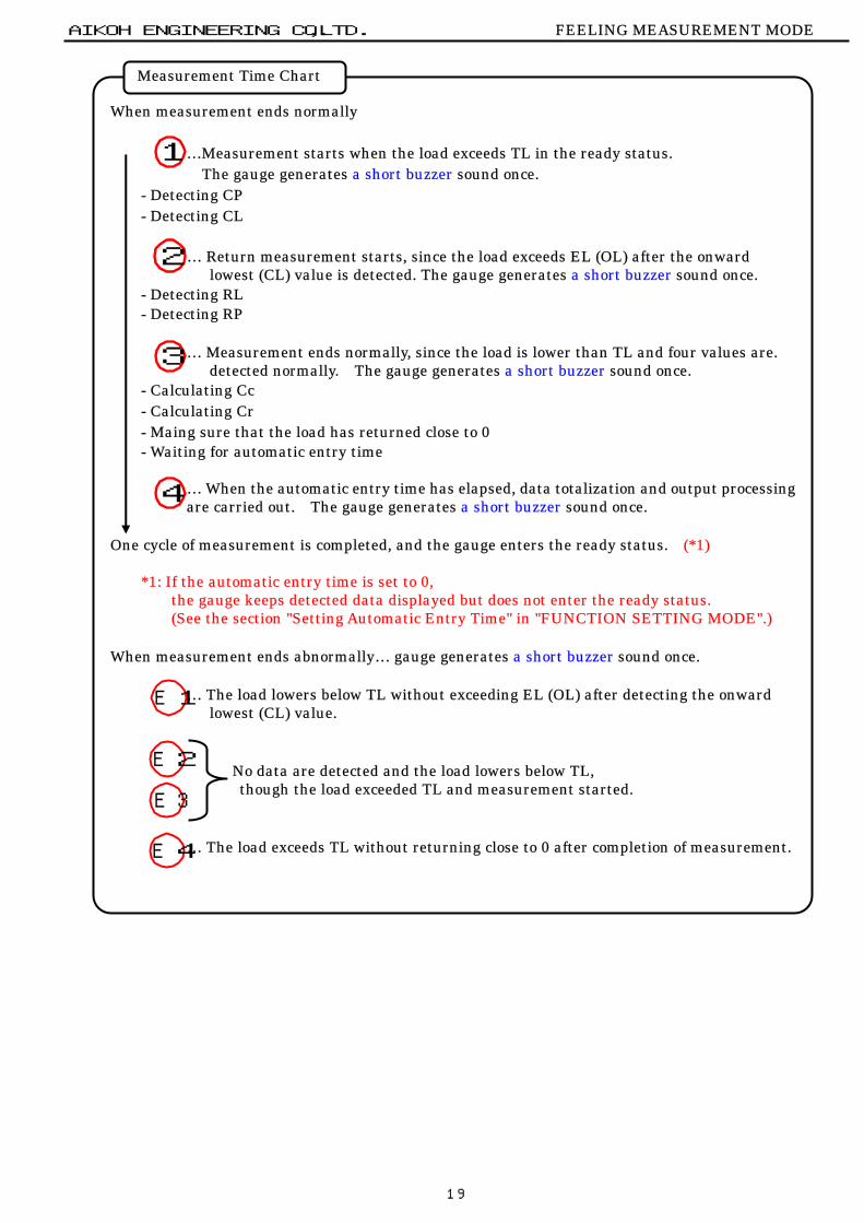
When measurement ends normally …Measurement starts when the load exceeds TL in the ready status. The gauge generates a short buzzer sound once.
- Detecting CP - Detecting CL
… Return measurement starts, since the load exceeds EL (OL) after the onward lowest (CL) value is detected. The gauge generates a short buzzer sound once.
- Detecting RL - Detecting RP
… Measurement ends normally, since the load is lower than TL and four values are. detected normally. The gauge generates a short buzzer sound once.
- Calculating Cc - Calculating Cr - Maing sure that the load has returned close to 0 - Waiting for automatic entry time
… When the automatic entry time has elapsed, data totalization and output processing are carried out. The gauge generates a short buzzer sound once.
One cycle of measurement is completed, and the gauge enters the ready status. (*1)
*1: If the automatic entry time is set to 0, the gauge keeps detected data displayed but does not enter the ready status. (See the section "Setting Automatic Entry Time" in "FUNCTION SETTING MODE".)
When measurement ends abnormally… gauge generates a short buzzer sound once.
… The load lowers below TL without exceeding EL (OL) after detecting the onward lowest (CL) value.
No data are detected and the load lowers below TL, though the load exceeded TL and measurement started.
… The load exceeds TL without returning close to 0 after completion of measurement.
Measurement Time Chart
1
2
3
4
E4
E3
E2
E1

20
CALIBRATION MODE
…The calibration mode is used to calibrate the gauge.
The Model-RX-FL gauge has been properly calibrated in the factory before shipment and needs no special calibration unless otherwise required Our company assumes that the customer has good understanding about this instruction manual and takes the responsibility of executing calibration. Our company will not accept further inquiries about calibration. Be sure to enter the calibration mode from the track mode.
- Two positive (+) points plus two negative (-) points (four points in all) or points 1 to 4
may be calibrated in this mode. … Press this key for three seconds or more in the ready status to enter
the calibration mode.
Switching Calibration Points
… Switches the calibration points.
… Moves to setting of the displayed calibration point.
… Sets the origin, i.e., the reference of the load data, when the this key is held for three seconds or more
… Terminates the calibration mode and returns to the ready status.
AIKOH ENGINEERING CO.,LTD. CALIBRATION MODE
CALIBRATION MODE
Never carry out operation without using the reference weight. If the load fluctuates during operation, accurate calibration is disabled. In order to prevent abnormal calibration, setting is only allowed in the range of ±10% or less of the weight.
Do not use a flawed or
deformed jig.
If a flawed or deformed jig is used, it may break or slip, resulting in injury. If a test piece drops onto your foot, it is very dangerous.
Do not apply a load over the maximum measurement capacity.
If an excessive load is applied, the sensor may break. If a greater load is applied, the case or internal parts of the gauge may break, resulting in an accident.
Fix the gauge on a test stand, etc. and carry out measurement in the stable conditions. Using the gauge in an unstable condition may result in a failure in proper measurement.。
Switching Calibration Points
…Upper + point
…Lower + point
…Lower - point
…Upper - point

21
Simple Calibration Example: RX-FL-1 (10 N)
1. Fix the gauge to the test stand, etc. 2. Make sure that the gauge is turned on and in the ready status. 3. Attach a jig.
Attach a jig (attachment) for applying the reference load to the gauge. Set the origin shown in step 4 below in this condition.
- Setting on the + (compression) side - Setting on the - (tensile) side
When a compression load is applied, When a tensile load is applied, the gauge displays a positive (+) value. the gauge displays a negative (-) value. Use the Aikoh round flat compression Hang a jig (basket, etc.) on table (Model-CP-U40/80), etc. a hook type attachment, etc.
NOTE: The gauge has threads to mount an attachment. Screw the attachment firmly to the very end.
Use a jig that weighs not more than ±10% of the maximum load capacity.
Hook type attachment
Jig (basket, etc.)
AIKOH ENGINEERING CO.,LTD. CALIBRATION MODE
Simple Calibration Example: RX-FL-1 (10 N)
!

22
4. Set the origin.
Make sure that the gauge is in the calibration mode.
Hold the key for three seconds or more.
(Org) is displayed for approximately one second and the gauge returns to the ready status.
Press the key to enter the calibration mode again, and carry out the following.
5. Setting each calibration point
5-1 Input the value of the reference weight to be used. (10.000 N)
- Setting on the + (compression) side
Press the key in the condition
where is displayed. Input a value.
- Setting on the - (tensile) side
Press the key in the condition
where is displayed. Input a value.
- Changing the value
… Changes the value of the blinking digit from 0 to 9 by one.
… Shifts the blinking digit by one from left to right.
NOTE: If you attempt to carry out calibration at the maximum load capacity (10 N in this example), the value has already been set and need be changed.
Carry out work in the condition where a stable track value is displayed.If you attempt to carry out setting in the condition where a load over ±10% of the maximum load capacity is applied, an error occurs. Setting is not completed and the gauge returns to the ready status.
AIKOH ENGINEERING CO.,LTD. CALIBRATION MODE
Use the reference weight that weighs more than half the maximum load capacity.

23
5-2 Apply the load to the gauge using the reference weight (10 N).
- Setting on the + (compression) side - Setting on the - (tensile) side
5-3 Press the key shortly. The applied load is set as an input value.
NOTE: The buzzer sounds shortly three times unless proper setting is carried out. Retry operation from step 5-1 in such a case.
6. Make preparation for measurement and check. Remove the reference weight and jig to release the gauge from the load.
Turn off power once, and turn it on again.
Press the key to reset.
Make sure that the displayed value is zeroed. Make sure that calibration is completely using the reference weight without fail.
If the weight drops when putting it on the jig, it causes an accident. Be very careful.
- This section merely shows a simple calibration example. - If the weight of the reference weight is different from the set value,
proper measurement is disabled. Set the correct value before executing calibration.
- It is recommended that the load calibration should be done by our company once a year in order to guarantee the accuracy of the gauge. (Our company may also issue a traceability certificate.)
!
AIKOH ENGINEERING CO.,LTD. CALIBRATION MODE
10N
10N
If calibration is finished halfway, accurate measurement is disabled. Be sure to complete it to the end.

24
About Calibration Points
- About Calibration Points -
AIKOH ENGINEERING CO.,LTD. CALIBRATION MODE
Be sure to use CAL2 or CAL-2 for calibration of one or two points.
One-point or two-point calibration using CAL1 or CAL-1 only is disabled. !- Four-Point Calibration -
: Load before calibration
: Load after calibration
- Two-Point Calibration -
: Load before calibration
: Load after calibration

25
DETAILS OF FUNCTIONS
Data Memory Function
Automatic Power Off Function
Automatic Zero Resetting Function
AIKOH ENGINEERING CO.,LTD. DETAILS OF FUNCTIONS
DETAILS OF FUNCTIONS
This function turns off power automatically if any key operation is not done or the displayed load does not change for five minutes or more. - Cautions -
- If the automatic power off function is activated in the condition where a PC is connected with the gauge, some trouble may occur in such a case that the PC acquires data automatically, for example. It is recommended that the automatic power off function should be deactivated in such a case.
Automatic Power Off Function
This function, if activated, resets the value to zero at an interval of approximately two seconds when some values are detected due to vibrations even though no load is applied.
- Cautions - - This function is available in the track mode only.
Automatic Zero Resetting Function
This function is used to save data in the memory unit built in the gauge. The gauge stores memorized data even after the power is turned off. This function is also used to output measured data to a printer, etc. in a batch.
Key operations: ……………. Saves the current data. (*1)
+ … Deletes all memory data stored currently.
- Cautions -
- Once data are saved in a certain mode, they cannot be saved in any other mode. Delete the memory before saving data in another mode.
- It is possible to save data in the same unit. Delete the memory if the unit is changed. - The quantity and details of data to be saved differ with the measurement modes.
In the feeling measurement mode … Quantity of data that may be saved: 150 Save data: 1 data, 6 items (CP, CL, RL, RP, Cc & Cr)
(See the section "FEELING MEASUREMENT MODE".) In the track mode ……………………. Quantity of data that may be saved: 500
Save data: Track display data
*1: The memory indicator (M) is lit and the quantity of save data is displayed in the main display area for approximately one second if no data were stored in the memory. Hereinafter, the quantity of save data is displayed in the sub display area. Data are also output to the printer simultaneously if it is connected with the external I/O connector. (See the section "Printer Output Function".)
Data Memory Function

26
External Zero Resetting Function
External Contact Holding Function
This function holds the track value when the contact signal is input to the external I/O connector.
Pin assignment: Pin 28: Contact signal input pin…(HOLD IN) Pin 30: Digital ground…………….(GND) (See the section "External I/O Connector Pin Assignment".)
- When the contact signal is input to the above shown pins through the optional cable (RX-OP-1),
etc. and its status changes, the track value at that time is held. The external contact hold indicator (H) is lit in the display area.
Contact status : Open close: Held Close open: Held. Close close: Not held. Open open: Not held.
- Press the key to reset the held value.
The external contact hold indicator (H) goes out when the held value is reset.
- Cautions - - This function is available in the track mode only.
The external contact hold indicator (H) changes if the contact signal varies in the feeling measurement mode.
External Contact Holding Function
This function resets the value to zero and nulls the display when the reset signal is input to the external I/O connector. Pin assignment : Pin 29: Reset signal input pin…(ZERO IN)
Pin 30: Digital ground…………..(GND) (See the section "External I/O Connector Pin Assignment".)
-The display is nulled when the above shown pins are short-circuited with the optional cable (RX-OP-1), etc. Short-circuiting these pins causes absolute zero resetting.
- Cautions - - "0" remains displayed if these pins are short-circuited continuously. - The display null function is available in the track mode only. - This function is not available if data are stored in the memory.
External Zero Resetting Function
AIKOH ENGINEERING CO.,LTD. DETAILS OF FUNCTIONS

27
Memory Data Display Function
Analog Output Function
This function outputs analog voltage corresponding to the load applied currently through the external I/O connector. Output voltage: Approx. ±2 V/F.S. (maximum measurement capacity)
Pin assignment : 1 … Analog output (±2 V/F.S.) 2 … Analog ground (A. GND) (See the section "External I/O Connector Pin Assignment".)
- To bring the output voltage close to 0 V
Connect a digital voltmeter, etc. with the above shown pins using the optional cable (RX-OP-1), etc. and adjust the output voltage close to 0 V in the procedures shown in section "Adjusting Analog Output to Zero Finely".
- Cautions - - This function is not linked with the measured values (CP, CL, etc.) in the feeling measurement
mode.
Analog Output Function
AIKOH ENGINEERING CO.,LTD. DETAILS OF FUNCTIONS
This function displays the latest data stored in the memory unit on the main display area.
+ … Moves to this function from the ready status Key operations: … Returns to the ready status.
… Deletes the displayed data from the memory and returns to the ready status. (*1)
… Changes the displayed items from CP in the order of CP, CL, RL, RP, Cc and Cr if the data are saved in the feeling measurement mode.
The names of the items displayed in the main display area are displayedin the sub display area at that time.
*1: Six-item data per measurement cycle are deleted in the feeling measurement mode.
- Cautions -
- Note that data deleted with the key may not be restored.
Memory Data Display Function
28
Comparator Judgment Function
AIKOH ENGINEERING CO.,LTD. DETAILS OF FUNCTIONS
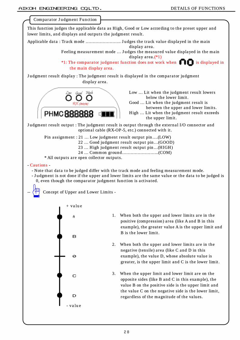
This function judges the applicable data as High, Good or Low according to the preset upper and lower limits, and displays and outputs the judgment result. Applicable data : Track mode ……………………. Judges the track value displayed in the main
display area. Feeling measurement mode … Judges the measured value displayed in the main
display area.(*1) *1: The comparator judgment function does not work when is displayed in
the main display area. Judgment result display : The judgment result is displayed in the comparator judgment
display area.
Low … Lit when the judgment result lowers below the lower limit.
Good … Lit when the judgment result is between the upper and lower limits.
High … Lit when the judgment result exceeds the upper limit.
Judgment result output : The judgment result is output through the external I/O connector and
optional cable (RX-OP-5, etc.) connected with it.
Pin assignment : 21 … Low judgment result output pin….(LOW) 22 … Good judgment result output pin…(GOOD) 23 … High judgment result output pin…(HIGH) 24 … Common ground……………………..(COM)
* All outputs are open collector outputs.
- Cautions - - Note that data to be judged differ with the track mode and feeling measurement mode. - Judgment is not done if the upper and lower limits are the same value or the data to be judged is
0, even though the comparator judgment function is activated. -- Concept of Upper and Lower Limits -
1. When both the upper and lower limits are in the
positive (compression) area (like A and B in this example), the greater value A is the upper limit and B is the lower limit.
2. When both the upper and lower limits are in the negative (tensile) area (like C and D in this example), the value D, whose absolute value is greater, is the upper limit and C is the lower limit.
3. When the upper limit and lower limit are on the opposite sides (like B and C in this example), the value B on the positive side is the upper limit and the value C on the negative side is the lower limit, regardless of the magnitude of the values.
Comparator Judgment Function
B
+ value
- value
A
C
D
0

29
Overload External Output Function
Printer Output Function
AIKOH ENGINEERING CO.,LTD. DETAILS OF FUNCTIONS
This function outputs signals to the external I/O connector and optional cable (RX-OP-5, etc.) connected with it, if a load over the maximum measurement capacity is input.
Pin assignment : 25 … OVER LOAD UP 26 … OVER LOAD DOWN 27 … Common ground (OVER LOAD COM) (See the section "External I/O Connector Pin Assignment".)
* All outputs are open collector outputs.
- Cautions - - Note that the output signals differ with the "overload output setting".
Overload External Output Function
Improper setting may cause breakdown.
Check the setting carefully. !
Setting Load input direction Pin No.Positive side (Compression) 25Negative side (Tensile) 26Positive side (Compression) 26Negative side (Tensile) 25
Relationship between overload output setting & pin No.
This function outputs data stored in the memory to a connected printer. Key operations : + … Outputs all stored data.
+ … Outputs the data displayed in the main display area among stored data. (*1 & *2)
…………….… Outputs the latest data.
*1: All data are output if track values are stored.
*2: No data are output if is set in the main display area.
- Cautions - - Data may sometimes be printed improperly, depending on the "RS-232C connection setting". Check the setting. - The output data, output format, etc. depend on the connected printer.
(See the section "External Instruments and Output Data".)
Printer Output Function
30
REFERENCES
About Data Communication
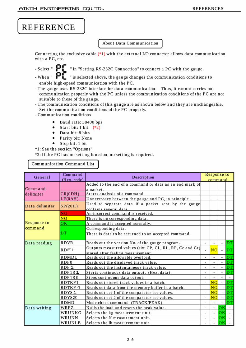
Connecting the exclusive cable (*1) with the external I/O connector allows data communication with a PC, etc.
- Select " " in "Setting RS-232C Connection" to connect a PC with the gauge.
- When " " is selected above, the gauge changes the communication conditions to enable high-speed communication with the PC.
- The gauge uses RS-232C interface for data communication. Thus, it cannot carries out communication properly with the PC unless the communication conditions of the PC are not suitable to those of the gauge.
- The communication conditions of this gauge are as shown below and they are unchangeable. Set the communication conditions of the PC properly.
- Communication conditions
● Baud rate: 38400 bps ● Start bit: 1 bit (*2) ● Data bit: 8 bits ● Parity bit: None ● Stop bit: 1 bit
*1: See the section "Options". *2: If the PC has no setting function, no setting is required. Communication Command List
AIKOH ENGINEERING CO.,LTD. REFERENCES
Communication Command List
About Data Communication
REFERENCE
General Command(Hex. code) Description
Added to the end of a command or data as an end mark ofa packet.
CR(0DH) Starts analysis of a command.LF(0AH) Unnecessary between the gauge and PC, in principle.
Data delimiter SP(20H) Used to separate data if a packet sent by the gaugecontains several data.
NG An incorrect command is received.NO There is no corresponding data.OK A command is accepted normally.
DTCorresponding data.There is data to be returned to an accepted command.
RDVR Reads out the version No. of the gauge program. - - - DTRDFL
Outputs measured values (six: CP, CL, RL, RP, Cc and Cr)stored after feeling measurement.
- NO - DTRDMDL Reads out the allowable overload. - - - DTRDF0 Reads out the displayed track value. - - - DTRDF1 Reads out the instantaneous track value. - - - DTRDF1R1 Starts continuous data output. (Hex. data) - - - DTRDF1RE Stops continuous data output. - - - - RDTKF1 Reads out stored track values in a batch. - NO - DTRDTKF4 Reads out data from the memory buffer in a batch. - NO - DTRDYS1 Reads out set 1 of the comparator set values. - NO - DTRDYS2 Reads out set 2 of the comparator set values. - NO - DTRDMD Mode check command (TRACK/PEAK) - - - DTWRFZ Nulls the load and resets the peak value. - - OK - WRUNKG Selects the kg measurement unit. - - OK - WRUNN Selects the N measurement unit. - - OK - WRUNLB Selects the lb measurement unit. - - OK -
Data writing
Response tocommand
Response tocommand
Commanddelimiter
Data reading

31
External Instruments and Output Data
AIKOH ENGINEERING CO.,LTD. REFERENCES
External Instruments and Output Data
Operation Instrument Setting Data type Outputdata
Feeling measurement data ATrack data NoFeeling measurement data ErrTrack data ErrFeeling measurement data BTrack data NoFeeling measurement data ErrTrack data ErrFeeling measurement data CTrack data NoFeeling measurement data ATrack data DFeeling measurement data ErrTrack data ErrFeeling measurement data BTrack data EFeeling measurement data ErrTrack data ErrFeeling measurement data NoTrack data NoFeeling measurement data FTrack data GFeeling measurement data ErrTrack data ErrFeeling measurement data HTrack data IFeeling measurement data ErrTrack data ErrFeeling measurement data NoTrack data NoFeeling measurement data JTrack data GFeeling measurement data ErrTrack data ErrFeeling measurement data KTrack data IFeeling measurement data ErrTrack data ErrFeeling measurement data NoTrack data NoFeeling measurement data NoTrack data NoFeeling measurement data NoTrack data NoFeeling measurement data HTrack data IFeeling measurement data NoTrack data NoFeeling measurement data NoTrack data No
(*2)When feelingmeasurement finishes(*1)
PC (RS-232C)
BL-58RSⅡ(SANEI)
(*2)
BL-58RSⅡ(SANEI)
PC (RS-232C)
BL-58RSⅡ(SANEI)
PC (RS-232C)
When key is pressed
When DATA key is pressed(*3)
When +
keys are pressed
BL-58RSⅡ(SANEI)
(*2)
PC (RS-232C)
(*2)
When +
keys are pressed(*2)
PC (RS-232C)
DP-1VR(MITSUTOYO)
DP-1VR(MITSUTOYO)
DP-1VR(MITSUTOYO)
DP-1VR(MITSUTOYO)
BL-58RSⅡ(SANEI)
DP-1VR(MITSUTOYO)
A
B
C
D
E
F
G
H
I
J
K
No
Err
*1:*2:*3:*4:
Not influenced by the Prn/Pc setting when the DP-1VR is connected.
Among the latest data stored in the memory, the memory No., item name,measured value, and comparator judgment result (*4) of the item set inthe main display area are only output.Among the latest data stored in the memory, the measured value of theitem set in the main display area is only output.
The latest data stored in the memory are output in the order of thememory No., track value and comparator judgment result. (*4)
All data stored in the memory are output in the order of the memory No.,item name, measured value (6 items), and comparator judgment result.(*3)All data stored in the memory are output in the order of the memory No.,track value and comparator judgment result. (*4)Among the latest data stored in the memory, measured values (6 items)are output.
No data is output.Output data are indefinite, since the communication conditions of theinstrument are not suitable to those of the gauge.
AOutput only when AutoEnter is set to a value other than 0.
The latest data stored in the memory are output in the order of thememory No., item name, measured value (6 items), and comparatorjudgment result. (*4)Among the latest data stored in the memory, the measured value of theitem set in the main display area is only output.。Measured value (6 items) stored after completion of measurement areoutput.
Among the latest data stored in the memory, the track value is output.
Output data
Among the latest data stored in the memory, track values are output.
This key is provided on the DP-1VR.Comparator judgment result is output only when the comparator functionis validated only.
32
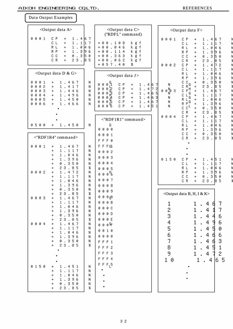
Data Output Examples
<Output data A> 0001 CP + 1.467 N G CL + 1.117 N RL + 1.046 N RP + 1.396 N CC + 0.350 N CR + 23.85 %
<Output data J> 0001 CP + 1.467 N G 0002 CP + 1.472 N H 0003 CP + 1.465 N G 0004 CP + 1.463 N G 0005 CP + 1.467 N G 0006 CP + 1.451 N L
AIKOH ENGINEERING CO.,LTD. REFERENCES
Data Output Examples
<Output data C> ("RDFL" command)
+00.108 kgf +00.046 kgf +00.114 kgf +00.363 kgf +00.062 kgf +057.40 %
<Output data F> 0001 CP + 1.467 N G CL + 1.117 N RL + 1.046 N RP + 1.396 N CC + 0.350 N CR + 23.85 % 0002 CP + 1.472 N H CL + 1.117 N RL + 1.046 N RP + 1.396 N CC + 0.350 N CR + 23.85 % 0003 CP + 1.467 N G CL + 1.117 N RL + 1.046 N RP + 1.396 N CC + 0.350 N CR + 23.85 % 0004 CP + 1.467 N G CL + 1.117 N RL + 1.046 N RP + 1.396 N CC + 0.350 N CR + 23.85 %
・
・
・ 0150 CP + 1.451 N L CL + 1.117 N RL + 1.046 N RP + 1.396 N CC + 0.350 N CR + 23.85 %
<Output data D & G> 0001 + 1.467 N G 0002 + 1.417 N L 0003 + 1.446 N G 0004 + 1.496 N H 0005 + 1.450 N G 0006 + 1.466 N G
・
・
・ 0500 + 1.450 N G
<"RDF1R4" command> 0001 + 1.467 N G + 1.117 N + 1.046 N + 1.396 N + 0.350 N + 23.85 % 0002 + 1.472 N H + 1.117 N + 1.046 N + 1.396 N + 0.350 N + 23.85 % 0003 + 1.467 N G + 1.117 N + 1.046 N + 1.396 N + 0.350 N + 23.85 % 0004 + 1.467 N G + 1.117 N + 1.046 N + 1.396 N + 0.350 N + 23.85 %
・
・
・ 0150 + 1.451 N L + 1.117 N + 1.046 N + 1.396 N + 0.350 N + 23.85 %
<"RDF1R1" command>
0000
0001
FFF0
FFF1
0002
0003
0004
0005
0006
0007
0008
0009
000A
000B
000C
000D
000E
000F
0010
0000
FFF1
FFF2
FFF3
FFF4
FFF5
・
・
・
・
<Output data B, H, I & K>
1 1.467 2 1.417 3 1.446 4 1.496 5 1.450 6 1.466 7 1.463 8 1.451 9 1.472
110 1.465
・
・
・
33
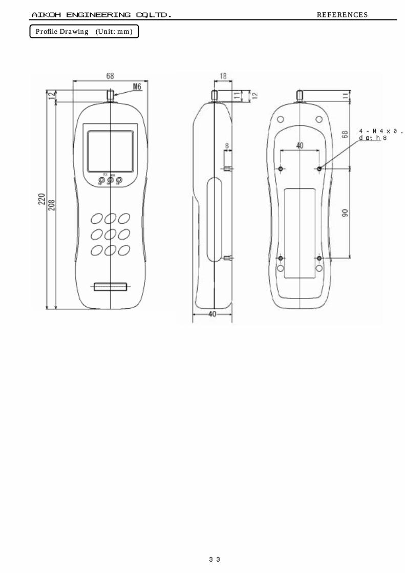
Profile Drawing
Profile Drawing (Unit: mm)
AIKOH ENGINEERING CO.,LTD. REFERENCES
4-M4x0.7depth8

34
External I/O Connector Pin Assignment
1 Analog output ±2 V/F.S.2 Analog ground3 RD4 RTS5 TD6 CTS7 D.GND8 GND9 Nc
10 Nc11 Nc12 Nc13 DP DATA14 DP CK15 DP RDY IN16 DP REQ IN17 Nc18 Nc19 Nc20 Nc21 COMPARATE LOW22 COMPARATE GOOD23 COMPARATE HIGH24 COMPARATE COM25 OVER LOAD UP26 OVER LOAD DOWN27 OVER LOAD COM28 HOLD IN29 ZERO IN30 GND
MITSUTOYO printer DP-1VR Use pin 8 for GND.
RS-232C
Analog output
Comparator judgment output
Overload output
External holdingExternal zero resetting
External I/O Connector Pin Assignment AIKOH ENGINEERING CO.,LTD. REFERENCES
3016
1 15
30-pin connector

35
Options
Optional cables
Options
AIKOH ENGINEERING CO.,LTD. REFERENCES
Optional cables
P i n N o .1
C o n n e c t o r 2
m o d e l N o . 3m a l e 4
C a s e 5m o d e l N o . 6
7N u m b e r 8o f p o l e s 9
1 01 11 21 31 41 51 61 71 81 92 02 12 22 32 42 52 62 72 82 93 0
3 0
D H A - P C 3 0 - 3 G ( D D K )
D H A - H P A 3 0 ( D D K )
C o n n e c t o r s h a p e
RX-OP-2 (RS-232C cable)
RX-OP-1 (Analog output cable)
S i g n a l W i r e c o l o r T e r m i n a t i o n± 2 V / F . S . o u t p u t R e d S o l d e r p l a t e dA n a l o g G N D B l a c k S o l d e r p l a t e dH O L D I N G r a y S o l d e r p l a t e dZ E R O I N B l u e S o l d e r p l a t e dG N D B r o w n S o l d e r p l a t e d
P i n N o .1
C o n n e c t o r 2
m o d e l N o . 3m a l e 4
C a s e 5m o d e l N o . 6
7N u m b e r 8o f p o l e s 9
1 01 11 21 31 41 51 61 71 81 92 02 12 22 32 42 52 62 72 82 93 0
3 0
D H A - P C 3 0 - 3 G ( D D K )
D H A - H P A 3 0 ( D D K )
C o n n e c t o r s h a p e P in N o . C o n n e c t o r s h a p e12 C o n n e c t o r t y p e D -s u b , 9 -P fe m a le3 c o n n e c t o r456 N u m b e r o f p o le s 9789

36
AIKOH ENGINEERING CO.,LTD. REFERENCES
RX-OP-3 (Printer cable DP-1VR)
P i n N o .12 C o n n e c t o r t y p e34 F o r f l a t c a b l e56 N u m b e r o f p o l e s 1 07891 0
S i g n a l W i r e c o l o r T e r m i n a t i o nH O L D I N G r a yZ E R O I N B l u eG N D B r o w n
C o n n e c t o r s h a p e
S h r i n k a b l e t u b e
( H I R O S EC O N N E C T O R )
H I F 3 B A - 1 0 D 2 . 5 4 R
RX-OP-5 (External control cable)
P in N o .123456 N u m b e r o f p o le s 3 67891 01 11 21 31 41 51 61 71 81 92 02 12 22 32 42 52 62 72 82 93 03 13 23 33 43 53 6
C o n n e c t o r & c a s e s e tm o d e l N o .
5 7 -6 0 3 6 0(D D K )
C o n n e c t o r s h a p e
C o n n e c t o r & c a s e s e tm o d e l N o .
5 7 -6 0 3 6 0(D D K )
A c c e s s o ry c o n n e c t o r
P i n N o .1
C o n n e c t o r 2
m o d e l N o . 3m a l e 4
C a s e 5m o d e l N o . 6
7N u m b e r 8o f p o l e s 9
1 01 11 21 31 41 51 61 71 81 92 02 12 22 32 42 52 62 72 82 93 0
3 0
D H A - P C 3 0 - 3 G ( D D K )
D H A - H P A 3 0 ( D D K )
C o n n e c t o r s h a p e
P i n N o .1
C o n n e c t o r 2
m o d e l N o . 3m a l e 4
C a s e 5m o d e l N o . 6
7N u m b e r 8o f p o l e s 9
1 01 11 21 31 41 51 61 71 81 92 02 12 22 32 42 52 62 72 82 93 0
3 0
D H A - P C 3 0 - 3 G ( D D K )
D H A - H P A 3 0 ( D D K )
C o n n e c t o r s h a p e
37
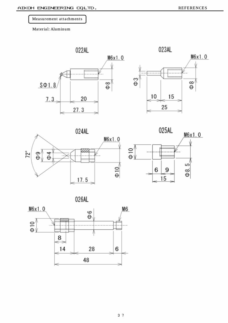
Measurement attachments Material: Aluminum
Measurement attachments
AIKOH ENGINEERING CO.,LTD. REFERENCES

38
Printers
Model : DP-1VR Type : Digimatic Mini processor Manufacturer : Mitsutoyo Co., Ltd. Outside dimensions : 94 W x 201 D x 75.2 H mm
Use the optional cable RX-OP-3 to connect this printer with the gauge. Contact Mitsutoyo Co., Ltd. for the operation method, setting, etc.
Model : BL-58RSII or BL2-58 Type : Thermal line dot printer Manufacturer : Sanei Electric Co., Ltd. Outside dimensions : 106 W x 76.6 H x 173 D mm Weight : Approx. 400 g (Printer only)
Use the optional cable RX-OP-2 to connect this printer with the gauge.
AIKOH ENGINEERING CO.,LTD. REFERENCES
Printers

39
Specifications
Specifications AIKOH ENGINEERING CO.,LTD. REFERENCES
Model RX-FL-1 RX-FL-2±10.00 N ±20.00 N±1000.0 (*1) ±2000 (*1)±2.205 lb (*1) ±4.409lb(*1)
Unit
Functions
Meas. accuracySampling freq.A/D converterProcessorDisplayDisplay refreshing freq.Allowable loadAuto power off time
Analog output
Ext. connectorOperating temp. rangeGuarantee temp. rangePower supplyContinuous run timeOutside dimensionsWeight
(*1):
(*2):(*3):(*4):
Max. meas. capacity
N, kg, lb (*1)Feeling measurementTrack load value, data memory, auto power offExt. hold input, ext. zero reset inputExt. analog output, ext. data outputExt. overload outputComparator judgment display & ext. output
The unit N (Newton) is only available on models for domestic use inJapan,
±0.2%/F.S.100 Hz (Sampling at 5 ms)16-bit, sampling at 100 kHz16-bit, single chip microprocessor7-segment LCD5 times/sec.
Either feeling measurement data or track values are stored.Digimatic Mini processor DP-1VR (made by Mitsutoyo Co., Ltd.)Line thermal printer BL-58RSII (made by Sanei Electric Co., Ltd.)100 VAC input - 6 VDC output (Model-761)
Data memory q'ty (*2)
220 VAC input - 6 VDC output (Model-762 for overseas countries)
150%/F.S.Approx. 5 minutesFeeling measurement data: 150/setTrack values: 500 valuesApprox. ±0.2 V/F.S.Exclusive printer I/O (*3)RS-232C I/O (*4)30-P half-pitch connector
Ext. data interface
0 to 40°C5 to 40°CExclusive battery (NiCd, 4.8 V), exclusive adapter (*5)Approx. 12 hours208 H x 68 W x 40 D mm (Projections not included)Approx. 450 g (Body only)
(*5):