model psb-2401 universal flat panel display wall mount...
TRANSCRIPT
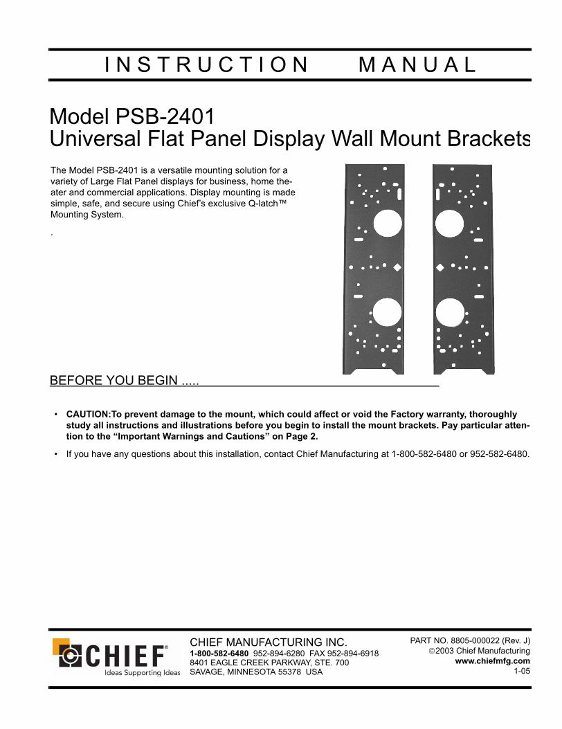
Model PSB-2401Universal Flat Panel Display Wall Mount Brackets
BEFORE YOU BEGIN .....
• CAUTION:To prevent damage to the mount, which could affect or void the Factory warranty, thoroughly study all instructions and illustrations before you begin to install the mount brackets. Pay particular atten-tion to the “Important Warnings and Cautions” on Page 2.
• If you have any questions about this installation, contact Chief Manufacturing at 1-800-582-6480 or 952-582-6480.
I N S T R U C T I O N M A N U A L
The Model PSB-2401 is a versatile mounting solution for a variety of Large Flat Panel displays for business, home the-ater and commercial applications. Display mounting is made simple, safe, and secure using Chief’s exclusive Q-latch™ Mounting System.
.
CHIEF MANUFACTURING INC.1-800-582-6480 952-894-6280 FAX 952-894-69188401 EAGLE CREEK PARKWAY, STE. 700SAVAGE, MINNESOTA 55378 USA
PART NO. 8805-000022 (Rev. J)2003 Chief Manufacturing
www.chiefmfg.com1-05

2
Instruction Manual PSB-2401
IMPORTANT WARNINGS and CAUTIONS!
WARNING: A WARNING alerts you to the possibility of serious injury or death if you do not follow the instructions.
CAUTION: A CAUTION alerts you to the possibility of damage or destruction of equipment if you do not follow the corre-sponding instructions.
• WARNING: Improper installation can result in serious personal injury! Make sure that the mounting surface struc-tural members can support a redundant weight factor five times the total weight of the equipment: if not, reinforce the mounting surface structural members before installing the mount.
• WARNING: You must use proper attaching hardware and installation procedures. Failure to use proper attaching hardware and installation procedures may result in equipment damage or serious personal injury.
• WARNING: Be aware of the potential for personal injury or damage to the unit if it is not adequately mounted.
• WARNING: The installer is responsible for verifying that the mounting surface structural members to which the mount is anchored will safely support the combined load of all attached components or other equip-ment.
• WARNING: The combined weight of the display panel must not exceed 150 lbs. (68.04 kg), the maximum load capac-ity of the mount.
• CAUTION: Check the unit for shipping damage before you begin the installation.
• CAUTION: Overtightening mounting screws may damage your Large Flat Panel display.
TOOLS REQUIRED FOR INSTALLATION
• Phillips screwdrivers, No. 1 and No. 2
• Allen wrench set
NOTE: Other tools may be required depending on the method of installation.

Instruction Manual PSB-2401
3
CONTENTS
PageINSPECT THE BRACKET BEFORE INSTALLING ..................................................................... 4
PARTS ............................................................................................................................................ 4
SELECT DISPLAY MODEL AND DETERMINE PARTS ........................................................... 5
DETERMINE MOUNTING BRACKET HOLE PATTERN .......................................................... 9
Groups 1-9 Hole Pattern ....................................................................................................... 9
Groups 10-14 Hole Pattern ................................................................................................... 10
Groups 15-17 Hole Pattern ................................................................................................... 11
DETERMINE BRACKET INSTALLATION PROCEDURES ....................................................... 13
Group 1 Installation Procedures ........................................................................................... 13
Group 2 Installation Procedures ........................................................................................... 15
Group 3 Installation Procedures ........................................................................................... 16
Group 4 Installation Procedures ........................................................................................... 17
Group 5 Installation Procedures ........................................................................................... 18
Group 6 Installation Procedures ........................................................................................... 19
Group 7 Installation Procedures ........................................................................................... 21
Group 8 Installation Procedures ........................................................................................... 22
Group 9 Installation Procedures ........................................................................................... 23
Group 10 Installation Procedures ......................................................................................... 24
Group 11 Installation Procedures ......................................................................................... 25
Group 12 Installation Procedures ......................................................................................... 26
Group 13 Installation Procedures ......................................................................................... 27
Group 14 Installation Procedures ......................................................................................... 28
Group 15 Installation Procedures ......................................................................................... 29
Group 16 Installation Procedures ......................................................................................... 30
Group 17 Installation Procedures ......................................................................................... 31

4
Instruction Manual PSB-2401
INSPECT THE BRACKET BEFORE INSTALLING
1. Carefully inspect the interface brackets (see Figure 1) for shipping damage.
2. If any damage is apparent, call your carrier claims agent and do not continue with the installation until the carrier has reviewed the damage.
PARTS
1. Read all assembly instructions before starting assembly.
2. Refer to Table 1 on page 4 and carefully inspect all parts bags to ensure all components are contained in each bag. If any components are missing, contact Chief Manufacturing at 1-800-582-6480 or 952-582-6480.
Table 1: Parts
Item Description Qty.
Bracket Left 1
Bracket Right 1
Parts Bag A
10-24 x 7/8” Button Head Cap Screw 4
10-24 Ny-Lock Nut 4
Mounting Button 4
1/8” Allen Key 1
Parts Bag B .75” OD x .26” ID x .375” Nylon Spacer 8
Parts Bag CM4 x 30mm Phillips Head Cap Screw 8
Steel Washer .55” OD x .25” ID x .0625” 8
Parts Bag D .75” OD x .344” ID x .50” Nylon Spacer 6
Parts Bag E M8 x 20mm Phillips Head Cap Screw 6
Parts Bag F M5 x 20mm Phillips Head Cap Screw 8
Parts Bag G M8 x 20mm Phillips Head Cap Screw 6
Parts Bag H M6 x 20mm Phillips Head Cap Screw 8
Parts Bag I M8 x 35mm Phillips Head Cap Screw 6
Parts Bag J M8 x 45mm Phillips Head Cap Screw 4
Parts Bag K 18mm OD x 8.3” ID x 20mm Nylon Spacer
6
Parts Bag L M5 x 25mm Phillips Head Cap Screw 6
Parts Bag M M8 x 65mm Phillips Head Cap Screw 4
Figure 1. Brackets

Instruction Manual PSB-2401
5
SELECT DISPLAY MODEL AND DETERMINE PARTS
The interface brackets are designed to fit a wide variety of brand names and model numbers.
To select the proper hardware and assembly procedures for your specific Large Flat Panel display model, do the following:
1. Using Table 2 on page 5, locate the model number of your Large Flat Panel display.
2. Record the group number and parts bags required for your Large Flat Panel display model.
NOTE: Not all hardware will be used for every installation. Do not discard extra hardware until installation is complete.
3. Using the information recorded in Step 2, proceed to “DETERMINE BRACKET INSTALLATION PROCE-DURES” on page 13.
Table 2: Flat Panel Display Model Numbers
Group No. Brand Name Model Number Parts Bag
1 Fujitsu 42” PDS-4208, PDS-4209, PDS-4211, PDS-4212, PDS-4213, PDS-4214, PDS-4221, PDS-4222, PDS-4229, PDS-4233, PDS-4234, PDS-4241, PDS4242
A, B, F
2 Fujitsu 42” P42 SERIES PLASMAS A, I, K
3 Fujitsu 50” P50 SERIES, P55XHA30WS A, B, E
4
Electrograph DTS4230
A, J, K
Fujitsu 50” PDS-5001, PDS-5002, PDS-5003, PDS-5004, P50XHA10US, P50XCA11UH, P50XCA10WH, P50XCA10EH, P50XCA10AH, P50XCA10UH, P50XCA11WH, P50XCA11EH, P50XCA11AH, P50XCA11UH, P50XCA12WH, P50XCA12EH, P50XCA12AH,
P50XCA12UH
JCV 50” GD-500PCE, GD-500PZU, GD-V501U, GD-V502U, GD-V502PCE
Panasonic 37” TH-37PW D4UZ, TH-37PW D5UZ, PT-37D4-P, PT-37P1, TH-37PW D4E, TH-37PW 5B, TH-37PW D5BX, TH-37PW D6UY, TH-37PX20UP
Panasonic 42” PH-42PWD3, PT-42PD1-P, PT-42PD2-P, PT-42P1, TH-42PW 3U, TH-42PW 4U, TH-42PW 4UY, PT-42PD3-P, TH-42PW 4EX, PT-42PHD4-P, TH-42PHD5UY,
TH-42PWD5UY, TH-42PWD6UY, TH-42PHD6UY, TH-42PWD5UY, TH-42PW5BX,TH-42PWD25UP, TH-42PXD20UP, TH-42PXD25UP, TH-42PW3E, TH-42PW3U,
TH-42PW5BX, TH-42PH5W
Panasonic 50” TH-50PHD3E, TH-50PHW5B, TH-50PHD5UY, TH-50PHD3U, TH-50PWD5EX,PT-50PHD3-P, PT-50PHD4-P, TH-50PHW5B, TH-50PHD5BX, TH-50PHD6UY,
TH-50PX20UP, TH-50PX26UP, TH-50PX26UP
RUNCO 42”& 50” PL-42CX, PL50CX
Toshiba 42” PD42W1, PD42WP16, PD42PW27
Toshiba 50” 50HP81, 50PW16, 50XP27
Viewsonic 42” VPW420
Yamaha 50” PDM-1
5 Panasonic TH-42PA20UPA10B, PT-TH37PA20U, TH42PA20UP, TH-42PA25UP A, M, K
6LG 40” MU-40PA10B
A, D, LZenith 40” SC352, P40V22, P40V24

6
Instruction Manual PSB-2401
7
AKIRA SV4202IQ
A, D, I
Electrograph DTS42W
Gateway 42”
HD Vision 46” HDV46P2
Net-TV 42” PDP-42V
Sampo PME-42S6, PME42X6
Viewsonic VPW425
8 BenQ 46” PDP46W1
A, B, H
Chungwa 46” SN4210P
Optoma 46” PD-46
PrincetonGraphics 46” AR4.6PDP
Gateway 46”
HD Vision HDV-46P2
Monivision PWV-46
Tatung 46” P46
V Inc. VIZIO P4, VIZIO P46
9 BenQ 42” PDP7859 A, B, H
Table 2: Flat Panel Display Model Numbers
Group No. Brand Name Model Number Parts Bag

Instruction Manual PSB-2401
7
10
Dreamvision 42” REVOLUTION ONE
A, B, C
Dreamvision 50” REVOLUTION FIVE
Faroujda FPP-42HD10, FPP-50HD10
Integra 50” PLA-50V1
Marantz 42” PD-4240, PD-4280, PD-4290D, PD-4292D, PD-4293D
Marantz 50” PD-5010, PD-5020, PD-5040
Mitsubishi 50” PD-5010, PD-5030
NEC 42” PX-42M2A, PX-42M3A, PX-42M4A, PX-42PD1, PX-42VP3A, PX-42M5A, PX42VM1A, PX-42VM2A, PX-42VP1A, PX-42VP2A, PX-42VP4, PX-42VP4D, PX42VM3A, PX-42VM4A,
PX-42XM2A, PX-42ZP4
NEC 50” PX-50M5A, PX-50VP1A, PX50XM1A, PX-50VP2A, PX-50XM2A, PX-50XMSA
Philips 50” 50FD9955, 50FD9934
RCA 42” PR42300
RCA 50” PHD50300
RUNCO 42” PL-42, PL-42c, CW-42, CW-42i
Sanyo 42” PDP-42WE1
Thomson 42” 42WS93E, 42WS94, 42WS95
Thomsan 50” 50WS94, 50WS95
Toshiba 42” 42HP82
Toshiba 50” 50HP82
Vidikron VP-42, VP-42HD, VP-50, VP-60, Crystal 50
Table 2: Flat Panel Display Model Numbers
Group No. Brand Name Model Number Parts Bag

8
Instruction Manual PSB-2401
11
Dukane 50” P50
A, B, E
EIZO 50” P5070, P5071
Hitachi 50” CMP5000WXE, CMP5000WXU, 50HDT50, 50HDT55, 50HDT60
Pioneer 43” PDP-4300, PDP-4310HD, PDP-4330HD, PDP-4340HD, PDP-433HDE, PDP-433PU, PDP-433CMX, PRO-800AB, PRO-800HD, PRO-900HD, PRO-910HD, PDP-433HDE,
PDP-434DHE
Pioneer 50” PDP-V501X, PDP-V501MC, PDP-V502MX, PDP-503HDE, PDP-505HD, PDP-503CMX, PRO 1000HD, PRO 1010HD, PDP-503HD, PDP-50MXE, PDP-5040HD, PRO-1110HD,
PRO-1120HD, PDP-5050HD
Polyvision 50” 9350
RCA 50” PHD505000
Runco 43” PL-43HDX, CW-43MC
Runco 50” CW-50MC, PL-50c, PL-50HDX
Sharp 43” PZ-43HV2U
Sharp 50” PZ-50HV2U, LC-PD50U
Trans-Lux PLASMA 5000
Viewsonic VPW500
12 JVC 42” GD-V4200PZW, GD-4210PZW, GD-4210PCE, GD-4211PZW, GM-P420UG, GM-P420PCE A, B, F
13
AKAI PDP-4290, PDP-4294
A, I, K
BY DESIGN 4222, 4232, 5032
HD Vision HDV42A
HELIOS HPTV4200A, HLTV4200B, HPTV4205A
HYUNDAI IMAGEQUEST PD421
Maxx 42” 4250, 4250T
Samsung 42” and 50”
PS-42P2S, PPM42S2, PPM42S3, SPL4225K, SPN4235, HPN4239, PPM50H3, PL42P3S, 50PZ60
14
Dwin HD-50
A, I, KSamsung 50” HPL5025, HPN5039, PDP-50VG, PDP-50HD, PPM50H2, PPM50H3
Maxx 50” 5000
Dwin 50” HD-50
15
Gateway 50”
A, D, IViewsonic VPW505
Sampo PME-50X6
Table 2: Flat Panel Display Model Numbers
Group No. Brand Name Model Number Parts Bag

Instruction Manual PSB-2401
9
16
AKIRA EPM 420
A, B, F
Cornea 42” MP4200
LG 42” MU-42PZ11B, MU42PZ13, MU42PZ17, MU-42PZ90V, RU42PZ90, RU-42PZ91, RU-42PZ92, RU-42PZ93, RU-42PZ40, RU-42PZ41, RU-42PZ44, RU-42PZ45, RU-42PZ46, RU-42PZ47
Planar 42” PDP-42B
Tatung 42” P42BLTL, TPD4201S
Zenith 42” P42W22, P42W24, P42W34
Mitsubishi 42” PD-4225
17
LG 50” MU50PZ41B, MZ-50PZ43, MZ-50PZ45V, MZ-50PZ46V, MZ-50PZ47V, MZ-50PZ90, MZ-50PZ91, MZ-50PZ92, MZ-50PZ93, MZ-50TV90V A, B, F
Zenith 50” P50W26, P50W28, P50W38
Table 2: Flat Panel Display Model Numbers
Group No. Brand Name Model Number Parts Bag

10
Instruction Manual PSB-2401
DETERMINE MOUNTING BRACKET HOLE PATTERN
Each interface bracket has 6 square holes for attaching mount-ing buttons (See Figure 2). These holes are arranged in a 14” vertical spacing pattern. When the proper hole pattern is used, the mounting buttons will form a 14” X 24” pattern when installed on your Large Flat Panel display.
The following steps will explain how to attach the mounting buttons in the proper square holes for your specific Large Flat Panel display model.
Groups 1-9 Hole PatternWARNING: Failure to use proper attaching hardware and
installation procedures may result in equip-ment damage or serious personal injury.
1. Lay the interface brackets out with the bent lip of each interface bracket down (see Figure 2).
2. Open parts bag A.
3. Using the mounting buttons and hardware in parts bag A, attach the mounting buttons in the square holes closest to the outside edge of each interface bracket (see Figure 2 and Figure 3).
4. Using the group number recorded your Large Flat Panel display model, proceed to “DETERMINE BRACKET INSTALLATION PROCEDURES” on page 13 and follow the instructions for your Large Flat Panel display model.
Item Description Qty.
Bracket Left 1
Bracket Right 1
Parts Bag A
10-24 x 7/8” Button Head Cap Screw 4
10-24 Ny-Lock Nut 4
Mounting Button 4
1/8” Allen Key 1
Figure 2. Brackets for Groups 1-9 with Bent Lip Down
Figure 3. Button Installation for Groups 1-9

Instruction Manual PSB-2401
11
Groups 10-14 Hole PatternWARNING:Failure to use proper attaching hardware and
installation procedures may result in equip-ment damage or serious personal injury.
1. Lay the interface brackets out with the bent lip of each interface bracket down (see Figure 4).
2. Open parts bag A.
3. Using the mounting buttons and the hardware in parts bag A, attach the mounting buttons in the center square holes of each interface bracket (see Figure 4 and Figure 5).
4. Using the group number recorded your Large Flat Panel display model, proceed to “DETERMINE BRACKET INSTALLATION PROCEDURES” on page 13 and follow the instructions for your Large Flat Panel display model.
Item Description Qty.
Bracket Left 1
Bracket Right 1
Parts Bag A
10-24 x 7/8” Button Head Cap Screw 4
10-24 Ny-Lock Nut 4
Mounting Button 4
1/8” Allen Key 1
Figure 4. Brackets for Groups 10-14 with Bent Lip Down
Figure 5. Button Installation for Groups 10-14
12
Instruction Manual PSB-2401
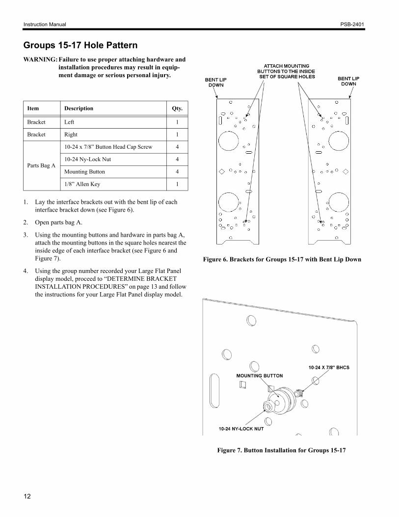
Groups 15-17 Hole PatternWARNING:Failure to use proper attaching hardware and
installation procedures may result in equip-ment damage or serious personal injury.
1. Lay the interface brackets out with the bent lip of each interface bracket down (see Figure 6).
2. Open parts bag A.
3. Using the mounting buttons and hardware in parts bag A, attach the mounting buttons in the square holes nearest the inside edge of each interface bracket (see Figure 6 and Figure 7).
4. Using the group number recorded your Large Flat Panel display model, proceed to “DETERMINE BRACKET INSTALLATION PROCEDURES” on page 13 and follow the instructions for your Large Flat Panel display model.
Item Description Qty.
Bracket Left 1
Bracket Right 1
Parts Bag A
10-24 x 7/8” Button Head Cap Screw 4
10-24 Ny-Lock Nut 4
Mounting Button 4
1/8” Allen Key 1
Figure 6. Brackets for Groups 15-17 with Bent Lip Down
Figure 7. Button Installation for Groups 15-17
Instruction Manual PSB-2401
13
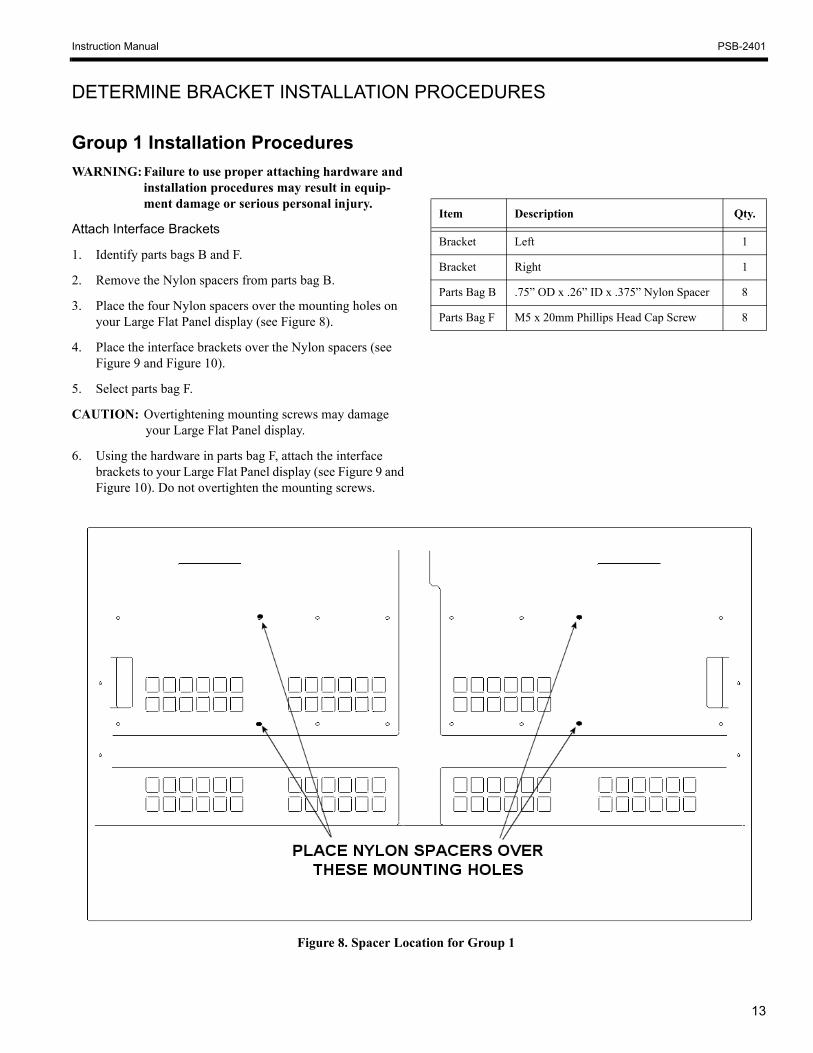
DETERMINE BRACKET INSTALLATION PROCEDURES
Group 1 Installation ProceduresWARNING: Failure to use proper attaching hardware and
installation procedures may result in equip-ment damage or serious personal injury.
Attach Interface Brackets
1. Identify parts bags B and F.
2. Remove the Nylon spacers from parts bag B.
3. Place the four Nylon spacers over the mounting holes on your Large Flat Panel display (see Figure 8).
4. Place the interface brackets over the Nylon spacers (see Figure 9 and Figure 10).
5. Select parts bag F.
CAUTION: Overtightening mounting screws may damage your Large Flat Panel display.
6. Using the hardware in parts bag F, attach the interface brackets to your Large Flat Panel display (see Figure 9 and Figure 10). Do not overtighten the mounting screws.
Item Description Qty.
Bracket Left 1
Bracket Right 1
Parts Bag B .75” OD x .26” ID x .375” Nylon Spacer 8
Parts Bag F M5 x 20mm Phillips Head Cap Screw 8
Figure 8. Spacer Location for Group 1

14
Instruction Manual PSB-2401
Figure 10. Bracket Attachment for Group 1
ATTACH MOUNTING BRACKETSUSING THESE HOLES
Figure 9. Spacer Installation for Group 1

Instruction Manual PSB-2401
15
Group 2 Installation ProceduresWARNING: Failure to use proper attaching hardware and
installation procedures may result in equip-ment damage or serious personal injury.
Attach Interface Brackets
1. Identify parts bags I and K.
2. Remove Nylon spacers from parts bag K.
3. Place the four Nylon spacers over the mounting holes on your Large Flat Panel display (see Figure 11).
4. Place the interface brackets over the Nylon spacers (see Figure 11 and Figure 12).
5. Select parts bag I.
CAUTION: Overtightening mounting screws may damage your Large Flat Panel display.
6. Using the hardware in parts bag I, attach the interface bracket to your Large Flat Panel display in the top slot and bottom hole in each interface bracket (see Figure 11 and Figure 12). Do not overtighten the mounting screws.
Item Description Qty.
Bracket Left 1
Bracket Right 1
Parts Bag I M8 x 35mm Phillips Head Cap Screw 6
Parts Bag K 18mm OD x 8.3” ID x 20mm Nylon Spacer
6
Figure 11. Spacer Installation for Group 2
Figure 12. Bracket Attachment for Group 2

16
Instruction Manual PSB-2401
Group 3 Installation ProceduresWARNING: Failure to use proper attaching hardware and
installation procedures may result in equip-ment damage or serious personal injury.
Attach Interface Brackets
1. Identify parts bags B and E.
2. Remove the Nylon spacers from parts bag B.
3. Place the four Nylon spacers over the mounting holes on your Large Flat Panel display.
4. Place the interface brackets over the Nylon spacers (see Figure 13 and Figure 14).
5. Select parts bag E.
CAUTION: Overtightening mounting screws may damage your Large Flat Panel display.
6. Using the hardware in parts bag E, attach the interface brackets to your Large Flat Panel display in the top slot and bottom hole in each interface bracket (See Figure 13 and Figure 14). Do not overtighten the mounting screws.
Item Description Qty.
Bracket Left 1
Bracket Right 1
Parts Bag B .75” OD x .26” ID x .375” Nylon Spacer 8
Parts Bag E M8 x 20mm Phillips Head Cap Screw 6
Figure 13. Spacer Installation for Group 3
Figure 14. Bracket Attachment for Group 3

Instruction Manual PSB-2401
17
Group 4 Installation ProceduresWARNING: Failure to use proper attaching hardware and
installation procedures may result in equip-ment damage or serious personal injury.
Attach Interface Brackets
1. Identify parts bags J and K.
2. Remove the Nylon spacers from parts bag K.
3. Place the four Nylon spacers over the mounting holes on your Large Flat Panel display (see Figure 15).
4. Place the interface brackets over the Nylon spacers (see Figure 15 and Figure 16).
5. Select parts bag J.
CAUTION: Overtightening mounting screws may damage your Large Flat Panel display.
6. Using the hardware in parts bag J, attach the interface brackets to your Large Flat Panel display in the top slot and bottom hole in each bracket (see Figure 15 and Figure 16). Do not overtighten the mounting screws.
Item Description Qty.
Bracket Left 1
Bracket Right 1
Parts Bag J M8 x 45mm Phillips Head Cap Screw 4
Parts Bag K 18mm OD x 8.3” ID x 20mm Nylon Spacer
6
Figure 16. Bracket Attachment for Group 4
Figure 15. Spacer Installation for Group 4

18
Instruction Manual PSB-2401
Group 5 Installation ProceduresWARNING: Failure to use proper attaching hardware and
installation procedures may result in equip-ment damage or serious personal injury.
Attach Interface Brackets
1. Identify parts bags M and K.
2. Remove the Nylon spacers from parts bag K.
3. Place the four Nylon spacers over the mounting holes on your Large Flat Panel display (see Figure 17).
4. Place the interface brackets over the Nylon spacers (see Figure 17 and Figure 18).
5. Select parts bag M.
CAUTION: Overtightening mounting screws may damage your Large Flat Panel display.
6. Using the hardware in parts bag M, attach the interface brackets to your Large Flat Panel display in the top slot and bottom hole in each bracket (see Figure 17 and Figure 18). Do not overtighten the mounting screws.
Item Description Qty.
Bracket Left 1
Bracket Right 1
Parts Bag K 18mm OD x 8.3” ID x 20mm Nylon Spacer
6
Parts Bag M M8 x 65mm Phillips Head Cap Screw 4
ATTACH MOUNTING BRACKETSUSING THESE HOLES
Figure 18. Bracket Attachment for Group 5
Figure 17. Spacer Installation for Group 5
Instruction Manual PSB-2401
19
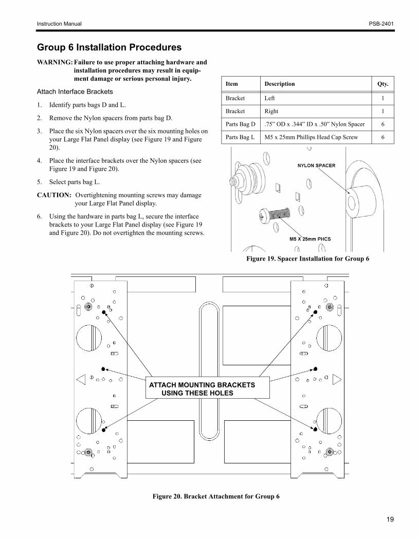
Group 6 Installation ProceduresWARNING: Failure to use proper attaching hardware and
installation procedures may result in equip-ment damage or serious personal injury.
Attach Interface Brackets
1. Identify parts bags D and L.
2. Remove the Nylon spacers from parts bag D.
3. Place the six Nylon spacers over the six mounting holes on your Large Flat Panel display (see Figure 19 and Figure 20).
4. Place the interface brackets over the Nylon spacers (see Figure 19 and Figure 20).
5. Select parts bag L.
CAUTION: Overtightening mounting screws may damage your Large Flat Panel display.
6. Using the hardware in parts bag L, secure the interface brackets to your Large Flat Panel display (see Figure 19 and Figure 20). Do not overtighten the mounting screws.
Item Description Qty.
Bracket Left 1
Bracket Right 1
Parts Bag D .75” OD x .344” ID x .50” Nylon Spacer 6
Parts Bag L M5 x 25mm Phillips Head Cap Screw 6
ATTACH MOUNTING BRACKETSUSING THESE HOLES
Figure 20. Bracket Attachment for Group 6
Figure 19. Spacer Installation for Group 6

20
Instruction Manual PSB-2401
THIS PAGEINTENTIONALLY
BLANK

Instruction Manual PSB-2401
21
Group 7 Installation ProceduresWARNING: Failure to use proper attaching hardware and
installation procedures may result in equip-ment damage or serious personal injury.
Attach Interface Brackets
1. Identify parts bags D and I.
2. Remove the Nylon spacers from parts bag D.
3. Place the Nylon spacers over the four mounting holes on your Large Flat Panel display (see Figure 21 and Figure 22).
4. Place the interface brackets over the Nylon spacers (see Figure 21).
5. Select parts bag I.
CAUTION: Overtightening mounting screws may damage your Large Flat Panel display.
6. Using the hardware in parts bag I, attach the interface brackets to your Large Flat Panel display (see Figure 21 and Figure 22). Do not overtighten the mounting screws.
Item Description Qty.
Bracket Left 1
Bracket Right 1
Parts Bag D .75” OD x .344” ID x .50” Nylon Spacer 6
Parts Bag I M8 x 35mm Phillips Head Cap Screw 6
Figure 22. Bracket Attachment for Group 7
Figure 21. Spacer Installation for Group 7

22
Instruction Manual PSB-2401
Group 8 Installation ProceduresWARNING: Failure to use proper attaching hardware and
installation procedures may result in equip-ment damage or serious personal injury.
Attach Interface Brackets
1. Identify parts bags B and H.
2. Remove the Nylon spacers from parts bag B.
3. Place the Nylon spacers over the six mounting holes on your Large Flat Panel display (see Figure 23 and Figure 24).
4. Place the interface brackets over the Nylon spacers (see Figure 24).
5. Select parts bag H.
CAUTION: Overtightening mounting screws may damage your Large Flat Panel display.
6. Using the hardware in parts bag H, attach the interface brackets to your Large Flat Panel display. Do not over-tighten the mounting screws.
Item Description Qty.
Bracket Left 1
Bracket Right 1
Parts Bag B .75” OD x .26” ID x .375” Nylon Spacer 8
Parts Bag H M6 x 20mm Phillips Head Cap Screw 8
Figure 23. Spacer Installation for Group 8
ATTACH MOUNTING BRACKETSUSING THESE HOLES
Figure 24. Bracket Attachment for Group 8

Instruction Manual PSB-2401
23
Group 9 Installation ProceduresWARNING: Failure to use proper attaching hardware and
installation procedures may result in equip-ment damage or serious personal injury.
Attach Interface Brackets
1. Identify parts bags B and H.
2. Remove the Nylon spacers from parts bag B.
3. Place the six Nylon spacers over the six mounting holes on your Large Flat Panel display (see Figure 25).
4. Place the interface brackets over the Nylon spacers (see Figure 25 and Figure 26).
5. Select parts bag H.
CAUTION: Overtightening mounting screws may damage your Large Flat Panel display.
6. Using the hardware in parts bag H, attach the interface brackets to your Large Flat Panel display in the two top slots and bottom hole of each interface bracket (see Figure 25 and Figure 26). Do not overtighten the mounting screws.
Item Description Qty.
Bracket Left 1
Bracket Right 1
Parts Bag B .75” OD x .26” ID x .375” Nylon Spacer 8
Parts Bag H M6 x 20mm Phillips Head Cap Screw 8
ATTACH MOUNTING BRACKETSUSING THESE HOLES
Figure 26. Bracket Attachment for Group 9
Figure 25. Spacer Location for Group 9

24
Instruction Manual PSB-2401
Group 10 Installation ProceduresWARNING: Failure to use proper attaching hardware and
installation procedures may result in equip-ment damage or serious personal injury.
Attach Interface Brackets
1. Identify parts bags B and C.
2. Remove the Nylon spacers from parts bag B.
3. Place the eight Nylon spacers over the mounting holes on your Large Flat Panel display (see Figure 27).
4. Place the interface brackets over the Nylon spacers (see Figure 27 and Figure 28).
5. Select parts bag C.
CAUTION: Overtightening mounting screws may damage your Large Flat Panel display.
6. Using the hardware in parts bag C, attach the interface brackets to your Large Flat Panel display using the top hole, middle two slots, and the bottom hole of each inter-face bracket (see Figure 27 and Figure 28). Do not over-tighten the mounting screws.
Item Description Qty.
Bracket Left 1
Bracket Right 1
Parts Bag B .75” OD x .26” ID x .375” Nylon Spacer 8
Parts Bag CM4 x 30mm Phillips Head Cap Screw 8
Steel Washer .55” OD x .25” ID x .0625” 8
ATTACH MOUNTING BRACKETSUSING THESE HOLES
Figure 28. Bracket Attachment for Group 10
Figure 27. Spacer Location for Group 10

Instruction Manual PSB-2401
25
Group 11 Installation ProceduresWARNING: Failure to use proper attaching hardware and
installation procedures may result in equip-ment damage or serious personal injury.
Attach Interface Brackets
1. Identify parts bags B and E.
2. Remove the Nylon spacers from parts bag B.
3. Place the six Nylon spacers over the mounting holes on your Large Flat Panel display (see Figure 29).
4. Place the interface brackets over the Nylon spacers (see Figure 29 and Figure 30).
5. Select parts bag E.
CAUTION: Overtightening mounting screws may damage your Large Flat Panel display.
6. Using the hardware in parts bag E, secure the interface brackets to your Large Flat Panel display using the six holes of each interface bracket (see Figure 29 and Figure 30). Do not overtighten the mounting screws.
Item Description Qty.
Bracket Left 1
Bracket Right 1
Parts Bag B .75” OD x .26” ID x .375” Nylon Spacer 8
Parts Bag E M8 x 20mm Phillips Head Cap Screw 6
ATTACH MOUNTING BRACKETSUSING THESE HOLES
Figure 30. Bracket Attachment for Group 11
Figure 29. Spacer Installation for Group 11

26
Instruction Manual PSB-2401
Group 12 Installation ProceduresWARNING: Failure to use proper attaching hardware and
installation procedures may result in equip-ment damage or serious personal injury.
Attach Interface Brackets
1. Identify parts bags B and F.
2. Remove the Nylon spacers from parts bag B.
3. Place the Nylon spacers over the eight mounting holes on your Large Flat Panel display (see Figure 31 and Figure 32).
4. Place the interface brackets over the Nylon spacers (see Figure 32).
5. Select parts bag F.
CAUTION: Overtightening mounting screws may damage your Large Flat Panel display.
6. Using the hardware in parts bags F, secure the interface brackets to your Large Flat Panel display (see Figure 32). Do not overtighten the mounting screws.
Item Description Qty.
Bracket Left 1
Bracket Right 1
Parts Bag B .75” OD x .26” ID x .375” Nylon Spacer 8
Parts Bag F M5 x 20mm Phillips Head Cap Screw 8
ATTACH MOUNTING BRACKETSUSING THESE HOLES
Figure 32. Bracket Attachment for Group 12
Figure 31. Spacer Installation for Group 12
Instruction Manual PSB-2401
27
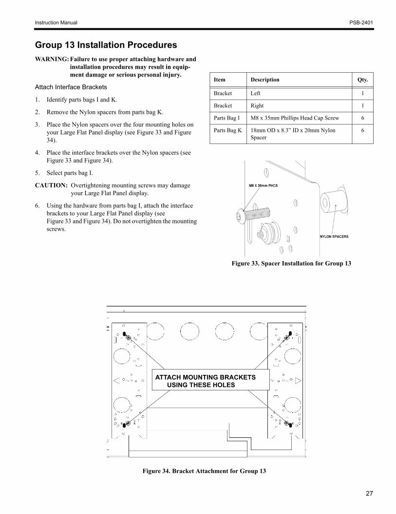
Group 13 Installation ProceduresWARNING: Failure to use proper attaching hardware and
installation procedures may result in equip-ment damage or serious personal injury.
Attach Interface Brackets
1. Identify parts bags I and K.
2. Remove the Nylon spacers from parts bag K.
3. Place the Nylon spacers over the four mounting holes on your Large Flat Panel display (see Figure 33 and Figure 34).
4. Place the interface brackets over the Nylon spacers (see Figure 33 and Figure 34).
5. Select parts bag I.
CAUTION: Overtightening mounting screws may damage your Large Flat Panel display.
6. Using the hardware from parts bag I, attach the interface brackets to your Large Flat Panel display (see Figure 33 and Figure 34). Do not overtighten the mounting screws.
Item Description Qty.
Bracket Left 1
Bracket Right 1
Parts Bag I M8 x 35mm Phillips Head Cap Screw 6
Parts Bag K 18mm OD x 8.3” ID x 20mm Nylon Spacer
6
ATTACH MOUNTING BRACKETSUSING THESE HOLES
Figure 34. Bracket Attachment for Group 13
Figure 33. Spacer Installation for Group 13
28
Instruction Manual PSB-2401
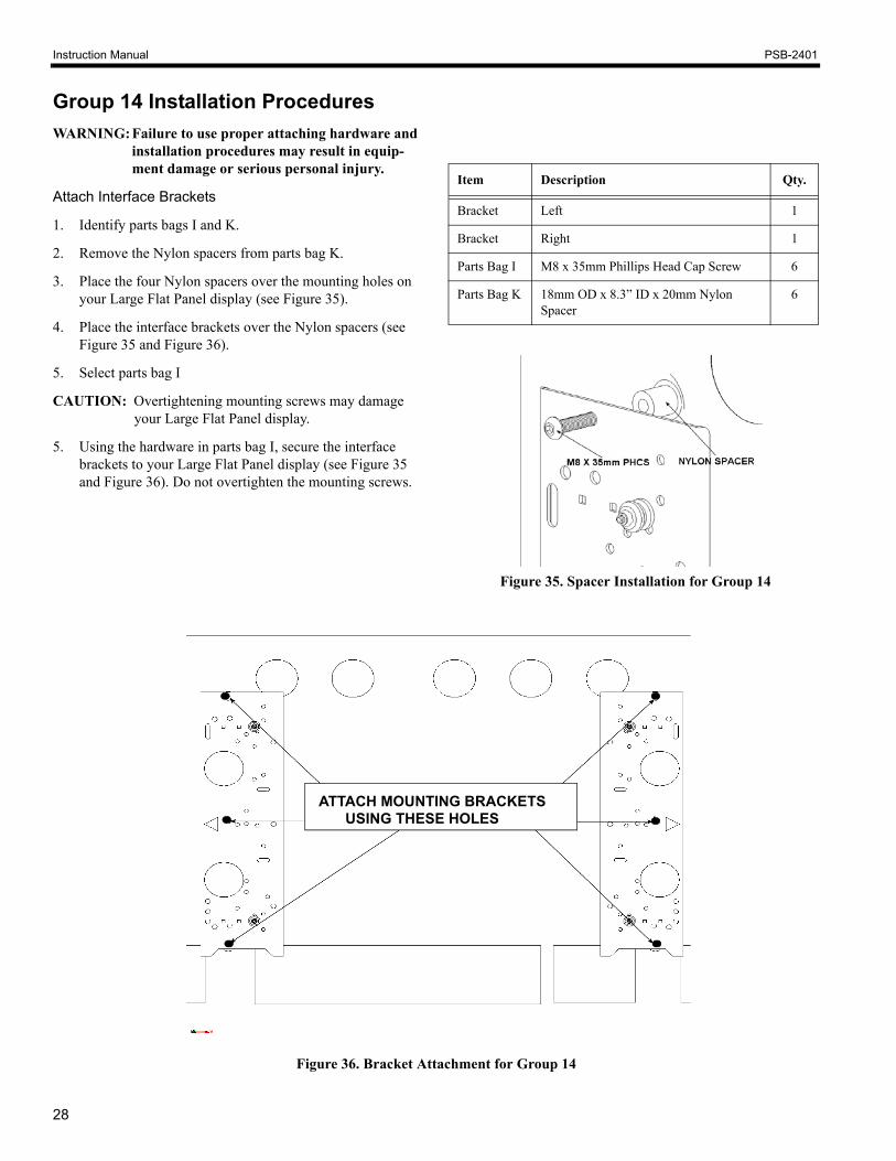
Group 14 Installation ProceduresWARNING: Failure to use proper attaching hardware and
installation procedures may result in equip-ment damage or serious personal injury.
Attach Interface Brackets
1. Identify parts bags I and K.
2. Remove the Nylon spacers from parts bag K.
3. Place the four Nylon spacers over the mounting holes on your Large Flat Panel display (see Figure 35).
4. Place the interface brackets over the Nylon spacers (see Figure 35 and Figure 36).
5. Select parts bag I
CAUTION: Overtightening mounting screws may damage your Large Flat Panel display.
5. Using the hardware in parts bag I, secure the interface brackets to your Large Flat Panel display (see Figure 35 and Figure 36). Do not overtighten the mounting screws.
Item Description Qty.
Bracket Left 1
Bracket Right 1
Parts Bag I M8 x 35mm Phillips Head Cap Screw 6
Parts Bag K 18mm OD x 8.3” ID x 20mm Nylon Spacer
6
ATTACH MOUNTING BRACKETSUSING THESE HOLES
Figure 35. Spacer Installation for Group 14
Figure 36. Bracket Attachment for Group 14

Instruction Manual PSB-2401
29
Group 15 Installation ProceduresWARNING: Failure to use proper attaching hardware and
installation procedures may result in equip-ment damage or serious personal injury.
Attach Interface Brackets
1. Identify parts bags D and I.
2. Remove the Nylon spacers from parts bag D.
3. Place the Nylon spacers over the six mounting holes on your Large Flat Panel display (see Figure 37).
4. Place the interface brackets over the Nylon spacers (see Figure 37 and Figure 38).
5. Select parts bag I.
CAUTION: Overtightening mounting screws may damage your Large Flat Panel display.
5. Using the hardware from parts bag I, attach the interface brackets to your Large Flat Panel display (see Figure 37 and Figure 38). Do not overtighten the mounting screws.
Item Description Qty.
Bracket Left 1
Bracket Right 1
Parts Bag D .75” OD x .344” ID x .50” Nylon Spacer 6
Parts Bag I M8 x 35mm Phillips Head Cap Screw 6
Figure 37. Spacer Installation for Group 15
Figure 38. Bracket Attachment for Group 15

30
Instruction Manual PSB-2401
Group 16 Installation ProceduresWARNING: Failure to use proper attaching hardware and
installation procedures may result in equip-ment damage or serious personal injury.
Attach Interface Brackets
1. Identify parts bags B and F.
2. Remove the Nylon spacers from parts bag B.
3. Place the Nylon spacers over the six mounting holes on your Large Flat Panel display (see Figure 39).
4. Place the interface brackets over the Nylon spacers (see Figure 39 and Figure 40).
5. Select parts bag F.
CAUTION: Overtightening mounting screws may damage your Large Flat Panel display.
5. Using the hardware from parts bag F, attach the interface brackets to your Large Flat Panel display (see Figure 39 and Figure 40). Do not overtighten the mounting screws.
Item Description Qty.
Bracket Left 1
Bracket Right 1
Parts Bag B .75” OD x .26” ID x .375” Nylon Spacer 8
Parts Bag F M5 x 20mm Phillips Head Cap Screw 8
Figure 39. Spacer Installation for Group 16
ATTACH MOUNTING BRACKETSUSING THESE HOLES
Figure 40. Bracket Attachment for Group 16

Instruction Manual PSB-2401
31
Group 17 Installation ProceduresWARNING: Failure to use proper attaching hardware and
installation procedures may result in equip-ment damage or serious personal injury.
Attach Interface Brackets
1. Identify parts bags B and F.
2. Remove the Nylon spacers from parts bag B.
3. Place the Nylon spacers over the six mounting holes on your Large Flat Panel display (see Figure 41).
4. Place the interface brackets over the Nylon spacers (see Figure 41 and Figure 42).
5. Select parts bag F.
CAUTION: Overtightening mounting screws may damage your Large Flat Panel display.
6. Using the hardware from parts bag F, attach the interface brackets to your Large Flat Panel display (see Figure 41 and Figure 42). Do not overtighten the mounting screws.
Item Description Qty.
Bracket Left 1
Bracket Right 1
Parts Bag B .75” OD x .26” ID x .375” Nylon Spacer 8
Parts Bag F M5 x 20mm Phillips Head Cap Screw 8
Figure 41. Spacer Installation for Group 17
ATTACH MOUNTING BRACKETSUSING THESE HOLES
Figure 42. Bracket Attachment for Group 17
