model ps002 - scene7
TRANSCRIPT

MODEL PS002Power Supply Module
for Zero Two A Applications
The information and technical data disclosed in thisdocument may be used and disseminated only for thepurposes and to the extent specifically authorized inwriting by General Monitors.
Instruction Manual 12-01
General Monitors reserves the right to changepublished specifications and designs without priornotice.
MANPS002
Part No. MANPS002Revision B/12-01

Model PS002
i
Warranty StatementGeneral Monitors warrants the Model PS002 to be free from defects inworkmanship or material under normal use and service within two (2) years fromthe date of shipment. General Monitors will repair or replace without charge anyequipment found to be defective during the warranty period. Full determination ofthe nature of, and responsibility for, defective or damaged equipment will bemade by General Monitors’ personnel. Defective or damaged equipment must beshipped prepaid to the General Monitors’ plant or the representative from whichshipment was made. In all cases, this warranty is limited to the cost of theequipment supplied by General Monitors. The customer will assume all liabilityfor the misuse of this equipment by its employees or other personnel. Allwarranties are contingent upon proper use in the application for which theproduct was intended and do not cover products which have been modified orrepaired without General Monitors’ approval or which have been subjected toneglect, accident, improper installation or application, or on which the originalidentification marks have been removed or altered.
Except for the express warranty stated above, General Monitors disclaims allwarranties with regard to the products sold, including all implied warranties ofmerchantability and fitness and the express warranties stated herein are in lieu ofall obligations or liabilities on the part of General Monitors for damages including,but not limited to, consequential damages arising out of/or in connection with theuse or performance of the product.
WarningAll Zero Two A Series Modules contain components, which can be damaged bystatic electricity. Special care must be taken when wiring the system to ensurethat only the connection points are touched.
Installation and Maintenance must be carried out by suitably skilled andcompetent personnel only.

Model PS002
ii
Table of ContentsWarranty Statement ......................................................................................iWarning ......................................................................................iTable of Contents .....................................................................................iiTable of Figures ....................................................................................iii
1.0 Introduction .................................................................................... 11.1 System Description................................................................... 11.2 Power Supply Module - PS002 ................................................. 3
2.0 Installation .................................................................................... 42.1 Upon receipt of your equipment ................................................ 42.2 Chassis Installation................................................................... 42.3 Terminal Connections............................................................... 4
3.0 Operation .................................................................................... 73.1 Power Supply Operation........................................................... 7
4.0 Appendix .................................................................................... 84.1 Specifications........................................................................... 8
4.1.1 System Specifications.................................................. 84.1.2 Mechanical Specifications............................................ 84.1.3 Electrical Specifications ............................................... 84.1.4 Environmental Specifications ....................................... 8
4.2 Engineering Documentation...................................................... 94.2.1 Outline & Dimensional Drawing - PS002 .......................... 9

Model PS002
iii
Table of Figures
Figure 1 Types of Zero Two A Series Gas and Flame Detection Modules ..... 1Figure 2 Zero Two A Series Accessory Modules........................................... 1Figure 3 Zero Two A Series Gas and Flame Detection Modules.................... 1Figure 4 Zero Two A Accessory Module........................................................ 3Figure 5 Wire Strip Length ............................................................................ 4Figure 6 Rear Connector Terminations ......................................................... 5Figure 7 Auxiliary +24VDC Output ................................................................ 5Figure 8 Terminations for DC Voltage Input .................................................. 5Figure 9 Terminations for AC Input Power .................................................... 6Figure 10 PS002 Voltage Selection ................................................................ 7Figure 11 Outline & Dimensional Drawing - PS002......................................... 9
Model PS002
1
1.0 Introduction1.1 System Description
The Zero Two A Series of Trip Amplifiers and Control Modules have beendeveloped for the purpose of creating combined fire and gas detection systems(see Figure 1). There is a module for flame detection and each type of gasdetection that General Monitors offers.
Module Type of field device4802A Combustible Gas Sensors2602A Hydrogen Sulfide (H2S) Gas Sensors
TA102A Combustible Gas Smart SensorsTA202A Hydrogen Sulfide (H2S) Gas Smart SensorsTA402A FL3100 Family of Flame DetectorsTA502A Generic Trip Amplifier
Figure 1 – Types of Zero Two A Series Gas and Flame Detection Modules
In addition to the Fire and Gas Detection Modules, there are Accessory Modulesthat perform system functions (e.g. alarm reset, alarm accept), and will enhancethe performance of the system (e.g. extra relay capacity, zoning and voting).(See Figure 2)
Module DescriptionPS002 Power Supply Module
FM002A Facilities ModuleMD002 Monitored Driver ModuleIN042 4-Channel Input CardCC02A Communications ModuleZN002A Zone Control Module
Figure 2 – Zero Two A Series Accessory Modules
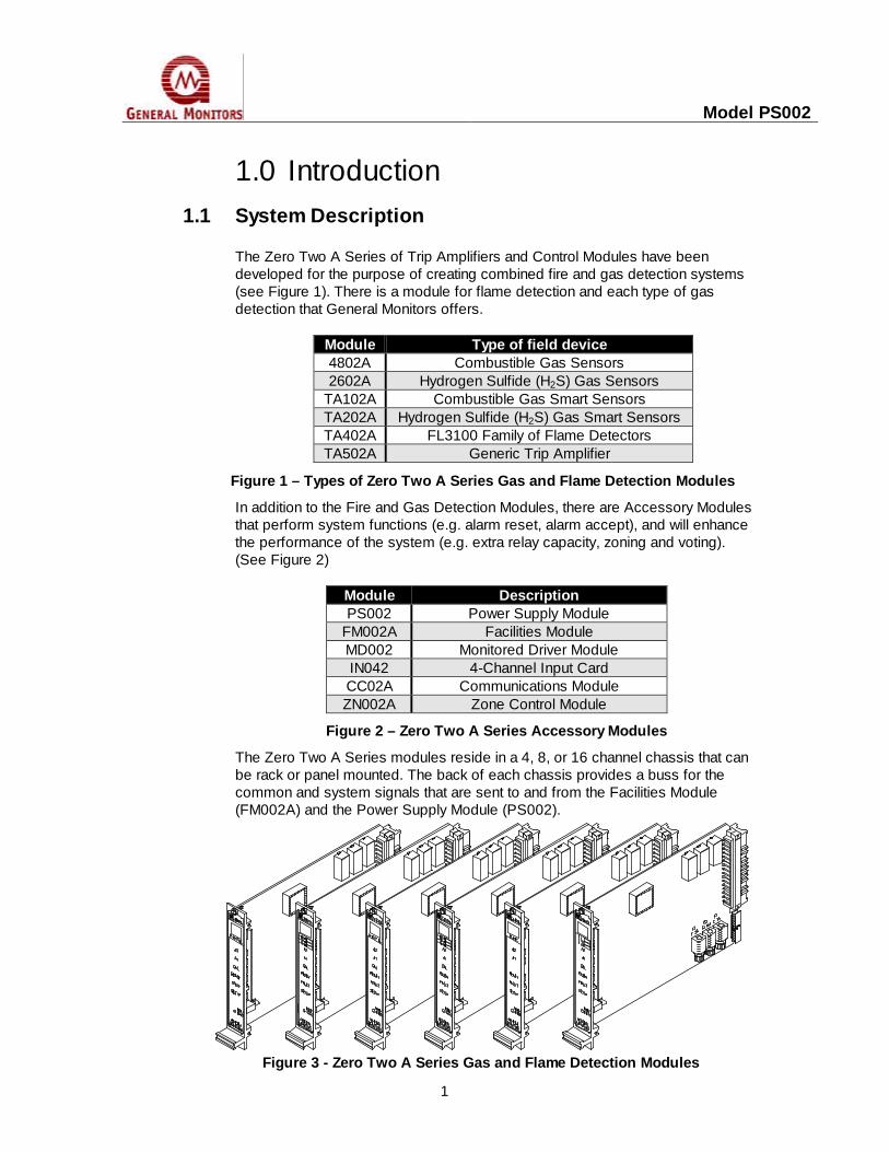
The Zero Two A Series modules reside in a 4, 8, or 16 channel chassis that canbe rack or panel mounted. The back of each chassis provides a buss for thecommon and system signals that are sent to and from the Facilities Module(FM002A) and the Power Supply Module (PS002).
Figure 3 - Zero Two A Series Gas and Flame Detection Modules

Model PS002
2
The bussed signals are labeled as follows:
+24 VDC Positive Supply VoltageCommon System Ground
The power connections are labeled "+24 VDC" and "Common". Each moduleoperates from a +24VDC (nominal) input. This regulated +24VDC source is fedto an on board power supply circuit. This power supply produces the necessarysupply voltages and currents for operating all of the circuitry on the module andthe detection device in the field. The Power Supply Module (PS002), or acustomer supplied power supply, provides the buss with the "+24VDC" for themodules.
A1 Alarm Level 1A2 Alarm Level 2
There are two separate alarm levels labeled "A1" and "A2". The "A2" alarm levelis the most severe condition. These signals are sent to the Facilities Module.
Fault Malfunction
The "Fault" line signals the Facilities Module any time any of the modules in thesystem enters into a malfunction condition.
Accept Alarm Accept
Alarm levels are accepted and the UA is de-activated when the "ACCEPT" buttonon the front panel of the Facilities Module is depressed. This signal is sent to allof the modules on the buss by the Facilities Module.
UA Unaccept / Acknowledge
The "UA" is activated anytime a new alarm level is activated. When an activatedalarm level is accepted, the "UA" is de-activated. The "UA" will re-activate ifanother alarm level is activated.
Reset Master Reset
Another button is provided on the front panel of the Facilities Module so thatlatched alarm levels can be "RESET". This signal is sent to all of the modules onthe buss by the Facilities Module.

Model PS002
3
CAL CALIBRATE
Any time the a module in the system is placed into calibration Mode, a signal issent on the buss to the Facilities Module.
Figure 4 - Zero Two A Accessory Module
1.2 Power Supply Module - PS002
The Power supply Module (PS002) provides a system with sufficient power tooperate twelve (12) channels of Zero Two A Series Modules and their fielddevices. This module is four (4) times as wide as other modules and requiresfour times the space.
The Power Supply Module slides into four channel slots and supplies the busswith +24VDC. On the rear of this module, connections are provided for ACvoltage in (line and neutral), for DC voltage in (battery back-up), and for DCvoltage out (+24 VDC). On the front-panel, there is a green LED for a Power ONindication.

Model PS002
4
2.0 Installation2.1 Upon receipt of your equipment
All equipment shipped by General Monitors is pre-packed in shock absorbingcontainers, which provide considerable protection against physical damage. Thecontents should be carefully removed and checked against the packing slip. Ifany damage has occurred or there is any discrepancy in the order, please notifyGeneral Monitors as soon as possible. All subsequent correspondence withGeneral Monitors must specify the equipment part number and the serialnumber. Each item and piece of equipment is completely checked by the factory,however, a complete check-out is necessary upon initial installation and start-upto ensure system integrity.
2.2 Chassis Installation
The chassis should be mounted in a non-hazardous, protected environment andshould be subjected to a minimum of shock and vibration. In installations wheretwo or more module types have been mixed in one chassis, check that theindividual channel coding strips match the channel application. The coding stripsare pre-configured at the factory and the male portion is already mounted, oneach module. The female portion, if unmounted, must be fastened in position onthe mounting strip, so-as-to mate with its’ counter part on the module.Connectors for system expansion should be fastened using the screws provided.
NOTE - Do not over-tighten the connector or coding strip fasteners, as this maydamage the plastic molded parts. If more than one chassis is stacked verticallywithin an enclosure, forced air will be required for adequate cooling.
2.3 Terminal Connections
When wiring the terminal connections, it will be necessary to properly strip thewire leads to the proper length (see Figure 5).
Figure 5 – Wire Strip Length
NOTE - For the Gas and Flame Detection Modules, refer to the specific manualfor detailed information on terminal connections on those modules.

Model PS002
5
Refer to Figure 6 for the rear terminal connections on the Model PS002 PowerSupply for use with Zero Two A Series Modules.
Figure 6 - Rear Connector Terminations
The terminations for the Auxiliary +24VDC Output are:
Label Term Contact+24V Out 24 VDC Out 2d,z+24V Out 24 VDC Out 4d,z+24V Out 24 VDC Out 6d,z+24V Com 24 VDC Common 8d,z+24V Com 24 VDC Common 10d,z+24V Com 24 VDC Common 12d,z
Figure 7 – Auxiliary +24VDC Output
The Auxiliary +24VDC Outputs will allow the user to provide power for Zero TwoA Series Trip Amplifier and Control Modules, when a chassis is not used.Positions 32d and 32z, on the Trip Amplifier and Control Modules, are labeled +Band 0V, respectively. These are the alternate +24VDC Inputs for these modules.Connect +24V OUT on the PS002 to +B on the Trip Amplifier and/or ControlModules. Connect +24V COM on the PS002 to 0V on the Trip Amplifier and/orControl Modules.
The terminations for the DC Voltage Input (Battery Backup) are:
Label Term Contact+24V IN 14d,z 24 Volts DC In+24V IN 16d,z 24 Volts DC In
+24V RET 18d,z 24 Volts DC Return+24V RET 20d,z 24 Volts DC Return
Figure 8 – Terminations for DC Voltage Input
28NEUTRAL 30
32NEUTRAL
REAR CONNECTOR TERMINATIONS
+24V OUT
+24V RETURN
AC-LINE
+24V COM
+24V IN
4
1820222426
10121416
86
+24V RETURN
AC-LINE
+24V IN
+24V COM
d z2 +24V OUT

Model PS002
6
The DC Voltage Input connections are provided to allow the user to connect abattery back-up system. Battery back-up systems are usually installed to provideemergency power during AC Line failures.
The terminations for the AC Input Power are:
Label Term ContactAC-LINE 22d,z 115 or 230 VAC LineAC-LINE 24d,z 115 or 230 VAC LineAC-LINE 26d,z 115 or 230 VAC Line
NEUTRAL 28d,z 115 or 230 VAC NeutralNEUTRAL 30d,z 115 or 230 VAC NeutralNEUTRAL 32d,z 115 or 230 VAC Neutral
Figure 9 – Terminations for AC Input Power
The AC Input Power connections are provided to accept AC Line Voltage. ThePS002 operates on 115 VAC or 230 VAC, and is switch selectable. (See Figure10).

Model PS002
7
3.0 Operation3.1 Power Supply Operation
NOTE – Before applying power, ensure that voltage selection switch is incorrect position for voltage being applied (115 VAC or 230 VAC).
The Power Supply Module (PS002) provides the 24 VDC supply voltage to thebuss. The supply voltage on the buss provides every module in the chassis withsufficient power to operate all of the on board circuitry and the field deviceconnected to those modules.
The Power Supply Module will supply voltage only to those modules that residein the same chassis.
The Power Supply Module does not have an ON/OFF power switch. When it isplugged in, it is ON continuously. This is to prevent accidental shutdown of thesystem. There is an LED indicator on the front panel to indicate a power ONcondition.
Figure 10 – PS002 Voltage Selection

Model PS002
8
4.0 Appendix4.1 Specifications
4.1.1 System Specifications
NOTE - The PS002 requires four channels of chassis space per Module.
Available chassis: 4-channel rack or panel mounted8-channel rack or panel mounted16-channel rack or panel mounted
Warranty period: Two Years
4.1.2 Mechanical SpecificationsLength: 9.9 inches 251 mmHeight: 6.825 inches 173 mmWidth: 4.0 inches 101 mmWeight: 2.74 lb. 1.24 kg
4.1.3 Electrical SpecificationsInput Power Requirement: 115 VAC @ 50/60 hertz (230 VAC optional,
switch selectable).
Output Power: The PS002 can provide 24 VDC for up to 12channels of Zero Two A Modules with fielddevices.
Electrical Classification: General purpose for use in non-hazardouslocations.
4.1.4 Environmental SpecificationsOperating temperature range: 0°F to 140°F -18°C to 60°CStorage temperature range: -40°F to 150°F -40°C to 66°COperating humidity range: 5 to 100% relative humidity (non-condensing)

Model PS002
9
4.2 Engineering Documentation4.2.1 Outline & Dimensional Drawing - PS002
Figure 11 - Outline & Dimensional Drawing - PS002