model no. u412 universal box and pan brake operation
TRANSCRIPT

MODEL NO. U412 UNIVERSAL BOX AND PAN BRAKE
OPERATION, PARTS & MAINTENANCE MANUAL
Model: Purchased From:
Serial #: Date Received:
MADE IN THE USA

Distributed by: Trick-Tools
80 Truman RoadPella, IA 50219
Phone:1-877-VAN-SANTE-mail: [email protected]
Here at Trick Tools we believe that our customers deserve the best value in their tool and equipment purchases. We are constantly at work searching out a variety of high quality, high performance tools to offer at the best prices possible. Our commitment to you is that we will not offer “cheap junk” anywhere on our website. You, the customer, help us to evaluate our products constantly and as soon as an ongoing quality issue is uncovered we will correct it or discontinue that product immediately. We hope to earn your continued trust.

FOREWORD
This manual has been prepared for the owner and operators of Roper Whitney No. U412 brake. Itspurpose, aside from operations instructions, is to promote safety through the use of accepted operatingprocedures. Read all instructions thoroughly before operating the brake.
Also contained in this manual is the parts list for your brake. It is recommended that only Roper Whitneyor factory authorized parts be used as replacements.
Warranty Statement:3 YEAR LIMITED WARRANTY
Roper Whitney (“Manufacturer”) warrants, commencing with the date of shipment to first end-user(“Customer”) and for a period of thirty-six (36) months thereafter, all machinery and parts manufacturedby Manufacturer to be free of defects in workmanship and material. This warranty remains in force forthe above time period only if all of Manufacturer’s operational procedures are followed andrecommended maintenance is performed. If, within such warranty period, any machinery or partsmanufactured by Manufacturer shall be proved to Manufacturer’s satisfaction to be defective, suchmachinery or parts shall be repaired or replaced, at Manufacturer’s option. All warranty claims are madeF.O.B Manufacturer’s plant, providing such machinery or parts are returned freight prepaid toManufacturer’s plant or designated service center for Manufacturer’s inspection. All failed parts orcomponents must be returned to Manufacturer prepaid for inspection before credit will be issued for newparts or components. Manufacturer’s obligation hereunder shall be confined to such repair or replacementand does not include any charges, direct or indirect, for removing or replacing defective machinery orparts. No warranty shall apply to machinery, or parts or accessories, which have been furnished, repaired,or altered by others so as, in Manufacturer’s judgment, to affect the same adversely or which shall havebeen subject to negligence, accident or improper care, installation, maintenance, storage, or other thannormal use or service, during or after shipment. No warranty shall apply to the cost of repairs made orattempted outside of Manufacturer’s plant or designated service center without Manufacturer’sauthorization. No warranty shall apply with respect to machinery or part not manufactured byManufacturer, including but not limited to motors, accessories, electrical and hydraulic components, if suchmachinery or part is subject to warranty by the manufacturer of such machinery or part. No warrantyclaims by Customer will be honored with respect to any machinery or part from which the name and dateplate has been removed or is otherwise no longer located or exhibited on such machinery or part. THEFOREGOING WARRANTIES ARE IN LIEU OF ALL OTHER WARRANTIES EXPRESSED OR IMPLIED,INCLUDING, BUT NOT LIMITED TO, ANY IMPLIED WARRANTY OF MERCHANTABILITY AND IMPLIEDWARRANTY OF FITNESS FOR A PARTICULAR PURPOSE. MANUFACTURER SHALL NOT BE SUBJECT TOANY OTHER OBLIGATIONS OR LIABILITIES WHATSOEVER WITH RESPECT TO MACHINERY, PARTS,ACCESSORIES, OR SERVICES MANUFACTURED OR FURNISHED BY IT OR ANY UNDERTAKINGS, ACTS,OR OMISSIONS RELATING THERETO. UNDER NO CIRCUMSTANCES SHALL MANUFACTURER BELIABLE FOR ANY CONSEQUENTIAL OR OTHER DAMAGES, EXPENSES, LOSSES, OR DELAYS HOW SOEVER CAUSED.THERE ARE NO WARRANTIES THAT EXTEND BEYOND THE DESCRIPTION ON THE FACE HEREOF.
Note: Consumable tooling is not covered under the 3 year manufacturer’s warranty.
RETURN OF THE PRODUCT REGISTRATION CARD FURNISHED WITH THE PRODUCT IS NECESSARY TO OBTAINWARRANTY COVERAGE THEREON. CARD MUST BE FULLY COMPLETED, SIGNED BY THE PURCHASER, AND IFAPPLICABLE, SIGNED BY THE DISTRIBUTOR. RETURN REGISTRATION CARD TO:

SAFETY INSTRUCTIONS
1. Know the safety and operating instructions contained in this brochure. Become familiar with andunderstand the limitations of this machine. Always practice safety.
2. Wear approved eye safety protection such as glasses, goggles, etc., when operating the brake toprotect your eyes.
3. Wear protective foot wear or safety shoes.
4. Keep your hands clear of the nose bar and clamping area of the brake. Keep hands clear of theapron area of the brake when making bends.
5. When bending capacity material use your legs and arms for making the bend, similar to lifting aheavy object, to avoid back strain. Maximum length and capacity material is a two person job.Adjust the counterweights to provide maximum assistance on heavy bends.
6. Never use a pipe or bar on the clamp handles or apron handles for additional leverage.
7. Do not push or pull on the counterweights during the bending process. The counterweights intendedpurpose is to reduce the force required to lift the apron.
8. Keep clear of the counterweight and apron swing area while operating the brake.
9. Keep the work area around the brake clear and clean to avoid slipping or tripping.
- 3 -

SAFETY LABELS
Do not operate the U412 Brake without the proper safety labels in place. If your machine ismissing the following labels, please contact Roper Whitney Co. or your authorized Roper Whitneydistributor to order.
- 4 -

INSTRUCTIONSMODEL U412 CONNECTICUT FLOOR BRAKE
Level the Brake and shim under the feet to avoid distortion. Fasten firmly in place. The front feet must bewell fastened to avoid tipping when bending force is applied to handles. See special notes on levelingFloor Model Hand Brakes.
The Model U412 is rated for bending 48” of 12 gauge mild steel, 1 inch flange, with bending angle andbending bar fastened securely in place. The beam (upper clamping member) may be adjusted to therear a maximum of 1 1/8”. When adjusting to bend 12 gauge material, swing the apron up to 90 degreesand set the beam adjustment to allow a clearance of 3/16” between the apron edge and the radius bar.For lighter material, a clearance of 1 1/2 to 2 times material thickness should be used. Soft aluminummay be formed with clearance equal to material thickness.
Rated capacity for stainless steel is 16 gauge. Clearance should be at least twice material thickness.
Removing the bending angle for narrow or offset bends, reduces capacity to 16 gauge mild steel. Re-moving both bending angle and bending bar reduces capacity to 20 gauge. Avoid using the brakewithout the bending bar as much as possible as the bar is made of tough material to protect the apronedge from wear.
Clamping pressure is controlled by nuts on the lower end of the toggle bolt. This pressure should beadjusted with a small piece of material to be bent clamped in each end of the machine. Move the nuts sothat the levers (No. 10 & 11), pull against the stops with an equal effort. Excessive clamping pressure isnot required. Use only enough to hold the material firmly in the brake.
These Brakes are not intended for bending rods, wires, multiple thicknesses or across lock seams.Operations of this type will result in denting the edge of the apron and springing the machine out of line.
Lubricate the moving parts of the machine with light grease or heavy oil. Lasting accuracy depends onproper lubrication.
SPECIFICATIONS
Length of bed 48”Capacity on mild steel, 1” flange,
With bending bar and angle in place 12 ga.With bending angle removed 16 ga.With bending bar and angle removed 20 ga.
Minimum reverse bend (bar & angle removed) 1/4”Maximum lift of beam 1 5/8”Front to rear adjustment of beam 1 1/8”Finger Widths 3”, 4”, 5”Maximum depth of box 6”Shipping weight 1400 lbs.Packing Wood skids & blocking
-5-

NOTES ON LEVELING FLOOR MODEL U412
For proper adjustment, maintaining accuracy, and safety to the operator, the brake must be level andsecurely bolted to the floor. Do not leave the machine on the original shipping skid.
Preliminary Leveling:
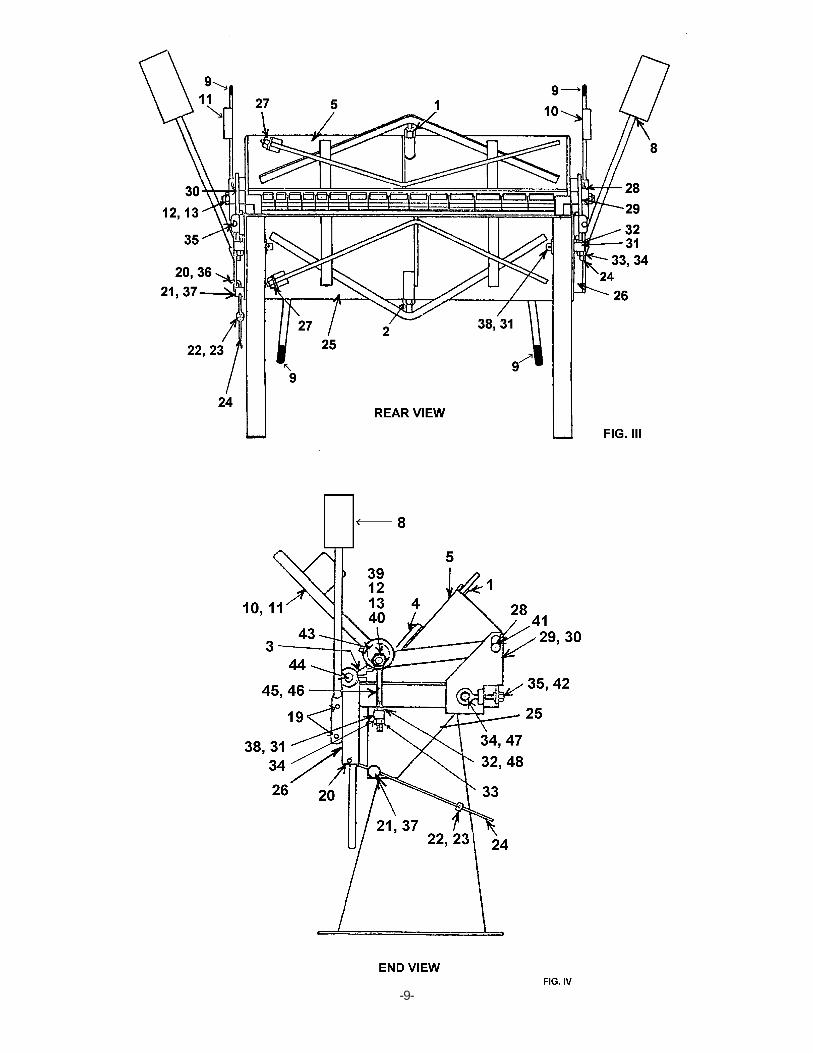
1. Relieve all tension on bed nut (No. 2) and set screw (No. 27).2. Raise the beam to its maximum height by means of eccentric levers (No. 10 & 11).3. Using an accurate spirit level or protractor head level on the bed bar (front of bed),
shim under the legs until the bed bar is level front to rear and lengthwise, with floor boltstightened against the shims.
The brake may change shape slightly in transit. Therefore, it is advisable to further check the level asfollows:
1. Relieve all tension on beam nuts (No. 1), and set screw (No. 27).2. Lower the beam onto the bed and loosen nut (No. 33) so there is 1/4” space between bottom of
pin (No. 31) and top surface of nut (No. 33).3. Starting with screws finger tight, take up screws (No. 27) about one full turn.4. Starting with nuts (No. 1 & 2) finger tight, take up each about 3/4 turn.5. Looking through from the rear of the brake, the beam and bed should be in contact at the center
and showing a crack of light at each end, as in Fig. 1. If there is less light showing at one end,loosen the rear floor bolt at that end and shim under the leg until light shows evenly at both ends.
6. The above steps should result in a level machine, but not necessarily the proper adjustment foryour work. To adjust for straight bending and uniform radius, follow the subsequentPRELOADING ADJUSTMENTS.
-6-

PRELOADING ADJUSTMENTS FOR FLOOR MODEL U412
Remove the shipping skids, bolt the brake to the floor, and level according to NOTES ON LEVELINGFLOOR MODEL U412.
Loosen strap bolt nuts (No. 1 & 2). Loosen tie rod screws (No. 27). Raise the beam to maximum heightby means of eccentric levers (No. 10 & 11).
The top edge of the apron should be 1/64” below the edge of the bed at the ends. If it is not, the hingebolts should be adjusted to bring the apron to this position. Tighten hinge bolts securely after thisadjustment.
Tighten apron strap bolt (No. 2) until the apron edge is 1/32” above the bed edge at the center. It shouldremain 1/64” below the bed at the ends.
Take up the tie rod screws (No. 27) about one full turn, starting with finger tight.
Tighten bed strap bolt (No. 2) until the edge of the bed is 1/64” above the top of the apron at center. Thisshould bring apron and bed parallel from end to end, with the bed 1/64” higher.
Beam preloading should be minimal in order to avoid counteracting the preload in the bed. Strap nuts(No. 1) may be tightened from 1/4 to 1/2 turn, starting with finger tight.
The brake now is adjusted for average work. When bending very light material, it may be necessary toreduce preloading in the bed and apron by slacking off strap nuts (No. 2). On full capacity work,preloading of bed and apron may be increased to tighten the bend radius at the center and produce astraight bend. Beam strap nut (No. 1) also is effective in tightening the radius at the center.
Hemming of heavy material may require adding pressure in the center of the beam by tightening nut(No. 1). Excessive clamping pressure by tightening nut (No. 33) will not help. It only defeats the purposeof preloading and puts extreme stress on the toggle (No. 45 & 46). No amount of preloading willcompensate for incorrect clamping pressure.
Follow carefully the general instructions for adjusting clamping pressure and clearances for variousthicknesses of material. Too little clearance results in sharp bends at the ends, larger radius at the cen-ter, and a bend that is not straight. It is better to accept a slightly greater radius in order to get a straightbend.
-7-

EXAGGERATED VIEW OF CROWNFROM REAR OF BRAKE
FIG. I
FIG. II
-8-
-9-

-10-

MODEL U412PARTS LIST
ITEM PART NO. PART NAME NO.
1 657023038 HEX NUT 7/8-9 2 657023038 HEX NUT 7/8-9 3 757360075 FINGER TIP 3” 3 757360076 FINGER TIP 4” 3 757360077 FINGER TIP 5” 4 757010078 FINGER HOLDER ASSY 3” 4 757010079 FINGER HOLDER ASSY 4” 4 757010080 FINGER HOLDER ASSY 5” 5 257020028 BEAM ASSY 6 621012269 SSCP SCREW 1/2-13 X 3/4 7 621012269 SSCP SCREW 1/2-13 X 3/4 8 757280074 COUNTER WEIGHT 9 657356334 PLASTIC BLACK GRIP10 757030003 RH CLAMPING LEVER11 757030004 LH CLAMPING LEVER12 678033112 FLAT WASHER 1”13 657245118 BEARING 1.0155 ID X 1.625 OD X 1/814 457500069 RH APRON HINGE15 457500070 LH APRON HINGE16 621012268 SSCP SCREW 1/2-13 X 5/817 601012271 HHC SCREW 1/2-13 X 1”18 757180069 BENDING ANGLE19 621012266 SSCP SCREW 1/2-13 X 1/220 600073501 COTTER PIN 3/32 X 1”21 757160038 STOP STUD APRON22 757260072 APRON STOP COLLAR23 621012125 SSCP SCREW 5/16-18 X 5/1624 757130036 APRON STOP ROD25 257090029 BED ASSY26 257020030 APRON ASSY27 657023038 HEX NUT 7/8-928 757080015 SLIDE PIN BUSHING29 757730006 LH SLIDE ASSY30 757730005 RH SLIDE ASSY31 757160096 LOWER TOGGLE PIN32 657033154 SPRING WASHER33 671023010 HEX NUT 3/4-1634 678033110 FLAT WASHER 3/435 611012418 SHC SCREW 3/4-10 X 3”
-11-

MODEL U412PARTS LIST
ITEM PART NO. PART NAME NO.
36 600083604 CLEVIS PIN37 666023007 HEX NYLOCK NUT 1/2-1338 757080018 LOWER TOGGLE PIN BUSHING39 679033112 LOCK WASHER40 657000390 CLAMPING COLLAR41 656164302 SNAP RING42 657000280 ADJUSTING SCREW COLLAR43 757080009 TOGGLE BUSHING44 757160011 HINGE PIN45 757860140 RH TOGGLE46 757860141 LH TOGGLE47 611012410 SHC SCREW 3/4-10 X 1 1/248 645023010 HEX NUT 3/4-1649 613012133 SHF SCREW 5/16-18 X 1”50 757030070 BENDING BAR51 613012128 SHF SCREW 5/16-18 X 1/2
-12-