model n, vsi, ivsi & zc single wall, double wall air ... · flange adapter (p-fd) 28 boiler kit...
TRANSCRIPT
INSTALLATION INSTRUCTIONS
& MAINTENANCE GUIDE
MODEL N, VSI, IVSI & ZC
SINGLE WALL, DOUBLE WALL AIR &
CERAMIC FIBER INSULATED POSITIVE PRESSURE PIPING SYSTEMS
www.ampcostacks.com 800.669.3269
BOILER STACK
ENGINE EXHAUST
GREASE DUCT
VENTILATION
DUCT
SPECIAL GAS VENT
TYPE BH VENT
TYPE L VENT
A MAJOR CAUSE OF CHIMNEY RELATED FIRES IS FAILURE TO MAINTAIN REQUIRED CLEARANCES (AIR SPACES) TO COMBUSTIBLE MATERIALS. IT IS OF UTMOST IMPORTANCE THAT THIS CHIMNEY BE INSTALLED IN ACCORDANCE WITH THESE INSTRUCTIONS.
2
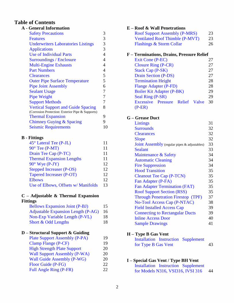
Table of Contents A - General Information
Safety Precautions 3
Features 3
Underwriters Laboratories Listings 3
Applications 3
Use of Individual Parts 4
Surroundings / Enclosure 4
Multi-Engine Exhausts 4
Part Numbers 4
Clearances 5
Outer Pipe Surface Temperature 5
Pipe Joint Assembly 6
Sealant Usage 7
Pipe Weight 7
Support Methods 7
Vertical Support and Guide Spacing (Corrosion Protection: Exterior Pipe & Supports)
8
Thermal Expansion 9
Chimney Guying & Spacing 9
Seismic Requirements 10
B - Fittings
45° Lateral Tee (P-JL) 11
90° Tee (P-MT) 11
Drain Tee Cap (P-TC) 11
Thermal Expansion Lengths 11
90° Wye (P-JY) 12
Stepped Increaser (P-OS) 12
Tapered Increaser (P-OT) 12
Elbows 12
Use of Elbows, Offsets w/ Manifolds 13
C – Adjustable & Thermal Expansion
Fittings
Bellows Expansion Joint (P-BJ) 15
Adjustable Expansion Length (P-AG) 16
Non-Exp Variable Length (P-VL) 18
Short & Odd Lengths 18
D – Structural Support & Guiding
Plate Support Assembly (P-PA) 19
Clamp Flange (P-CF) 19
High Strength Plate Support 20
Wall Support Assembly (P-WA) 20
Wall Guide Assembly (P-WG) 20
Floor Guide (P-FG) 22
Full Angle Ring (P-FR) 22
E – Roof & Wall Penetrations
Roof Support Assembly (P-MRS) 23
Ventilated Roof Thimble (P-MVT) 23
Flashings & Storm Collar 26
F – Terminations, Drains, Pressure Relief
Exit Cone (P-EC) 27
Closure Ring (P-CR) 27
Stack Cap (P-SK) 27
Drain Section (P-DS) 27
Termination Height 28
Flange Adapter (P-FD) 28
Boiler Kit Adapter (P-BK) 29
Seal Ring (P-SR) 29
Excessive Pressure Relief Valve
(P-ER)
30
G – Grease Duct
Listings 31
Surrounds 32
Clearances 32
Slope 32
Joint Assembly (regular pipes & adjustables) 33
Sealant 33
Maintenance & Safety 34
Automatic Cleaning 34
Fire Suppression 34
Hood Transition 35
Cleanout Tee Cap (P-TCN) 35
Fan Adapter (P-FA) 35
Fan Adapter Termination (FAT) 35
Roof Support Section (RSS) 35
Through Penetration Firestop (TPF) 37
No-Tool Access Cap (P-NTAC) 38
Field Installed Access Cap 39
Connecting to Rectangular Ducts 39
Inline Access Door 40
Sample Drawings 41
H – Type B Gas Vent
Installation Instruction Supplement
for Type B Gas Vent
43
I – Special Gas Vent / Type BH Vent
Installation Instruction Supplement
for Models N316, VSI316, IVSI 316
44
3
SAFETY PRECAUTIONS
Follow these instructions carefully. Failure to follow
these instructions could result in an unsafe installation. If you are
unsure of any instructions contact the factory at the number
indicated on the front page of these instructions.
A major cause of chimney/duct related fires is failure to
maintain required clearances (airspace) to combustible materials.
It is of utmost importance that this product be installed only in
accordance with these instructions.
Reference Combustion & Ventilation Air on page 30 for
proper air supply guidelines.
FEATURES
Model N, VSI and IVSI products are cylindrical, prefabricated,
modular venting systems incorporating flanged joints, designed
for both quick assembly and pressure sealing capability. Model
N is single wall vent. Model VSI is of double wall construction
incorporating a 1” airspace between walls and Model IVSI
incorporates 1” to 4” thick ceramic fiber insulation. Their
circular cross section and high quality stainless steel inner wall
construction provide for a system with high strength-to-weight
ratio and low friction losses.
UNDERWRITERS LABORATORIES LISTINGS
Ampco single wall Model N (aka VSI-I) and double wall models
VSI (aka VSI-II) and IVSI venting systems are Listed by
Underwriters Laboratories, Inc. (UL) under UL File MH6673 in
the following product categories and in the diameters indicated:
Model N (Single wall pipe) (aka VSI-1)
Grease Duct for Restaurant Cooking Appliances 5” - 48”ID
Chimney Liner – Gas/Oil- UL 1777 5”- 48” ID
Chimney Liner for Existing Masonry & Factory-Built
Chimneys- ULC S635 5” - 48”ID
Model VSI (Double wall, 1” air insulation) (aka VSI-II)
Building Heating Appliance Chimney 5”- 48” ID
1400° Fahrenheit Chimney 5”– 48”ID
Grease Duct for Restaurant Cooking Appliances 5” - 48”ID
Model IVSI (Double wall, 1, 2, 3 or 4” thick fiber insulation)
Building Heating Appliance Chimney 5”- 48”ID
1400° Fahrenheit Chimney 5”–48” ID
Building Heating Appliance Chimney(Type HT) 5”- 24”ID
Low Temperature Venting System, Type L 5” - 24”ID
Grease Duct for Restaurant Cooking Appliances 5” - 48”ID
Model N316, VSI316, IVSIS316
Special Gas Vent, Type BH Vent (UL 1738 & ULC-S636) 5” - 48” ID
APPLICATIONS
Building Heating Appliance Chimney Listing - Under this
category (UL 103, ULC/ORD-959), Model VSI and IVSI have
been determined suitable for venting flue gases at a temperature
not exceeding 1000°F, under continuous operating conditions,
from gas, liquid and solid fuel fired appliances. Intermittent
operation (less than one hour) at temperatures not exceeding
1400°F, and brief (maximum 10 minute) operation at
temperatures not exceeding 1700°F, is also permitted under this
application.
Building Heating Appliance Chimney (Type HT) Listing -
Under this category (UL 103HT), the 5” through 24” ID Model
IVSI has qualified for UL’s additional, optional “Type HT”
rating (for Building Heating Appliance Chimneys) which
indicates they have been evaluated and found suitable for
exposure to 2100°F flue gases for a 10 minute duration at 2”
airspace clearance to combustibles (unenclosed). Many local,
state and regional code authorities require a “Type HT” rating for
chimneys for certain appliance venting applications; especially
solid fuel.
Building Heating Appliance Chimneys are suitable for
use with Building Heating Appliances and other Low Heat
Appliances as described in the Chimney Selection Chart of
National Fire Protection Association (NFPA) Standard No. 211.
1400°F Chimney Listing - Under this category (UL 2561,
ULC/ORD-959), Model VSI and IVSI have been determined
suitable for venting flue gases continuously at a temperature not
exceeding 1400°F, and a 10 minute intermittent service at
temperatures not exceeding 1800°F. As such, Model VSI and
IVSI are suitable for use with ovens and furnaces as described in
the Chimney Selection Chart of NFPA No. 211, in addition to
other Applications.
Low Temperature Venting System, Type L (L-Vent) Listing -
Under this category (UL 641), 5” through 24” ID Model IVSI
has been determined suitable for use with gas and oil fueled
appliances Listed as suitable for venting with Type L or Type B
venting systems. This qualifies the system for handling
continuous flue gas temperatures at a maximum of 480°F above
ambient, and permits full enclosure in combustible chase
construction, assuming the specified minimum airspace
clearance-to-combustibles is maintained.
Grease Duct for Commercial Cooking Appliances Listing -
Applications and instructions for this category (UL 1978) are
covered in Section “G” entitled “Grease Duct”.
Type B Gas Vent – Applications and instructions for this
category (UL 441) are covered in section “H” entitled “Type B
Gas Vent” for models VSI and IVSI.
Special Gas Vent & Type BH Vent Listing – Applications and
instructions for this category (UL 1738 & ULC-S636) are
covered in Section “I” entitled “Special Gas Vent” for models
N316, VSI316 and IVSI316.
GENERAL INFORMATION
Installation Instructions
Section A
! WARNING
Failure to follow these Installation Instructions could cause
FIRE, CARBON MONOXIDE POISONING, OR DEATH.
If you are unsure of Installation requirements, call the
Phone Number listed on the front of these instructions.
Caution-Risk of injury. Sheet metal parts may be
sharp. Always wear gloves and appropriate eye, foot, and
other protection when handling these products.
4
Based upon the above referenced UL Listings and
supplemental, UL confirmed pressure testing (up to +60”w.c. at
1000oF), Model N, VSI and IVSI are also suitable for use as
complete exhaust systems for diesel engine and gas turbines.
When Model VSI/IVSI is used as an engine or turbine exhaust it
is intended to be installed in accordance with NFPA 37
“Stationary Combustion Engines and Gas Turbines”.
MULTI-ENGINE EXHAUSTS: A common exhaust
system for multiple engine or turbine installations is not
recommended. Check with your engine or turbine manufacturer
prior to common exhaust system design. Exhaust gas from
operating units tends to flow to non-operating units where
condensation may form. Water in engine or turbines at start-up
may cause damage. In general, a separate exhaust system should
be provided for each engine or turbine.
Model IVSI may be used to meet various needs, such as:
a) Reduce outer pipe surface temperature.
b) Reduce building heat gain by retaining energy inside the
duct.
c) Increase the efficiency of energy recovery systems by
reducing exhaust gas temperature losses.
d) Increase chimney or exhaust system draft loss performance
due to reduced exhaust gas temperature drop.
e) Reduce building noise levels caused by high speed or
pulsating exhaust induced noise. NOTE: Specific tests have
not been conducted to measure acoustic performance.
Model VSI and IVSI exhaust systems are intended for use in
connecting the appliance exhaust to the outdoors (including
exterior runs of pipe (ie. Alongside a building or on the roof)),
while operating under positive forced draft, negative induced
draft or neutral gravity flow internal pressure conditions.
Model VSI and IVSI (all insulation thicknesses) may be
intermixed in the same chimney system, assuming the proper
associated airspace clearances-to-combustibles are maintained.
Complete system sizing and capacity information may be
obtained from the “Chimney, Gas Vent, and Fireplace Systems”
chapter of the ASHRAE Handbook, or by contacting Ampco
Technical Support. In spite of these general sizing guidelines, it
is most important that the heating appliance, engine or turbine
manufacturer’s installation instructions are followed. Not
following the equipment manufacturer’s instructions may result
in inadequate chimney performance and/or a violation of the
equipment manufacturer’s installation requirements.
ADDITIONAL APPLICATIONS
Model N, VSI & IVSI are also suitable for negative, neutral or
positive pressure pre-fabricated piping systems intended for use
in a variety of applications including but not limited to the
following: Fume Venting, Chutes, Particle Conveying, Dryer
Vents and Ventilation Ducts.
CREOSOTE AND SOOT – FORMATION AND NEED FOR
REMOVAL
When wood is burned slowly, it produces tar, moisture
and other organic vapors which combine to form creosote, a
substance that can self-ignite and cause very hot chimney fires if
not maintained. The chimney should be professionally inspected,
periodically, during seasons of operation to determine if creosote
buildup has occurred and in need of professional cleaning.
Refer to Elbow & Offset section for additional
limitations with regards to burning solid fuel.
USE OF INDIVIDUAL PARTS
These instructions comprise both general guidelines and
special requirements for all parts in the product line. Before
specifying a design or beginning an installation please carefully
review these instructions.
SURROUNDINGS / ENCLOSURE
Ampco Model N, VSI and IVSI chimneys are primarily
intended to be used in fire resistive, noncombustible
surroundings or installed unenclosed. Except as noted elsewhere
in these instructions, they are not intended for use in one or two
family residences. (CAUTION — Do not enclose these systems
in a chase or passageway of ordinary wood or other combustible
material, unless noted as acceptable elsewhere in these
instructions for a specific application.)
For Type L Vent installations, Model IVSI may be
enclosed within a chase fabricated from combustible building
materials. Check local codes to determine the required fire
rating, if any, for such chase enclosures.
Where the chimney extends through any zone of a
building (outside that in which the heating appliance connected
to it is located), it shall be provided with an enclosure having a
fire resistance rating equal to or greater than that of the floor,
ceiling, wall or roof assemblies through which it passes.
Model VSI and IVSI Chimney may penetrate a
combustible roof using either the Roof Support Assembly (P-
MRS) or the Ventilated Roof Thimble (P-MVT). These are the
only parts intended for use with combustible construction. All
other parts, such as Plate and Wall Supports, and Floor and Wall
Guides, are for attachment to non-combustible construction.
Where, according to local code, no chase enclosure is
necessary, Model VSI and IVSI may be placed adjacent to walls
of combustible construction at the minimum clearance specified
on each pipe section and in the individual Listing; see
CLEARANCES section and Tables A-1a through A-1d. Contact
local building or fire officials about restrictions and installation
inspection requirements in your area.
PART NUMBERS
These instructions identify major Model N, VSI and IVSI parts
by name or part number. Actual parts always carry a prefix to
indicate internal diameter and either the letter “N” for Model N,
“VSI” for model VSI or “IVSI” for model IVSI. Model IVSI also
includes a suffix to indicate insulation thickness. For example:
24VSI-42 is a 24 inch diameter of model VSI, 42 inches in
length; 24IVSI-42C2 is a 24 inch diameter section of Model
IVSI, 42 inches long having 2 inches of fiber insulation between
the walls.
For approved Special Gas Vent applications, the
designation ‘316’ will immediately follow N, VSI, IVSI (ie.
24IVSI316-42C2).
5
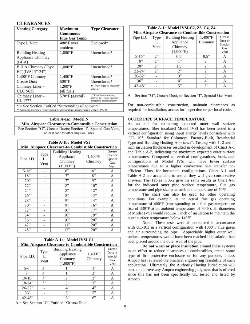
CLEARANCES Venting Category Maximum
Continuous
Flue Gas Temp
Type Clearance
Type L Vent 480°F over
ambient
Enclosed*
Building Heating
Appliance Chimney
(BHA)
1,000°F Unenclosed*
B.H.A Chimney (Type
HT)(IVSI 5”-24”)
1,000°F Unenclosed*
1,400°F Chimney 1,400°F Unenclosed*
Grease Duct 500°F Unenclosed*
Chimney Liner –
ULC S635
1200°F
(all fuel)
0” from liner to masonry
interior
Chimney Liner –
UL 1777
570°F (gas/oil) 1” from liner to masonry
interior & 1” from masonry
exterior to combustibles**
* = See Section Entitled “Surroundings/Enclosure” ** Masonry chimney construction & surroundings must comply with NFPA 211
Table A-1a: Model N
Min. Airspace Clearance-to-Combustible Construction
See Section “G”, Grease Ducts; Section ‘I’, Special Gas Vent, or local code for other singlewall uses
Table A-1b: Model VSI
Min. Airspace Clearance-to-Combustible Construction
Pipe I.D.
Type
L
Vent
Building Heating
Appliance
Chimney
(1,000°F)
1,400°F
Chimney
Grease
Duct or
Special Gas
Vent
5-16” - 6” 6” A
18” - 7” 8” A
20” - 7” 9” A
22” - 8” 10” A
24” - 8” 12” A
26” - 8” 13” A
28” - 9” 14” A
30” - 9” 16” A
32” - 10” 17” A
34” - 10” 19” A
36” - 10” 20” A
42” - 11” 20” A
48” - 12” 20” A
Table A-1c: Model IVSI-C1
Min. Airspace Clearance-to-Combustible Construction
Pipe I.D.
Type
L
Vent
Building Heating
Appliance
Chimney
(1,000°F)
1,400°F
Chimney
Grease Duct or
Special
Gas Vent
5-6” 3” 1” 1” A
8” 3” 1” 2” A
10-16” 3” 2” 2” A
18-24” 3” 3” 3” A
26-32” - 4” 4” A
36” - 5” 5” A
42-48” - 6” 6” A
A = See Section “G” Entitled “Grease Duct”
Table A-1: Model IVSI-C2, Z3, C4, Z4
Min. Airspace Clearance-to-Combustible Construction
Pipe I.D. Type
L
Vent
Building Heating
Appliance
Chimney
(1,000°F)
1,400°F
Chimney
Grease Duct or
Special
Gas Vent
5-16” 2” 0.5” 0.5” A
18” 2” 1” 2” A
20” 2” 1.5” 2” A
22-24” 2” 2” 2” A
26-32” - 3” 3” A
36” - 4” 4” A
42-48” - 5” 5” A
A = Section “G”, Grease Duct, or Section “I”, Special Gas Vent
For non-combustible construction, maintain clearances as
required for installation, access for inspection or per local code.
OUTER PIPE SURFACE TEMPERATURE
As an aid for estimating expected outer wall surface
temperatures, fiber insulated Model IVSI has been tested in a
vertical configuration using input energy levels consistent with
“UL 103; Standard for Chimneys, Factory-Built, Residential
Type and Building Heating Appliance”. Testing with 1, 2 and 4
inch insulation thicknesses resulted in development of Chart A-1
and Table A-2, indicating the maximum expected outer surface
temperatures. Compared to vertical configurations, horizontal
configurations of Model IVSI will have lower surface
temperatures due to a higher convective heat transfer co-
efficient. Thus, for horizontal configurations, Chart A-1 and
Table A-2 are acceptable to use as they will give conservative
answers. The Tables in A-2 give the same results as Chart A-1
for the indicated outer pipe surface temperature, flue gas
temperature and pipe size at an ambient temperature of 70°F.
The chart can also be used for other operating
conditions. For example, at an actual flue gas operating
temperature of 400°F (corresponding to a flue gas temperature
rise of 330°F at an ambient temperature of 70°F), all diameters
of Model IVSI would require 1 inch of insulation to maintain the
outer surface temperature below 140°F.
Note: These tests were all conducted in accordance
with UL-103 in a vertical configuration with 1000°F flue gases
and air surrounding the pipe. Appreciable higher outer wall
surface temperatures would have been reached if insulation had
been placed around the outer wall of the pipe.
Do not wrap or place insulation around these systems
in an effort to reduce clearances to combustibles, create some
type of fire protective enclosure or for any purpose, unless
Ampco has reviewed the practical engineering feasibility of such
application. Ultimately, the Authority Having Jurisdiction will
need to approve any Ampco engineering judgment that is offered
since this has not been specifically UL tested and listed by
Ampco.
6
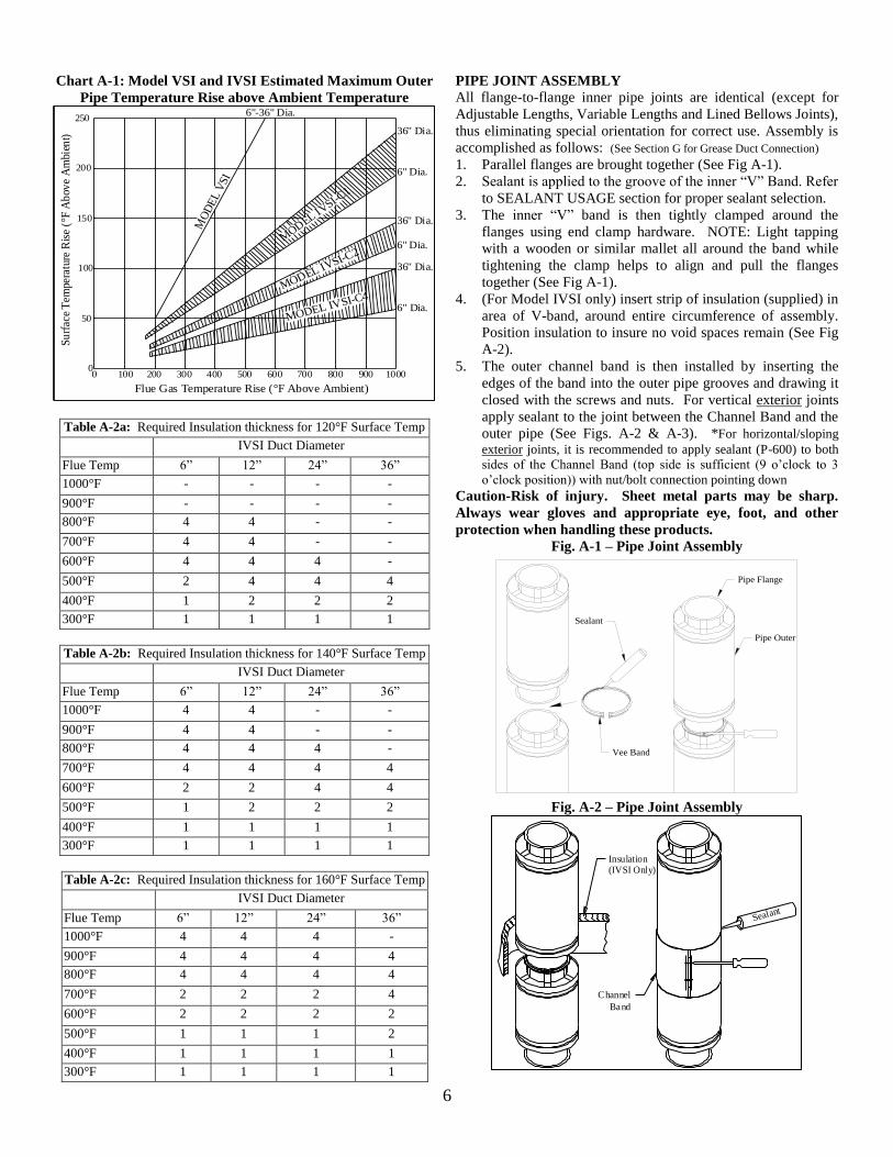
Chart A-1: Model VSI and IVSI Estimated Maximum Outer
Pipe Temperature Rise above Ambient Temperature
Su
rfac
e T
empe
ratu
re R
ise
(°F
Ab
ove
Am
bien
t)
Flue Gas Temperature Rise (°F Above Ambient)
MODEL IVSI-C4MODEL IV
SI-C2
MOD
EL IVSI-C
1
6" Dia.
36" Dia.
6" Dia.
36" Dia.
6" Dia.
36" Dia.
6"-36" Dia.250
200
150
100
50
00 1000900800700600500400300200100
MO
DE
L V
SI
Table A-2a: Required Insulation thickness for 120°F Surface Temp
IVSI Duct Diameter
Flue Temp 6” 12” 24” 36”
1000°F - - - -
900°F - - - -
800°F 4 4 - -
700°F 4 4 - -
600°F 4 4 4 -
500°F 2 4 4 4
400°F 1 2 2 2
300°F 1 1 1 1
Table A-2b: Required Insulation thickness for 140°F Surface Temp
IVSI Duct Diameter
Flue Temp 6” 12” 24” 36”
1000°F 4 4 - -
900°F 4 4 - -
800°F 4 4 4 -
700°F 4 4 4 4
600°F 2 2 4 4
500°F 1 2 2 2
400°F 1 1 1 1
300°F 1 1 1 1
Table A-2c: Required Insulation thickness for 160°F Surface Temp
IVSI Duct Diameter
Flue Temp 6” 12” 24” 36”
1000°F 4 4 4 -
900°F 4 4 4 4
800°F 4 4 4 4
700°F 2 2 2 4
600°F 2 2 2 2
500°F 1 1 1 2
400°F 1 1 1 1
300°F 1 1 1 1
PIPE JOINT ASSEMBLY
All flange-to-flange inner pipe joints are identical (except for
Adjustable Lengths, Variable Lengths and Lined Bellows Joints),
thus eliminating special orientation for correct use. Assembly is
accomplished as follows: (See Section G for Grease Duct Connection)
1. Parallel flanges are brought together (See Fig A-1).
2. Sealant is applied to the groove of the inner “V” Band. Refer
to SEALANT USAGE section for proper sealant selection.
3. The inner “V” band is then tightly clamped around the
flanges using end clamp hardware. NOTE: Light tapping
with a wooden or similar mallet all around the band while
tightening the clamp helps to align and pull the flanges
together (See Fig A-1).
4. (For Model IVSI only) insert strip of insulation (supplied) in
area of V-band, around entire circumference of assembly.
Position insulation to insure no void spaces remain (See Fig
A-2).
5. The outer channel band is then installed by inserting the
edges of the band into the outer pipe grooves and drawing it
closed with the screws and nuts. For vertical exterior joints
apply sealant to the joint between the Channel Band and the
outer pipe (See Figs. A-2 & A-3). *For horizontal/sloping
exterior joints, it is recommended to apply sealant (P-600) to both
sides of the Channel Band (top side is sufficient (9 o’clock to 3
o’clock position)) with nut/bolt connection pointing down
Caution-Risk of injury. Sheet metal parts may be sharp.
Always wear gloves and appropriate eye, foot, and other
protection when handling these products.
Fig. A-1 – Pipe Joint Assembly
Sealant
Vee Band
Pipe Flange
Pipe Outer
Fig. A-2 – Pipe Joint Assembly
Insulation(IVSI Only)
Channel
Band
Sealant
7
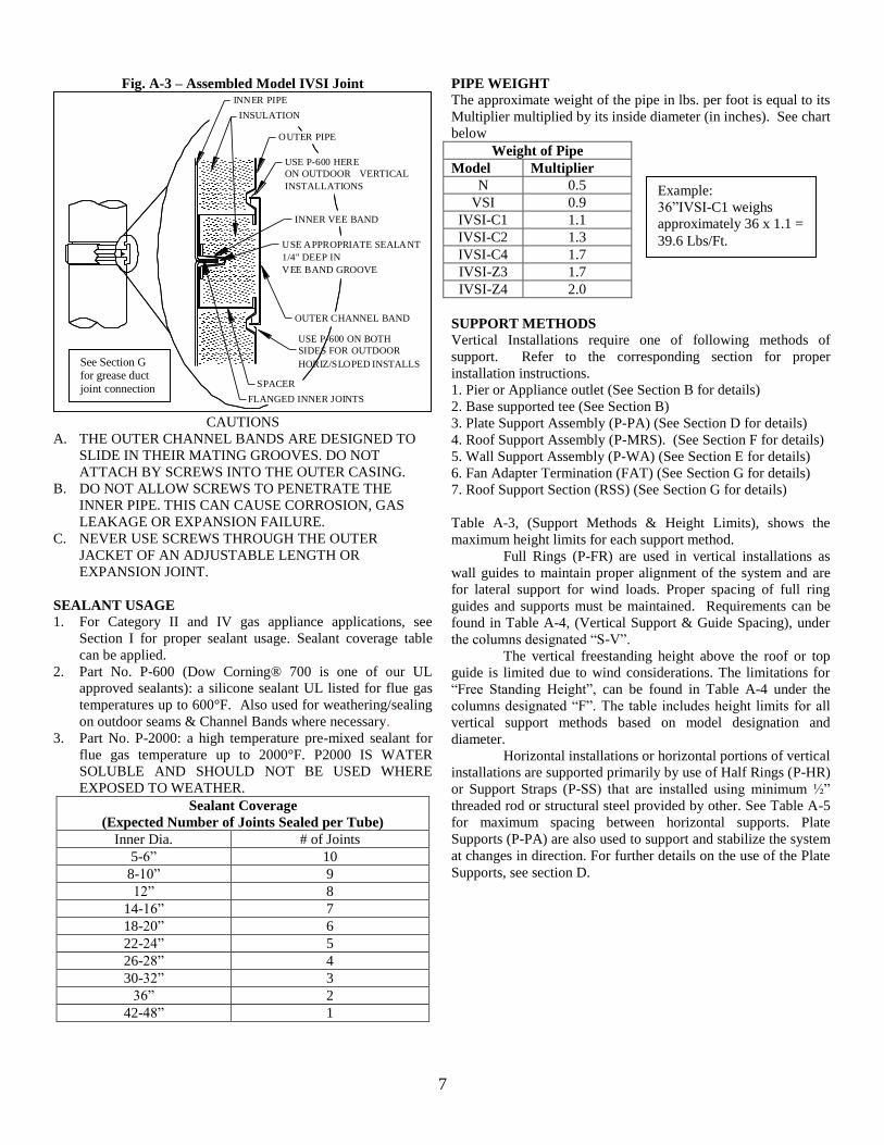
Fig. A-3 – Assembled Model IVSI Joint
USE P-600 ON BOTH
HORIZ/SLOPED INSTALLS
SIDES FOR OUTDOOR
OUTER PIPE
VEE BAND GROOVE
VERTICAL
USE P-600 HERE
1/4" DEEP IN
USE APPROPRIATE SEALANT
INSTALLATIONS
ON OUTDOOR
OUTER CHANNEL BAND
INNER VEE BAND
INSULATION
INNER PIPE
FLANGED INNER JOINTS
SPACER
CAUTIONS
A. THE OUTER CHANNEL BANDS ARE DESIGNED TO
SLIDE IN THEIR MATING GROOVES. DO NOT
ATTACH BY SCREWS INTO THE OUTER CASING.
B. DO NOT ALLOW SCREWS TO PENETRATE THE
INNER PIPE. THIS CAN CAUSE CORROSION, GAS
LEAKAGE OR EXPANSION FAILURE.
C. NEVER USE SCREWS THROUGH THE OUTER
JACKET OF AN ADJUSTABLE LENGTH OR
EXPANSION JOINT.
SEALANT USAGE
1. For Category II and IV gas appliance applications, see
Section I for proper sealant usage. Sealant coverage table
can be applied.
2. Part No. P-600 (Dow Corning® 700 is one of our UL
approved sealants): a silicone sealant UL listed for flue gas
temperatures up to 600°F. Also used for weathering/sealing
on outdoor seams & Channel Bands where necessary.
3. Part No. P-2000: a high temperature pre-mixed sealant for
flue gas temperature up to 2000°F. P2000 IS WATER
SOLUBLE AND SHOULD NOT BE USED WHERE
EXPOSED TO WEATHER.
Sealant Coverage
(Expected Number of Joints Sealed per Tube)
Inner Dia. # of Joints
5-6” 10
8-10” 9
12” 8
14-16” 7
18-20” 6
22-24” 5
26-28” 4
30-32” 3
36” 2
42-48” 1
PIPE WEIGHT
The approximate weight of the pipe in lbs. per foot is equal to its
Multiplier multiplied by its inside diameter (in inches). See chart
below
Weight of Pipe
Model Multiplier
N 0.5
VSI 0.9
IVSI-C1 1.1
IVSI-C2 1.3
IVSI-C4 1.7
IVSI-Z3 1.7
IVSI-Z4 2.0
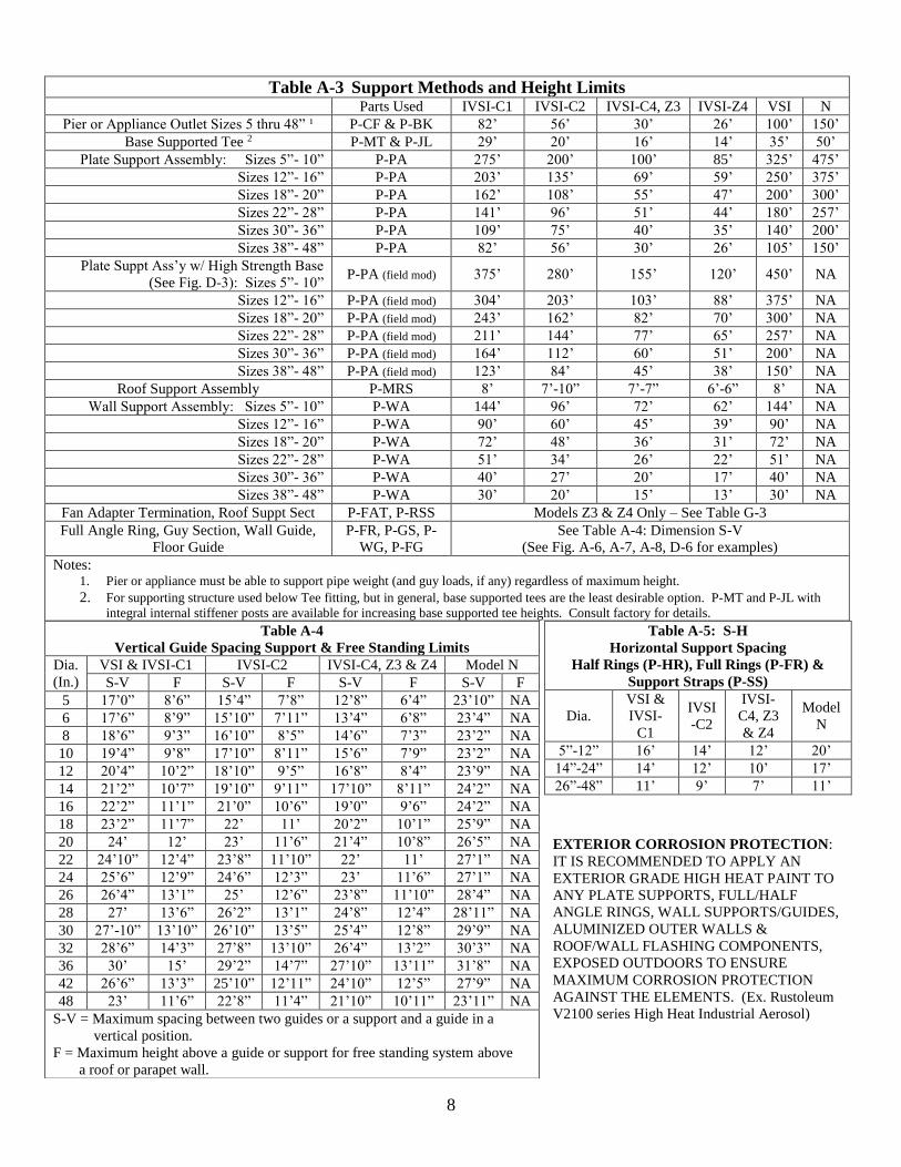
SUPPORT METHODS
Vertical Installations require one of following methods of
support. Refer to the corresponding section for proper
installation instructions.
1. Pier or Appliance outlet (See Section B for details)
2. Base supported tee (See Section B)
3. Plate Support Assembly (P-PA) (See Section D for details)
4. Roof Support Assembly (P-MRS). (See Section F for details)
5. Wall Support Assembly (P-WA) (See Section E for details)
6. Fan Adapter Termination (FAT) (See Section G for details)
7. Roof Support Section (RSS) (See Section G for details)
Table A-3, (Support Methods & Height Limits), shows the
maximum height limits for each support method.
Full Rings (P-FR) are used in vertical installations as
wall guides to maintain proper alignment of the system and are
for lateral support for wind loads. Proper spacing of full ring
guides and supports must be maintained. Requirements can be
found in Table A-4, (Vertical Support & Guide Spacing), under
the columns designated “S-V”.
The vertical freestanding height above the roof or top
guide is limited due to wind considerations. The limitations for
“Free Standing Height”, can be found in Table A-4 under the
columns designated “F”. The table includes height limits for all
vertical support methods based on model designation and
diameter.
Horizontal installations or horizontal portions of vertical
installations are supported primarily by use of Half Rings (P-HR)
or Support Straps (P-SS) that are installed using minimum ½”
threaded rod or structural steel provided by other. See Table A-5
for maximum spacing between horizontal supports. Plate
Supports (P-PA) are also used to support and stabilize the system
at changes in direction. For further details on the use of the Plate
Supports, see section D.
Example:
36”IVSI-C1 weighs
approximately 36 x 1.1 =
39.6 Lbs/Ft.
See Section G for grease duct
joint connection
8
Table A-5: S-H
Horizontal Support Spacing
Half Rings (P-HR), Full Rings (P-FR) &
Support Straps (P-SS)
Dia.
VSI &
IVSI-
C1
IVSI
-C2
IVSI-
C4, Z3
& Z4
Model
N
5”-12” 16’ 14’ 12’ 20’
14”-24” 14’ 12’ 10’ 17’
26”-48” 11’ 9’ 7’ 11’
EXTERIOR CORROSION PROTECTION:
IT IS RECOMMENDED TO APPLY AN
EXTERIOR GRADE HIGH HEAT PAINT TO
ANY PLATE SUPPORTS, FULL/HALF
ANGLE RINGS, WALL SUPPORTS/GUIDES,
ALUMINIZED OUTER WALLS &
ROOF/WALL FLASHING COMPONENTS,
EXPOSED OUTDOORS TO ENSURE
MAXIMUM CORROSION PROTECTION
AGAINST THE ELEMENTS. (Ex. Rustoleum
V2100 series High Heat Industrial Aerosol)
Table A-3 Support Methods and Height Limits Parts Used IVSI-C1 IVSI-C2 IVSI-C4, Z3 IVSI-Z4 VSI N
Pier or Appliance Outlet Sizes 5 thru 48” ¹ P-CF & P-BK 82’ 56’ 30’ 26’ 100’ 150’
Base Supported Tee 2 P-MT & P-JL 29’ 20’ 16’ 14’ 35’ 50’
Plate Support Assembly: Sizes 5”- 10” P-PA 275’ 200’ 100’ 85’ 325’ 475’
Sizes 12”- 16” P-PA 203’ 135’ 69’ 59’ 250’ 375’
Sizes 18”- 20” P-PA 162’ 108’ 55’ 47’ 200’ 300’
Sizes 22”- 28” P-PA 141’ 96’ 51’ 44’ 180’ 257’
Sizes 30”- 36” P-PA 109’ 75’ 40’ 35’ 140’ 200’
Sizes 38”- 48” P-PA 82’ 56’ 30’ 26’ 105’ 150’
Plate Suppt Ass’y w/ High Strength Base
(See Fig. D-3): Sizes 5”- 10” P-PA (field mod) 375’ 280’ 155’ 120’ 450’ NA
Sizes 12”- 16” P-PA (field mod) 304’ 203’ 103’ 88’ 375’ NA
Sizes 18”- 20” P-PA (field mod) 243’ 162’ 82’ 70’ 300’ NA
Sizes 22”- 28” P-PA (field mod) 211’ 144’ 77’ 65’ 257’ NA
Sizes 30”- 36” P-PA (field mod) 164’ 112’ 60’ 51’ 200’ NA
Sizes 38”- 48” P-PA (field mod) 123’ 84’ 45’ 38’ 150’ NA
Roof Support Assembly P-MRS 8’ 7’-10” 7’-7” 6’-6” 8’ NA
Wall Support Assembly: Sizes 5”- 10” P-WA 144’ 96’ 72’ 62’ 144’ NA
Sizes 12”- 16” P-WA 90’ 60’ 45’ 39’ 90’ NA
Sizes 18”- 20” P-WA 72’ 48’ 36’ 31’ 72’ NA
Sizes 22”- 28” P-WA 51’ 34’ 26’ 22’ 51’ NA
Sizes 30”- 36” P-WA 40’ 27’ 20’ 17’ 40’ NA
Sizes 38”- 48” P-WA 30’ 20’ 15’ 13’ 30’ NA
Fan Adapter Termination, Roof Suppt Sect P-FAT, P-RSS Models Z3 & Z4 Only – See Table G-3
Full Angle Ring, Guy Section, Wall Guide,
Floor Guide
P-FR, P-GS, P-
WG, P-FG
See Table A-4: Dimension S-V
(See Fig. A-6, A-7, A-8, D-6 for examples)
Notes: 1. Pier or appliance must be able to support pipe weight (and guy loads, if any) regardless of maximum height.
2. For supporting structure used below Tee fitting, but in general, base supported tees are the least desirable option. P-MT and P-JL with
integral internal stiffener posts are available for increasing base supported tee heights. Consult factory for details.
Table A-4
Vertical Guide Spacing Support & Free Standing Limits
Dia.
(In.)
VSI & IVSI-C1 IVSI-C2 IVSI-C4, Z3 & Z4 Model N
S-V F S-V F S-V F S-V F
5 17’0” 8’6” 15’4” 7’8” 12’8” 6’4” 23’10” NA
6 17’6” 8’9” 15’10” 7’11” 13’4” 6’8” 23’4” NA
8 18’6” 9’3” 16’10” 8’5” 14’6” 7’3” 23’2” NA
10 19’4” 9’8” 17’10” 8’11” 15’6” 7’9” 23’2” NA
12 20’4” 10’2” 18’10” 9’5” 16’8” 8’4” 23’9” NA
14 21’2” 10’7” 19’10” 9’11” 17’10” 8’11” 24’2” NA
16 22’2” 11’1” 21’0” 10’6” 19’0” 9’6” 24’2” NA
18 23’2” 11’7” 22’ 11’ 20’2” 10’1” 25’9” NA
20 24’ 12’ 23’ 11’6” 21’4” 10’8” 26’5” NA
22 24’10” 12’4” 23’8” 11’10” 22’ 11’ 27’1” NA
24 25’6” 12’9” 24’6” 12’3” 23’ 11’6” 27’1” NA
26 26’4” 13’1” 25’ 12’6” 23’8” 11’10” 28’4” NA
28 27’ 13’6” 26’2” 13’1” 24’8” 12’4” 28’11” NA
30 27’-10” 13’10” 26’10” 13’5” 25’4” 12’8” 29’9” NA
32 28’6” 14’3” 27’8” 13’10” 26’4” 13’2” 30’3” NA
36 30’ 15’ 29’2” 14’7” 27’10” 13’11” 31’8” NA
42 26’6” 13’3” 25’10” 12’11” 24’10” 12’5” 27’9” NA
48 23’ 11’6” 22’8” 11’4” 21’10” 10’11” 23’11” NA
S-V = Maximum spacing between two guides or a support and a guide in a
vertical position.
F = Maximum height above a guide or support for free standing system above
a roof or parapet wall.
9
THERMAL EXPANSION
Good installation practice requires that any length of
exhaust system between two fixed points subject to more than
1/4 inch expansion must have an Adjustable Length (P-AG) or
Bellows Joint (P-BJ) to compensate for expansion. VSI/IVSI will
expand approximately 1 inch for every 100°F temperature rise
per 100 feet of pipe.
For Grease Duct applications any length over 12 feet
installed between two fixed points i.e.: Hood Outlet and Elbow,
Plate and Wall Support, etc., must be provided with an
Adjustable Length (P-AG) to compensate for expansion and
contraction.
It is essential that these parts be properly installed and
provided with adequate guidance to prevent binding or excessive
bending forces. (See detailed installation information contained
in Section C, Thermal Expansion.)
The exhaust system designer must be aware that the
inner joints have negligible flexing capability, and in addition,
Tees and Elbows are not designed to withstand excessive
bending forces. Because the amount of outer casing axial
movement is less than the inner casing movement, but still
significant, the outer jackets of piping and Adjustable Lengths
must also slide to avoid excessive forces on Tees, Elbows or
Fixed Joints. To accommodate outer casing movements, external
guides along walls, at floors, or in lateral breechings, must allow
for movement of the pipe. Further; Full/Half Rings, Wall Guides
or Floor Guides must be so located that Outer Channel Band
movements will be away from the ring.
CHIMNEY GUYING AND BRACING
Model N, VSI, IVSI, Z3 & Z4 Grease Duct has thin
pipe walls relative to its diameter (t/D<0.006 for all sizes) and
has the characteristics of a continuous pipe of 300 Series
Stainless Steel. Therefore it will expand and contract along its
entire length with changes in temperature. Thus, unless properly
supported and guided, structural damage to the exhaust system
will occur. For these reasons, conventional methods of attaching
guides and braces to the outer pipe cannot be used. Correctly
installed Angle Rings (P-FR and P-HR), Wall Guides (P-WG),
Floor Guides (P-FG), Guy Sections (P-GS), Plate Support
Assemblies (P-PA) and Wall Support Assemblies (P-WA) will
serve to keep the chimney aligned and supported, provide for
adequate wind load resistance and allow for axial thermal
expansion and contraction.
Stabilization of the part of the chimney which extends
above the roof or a parapet wall requires special consideration.
For low, freestanding installations (up to Dimension F in Table
A-4) the chimney needs no special guying or bracing. However,
to protect the roof flashings from loads caused by wind against
the exposed chimney, the installation must be stabilized with a
Full Angle Ring (P-FR) as illustrated in Fig. A-6.
In addition to the requirement for alignment and
stabilization of the chimney, the need often exists for guying or
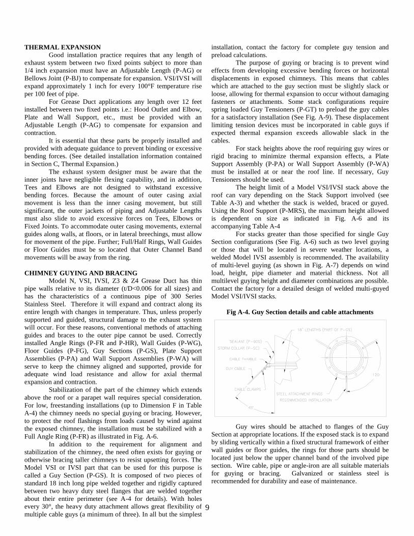
otherwise bracing taller chimneys to resist upsetting forces. The
Model VSI or IVSI part that can be used for this purpose is
called a Guy Section (P-GS). It is composed of two pieces of
standard 18 inch long pipe welded together and rigidly captured
between two heavy duty steel flanges that are welded together
about their entire perimeter (see A-4 for details). With holes
every 30°, the heavy duty attachment allows great flexibility of
multiple cable guys (a minimum of three). In all but the simplest
installation, contact the factory for complete guy tension and
preload calculations.
The purpose of guying or bracing is to prevent wind
effects from developing excessive bending forces or horizontal
displacements in exposed chimneys. This means that cables
which are attached to the guy section must be slightly slack or
loose, allowing for thermal expansion to occur without damaging
fasteners or attachments. Some stack configurations require
spring loaded Guy Tensioners (P-GT) to preload the guy cables
for a satisfactory installation (See Fig. A-9). These displacement
limiting tension devices must be incorporated in cable guys if
expected thermal expansion exceeds allowable slack in the
cables.
For stack heights above the roof requiring guy wires or
rigid bracing to minimize thermal expansion effects, a Plate
Support Assembly (P-PA) or Wall Support Assembly (P-WA)
must be installed at or near the roof line. If necessary, Guy
Tensioners should be used.
The height limit of a Model VSI/IVSI stack above the
roof can vary depending on the Stack Support involved (see
Table A-3) and whether the stack is welded, braced or guyed.
Using the Roof Support (P-MRS), the maximum height allowed
is dependent on size as indicated in Fig. A-6 and its
accompanying Table A-4
For stacks greater than those specified for single Guy
Section configurations (See Fig. A-6) such as two level guying
or those that will be located in severe weather locations, a
welded Model IVSI assembly is recommended. The availability
of multi-level guying (as shown in Fig. A-7) depends on wind
load, height, pipe diameter and material thickness. Not all
multilevel guying height and diameter combinations are possible.
Contact the factory for a detailed design of welded multi-guyed
Model VSI/IVSI stacks.
Fig A-4. Guy Section details and cable attachments
Guy wires should be attached to flanges of the Guy
Section at appropriate locations. If the exposed stack is to expand
by sliding vertically within a fixed structural framework of either
wall guides or floor guides, the rings for those parts should be
located just below the upper channel band of the involved pipe
section. Wire cable, pipe or angle-iron are all suitable materials
for guying or bracing. Galvanized or stainless steel is
recommended for durability and ease of maintenance.
10
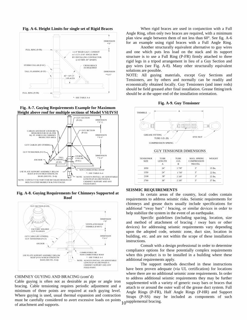
Fig. A-6. Height Limits for single set of Rigid Braces
FULL RING (P-FR)
STORM COLLAR (P-SC)
TALL FLASHING (P-TF)
FULL RING (P-FR)
DIMENSION
DIMENSION
*"S-V"
*"F"
AS REQUIREDCROSS BRACE
* - SEE TABLE A-4
(2 AT MIN. 60° APART)
2-PLACES
45° +10°/-5°
BY INSTALLING CONTRACTOR.
or 1-1/2"x 3/16" ANGLE IRON
1-1/4" RIGID GALV. CONDUIT
Fig. A-7. Guying Requirements Example for Maximum
Height above roof for multiple sections of Model VSI/IVSI
BASE (SEE FIG. D-4))
ROOF (P-PA W/HIGH STRENGTHUSE PLATE SUPPORT ASSEMBLY BELOW
DIMENSION
DIMENSION
DIMENSION(P-GS)
GUY SECTION
ANCHOR
GUY TENSIONER (P-GT)
PROJECTED AREA.SQ. FT. FORCE ON CHIMNEY
DESIGNED FOR 30 LB. PERCABLES AND ROOF ANCHORS
*"S-V"
*"F"/2
*"S-V"
NON-COMBUSTIBLE ROOF
(P-TF)
FLASHINGTALL
(P-SC)
COLLARSTORM
(P-GS)
GUY SECTION
GUY CABLES (BY OTHERS)
MULTI-GUYED MODELVSI & IVSI STACKS
CONTACT FACTORY FOR DETAILED DESIGNS OFNOTE:
FIXED POINT.
CHIMNEY SUPPORT AND ANY
LENGTH (P-AG) BETWEEN AALWAYS INSTALL AN ADJUSTABLENOTE:
* - SEE TABLE A-4
Fig. A-8. Guying Requirements for Chimneys Supported at
Roof
GUY SECTION (P-GS)
BASE (SEE FIG. D-4))
ROOF (P-PA W/HIGH STRENGTHUSE PLATE SUPPORT ASSEMBLY BELOW
DIMENSION
DIMENSION
ANCHOR
GUY TENSIONER (P-GT) *"S-V"
*"F"
NON-COMBUSTIBLE ROOFCOMBUSTIBLE OR
THIMBLE (P-MVT)
VENTILATED ROOF
GUY CABLE (BY OTHERS)
GUY FLANGESFACTORY WELDED
FIXED POINT.
CHIMNEY SUPPORT AND ANY
LENGTH (P-AG) BETWEEN AALWAYS INSTALL AN ADJUSTABLENOTE:
* - SEE TABLE A-4
CHIMNEY GUYING AND BRACING (cont’d)
Cable guying is often not as desirable as pipe or angle iron
bracing. Cable tensioning requires periodic adjustment and a
minimum of three points are required at each guying level.
Where guying is used, usual thermal expansion and contraction
must be carefully considered to avert excessive loads on points
of attachment and supports.
When rigid braces are used in conjunction with a Full
Angle Ring, often only two braces are required, with a minimum
plan view angle between them of not less than 60°. See fig. A-6
for an example using rigid braces with a Full Angle Ring.
Another structurally equivalent alternative to guy wires
and one which puts less load on the stack and its support
structure is to use a Full Ring (P-FR) firmly attached to three
rigid legs in a tripod arrangement in lieu of a Guy Section and
guy wires (see Fig. A-8). Many other structurally equivalent
solutions are possible.
NOTE: All guying materials, except Guy Sections and
Tensioners, are by others and normally can be readily and
economically obtained locally. Guy Tensioners (and inner rods)
should be field greased after final installation. Grease fitting/zerk
should be at the upper end of the installation orientation.
Fig. A-9. Guy Tensioner
37 lbs.
22 lbs.
25 lbs.
15 lbs.
3"
3"
3"
3"
2 3/8"
1 7/8"
2 3/8"
1 7/8"
38"
38"
24"
24"
2700
2100
1350
1050
WEIGHT
TRAVEL
COMPRESSION
MAX. SPRING
BA
O.D.
TUBE
LENGTH
TUBE
SIZE
TENSIONER
GUY TENSIONER DIMENSIONS
EYE NUT
COMPRESSION SPRING
TUBE O.D. (B)
GREASE FITTING
THIMBLEA
SEISMIC REQUIREMENTS
In certain areas of the country, local codes contain
requirements to address seismic risks. Seismic requirements for
chimneys and grease ducts usually include specifications for
additional “sway bars” / bracing, or similar devices in order to
help stabilize the system in the event of an earthquake.
Specific guidelines (including spacing, location, size
and method of attachment of bracing / sway bars or other
devices) for addressing seismic requirements vary depending
upon the adopted code, seismic zone, duct size, location in
building, etc. and are not within the scope of these installation
instructions.
Consult with a design professional in order to determine
compliance options for these potentially complex requirements
when this product is to be installed in a building where these
additional requirements apply.
The support methods described in these instructions
have been proven adequate (via UL certification) for locations
where there are no additional seismic zone requirements. In order
to address additional seismic requirements they may be further
supplemented with a variety of generic sway bars or braces that
attach to or around the outer wall of the grease duct system. Full
Angle Rings (P-FR), Half Angle Rings (P-HR) and Support
Straps (P-SS) may be included as components of such
supplemental bracing.
11
45° LATERAL TEE (P-JL)
For systems that require a 45° entry to the vertical
chimney, the 45° Lateral Tee may be supported or suspended
similar to a 90° Tee, (see next item). Use of this part necessitates
an additional 45° Elbow if there is a horizontal breeching (see
Fig. B-1b). See Fig. B-5 for an example of the use of 45° Lateral
Tees in a manifold breeching. This system has lower flow losses
than using 90° Tees and thus, for any given set of appliances, a
smaller diameter manifold can be used.
90° TEE (P-MT)
This tee fitting is used to join horizontal connectors into
a vertical chimney as well as a drain or inspection fitting. For the
latter purpose, the Drain Tee Cap (P-TC) is installed at the base
of the tee, and piped to a suitable drain. NOTE: The 90° Tee
should not be used on engine or turbine exhausts except when
used as an inspection access where there is no change in flow
direction.
TEE PRECAUTIONS
1. Use an expansion joint in all horizontal breechings or
laterals.
2. For maximum pipe height above a Tee that is supported &
braced from below the Tee branch (Figs. B-3a/3b), reference
the “Base Supported Tee” row from Table A-3.
3. Provide access for easy removal of Tee Cap.
4. Use two axis support as in Fig. B-2a and B-2b to protect
Tees or Elbows, if over 1/4 inch of expansion is expected in
the lateral or breeching.
5. Never support any Model VSI/IVSI pipe from the outer
casing.
6. Always install system so that sliding of expansion joints
takes place, rather than bending at fittings.
DRAIN TEE CAP (P-TC)
The Drain Tee Cap is used as an end cap in horizontal runs,
as an inspection fitting cover, and as a drain for vertical stacks.
When not used as a drain the nipple shall be closed off with a
pipe cap supplied by the installer. When used as a drain, a trap or
a valve should be used in the drain line.
Always connect the drain fitting of the Drain Tee Cap to a
suitable drain. This will allow rain entering the chimney to wash
down, dilute and remove any corrosive combustion condensate.
Also, always install the Tee Cap with sealant on mating surfaces
of the flanged joint as well as in the groove of the Vee Bands.
This will prevent leaks and assure that the drain functions as
intended.
When placed on top of a supporting framework or flat plate,
the Tee Cap closure becomes inaccessible and cannot be
removed. Thus where access is desired into the tee or chimney,
there are several options:
a) Suspended Tee. Use a Plate Support Assembly (P-PA) or
Wall Support Assembly (P-WA) at the upper tee joint or
higher (see Fig. B-4a and B-4b).
b) Support the Tee from its lower joint with a Plate Support
Assembly (P-PA) and use an additional 18” pipe length
below the Plate Support as a cleanout section to carry the
Tee Cap (see Fig. B-3a and B-3b).
Tees, Elbows, Increasers
Offsets and Manifolds
Installation Instructions
Section B
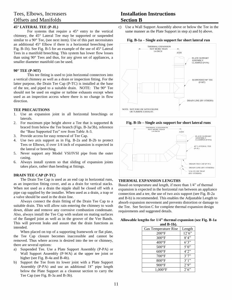
c) Use a Wall Support Assembly above or below the Tee in the
same manner as the Plate Support in step a) and b) above.
Fig. B-1a – Single axis support for short lateral run
NOT MORE THAN1/4 INCH
THERMAL EXPANSION
DRAIN LINE (BY OTHERS)
OR TURBINE EXHAUST.NOT FOR USE WITH ENGINENOTE:
AXIS
(P-MT)SUSPENDED 90° TEE
CLAMPED (P-PA)ASSEMBLYPLATE SUPPORT
Fig. B-1b – Single axis support for short lateral runs
1/4 INCHNOT MORE THAN
THERMAL EXPANSION
DRAIN LINE (BY OTHERS)
DRAIN TEE CAP (P-TC)
(BY OTHERS)
VALVE OR TRAP
(P-JL)
45° LATERAL TEE
AXIS
CLAMPED (P-PA)ASSEMBLYPLATE SUPPORT
THERMAL EXPANSION LENGTHS
Based on temperature and length, if more than 1/4” of thermal
expansion is expected in the horizontal run between an appliance
connection and a tee, the use of two axis support (see Fig. B-2a
and B-b) is recommended. This enables the Adjustable Length to
absorb expansion movement and prevents distortion or damage to
the Tee. See Section C for complete thermal expansion design
requirements and suggested details.
Allowable lengths for 1/4” thermal expansion (see Fig. B-1a
and B-1b).
Gas Temperature Rise Length
200°F 12’6”
300°F 8’4”
400°F 6’3”
500°F 5’0”
600°F 4’2”
700°F 3’7”
800°F 3’1”
900°F 2’9”
1,000°F 2’6”
12
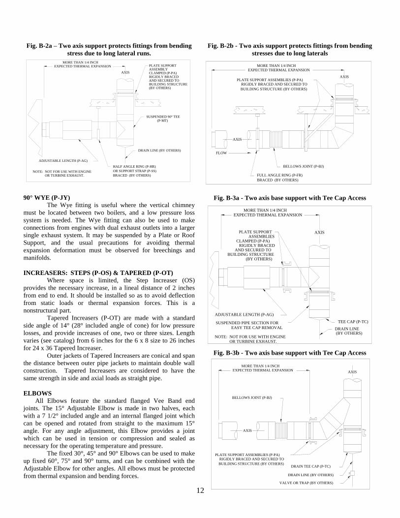
Fig. B-2a – Two axis support protects fittings from bending
stress due to long lateral runs.
EXPECTED THERMAL EXPANSIONMORE THAN 1/4 INCH
DRAIN LINE (BY OTHERS)
ADJUSTABLE LENGTH (P-AG)
BRACED (BY OTHERS)
OR SUPPORT STRAP (P-SS)
HALF ANGLE RING (P-HR)
(BY OTHERS)BUILDING STRUCTUREAND SECURED TORIGIDLY BRACED
OR TURBINE EXHAUST.NOT FOR USE WITH ENGINENOTE:
AXIS
(P-MT)SUSPENDED 90° TEE
CLAMPED (P-PA)ASSEMBLYPLATE SUPPORT
90° WYE (P-JY)
The Wye fitting is useful where the vertical chimney
must be located between two boilers, and a low pressure loss
system is needed. The Wye fitting can also be used to make
connections from engines with dual exhaust outlets into a larger
single exhaust system. It may be suspended by a Plate or Roof
Support, and the usual precautions for avoiding thermal
expansion deformation must be observed for breechings and
manifolds.
INCREASERS: STEPS (P-OS) & TAPERED (P-OT)
Where space is limited, the Step Increaser (OS)
provides the necessary increase, in a lineal distance of 2 inches
from end to end. It should be installed so as to avoid deflection
from static loads or thermal expansion forces. This is a
nonstructural part.
Tapered Increasers (P-OT) are made with a standard
side angle of 14° (28° included angle of cone) for low pressure
losses, and provide increases of one, two or three sizes. Length
varies (see catalog) from 6 inches for the 6 x 8 size to 26 inches
for 24 x 36 Tapered Increaser.
Outer jackets of Tapered Increasers are conical and span
the distance between outer pipe jackets to maintain double wall
construction. Tapered Increasers are considered to have the
same strength in side and axial loads as straight pipe.
ELBOWS
All Elbows feature the standard flanged Vee Band end
joints. The 15° Adjustable Elbow is made in two halves, each
with a 7 1/2° included angle and an internal flanged joint which
can be opened and rotated from straight to the maximum 15°
angle. For any angle adjustment, this Elbow provides a joint
which can be used in tension or compression and sealed as
necessary for the operating temperature and pressure.
The fixed 30°, 45° and 90° Elbows can be used to make
up fixed 60°, 75° and 90° turns, and can be combined with the
Adjustable Elbow for other angles. All elbows must be protected
from thermal expansion and bending forces.
Fig. B-2b - Two axis support protects fittings from bending
stresses due to long laterals
AXIS
EXPECTED THERMAL EXPANSIONMORE THAN 1/4 INCH
BUILDING STRUCTURE (BY OTHERS)
RIGIDLY BRACED AND SECURED TOPLATE SUPPORT ASSEMBLIES (P-PA)
BRACED (BY OTHERS)
FULL ANGLE RING (P-FR)
BELLOWS JOINT (P-BJ)
FLOW
AXIS
Fig. B-3a - Two axis base support with Tee Cap Access
EXPECTED THERMAL EXPANSIONMORE THAN 1/4 INCH
DRAIN LINE
ADJUSTABLE LENGTH (P-AG)
EASY TEE CAP REMOVALSUSPENDED PIPE SECTION FOR TEE CAP (P-TC)
(BY OTHERS)BUILDING STRUCTURE
AND SECURED TORIGIDLY BRACED
OR TURBINE EXHAUST.NOT FOR USE WITH ENGINENOTE:
AXIS
CLAMPED (P-PA)ASSEMBLIES
PLATE SUPPORT
(BY OTHERS)
Fig. B-3b - Two axis base support with Tee Cap Access
DRAIN LINE (BY OTHERS)
DRAIN TEE CAP (P-TC)
VALVE OR TRAP (BY OTHERS)
BELLOWS JOINT (P-BJ)
EXPECTED THERMAL EXPANSIONMORE THAN 1/4 INCH
BUILDING STRUCTURE (BY OTHERS)
RIGIDLY BRACED AND SECURED TOPLATE SUPPORT ASSEMBLIES (P-PA)
AXIS
AXIS
13
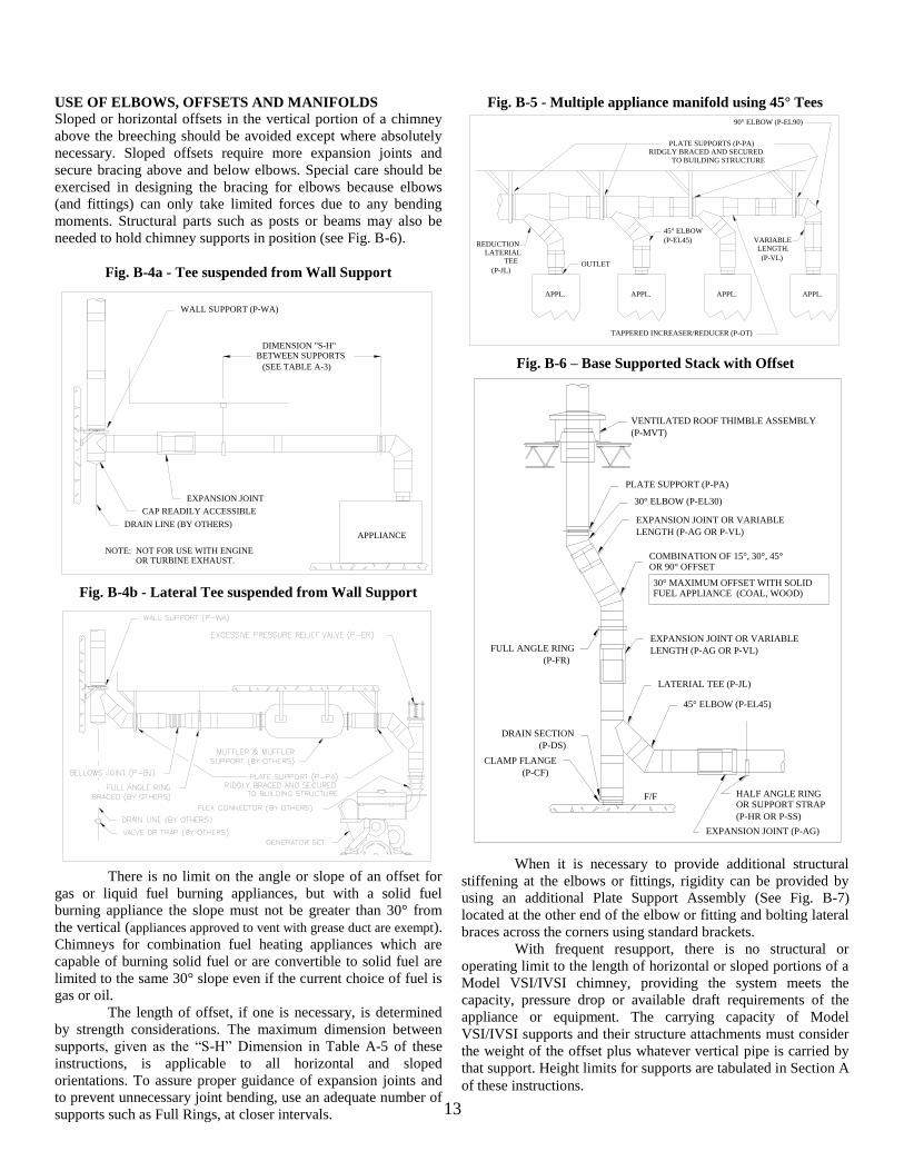
USE OF ELBOWS, OFFSETS AND MANIFOLDS
Sloped or horizontal offsets in the vertical portion of a chimney
above the breeching should be avoided except where absolutely
necessary. Sloped offsets require more expansion joints and
secure bracing above and below elbows. Special care should be
exercised in designing the bracing for elbows because elbows
(and fittings) can only take limited forces due to any bending
moments. Structural parts such as posts or beams may also be
needed to hold chimney supports in position (see Fig. B-6).
Fig. B-4a - Tee suspended from Wall Support
WALL SUPPORT (P-WA)
EXPANSION JOINT
CAP READILY ACCESSIBLE
(SEE TABLE A-3)
BETWEEN SUPPORTSDIMENSION "S-H"
DRAIN LINE (BY OTHERS)
APPLIANCE
NOTE: NOT FOR USE WITH ENGINEOR TURBINE EXHAUST.
Fig. B-4b - Lateral Tee suspended from Wall Support
There is no limit on the angle or slope of an offset for
gas or liquid fuel burning appliances, but with a solid fuel
burning appliance the slope must not be greater than 30° from
the vertical (appliances approved to vent with grease duct are exempt).
Chimneys for combination fuel heating appliances which are
capable of burning solid fuel or are convertible to solid fuel are
limited to the same 30° slope even if the current choice of fuel is
gas or oil.
The length of offset, if one is necessary, is determined
by strength considerations. The maximum dimension between
supports, given as the “S-H” Dimension in Table A-5 of these
instructions, is applicable to all horizontal and sloped
orientations. To assure proper guidance of expansion joints and
to prevent unnecessary joint bending, use an adequate number of
supports such as Full Rings, at closer intervals.
Fig. B-5 - Multiple appliance manifold using 45° Tees
(P-EL45)
45° ELBOW
OUTLET(P-VL)
LENGTH.VARIABLE
TO BUILDING STRUCTURERIDGLY BRACED AND SECURED
PLATE SUPPORTS (P-PA)
(P-JL)
TEELATERIAL
REDUCTION
TAPPERED INCREASER/REDUCER (P-OT)
90° ELBOW (P-EL90)
APPL.APPL.APPL. APPL.
Fig. B-6 – Base Supported Stack with Offset
(P-CF)
CLAMP FLANGE
(P-HR OR P-SS)
OR SUPPORT STRAPHALF ANGLE RING
EXPANSION JOINT (P-AG)
45° ELBOW (P-EL45)
LATERIAL TEE (P-JL)
LENGTH (P-AG OR P-VL)
EXPANSION JOINT OR VARIABLE
OR 90° OFFSETCOMBINATION OF 15°, 30°, 45°
LENGTH (P-AG OR P-VL)
EXPANSION JOINT OR VARIABLE
30° ELBOW (P-EL30)
(P-MVT)
VENTILATED ROOF THIMBLE ASSEMBLY
(P-DS)
DRAIN SECTION
(P-FR)
FULL ANGLE RING
PLATE SUPPORT (P-PA)
FUEL APPLIANCE (COAL, WOOD)30° MAXIMUM OFFSET WITH SOLID
F/F
When it is necessary to provide additional structural
stiffening at the elbows or fittings, rigidity can be provided by
using an additional Plate Support Assembly (See Fig. B-7)
located at the other end of the elbow or fitting and bolting lateral
braces across the corners using standard brackets.
With frequent resupport, there is no structural or
operating limit to the length of horizontal or sloped portions of a
Model VSI/IVSI chimney, providing the system meets the
capacity, pressure drop or available draft requirements of the
appliance or equipment. The carrying capacity of Model
VSI/IVSI supports and their structure attachments must consider
the weight of the offset plus whatever vertical pipe is carried by
that support. Height limits for supports are tabulated in Section A
of these instructions.
14
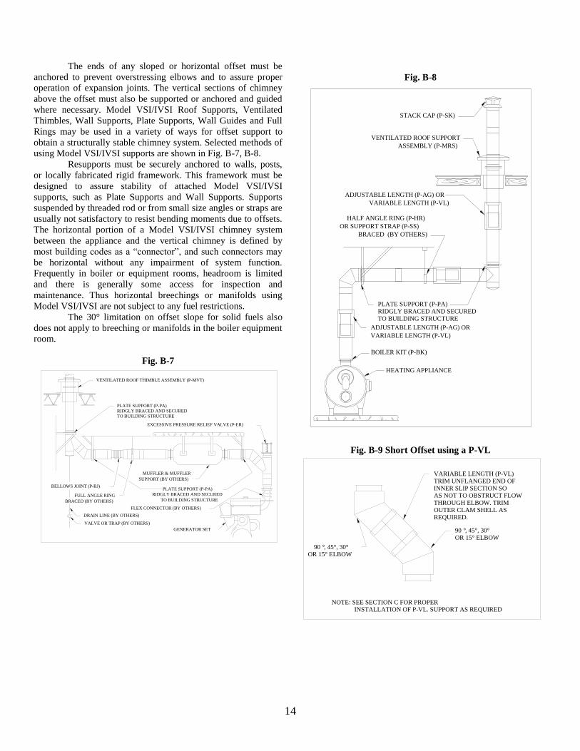
The ends of any sloped or horizontal offset must be
anchored to prevent overstressing elbows and to assure proper
operation of expansion joints. The vertical sections of chimney
above the offset must also be supported or anchored and guided
where necessary. Model VSI/IVSI Roof Supports, Ventilated
Thimbles, Wall Supports, Plate Supports, Wall Guides and Full
Rings may be used in a variety of ways for offset support to
obtain a structurally stable chimney system. Selected methods of
using Model VSI/IVSI supports are shown in Fig. B-7, B-8.
Resupports must be securely anchored to walls, posts,
or locally fabricated rigid framework. This framework must be
designed to assure stability of attached Model VSI/IVSI
supports, such as Plate Supports and Wall Supports. Supports
suspended by threaded rod or from small size angles or straps are
usually not satisfactory to resist bending moments due to offsets.
The horizontal portion of a Model VSI/IVSI chimney system
between the appliance and the vertical chimney is defined by
most building codes as a “connector”, and such connectors may
be horizontal without any impairment of system function.
Frequently in boiler or equipment rooms, headroom is limited
and there is generally some access for inspection and
maintenance. Thus horizontal breechings or manifolds using
Model VSI/IVSI are not subject to any fuel restrictions.
The 30° limitation on offset slope for solid fuels also
does not apply to breeching or manifolds in the boiler equipment
room.
Fig. B-7
GENERATOR SET
FLEX CONNECTOR (BY OTHERS)
SUPPORT (BY OTHERS)
MUFFLER & MUFFLER
EXCESSIVE PRESSURE RELIEF VALVE (P-ER)
BRACED (BY OTHERS)
FULL ANGLE RING
BELLOWS JOINT (P-BJ)
DRAIN LINE (BY OTHERS)
VALVE OR TRAP (BY OTHERS)
VENTILATED ROOF THIMBLE ASSEMBLY (P-MVT)
PLATE SUPPORT (P-PA)
RIDGLY BRACED AND SECURED
TO BUILDING STRUCTURE
TO BUILDING STRUCTURERIDGLY BRACED AND SECUREDPLATE SUPPORT (P-PA)
Fig. B-8
HEATING APPLIANCE
BOILER KIT (P-BK)
VARIABLE LENGTH (P-VL)
ADJUSTABLE LENGTH (P-AG) OR
BRACED (BY OTHERS)
OR SUPPORT STRAP (P-SS)
HALF ANGLE RING (P-HR)
VARIABLE LENGTH (P-VL)
ADJUSTABLE LENGTH (P-AG) OR
ASSEMBLY (P-MRS)
VENTILATED ROOF SUPPORT
STACK CAP (P-SK)
PLATE SUPPORT (P-PA)RIDGLY BRACED AND SECUREDTO BUILDING STRUCTURE
Fig. B-9 Short Offset using a P-VL
OR 15° ELBOW, 45°, 30°°90
REQUIRED.OUTER CLAM SHELL ASTHROUGH ELBOW. TRIMAS NOT TO OBSTRUCT FLOWINNER SLIP SECTION SOTRIM UNFLANGED END OFVARIABLE LENGTH (P-VL)
OR 15° ELBOW, 45°, 30°°90
INSTALLATION OF P-VL. SUPPORT AS REQUIREDNOTE: SEE SECTION C FOR PROPER
15
THERMAL EXPANSION THERMAL EXPANSION
The inner pipe of Model VSI/IVSI is load bearing and
its thermal expansion is the same as that of a continuous pipe. A
simplified rule for exhaust pipe expansion estimation is that the
axial growth will be approx. 1” per 100’ of pipe length for each
100°F the flue gas temperature is above the surrounding air
temperature.
When assembled in any orientation, the amount of
thermal expansion of the inner pipe is directly dependent on the
inner wall temperature and the length of pipe between fixed
points. Good installation practice requires that expansion greater
than 1/4 inch will be compensated for using a Bellows Joint or
Adjustable Length, depending on the maximum pressure
encountered.
The flanged inner piping joints have negligible flexing
capacity, and in addition, tees and elbows are not designed to
withstand bending moment forces. Because the amount of outer
casing axial movement is the same as inner casing movement,
the outer jackets of piping must slide to avoid excessive forces
on tees, elbows or fixed points. To accommodate outer casing
movements, external guides along walls at floors, or in lateral
breechings, must allow for movement of pipe.
NOTE: When resupporting a high rise exhaust system,
Adjustable Lengths (AG) or Bellows Joints (BJ) must
be used just below every support above the first to
compensate for thermal expansion. For engine and
turbine exhaust systems requiring pressures to 60 inches
of water column, or where the construction must be
absolutely gas tight, all welded Bellows Joints (BJ) are
recommended for expansion and vibrational movements
of the exhaust piping. Out-of-doors construction or low
pressure systems, such as boilers (to 6 inches of water
column), can effectively use the Adjustable Length
(AG).
Spacing of guides and supports, when a thermal expansion part is
used, should be not greater than specified in Section A. Proper
guiding and support of expansion parts often requires closer
spacing.
BELLOWS JOINTS: LINED (BJ)
For exhaust pressure to 60 inches of water column,
Bellows Joints are recommended for expansion and vibrational
movements of the piping. See Fig. C-2 for an illustration of a
Bellows Joint (BJ).
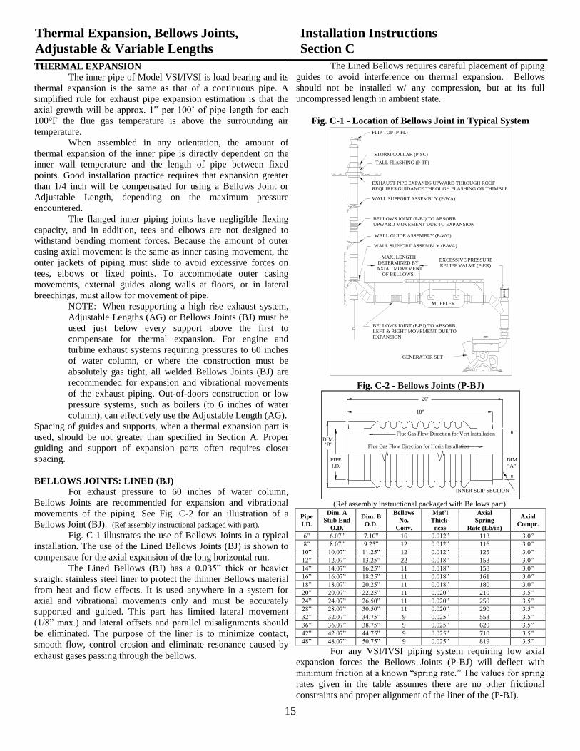
Fig. C-1 illustrates the use of Bellows Joints in a typical
installation. The use of the Lined Bellows Joints (BJ) is shown to
compensate for the axial expansion of the long horizontal run.
The Lined Bellows (BJ) has a 0.035” thick or heavier
straight stainless steel liner to protect the thinner Bellows
material from heat and flow effects. It is used anywhere in a
system for axial and vibrational movements only and must be
accurately supported and guided. This part has limited lateral
movement (1/8” max.) and lateral offsets and parallel
misalignments should be eliminated. The purpose of the liner is
to minimize contact, smooth flow, control erosion and eliminate
resonance caused by exhaust gases passing through the bellows.
The Lined Bellows requires careful placement of piping
The Lined Bellows requires careful placement of piping
guides to avoid interference on thermal expansion. Bellows
should not be installed w/ any compression, but at its full
uncompressed length in ambient state.
Fig. C-1 - Location of Bellows Joint in Typical System
UPWARD MOVEMENT DUE TO EXPANSIONBELLOWS JOINT (P-BJ) TO ABSORB
WALL GUIDE ASSEMBLY (P-WG)
WALL SUPPORT ASSEMBLY (P-WA)
WALL SUPPORT ASSEMBLY (P-WA)
EXPANSIONLEFT & RIGHT MOVEMENT DUE TOBELLOWS JOINT (P-BJ) TO ABSORB
GENERATOR SET
REQUIRES GUIDANCE THROUGH FLASHING OR THIMBLEEXHAUST PIPE EXPANDS UPWARD THROUGH ROOF
TALL FLASHING (P-TF)
STORM COLLAR (P-SC)
FLIP TOP (P-FL)
RELIEF VALVE (P-ER)EXCESSIVE PRESSURE
OF BELLOWSAXIAL MOVEMENTDETERMINED BY
MAX. LENGTH
MUFFLER
Fig. C-2 - Bellows Joints (P-BJ)
INNER SLIP SECTION
Flue Gas Flow Direction for Vert Installation
Flue Gas Flow Direction for Horiz Installation
PIPE
DIM.
18"
20"
I.D.
"B"
"A"
DIM
(Ref assembly instructional packaged with Bellows part).
Pipe
I.D.
Dim. A
Stub End
O.D.
Dim. B
O.D.
Bellows
No.
Conv.
Mat’l
Thick-
ness
Axial
Spring
Rate (Lb/in)
Axial
Compr.
6” 6.07” 7.10” 16 0.012” 113 3.0”
8” 8.07” 9.25” 12 0.012” 116 3.0”
10” 10.07” 11.25” 12 0.012” 125 3.0”
12” 12.07” 13.25” 22 0.018” 153 3.0”
14” 14.07” 16.25” 11 0.018” 158 3.0”
16” 16.07” 18.25” 11 0.018” 161 3.0”
18” 18.07” 20.25” 11 0.018” 180 3.0”
20” 20.07” 22.25” 11 0.020” 210 3.5”
24” 24.07” 26.50” 11 0.020” 250 3.5”
28” 28.07” 30.50” 11 0.020” 290 3.5”
32” 32.07” 34.75” 9 0.025” 553 3.5”
36” 36.07” 38.75” 9 0.025” 620 3.5”
42” 42.07” 44.75” 9 0.025” 710 3.5”
48” 48.07” 50.75” 9 0.025” 819 3.5”
For any VSI/IVSI piping system requiring low axial
expansion forces the Bellows Joints (P-BJ) will deflect with
minimum friction at a known “spring rate.” The values for spring
rates given in the table assumes there are no other frictional
constraints and proper alignment of the liner of the (P-BJ).
Thermal Expansion, Bellows Joints,
Adjustable & Variable Lengths
Installation Instructions
Section C
THERMAL EXPANSION
The inner pipe of Model VSI/IVSI is load bearing and its
thermal expansion is the same as that of a continuous pipe. A
simplified rule for exhaust pipe expansion estimation is that the
axial growth will be approx. 1” per 100’ of pipe length for each
100°F the flue gas temperature is above the surrounding air
temperature.
When assembled in any orientation, the amount of
thermal expansion of the inner pipe is directly dependent on the
inner wall temperature and the length of pipe between fixed
points. Good installation practice requires that expansion greater
than 1/4 inch will be compensated for using a Bellows Joint or
Adjustable Length, depending on the maximum pressure
encountered.
The flanged inner piping joints have negligible flexing
capacity, and in addition, tees and elbows are not designed to
withstand bending moment forces. Because the amount of outer
casing axial movement is the same as inner casing movement, the
outer jackets of piping must slide to avoid excessive forces on
tees, elbows or fixed points. To accommodate outer casing
movements, external guides along walls at floors, or in lateral
breechings, must allow for movement of pipe.
NOTE: When resupporting a high rise exhaust system,
Adjustable Lengths (AG) or Bellows Joints (BJ) must be
used just below every support above the first to
compensate for thermal expansion. For engine and
turbine exhaust systems requiring pressures to 60 inches
of water column, or where the construction must be
absolutely gas tight, all welded Bellows Joints (BJ) are
recommended for expansion and vibrational movements
of the exhaust piping. Out-of-doors construction or low
pressure systems, such as boilers (to 6 inches of water
column), can effectively use the Adjustable Length (AG).
Spacing of guides and supports, when a thermal expansion part is
used, should be not greater than specified in Section A. Proper
guiding and support of expansion parts often requires closer
spacing.
BELLOWS JOINTS: LINED (BJ)
For exhaust pressure to 60 inches of water column,
Bellows Joints are recommended for expansion and vibrational
movements of the piping. See Fig. C-2 for an illustration of a
Bellows Joint (BJ). (Ref assembly instructional packaged with part).
Fig. C-1 illustrates the use of Bellows Joints in a typical
installation. The use of the Lined Bellows Joints (BJ) is shown to
compensate for the axial expansion of the long horizontal run.
The Lined Bellows (BJ) has a 0.035” thick or heavier
straight stainless steel liner to protect the thinner Bellows material
from heat and flow effects. It is used anywhere in a system for
axial and vibrational movements only and must be accurately
supported and guided. This part has limited lateral movement
(1/8” max.) and lateral offsets and parallel misalignments should
be eliminated. The purpose of the liner is to minimize contact,
smooth flow, control erosion and eliminate resonance caused by
exhaust gases passing through the bellows.
16
At an operating gas temperature of 1000°F (70°F,
ambient) the VSI inner pipe in a typical engine exhaust system
will be at a temperature rise of approximately 750°F. The same
1,000°F gas temperature will create higher inner pipe
temperatures for model IVSI because it is better insulated.
Allowable expansion movements for Bellows Joints BJ
are given in Figure C-2. For the following Bellows sizes,
estimated cycle life is 6” - 12” = 4000 and 16” - 36” = 30,000 at
750°F.
The system operating pressure of 60 inches water
column (2.08 psi) is based on the estimated capability of ceramic
sealed Vee Band joints. The actual pressure limit of the welded
bellows will be 10 psi for 6” to 12” diameter and 5 psi for 16” to
48” diameter at 750°F.
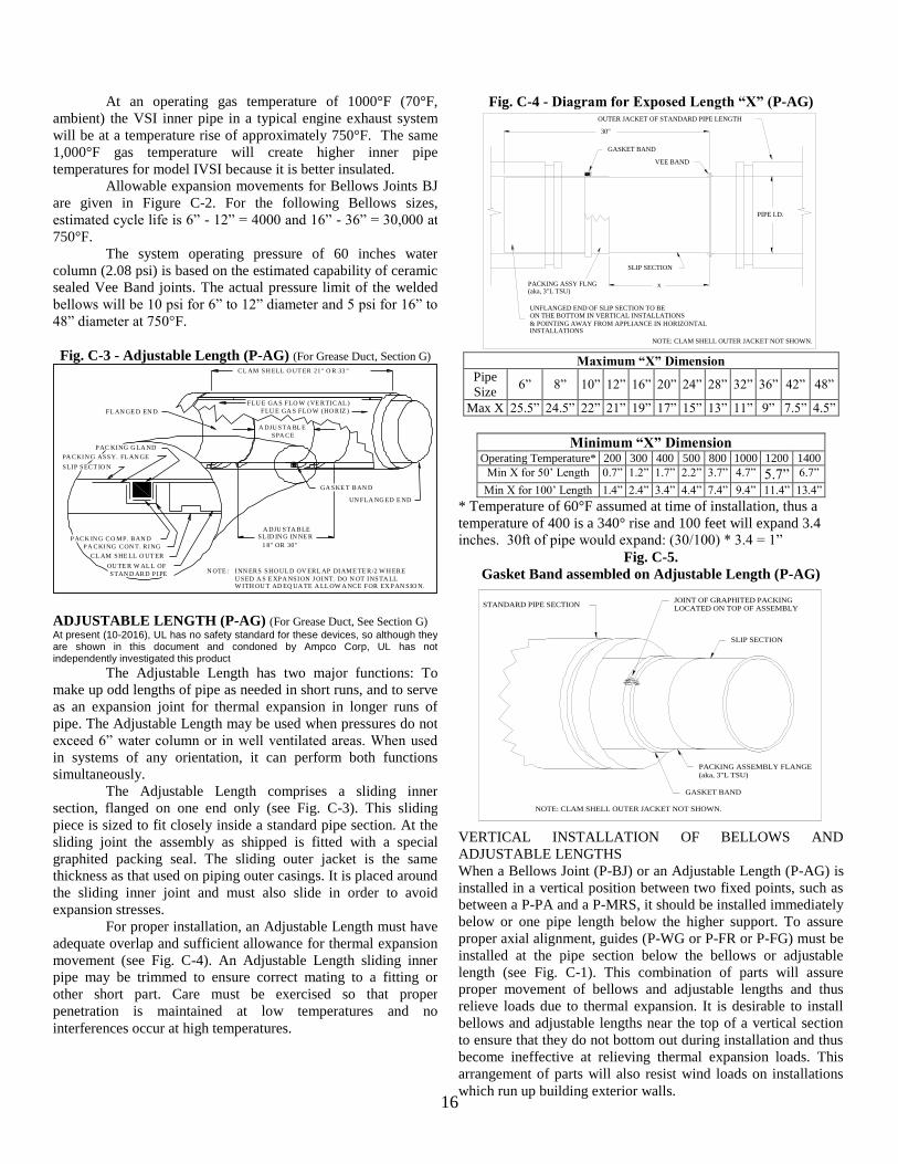
Fig. C-3 - Adjustable Length (P-AG) (For Grease Duct, Section G) CL AM SH ELL O UT ER 21" O R 33 "
FLU E GA S FLO W (VE RTICAL )
FLU E GA S FLO W (HO RIZ )
1 8" OR 30"
SL ID IN G IN NE RA DJU STA BLE
STAN D ARD PIPE
OU TE R W AL L OF
CL AM SHE LL O UT ER
PA CKING CON T. RING
PACK IN G CO MP. BAN D
SLIP SECT IO N
PA CKIN G ASSY. FL AN GE
PAC KING G LA ND
GA SKE T BAN D
FL AN GE D EN D
UN FLA NG ED E ND
W ITH OU T AD EQ UA TE A LL OW A NCE FOR EX PAN SIO N.U SED A S E XPA NSION J OINT. DO N OT INSTA LL
INN ERS SHO UL D OV ERL AP DIAME TE R/2 W H EREN OTE :
SPA CE
A DJU STA BL E
ADJUSTABLE LENGTH (P-AG) (For Grease Duct, See Section G) At present (10-2016), UL has no safety standard for these devices, so although they are shown in this document and condoned by Ampco Corp, UL has not independently investigated this product
The Adjustable Length has two major functions: To
make up odd lengths of pipe as needed in short runs, and to serve
as an expansion joint for thermal expansion in longer runs of
pipe. The Adjustable Length may be used when pressures do not
exceed 6” water column or in well ventilated areas. When used
in systems of any orientation, it can perform both functions
simultaneously.
The Adjustable Length comprises a sliding inner
section, flanged on one end only (see Fig. C-3). This sliding
piece is sized to fit closely inside a standard pipe section. At the
sliding joint the assembly as shipped is fitted with a special
graphited packing seal. The sliding outer jacket is the same
thickness as that used on piping outer casings. It is placed around
the sliding inner joint and must also slide in order to avoid
expansion stresses.
For proper installation, an Adjustable Length must have
adequate overlap and sufficient allowance for thermal expansion
movement (see Fig. C-4). An Adjustable Length sliding inner
pipe may be trimmed to ensure correct mating to a fitting or
other short part. Care must be exercised so that proper
penetration is maintained at low temperatures and no
interferences occur at high temperatures.
Fig. C-4 - Diagram for Exposed Length “X” (P-AG)
x
30"
GASKET BAND
VEE BAND
SLIP SECTION
UNFLANGED END OF SLIP SECTION TO BE
OUTER JACKET OF STANDARD PIPE LENGTH
PIPE I.D.
NOTE: CLAM SHELL OUTER JACKET NOT SHOWN.
ON THE BOTTOM IN VERTICAL INSTALLATIONS
& POINTING AWAY FROM APPLIANCE IN HORIZONTALINSTALLATIONS
PACKING ASSY FLNG(aka, 3"L TSU)
Maximum “X” Dimension
Pipe
Size 6” 8” 10” 12” 16” 20” 24” 28” 32” 36” 42” 48”
Max X 25.5” 24.5” 22” 21” 19” 17” 15” 13” 11” 9” 7.5” 4.5”
Minimum “X” Dimension Operating Temperature* 200 300 400 500 800 1000 1200 1400
Min X for 50’ Length 0.7” 1.2” 1.7” 2.2” 3.7” 4.7” 5.7” 6.7”
Min X for 100’ Length 1.4” 2.4” 3.4” 4.4” 7.4” 9.4” 11.4” 13.4”
* Temperature of 60°F assumed at time of installation, thus a
temperature of 400 is a 340° rise and 100 feet will expand 3.4
inches. 30ft of pipe would expand: (30/100) * 3.4 = 1”
Fig. C-5.
Gasket Band assembled on Adjustable Length (P-AG)
PACKING ASSEMBLY FLANGE
GASKET BAND
SLIP SECTION
STANDARD PIPE SECTIONLOCATED ON TOP OF ASSEMBLYJOINT OF GRAPHITED PACKING
NOTE: CLAM SHELL OUTER JACKET NOT SHOWN.
(aka, 3"L TSU)
VERTICAL INSTALLATION OF BELLOWS AND
ADJUSTABLE LENGTHS
When a Bellows Joint (P-BJ) or an Adjustable Length (P-AG) is
installed in a vertical position between two fixed points, such as
between a P-PA and a P-MRS, it should be installed immediately
below or one pipe length below the higher support. To assure
proper axial alignment, guides (P-WG or P-FR or P-FG) must be
installed at the pipe section below the bellows or adjustable
length (see Fig. C-1). This combination of parts will assure
proper movement of bellows and adjustable lengths and thus
relieve loads due to thermal expansion. It is desirable to install
bellows and adjustable lengths near the top of a vertical section
to ensure that they do not bottom out during installation and thus
become ineffective at relieving thermal expansion loads. This
arrangement of parts will also resist wind loads on installations
which run up building exterior walls.
17
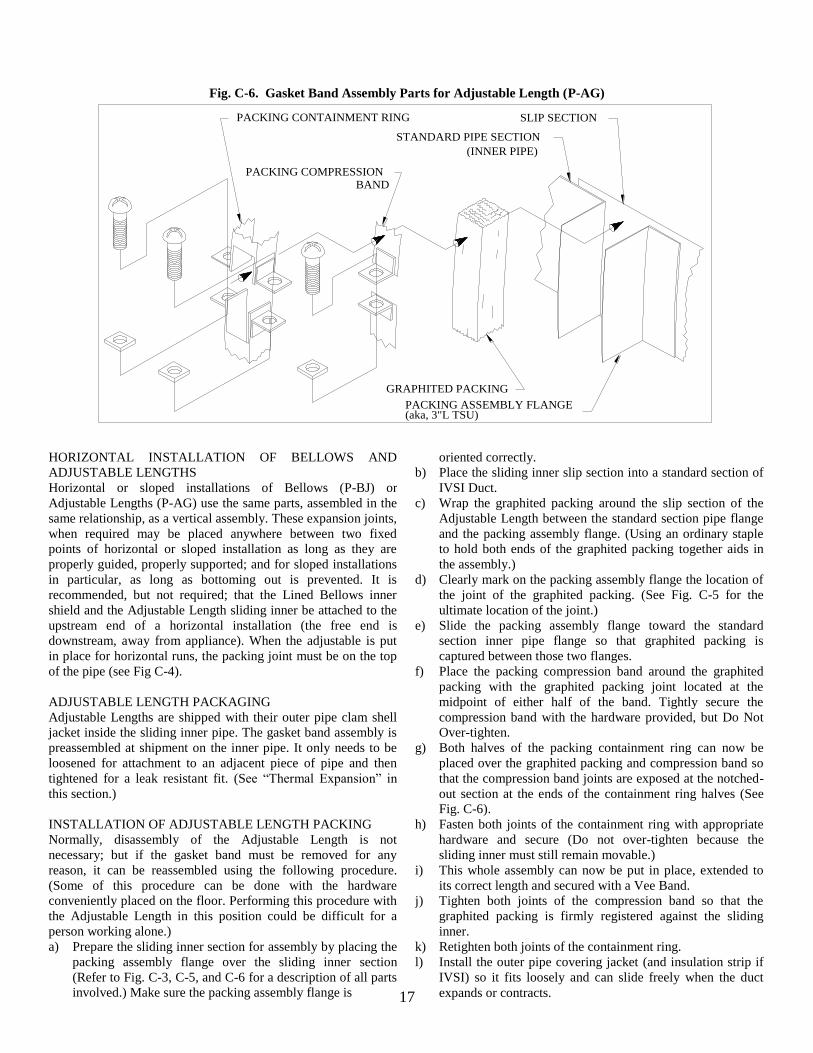
Fig. C-6. Gasket Band Assembly Parts for Adjustable Length (P-AG)
SLIP SECTION
(INNER PIPE)
STANDARD PIPE SECTION
BANDPACKING COMPRESSION
PACKING CONTAINMENT RING
GRAPHITED PACKING
PACKING ASSEMBLY FLANGE(aka, 3"L TSU)
HORIZONTAL INSTALLATION OF BELLOWS AND
ADJUSTABLE LENGTHS
Horizontal or sloped installations of Bellows (P-BJ) or
Adjustable Lengths (P-AG) use the same parts, assembled in the
same relationship, as a vertical assembly. These expansion joints,
when required may be placed anywhere between two fixed
points of horizontal or sloped installation as long as they are
properly guided, properly supported; and for sloped installations
in particular, as long as bottoming out is prevented. It is
recommended, but not required; that the Lined Bellows inner
shield and the Adjustable Length sliding inner be attached to the
upstream end of a horizontal installation (the free end is
downstream, away from appliance). When the adjustable is put
in place for horizontal runs, the packing joint must be on the top
of the pipe (see Fig C-4).
ADJUSTABLE LENGTH PACKAGING
Adjustable Lengths are shipped with their outer pipe clam shell
jacket inside the sliding inner pipe. The gasket band assembly is
preassembled at shipment on the inner pipe. It only needs to be
loosened for attachment to an adjacent piece of pipe and then
tightened for a leak resistant fit. (See “Thermal Expansion” in
this section.)
INSTALLATION OF ADJUSTABLE LENGTH PACKING
Normally, disassembly of the Adjustable Length is not
necessary; but if the gasket band must be removed for any
reason, it can be reassembled using the following procedure.
(Some of this procedure can be done with the hardware
conveniently placed on the floor. Performing this procedure with
the Adjustable Length in this position could be difficult for a
person working alone.)
a) Prepare the sliding inner section for assembly by placing the
packing assembly flange over the sliding inner section
(Refer to Fig. C-3, C-5, and C-6 for a description of all parts
involved.) Make sure the packing assembly flange is
oriented correctly.
b) Place the sliding inner slip section into a standard section of
IVSI Duct.
c) Wrap the graphited packing around the slip section of the
Adjustable Length between the standard section pipe flange
and the packing assembly flange. (Using an ordinary staple
to hold both ends of the graphited packing together aids in
the assembly.)
d) Clearly mark on the packing assembly flange the location of
the joint of the graphited packing. (See Fig. C-5 for the
ultimate location of the joint.)
e) Slide the packing assembly flange toward the standard
section inner pipe flange so that graphited packing is
captured between those two flanges.
f) Place the packing compression band around the graphited
packing with the graphited packing joint located at the
midpoint of either half of the band. Tightly secure the
compression band with the hardware provided, but Do Not
Over-tighten.
g) Both halves of the packing containment ring can now be
placed over the graphited packing and compression band so
that the compression band joints are exposed at the notched-
out section at the ends of the containment ring halves (See
Fig. C-6).
h) Fasten both joints of the containment ring with appropriate
hardware and secure (Do not over-tighten because the
sliding inner must still remain movable.)
i) This whole assembly can now be put in place, extended to
its correct length and secured with a Vee Band.
j) Tighten both joints of the compression band so that the
graphited packing is firmly registered against the sliding
inner.
k) Retighten both joints of the containment ring.
l) Install the outer pipe covering jacket (and insulation strip if
IVSI) so it fits loosely and can slide freely when the duct
expands or contracts.
18
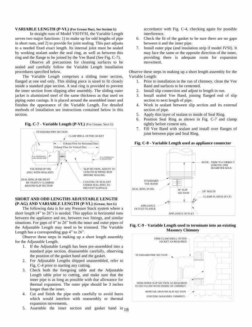
VARIABLE LENGTH (P-VL) (For Grease Duct, See Section G)
In straight runs of Model VSI/IVSI, the Variable Length
serves two major functions: 1) to make up for odd lengths of pipe
in short runs, and 2) to provide for joint sealing. This part adjusts
to a needed fixed exact length. Its internal joint must be sealed
by working sealant under the seal ring, as well as between this
ring and the flange to be joined by the Vee Band (See Fig. C-7).
Observe all precautions for cleaning surfaces to be
sealed and carefully follow the Variable Length installation
procedures specified below.
The Variable Length comprises a sliding inner section,
flanged at one end only. This sliding piece is sized to fit closely
inside a standard pipe section. A seal ring is provided to prevent
the inner section from slipping after assembly. The sliding outer
jacket is aluminized steel of the same thickness as that used on
piping outer casings. It is placed around the assembled inner and
finishes the appearance of the Variable Length. For detailed
methods of installation see instructions contained below in this
section.
Fig. C-7 - Variable Length (P-VL) (For Grease, Sect G)
VEE BAND (P-VB)
(FILL WITH SEALANT)
SEAL RING (P-SR) MUSTBE TIGHTLY CLAMPED
AROUND SLIP SECTION
SLIP SECTION. ADJUST TOLENGTH IN PIPING RUNBEFORE SEALING
COATING OF SEALANTUNDER SEAL RING TOPREVENT SLIPPAGE
STANDARD PIPE SECTION
CLAM SHELL OUTER JACKET
UNFLANGED ENDP-VL INNERWALL
FLANGED ENDP-VL INNERWALL
Exhaust Flow for Horizontal Duct
Exhaust Flow for Vertical Duct
SHORT AND ODD LENGTHS ADJUSTABLE LENGTH
(P-AG) AND VARIABLE LENGTH (P-VL) (Grease, Sect G)
The following data is for any Pressure Stack system where a
short length (4” to 26”) is needed. This applies in horizontal runs
between the appliance and tee, between two fittings, and similar
situations. For gaps of 4” to 26” both the inner and outer pipes of
the Adjustable Length may need to be trimmed. The Variable
Length has a corresponding gap 4” to 26”.
Observe these steps in making up a short length assembly
for the Adjustable Length.
1. If the Adjustable Length has been pre-assembled into a
standard pipe section, disassemble carefully, observing
the position of the gasket band and the gasket.
2. For Adjustable Lengths shipped unassembled, refer to
Fig. C-4 prior to starting any cutting.
3. Check both the foregoing table and the Adjustable
Length table prior to cutting, and make sure that the
inner pipe is as long as possible with due allowance for
thermal expansion. The outer pipe should be 3 inches
longer than the inner.
4. Cut and finish the pipe ends carefully to avoid burrs
which would interfere with reassembly or thermal
expansion movements.
5. Assemble the inner section and gasket band in
accordance with Fig. C-4, checking again for possible
interference.
6. Check the fit of the gasket to be sure there are no gaps
between it and the inner pipe.
7. Install outer pipe (and insulation strip if model IVSI). It
may face the same or the opposite direction of the inner,
providing there is adequate room for expansion
movement.
Observe these steps in making up a short length assembly for the
Variable Length:
1. Prior to installation in the run of chimney, clean the Vee
Band and surfaces to be cemented.
2. Install slip connection and adjust to length in run.
3. Install sealed Vee Band, joining flanged end of slip
section to next length of pipe.
4. Work in sealant between slip section and its external
section of pipe.
5. Apply thin layer of sealant to inside of Seal Ring.
6. Position Seal Ring as shown in Fig. C-7 and clamp
tightly before cement sets.
7. Fill Vee Band with sealant and install over flanges of
joint between pipe and Seal Ring.
Fig. C-8 - Variable Length used as appliance connector
SECTION
30" SLIP
DIAMETER MAX.LENGTH. ONETRIM TO CORRECTNOTE:
STANDARDVEE BAND
SEAL RING (P-SR)
APPLIANCEOUTLET FLANGE
CLAMP FLANGE (P-CF)
3/8" BOLTS
APPLIANCE OUTLET
Fig. C-9 - Variable Length used to terminate into an existing
Masonry Chimney
TO SET FLUSH WITH INSIDE OF CHIMNEY.TRIM INNER SLIP SECTION AS REQUIRED
EXISTING MASONRY CHIMNEY
MORTAR AROUND SLIP SECTION
STANDARD PIPE SECTION
TRIM CLAM SHELL OUTERJACKET AS REQUIRED
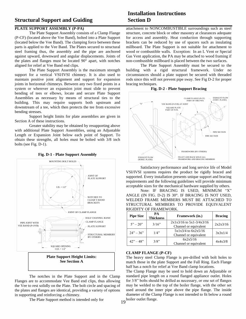
19
PLATE SUPPORT ASSEMBLY (P-PA)
The Plate Support Assembly consists of a Clamp Flange
(P-CF) (located above the Vee Band), bolted into a Plate Support
(located below the Vee Band). The clamping force between these
parts is applied to the Vee Band. The Plates secured to structural
steel framing thus, the assembly and the pipe are anchored
against upward, downward and angular displacements. Joints of
the plates and flanges must be located 90° apart, with notches
aligned for relief at Vee Band end clips.
The Plate Support Assembly is the maximum strength
support for a vertical VSI/IVSI chimney. It is also used to
maintain positive joint alignment and support for expansion
joints in horizontal chimneys. Between any two fixed points in a
system or wherever an expansion joint must slide to prevent
bending of tees or elbows, locate and secure Plate Support
Assemblies as necessary by means of structural ties to the
building. This may require supports both upstream and
downstream of a tee, which then protects the tee from excessive
bending stresses.
Support height limits for plate assemblies are given in
Section A of these instructions.
Greater stability may be obtained by resupporting above
with additional Plate Support Assemblies, using an Adjustable
Length or Expansion Joint below each point of Support. To
obtain these strengths, all holes must be bolted with 3/8 inch
bolts (see Fig. D-1).
Fig. D-1 - Plate Support Assembly
PIPE JOINT WITH
BY OTHERSSTRUCTURAL MEMBERS
PLATE SUPPORT
CLAMP FLANGE
VEE BAND (P-OVB)
HALF CHANNEL BAND
SQUARE OPENING
JOINT OF CLAMP FLANGE
BRACKETS
CLEAR V-BAND
NOTCHES TO
PLATE SUPPORT
JOINT OF
MOUNTING BOLT HOLES
I.D. + 1/2"
O.D. + 1/2"
attachment to NONCOMBUSTIBLE surroundings such as steel
structure, concrete block or other masonry at clearances adequate
for access and assembly. Heat conduction through supporting
brackets can be reduced by use of spacers such as insulating
millboard. The Plate Support is not suitable for attachment to
wood or combustible walls. Exception: In an L Vent or Special
Gas Vent application, the PA may be attached to wood framing if
non-combustible millboard is placed between the two surfaces.
The Plate Support Assembly must be secured to the
building with a rigid structural framework. Under no
circumstances should a plate support be secured with threaded
rods since this will not prevent pipe sway. See Fig D-2 for proper
bracing techniques.
Fig. D-2 - Plate Support Bracing
"X"
PART OF P-PASQUARE PLATE
VEE BAND (P-OVB) AT JOINT
PART OF THE P-PACLAMP FLANGE (P-CF)
PIPE SECTION
PIPE SECTION
FRAMEWORK (BY OTHERS)
FRAMEWORK AND BRACING MEMBERSFILLET AND BACK WELD ALL
(VERT. PLANE)EXHAUST FLOW
(HORIZ. PLANE)EXHAUST FLOW
Satisfactory performance and long service life of Model
VSI/IVSI systems requires the product be rigidly braced and
supported. Every installation presents unique support and bracing
requirements and the following guidelines will provide minimum
acceptable sizes for the mechanical hardware supplied by others.
Note: IF BRACING IS USED, MINIMUM “X”
ANGLE (IN FIG. D-2) IS 30°. IF BRACING IS NOT USED,
WELDED FRAME MEMBERS MUST BE ATTACHED TO
STRUCTURAL MEMBERS TO PROVIDE EQUIVALENT
RIGIDITY OF FRAMEWORK.
Pipe Size PA
Thickness Framework (in.) Bracing
5” – 20” 3/16” 2x1x3/16 to 5x1-3/4x3/16
Channel or equivalent 2x2x3/16
24” – 36” 1/4” 5x1x3/4 to 6x2x5/16
Channel or equivalent 3x3x1/4
42” – 48” 3/8” 6x2x5/16
Channel or equivalent 4x4x3/8
CLAMP FLANGE (P-CF)
The heavy steel Clamp Flange is pre-drilled with bolt holes to
match those in the plate Support and the Full Ring. Each Flange
half has a notch for relief at Vee Band clamp locations.
The Clamp Flange may be used to hold down an Adjustable or
standard pipe length on a round flanged appliance outlet. Holes
for 3/8” bolts should be drilled as necessary, or one set of flanges
may be welded to the top of the boiler flange, with the other set
used around the inner pipe above the pipe flange. The inside
diameter of the Clamp Flange is not intended to fit below a round
boiler outlet flange.
Structural Support and Guiding
Installation Instructions
Section D
Plate Support Height Limits:
See Section A
The notches in the Plate Support and in the Clamp
Flanges are to accommodate Vee Band end clips, thus allowing
the Vee to rest solidly on the Plate. The bolt circle and spacing of
the plates and flanges are identical, providing a variety of options
in supporting and reinforcing a chimney.
The Plate Support method is intended only for
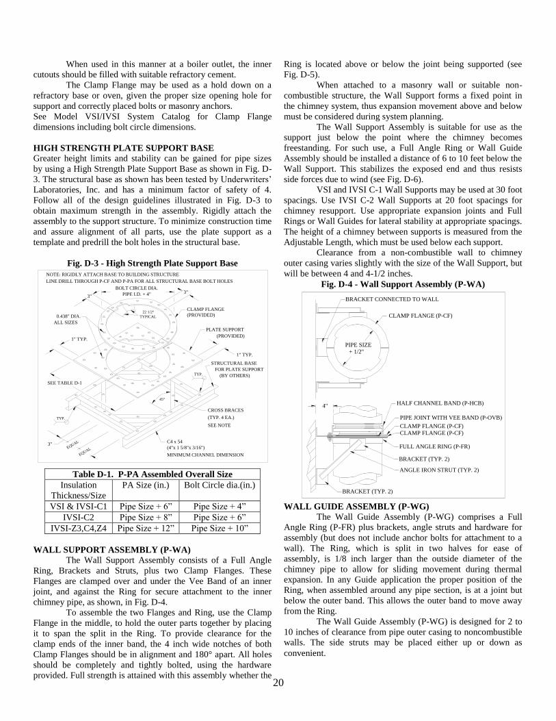
20
When used in this manner at a boiler outlet, the inner
cutouts should be filled with suitable refractory cement.
The Clamp Flange may be used as a hold down on a
refractory base or oven, given the proper size opening hole for
support and correctly placed bolts or masonry anchors.
See Model VSI/IVSI System Catalog for Clamp Flange
dimensions including bolt circle dimensions.
HIGH STRENGTH PLATE SUPPORT BASE
Greater height limits and stability can be gained for pipe sizes
by using a High Strength Plate Support Base as shown in Fig. D-
3. The structural base as shown has been tested by Underwriters’
Laboratories, Inc. and has a minimum factor of safety of 4.
Follow all of the design guidelines illustrated in Fig. D-3 to
obtain maximum strength in the assembly. Rigidly attach the
assembly to the support structure. To minimize construction time
and assure alignment of all parts, use the plate support as a
template and predrill the bolt holes in the structural base.
Fig. D-3 - High Strength Plate Support Base
EQUAL
(PROVIDED)
(PROVIDED)
(BY OTHERS)
LINE DRILL THROUGH P-CF AND P-PA FOR ALL STRUCTURAL BASE BOLT HOLES
NOTE: RIGIDLY ATTACH BASE TO BUILDING STRUCTURE
SEE TABLE D-1
(4"x 1 5/8"x 3/16")
C4 x 543"
EQUAL
TYP.
45°
SEE NOTE
(TYP. 4 EA.)
CROSS BRACES
TYP.
1" TYP.
1" TYP.
FOR PLATE SUPPORT
STRUCTURAL BASE
ALL SIZES
0.438" DIA.
PLATE SUPPORT
CLAMP FLANGE
3"3"
TYPICAL
22 1/2°
PIPE I.D. + 4"
BOLT CIRCLE DIA.
MINIMUM CHANNEL DIMENSION
Table D-1. P-PA Assembled Overall Size
Insulation
Thickness/Size
PA Size (in.) Bolt Circle dia.(in.)
VSI & IVSI-C1 Pipe Size + 6” Pipe Size + 4”
IVSI-C2 Pipe Size + 8” Pipe Size + 6”
IVSI-Z3,C4,Z4 Pipe Size + 12” Pipe Size + 10”
WALL SUPPORT ASSEMBLY (P-WA)
The Wall Support Assembly consists of a Full Angle
Ring, Brackets and Struts, plus two Clamp Flanges. These
Flanges are clamped over and under the Vee Band of an inner
joint, and against the Ring for secure attachment to the inner
chimney pipe, as shown, in Fig. D-4.
To assemble the two Flanges and Ring, use the Clamp
Flange in the middle, to hold the outer parts together by placing
it to span the split in the Ring. To provide clearance for the
clamp ends of the inner band, the 4 inch wide notches of both
Clamp Flanges should be in alignment and 180° apart. All holes
should be completely and tightly bolted, using the hardware
provided. Full strength is attained with this assembly whether the
Ring is located above or below the joint being supported (see
Fig. D-5).
When attached to a masonry wall or suitable non-
combustible structure, the Wall Support forms a fixed point in
the chimney system, thus expansion movement above and below
must be considered during system planning.
The Wall Support Assembly is suitable for use as the
support just below the point where the chimney becomes
freestanding. For such use, a Full Angle Ring or Wall Guide
Assembly should be installed a distance of 6 to 10 feet below the
Wall Support. This stabilizes the exposed end and thus resists
side forces due to wind (see Fig. D-6).
VSI and IVSI C-1 Wall Supports may be used at 30 foot
spacings. Use IVSI C-2 Wall Supports at 20 foot spacings for
chimney resupport. Use appropriate expansion joints and Full
Rings or Wall Guides for lateral stability at appropriate spacings.
The height of a chimney between supports is measured from the
Adjustable Length, which must be used below each support.
Clearance from a non-combustible wall to chimney
outer casing varies slightly with the size of the Wall Support, but
will be between 4 and 4-1/2 inches.
Fig. D-4 - Wall Support Assembly (P-WA)
BRACKET CONNECTED TO WALL
CLAMP FLANGE (P-CF)
CLAMP FLANGE (P-CF)
BRACKET (TYP. 2)
ANGLE IRON STRUT (TYP. 2)
BRACKET (TYP. 2)
FULL ANGLE RING (P-FR)
CLAMP FLANGE (P-CF)
PIPE JOINT WITH VEE BAND (P-OVB)
HALF CHANNEL BAND (P-HCB)4"
+ 1/2"
PIPE SIZE
WALL GUIDE ASSEMBLY (P-WG)
The Wall Guide Assembly (P-WG) comprises a Full
Angle Ring (P-FR) plus brackets, angle struts and hardware for
assembly (but does not include anchor bolts for attachment to a
wall). The Ring, which is split in two halves for ease of
assembly, is 1/8 inch larger than the outside diameter of the
chimney pipe to allow for sliding movement during thermal
expansion. In any Guide application the proper position of the
Ring, when assembled around any pipe section, is at a joint but
below the outer band. This allows the outer band to move away
from the Ring.
The Wall Guide Assembly (P-WG) is designed for 2 to
10 inches of clearance from pipe outer casing to noncombustible
walls. The side struts may be placed either up or down as
convenient.
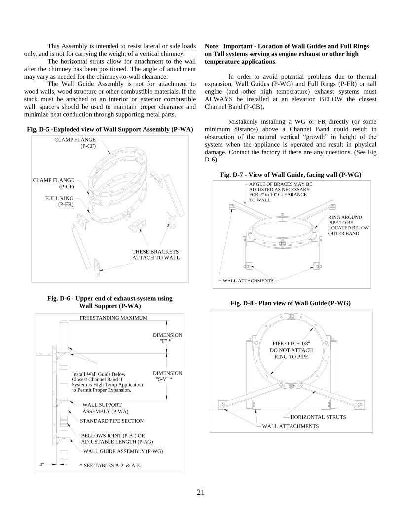
21
This Assembly is intended to resist lateral or side loads
only, and is not for carrying the weight of a vertical chimney.
The horizontal struts allow for attachment to the wall
after the chimney has been positioned. The angle of attachment
may vary as needed for the chimney-to-wall clearance.
The Wall Guide Assembly is not for attachment to
wood walls, wood structure or other combustible materials. If the
stack must be attached to an interior or exterior combustible
wall, spacers should be used to maintain proper clearance and
minimize heat conduction through supporting metal parts.
Fig. D-5 -Exploded view of Wall Support Assembly (P-WA)
CLAMP FLANGE
(P-CF)
(P-CF)
(P-FR)
CLAMP FLANGE
FULL RING
THESE BRACKETSATTACH TO WALL
Fig. D-6 - Upper end of exhaust system using
Wall Support (P-WA)
to Permit Proper Expansion.System is High Temp ApplicationClosest Channel Band if Install Wall Guide Below
ADJUSTABLE LENGTH (P-AG)
BELLOWS JOINT (P-BJ) OR
WALL GUIDE ASSEMBLY (P-WG)
ASSEMBLY (P-WA)
WALL SUPPORT
4"
"S-V" *DIMENSION
"F" *DIMENSION
STANDARD PIPE SECTION
* SEE TABLES A-2 & A-3.
FREESTANDING MAXIMUM
Note: Important - Location of Wall Guides and Full Rings
on Tall systems serving as engine exhaust or other high
temperature applications.
In order to avoid potential problems due to thermal
expansion, Wall Guides (P-WG) and Full Rings (P-FR) on tall
engine (and other high temperature) exhaust systems must
ALWAYS be installed at an elevation BELOW the closest
Channel Band (P-CB).
Mistakenly installing a WG or FR directly (or some
minimum distance) above a Channel Band could result in
obstruction of the natural vertical “growth” in height of the
system when the appliance is operated and result in physical
damage. Contact the factory if there are any questions. (See Fig
D-6)
Fig. D-7 - View of Wall Guide, facing wall (P-WG)
OUTER BAND
LOCATED BELOW
WALL ATTACHMENTS
TO WALL
ADJUSTED AS NECESSARYANGLE OF BRACES MAY BE
FOR 2" to 10" CLEARANCE
RING AROUNDPIPE TO BE
Fig. D-8 - Plan view of Wall Guide (P-WG)
PIPE O.D. + 1/8"
DO NOT ATTACH
RING TO PIPE
WALL ATTACHMENTS
HORIZONTAL STRUTS
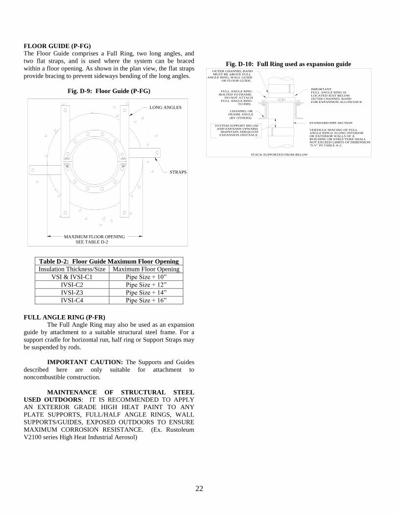
22
FLOOR GUIDE (P-FG)
The Floor Guide comprises a Full Ring, two long angles, and
two flat straps, and is used where the system can be braced
within a floor opening. As shown in the plan view, the flat straps
provide bracing to prevent sideways bending of the long angles.
Fig. D-9: Floor Guide (P-FG)
MAXIMUM FLOOR OPENINGSEE TABLE D-2
STRAPS
LONG ANGLES
Table D-2: Floor Guide Maximum Floor Opening
Insulation Thickness/Size Maximum Floor Opening
VSI & IVSI-C1 Pipe Size + 10”
IVSI-C2 Pipe Size + 12”
IVSI-Z3 Pipe Size + 14”
IVSI-C4 Pipe Size + 16”
FULL ANGLE RING (P-FR)
The Full Angle Ring may also be used as an expansion
guide by attachment to a suitable structural steel frame. For a
support cradle for horizontal run, half ring or Support Straps may
be suspended by rods.
IMPORTANT CAUTION: The Supports and Guides
described here are only suitable for attachment to
noncombustible construction.
MAINTENANCE OF STRUCTURAL STEEL
USED OUTDOORS: IT IS RECOMMENDED TO APPLY
AN EXTERIOR GRADE HIGH HEAT PAINT TO ANY
PLATE SUPPORTS, FULL/HALF ANGLE RINGS, WALL
SUPPORTS/GUIDES, EXPOSED OUTDOORS TO ENSURE
MAXIMUM CORROSION RESISTANCE. (Ex. Rustoleum
V2100 series High Heat Industrial Aerosol)
Fig. D-10: Full Ring used as expansion guide
FOR EXPANSION ALLOWANCE.OUTER CHANNEL BANDLOCATED JUST BELOWFULL ANGLE RING ISIMPORTANT
STANDARD PIPE SECTION
(BY OTHERS)
FRAME ANGLECHANNEL OR
TO PIPE.FULL ANGLE RING
DO NOT ATTACHBOLTED TO FRAME.
FULL ANGLE RING
OR FLOOR GUIDE.ANGLE RING, WALL GUIDE
MUST BE ABOVE FULLOUTER CHANNEL BAND
STACK SUPPORTED FROM BELOW
EXPANSION DISTANCE.MAINTAIN ADEQUATE
AND EXPANDS UPWARD.SYSTEM SUPPORT BELOW
"S-V" IN TABLE A-2.NOT EXCEED LIMITS OF DIMENSIONBUILDING OR STRUCTURE SHALLOR EXTERIOR WALLS OF AANGLE RINGS ALONG INTERIORVERTICLE SPACING OF FULL
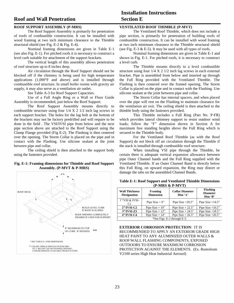
23
ROOF SUPPORT ASSEMBLY (P-MRS)
The Roof Support Assembly is primarily for penetration
of roofs of combustible construction. It can be installed with
wood framing at two inch minimum clearance to the Thimble
structural shield (see Fig. E-2 & Fig. E-4).
Nominal framing dimensions are given in Table E-1
(see also Fig. E-1). For pitched roofs it is necessary to construct a
level curb suitable for attachment of the support brackets.
The vertical length of this assembly allows penetration
of roof structure up to 8 inches deep.
Air circulation through the Roof Support should not be
blocked off if the chimney is being used for high temperature
applications (1,000°F and above) and is installed through
combustible roof structure. In small boiler rooms with gravity air
supply, it may also serve as a ventilation air outlet.
See Table A-3 for Roof Support Capacities.
Use of a Full Angle Ring or a Wall or Floor Guide
Assembly is recommended, just below the Roof Support.
The Roof Support Assembly mounts directly to
combustible structure using four 1/4 X 2 1/2 inch lag screws in
each support bracket. The holes for the lag bolt at the bottom of
the brackets may not be factory predrilled and will require to be
done in the field . The VSI/IVSI pipe from below and the next
pipe section above are attached to the Roof Support using the
Clamp Flange provided (Fig E-2). The Flashing is then centered
over the opening. The Storm Collar is placed on the pipe and in
contact with the Flashing. Use silicone sealant at the joint
between pipe and collar.
The ceiling shield is then attached to the support body
using the fasteners provided.
Fig. E-1: Framing dimensions for Thimble and Roof Support
Assembly. (P-MVT & P-MRS)
ROOF DECK
IF ROOF IS SLOPEDBUILD LEVEL CURB
FRAMED IF USED FOR SUPPORTROOF OPENING COMPLETELY
IF NEEDED)OF CURB
8" MAXIMUM (TO TOP
**
OF 3" BELOW CEILING/FRAMED OPENING.** CEILING SHIELD SHOULD EXTEND MIN.
* SEE TABLE E-1 FOR DIMENSIONS
**
LONGER SHEILDS AVAILABLE FROM FACTORY.
VENTILATED ROOF THIMBLE (P-MVT)
The Ventilated Roof Thimble, which does not include a
pipe section, is primarily for penetration of building roofs of
combustible construction. It can be installed with wood framing
at two inch minimum clearance to the Thimble structural shield
(see Fig. E-3 & E-5). It may be used with all types of roofs.
Nominal framing dimensions are given in Table E-1 and
shown in Fig. E-1. For pitched roofs, it is necessary to construct
a level curb.
The Thimble mounts directly to a level combustible
structure using four 1/4 X 2 1/2 inch lag screws in each external
bracket. Pipe is assembled from below and inserted up through
the Full Ring provided with the Ventilated Thimble. The
Flashing is then centered over the framed opening. The Storm
Collar is placed on the pipe and in contact with the Flashing. Use
silicone sealant at the joint between pipe and collar.
The Storm Collar has internal spacers, and when placed
over the pipe will rest on the Flashing to maintain clearance for
the ventilation air exit. The ceiling shield is then attached to the
thimble body using the fasteners provided.
This Thimble includes a Full Ring (Part No. P-FR)
which provides lateral chimney support to resist outdoor wind
loads; follow the “F” dimension shown in Section A for
maximum free standing heights above the Full Ring which is
secured to the Thimble body.
For the Ventilated Roof Thimble (as with the Roof
Support) do not block off air circulation through the Thimble if
the stack is installed through combustible roof structure.
When installing VSI pipe through the Thimble, be
certain there is adequate vertical expansion allowance between
pipe Outer Channel bands and the Full Ring supplied with the
Ventilated Thimble. If an Outer Channel Band is directly below
this Full Ring, on upward expansion, the Ring may distort or
damage the tabs on the assembled Channel Bands.
Table E-1: Roof Support and Ventilated Thimble Dimensions
(P-MRS & P-MVT)
Wall Thickness
/Designation
Framing
Dimension
Collar Diameter
Dim ‘A’
Flashing
Diameter
Dim ‘B’
1”/VSI & IVSI-
C1 Pipe Size + 8” Pipe Size +20.5” Pipe Size +14.5”
2”/IVSI-C2 Pipe Size + 10” Pipe Size + 22.5” Pipe Size +16.5”
3”/IVSI-Z3 Pipe Size + 12” Pipe Size + 24.5” Pipe Size +18.5”
4”/IVSI-C4 Pipe Size + 14” Pipe Size + 26.5” Pipe Size +20.5”
*See Figs. E-2 through E-5.
EXTERIOR CORROSION PROTECTION: IT IS
RECOMMENDED TO APPLY AN EXTERIOR GRADE HIGH
HEAT PAINT TO ANY ALUMINIZED OUTER WALLS &
ROOF/WALL FLASHING COMPONENTS, EXPOSED
OUTDOORS TO ENSURE MAXIMUM CORROSION
PROTECTION AGAINST THE ELEMENTS. (Ex. Rustoleum
V2100 series High Heat Industrial Aerosol)
Roof and Wall Penetration
Installation Instructions
Section E
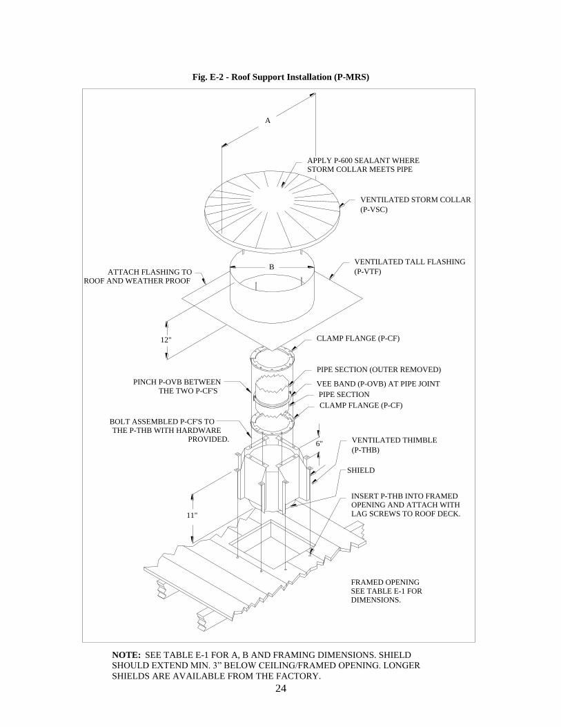
24
Fig. E-2 - Roof Support Installation (P-MRS)
SHIELD
A
LAG SCREWS TO ROOF DECK.
OPENING AND ATTACH WITHINSERT P-THB INTO FRAMED
(P-THB)
VENTILATED THIMBLE
DIMENSIONS.SEE TABLE E-1 FORFRAMED OPENING
(P-VTF)
VENTILATED TALL FLASHING
(P-VSC)
VENTILATED STORM COLLAR
STORM COLLAR MEETS PIPEAPPLY P-600 SEALANT WHERE
CLAMP FLANGE (P-CF)
VEE BAND (P-OVB) AT PIPE JOINT
CLAMP FLANGE (P-CF)
THE TWO P-CF'SPINCH P-OVB BETWEEN
PROVIDED.THE P-THB WITH HARDWARE
BOLT ASSEMBLED P-CF'S TO
PIPE SECTION (OUTER REMOVED)
PIPE SECTION
ROOF AND WEATHER PROOFATTACH FLASHING TO
6"
11"
12"
B
NOTE: SEE TABLE E-1 FOR A, B AND FRAMING DIMENSIONS. SHIELD
SHOULD EXTEND MIN. 3” BELOW CEILING/FRAMED OPENING. LONGER
SHIELDS ARE AVAILABLE FROM THE FACTORY.
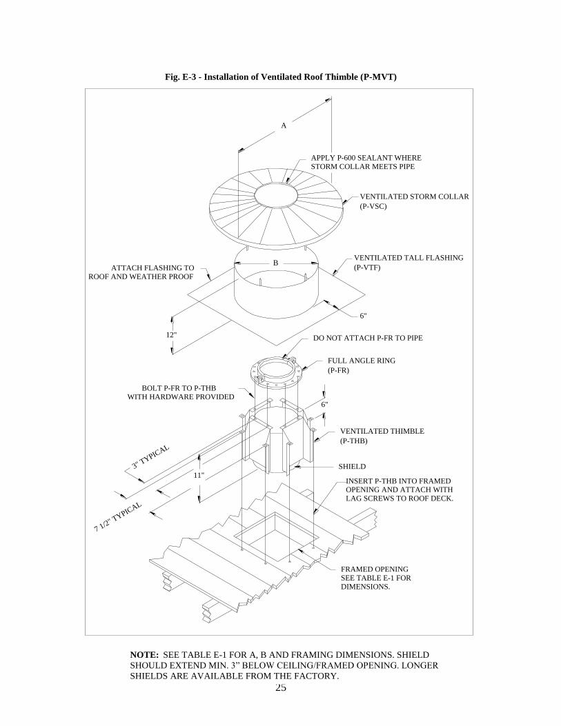
25
Fig. E-3 - Installation of Ventilated Roof Thimble (P-MVT)
SHIELD
(P-VSC)
VENTILATED STORM COLLAR
(P-VTF)
VENTILATED TALL FLASHING
(P-FR)
FULL ANGLE RING
(P-THB)
VENTILATED THIMBLE
DIMENSIONS.SEE TABLE E-1 FORFRAMED OPENING
STORM COLLAR MEETS PIPEAPPLY P-600 SEALANT WHERE
WITH HARDWARE PROVIDEDBOLT P-FR TO P-THB
DO NOT ATTACH P-FR TO PIPE
ROOF AND WEATHER PROOFATTACH FLASHING TO
LAG SCREWS TO ROOF DECK.OPENING AND ATTACH WITHINSERT P-THB INTO FRAMED
11"
6"
12"
6"
B
A
7 1/2" TYPIC
AL
3" TYPIC
AL
NOTE: SEE TABLE E-1 FOR A, B AND FRAMING DIMENSIONS. SHIELD
SHOULD EXTEND MIN. 3” BELOW CEILING/FRAMED OPENING. LONGER
SHIELDS ARE AVAILABLE FROM THE FACTORY.
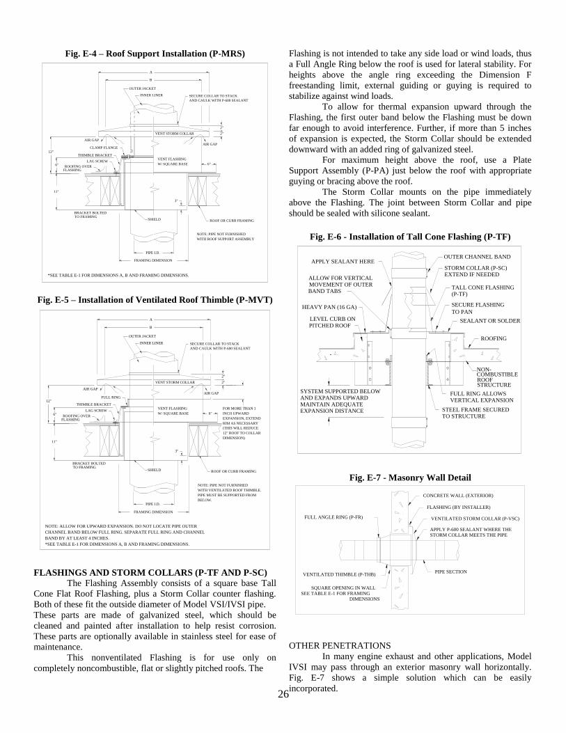
26
Fig. E-4 – Roof Support Installation (P-MRS)
2"
AND CAULK WITH P-600 SEALANT
SECURE COLLAR TO STACK
6"
AIR GAP
3"
WITH ROOF SUPPORT ASSEMBLY
NOTE: PIPE NOT FURNISHED
ROOF OR CURB FRAMING
2"
B
A
OUTER JACKET
LAG SCREW
THIMBLE BRACKET
AIR GAP
FLASHINGROOFING OVER
CLAMP FLANGE
SHIELD
PIPE I.D.
TO FRAMINGBRACKET BOLTED
12"
6"
11"
*SEE TABLE E-1 FOR DIMENSIONS A, B AND FRAMING DIMENSIONS.
W/ SQUARE BASE
VENT FLASHING
VENT STORM COLLAR
FRAMING DIMENSION
INNER LINER
Fig. E-5 – Installation of Ventilated Roof Thimble (P-MVT)
INNER LINER
FRAMING DIMENSION
VENT STORM COLLAR
VENT FLASHING
W/ SQUARE BASE
NOTE: ALLOW FOR UPWARD EXPANSION. DO NOT LOCATE PIPE OUTER
CHANNEL BAND BELOW FULL RING. SEPARATE FULL RING AND CHANNEL
*SEE TABLE E-1 FOR DIMENSIONS A, B AND FRAMING DIMENSIONS.
BAND BY AT LEAST 4 INCHES.
11"
6"
12"
BRACKET BOLTEDTO FRAMING
PIPE I.D.
SHIELD
FULL RING
ROOFING OVERFLASHING
AIR GAP
THIMBLE BRACKET
LAG SCREW
OUTER JACKET
A
B
2"
12" ROOF TO COLLAR
ROOF OR CURB FRAMING
NOTE: PIPE NOT FURNISHED
WITH VENTILATED ROOF THIMBLE.
PIPE MUST BE SUPPORTED FROM
BELOW.
3"
AIR GAP
6" INCH UPWARD
EXPANSION, EXTEND
RIM AS NECESSARY
(THIS WILL REDUCE
DIMENSION)
FOR MORE THAN 1
SECURE COLLAR TO STACK
AND CAULK WITH P-600 SEALANT
2"
FLASHINGS AND STORM COLLARS (P-TF AND P-SC)
The Flashing Assembly consists of a square base Tall
Cone Flat Roof Flashing, plus a Storm Collar counter flashing.
Both of these fit the outside diameter of Model VSI/IVSI pipe.
These parts are made of galvanized steel, which should be
cleaned and painted after installation to help resist corrosion.
These parts are optionally available in stainless steel for ease of
maintenance.
This nonventilated Flashing is for use only on
completely noncombustible, flat or slightly pitched roofs. The
Flashing is not intended to take any side load or wind loads, thus
a Full Angle Ring below the roof is used for lateral stability. For
heights above the angle ring exceeding the Dimension F
freestanding limit, external guiding or guying is required to
stabilize against wind loads.
To allow for thermal expansion upward through the
Flashing, the first outer band below the Flashing must be down
far enough to avoid interference. Further, if more than 5 inches
of expansion is expected, the Storm Collar should be extended
downward with an added ring of galvanized steel.
For maximum height above the roof, use a Plate
Support Assembly (P-PA) just below the roof with appropriate
guying or bracing above the roof.
The Storm Collar mounts on the pipe immediately
above the Flashing. The joint between Storm Collar and pipe
should be sealed with silicone sealant.
Fig. E-6 - Installation of Tall Cone Flashing (P-TF)
TO PAN
(P-TF)
STORM COLLAR (P-SC)EXTEND IF NEEDED
TALL CONE FLASHING
SECURE FLASHING
SEALANT OR SOLDER
ROOFING
FULL RING ALLOWSVERTICAL EXPANSION
STEEL FRAME SECURED
OUTER CHANNEL BANDAPPLY SEALANT HERE
SYSTEM SUPPORTED BELOWAND EXPANDS UPWARDMAINTAIN ADEQUATEEXPANSION DISTANCE
BAND TABSMOVEMENT OF OUTERALLOW FOR VERTICAL
HEAVY PAN (16 GA)
LEVEL CURB ONPITCHED ROOF
TO STRUCTURE
NON-COMBUSTIBLEROOFSTRUCTURE
Fig. E-7 - Masonry Wall Detail
CONCRETE WALL (EXTERIOR)
VENTILATED STORM COLLAR (P-VSC)
PIPE SECTIONVENTILATED THIMBLE (P-THB)
FULL ANGLE RING (P-FR)
FLASHING (BY INSTALLER)
STORM COLLAR MEETS THE PIPEAPPLY P-600 SEALANT WHERE THE
DIMENSIONSSEE TABLE E-1 FOR FRAMING
SQUARE OPENING IN WALL
OTHER PENETRATIONS
In many engine exhaust and other applications, Model
IVSI may pass through an exterior masonry wall horizontally.
Fig. E-7 shows a simple solution which can be easily
incorporated.
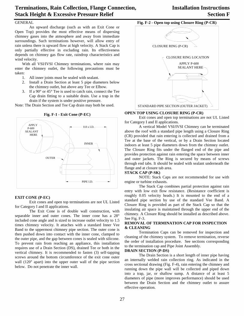
27
GENERAL
An upward discharge (such as with an Exit Cone or
Open Top) provides the most effective means of dispersing
chimney gases into the atmosphere and away from immediate
surroundings. Such terminations however, will allow entry of
rain unless there is upward flow at high velocity. A Stack Cap is
only partially effective in excluding rain. Its effectiveness
depends on chimney gas flow rate, raindrop characteristics and
wind velocity.
With all VSI/IVSI Chimney terminations, where rain may
enter the chimney outlet, the following precautions must be
taken:
1. All inner joints must be sealed with sealant.
2. Install a Drain Section at least 5 pipe diameters below
the chimney outlet, but above any Tee or Elbow.
3. If a 90° or 45° Tee is used to catch rain, connect the Tee
Cap drain fitting to a suitable drain. Use a trap in the
drain if the system is under positive pressure.
Note: The Drain Section and Tee Cap drain may both be used.
Fig. F-1 - Exit Cone (P-EC)
PIPE I.D.
0.8 x I.D.
INNER
OUTER
APPLYP-600
SEALANTHERE
EXIT CONE (P-EC)
Exit cones and open top terminations are not UL Listed
for Category I and II applications.
The Exit Cone is of double wall construction, with
separable inner and outer cones. The inner cone has a 28°
included cone angle and is sized to increase outlet velocity to 1.5
times chimney velocity. It attaches with a standard Inner Vee
Band to the uppermost chimney pipe section. The outer cone is
then pushed down into contact with the inner cone, clamped to
the outer pipe, and the gap between cones is sealed with silicone.
To prevent rain from reaching an appliance, this installation
requires use of a Drain Section (DS), drained Tee or both in the
vertical chimney. It is recommended to fasten (3) self-tapping
screws around the bottom circumference of the exit cone outer
wall (120° apart) into the upper outer wall of the pipe section
below. Do not penetrate the inner wall.
Terminations, Rain Collection, Flange Connection,
Stack Height & Excessive Pressure Relief
Installation Instructions
Section F
Fig. F-2 - Open top using Closure Ring (P-CR)
APPLY P-600SEALANT HERE
CLOSURE RING LOCATION
STANDARD PIPE SECTION (OUTER JACKET)
CLOSURE RING (P-CR)
OPEN TOP USING CLOSURE RING (P-CR)
Exit cones and open top terminations are not UL Listed
for Category I and II applications.
A vertical Model VSI/IVSI Chimney can be terminated
above the roof with a standard pipe length using a Closure Ring
(CR) provided that rain entering is collected and drained from a
Tee at the base of the vertical, or by a Drain Section located
indoors at least 5 pipe diameters down from the chimney outlet.
The Closure Ring fits under the flanged end of the pipe and
provides protection against rain entering the space between inner
and outer jackets. The Ring is secured by means of screws
through end tabs. It should be sealed with sealant underneath the
flange and at closure tab area.
STACK CAP (P-SK)
NOTE: Stack Caps are not recommended for use with
engine or turbine exhausts.
The Stack Cap combines partial protection against rain
entry with low exit flow resistance. (Resistance coefficient is
roughly 0.05 velocity heads.) It is mounted to the end of a
standard pipe section by use of the standard Vee Band. A
Closure Ring is provided as part of the Stack Cap so that the
insulating air space is maintained through the upper end of the
chimney. A Closure Ring should be installed as described above.
See Fig. F-3.
REMOVAL OF TERMINATION CAP FOR INSPECTION
& CLEANING
Termination Caps can be removed for inspection and
cleaning of the chimney system. To remove termination, reverse
the order of installation procedure. See sections corresponding
to the termination cap and Pipe Joint Assembly.
DRAIN SECTION (P-DS)
The Drain Section is a short length of inner pipe having
an internally welded rain collection ring. As indicated in the
cross sectional drawing (Fig. F-4), rain entering the chimney and
running down the pipe wall will be collected and piped down
into a trap, jar, or shallow sump. A distance of at least 5
diameters of pipe (more improves performance) should be used
between the Drain Section and the chimney outlet to assure
effective operation.
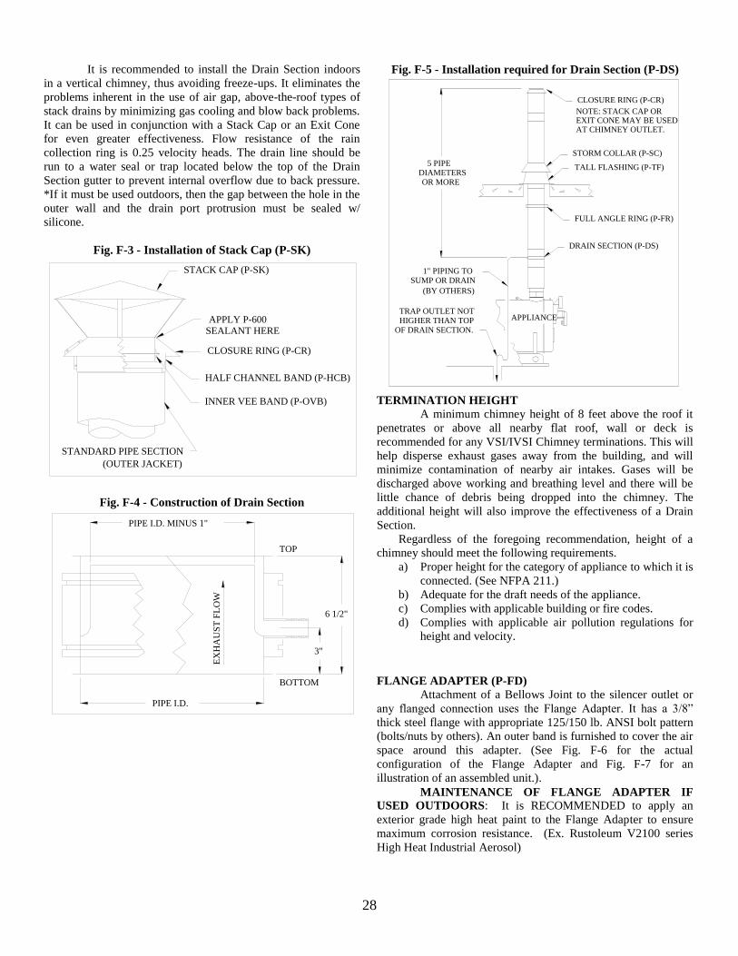
28
It is recommended to install the Drain Section indoors
in a vertical chimney, thus avoiding freeze-ups. It eliminates the
problems inherent in the use of air gap, above-the-roof types of
stack drains by minimizing gas cooling and blow back problems.
It can be used in conjunction with a Stack Cap or an Exit Cone
for even greater effectiveness. Flow resistance of the rain
collection ring is 0.25 velocity heads. The drain line should be
run to a water seal or trap located below the top of the Drain
Section gutter to prevent internal overflow due to back pressure.
*If it must be used outdoors, then the gap between the hole in the
outer wall and the drain port protrusion must be sealed w/
silicone.
Fig. F-3 - Installation of Stack Cap (P-SK)
SEALANT HERE
STANDARD PIPE SECTION
(OUTER JACKET)
CLOSURE RING (P-CR)
HALF CHANNEL BAND (P-HCB)
STACK CAP (P-SK)
INNER VEE BAND (P-OVB)
APPLY P-600
Fig. F-4 - Construction of Drain Section
EX
HA
US
T F
LO
W
BOTTOM
TOP
3"
6 1/2"
PIPE I.D. MINUS 1"
PIPE I.D.
Fig. F-5 - Installation required for Drain Section (P-DS)
AT CHIMNEY OUTLET.EXIT CONE MAY BE USEDNOTE: STACK CAP OR
APPLIANCE
CLOSURE RING (P-CR)
STORM COLLAR (P-SC)
TALL FLASHING (P-TF)
FULL ANGLE RING (P-FR)
TRAP OUTLET NOTHIGHER THAN TOP
OF DRAIN SECTION.
1" PIPING TOSUMP OR DRAIN
(BY OTHERS)
5 PIPEDIAMETERSOR MORE
DRAIN SECTION (P-DS)
TERMINATION HEIGHT
A minimum chimney height of 8 feet above the roof it
penetrates or above all nearby flat roof, wall or deck is
recommended for any VSI/IVSI Chimney terminations. This will
help disperse exhaust gases away from the building, and will
minimize contamination of nearby air intakes. Gases will be
discharged above working and breathing level and there will be
little chance of debris being dropped into the chimney. The
additional height will also improve the effectiveness of a Drain
Section.
Regardless of the foregoing recommendation, height of a
chimney should meet the following requirements.
a) Proper height for the category of appliance to which it is
connected. (See NFPA 211.)
b) Adequate for the draft needs of the appliance.
c) Complies with applicable building or fire codes.
d) Complies with applicable air pollution regulations for
height and velocity.
FLANGE ADAPTER (P-FD)
Attachment of a Bellows Joint to the silencer outlet or
any flanged connection uses the Flange Adapter. It has a 3/8”
thick steel flange with appropriate 125/150 lb. ANSI bolt pattern
(bolts/nuts by others). An outer band is furnished to cover the air
space around this adapter. (See Fig. F-6 for the actual
configuration of the Flange Adapter and Fig. F-7 for an
illustration of an assembled unit.).
MAINTENANCE OF FLANGE ADAPTER IF
USED OUTDOORS: It is RECOMMENDED to apply an
exterior grade high heat paint to the Flange Adapter to ensure
maximum corrosion resistance. (Ex. Rustoleum V2100 series
High Heat Industrial Aerosol)
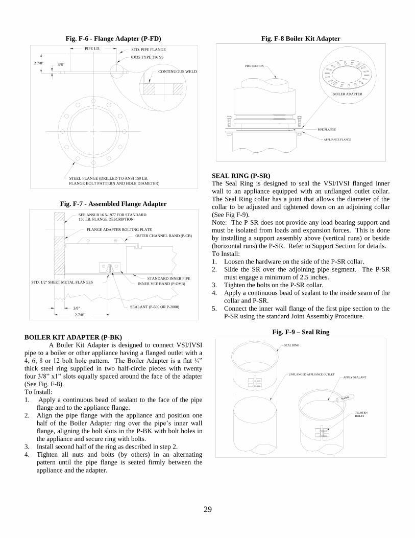
29
Fig. F-8 Boiler Kit Adapter
BOILER ADAPTER
PIPE FLANGE
APPLIANCE FLANGE
PIPE SECTION
SEAL RING (P-SR)
The Seal Ring is designed to seal the VSI/IVSI flanged inner
wall to an appliance equipped with an unflanged outlet collar.
The Seal Ring collar has a joint that allows the diameter of the
collar to be adjusted and tightened down on an adjoining collar
(See Fig F-9).
Note: The P-SR does not provide any load bearing support and
must be isolated from loads and expansion forces. This is done
by installing a support assembly above (vertical runs) or beside
(horizontal runs) the P-SR. Refer to Support Section for details.
To Install:
1. Loosen the hardware on the side of the P-SR collar.
2. Slide the SR over the adjoining pipe segment. The P-SR
must engage a minimum of 2.5 inches.
3. Tighten the bolts on the P-SR collar.
4. Apply a continuous bead of sealant to the inside seam of the
collar and P-SR.
5. Connect the inner wall flange of the first pipe section to the
P-SR using the standard Joint Assembly Procedure.
Fig. F-9 – Seal Ring
Sealant
SEAL RING
UNFLANGED APPLIANCE OUTLET
TIGHTENBOLTS
APPLY SEALANT
Fig. F-6 - Flange Adapter (P-FD)
STD. PIPE FLANGE
0.035 TYPE 316 SS
3/8"2 7/8"
STEEL FLANGE (DRILLED TO ANSI 150 LB.
FLANGE BOLT PATTERN AND HOLE DIAMETER)
CONTINUOUS WELD
PIPE I.D.
Fig. F-7 - Assembled Flange Adapter
150 LB. FLANGE DESCRIPTIONSEE ANSI B 16 5-1977 FOR STANDARD
FLANGE ADAPTER BOLTING PLATE
OUTER CHANNEL BAND (P-CB)
INNER VEE BAND (P-OVB)
SEALANT (P-600 OR P-2000)
STANDARD INNER PIPE
2-7/8"
3/8"
STD. 1/2" SHEET METAL FLANGES
BOILER KIT ADAPTER (P-BK)
A Boiler Kit Adapter is designed to connect VSI/IVSI
pipe to a boiler or other appliance having a flanged outlet with a
4, 6, 8 or 12 bolt hole pattern. The Boiler Adapter is a flat ¼”
thick steel ring supplied in two half-circle pieces with twenty
four 3/8” x1” slots equally spaced around the face of the adapter
(See Fig. F-8).
To Install:
1. Apply a continuous bead of sealant to the face of the pipe
flange and to the appliance flange.
2. Align the pipe flange with the appliance and position one
half of the Boiler Adapter ring over the pipe’s inner wall
flange, aligning the bolt slots in the P-BK with bolt holes in
the appliance and secure ring with bolts.
3. Install second half of the ring as described in step 2.
4. Tighten all nuts and bolts (by others) in an alternating
pattern until the pipe flange is seated firmly between the
appliance and the adapter.
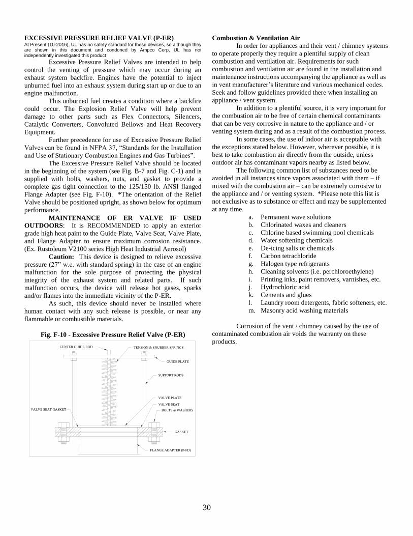
30
Combustion & Ventilation Air
In order for appliances and their vent / chimney systems
to operate properly they require a plentiful supply of clean
combustion and ventilation air. Requirements for such
combustion and ventilation air are found in the installation and
maintenance instructions accompanying the appliance as well as
in vent manufacturer’s literature and various mechanical codes.
Seek and follow guidelines provided there when installing an
appliance / vent system.
In addition to a plentiful source, it is very important for
the combustion air to be free of certain chemical contaminants
that can be very corrosive in nature to the appliance and / or
venting system during and as a result of the combustion process.
In some cases, the use of indoor air is acceptable with
the exceptions stated below. However, wherever possible, it is
best to take combustion air directly from the outside, unless
outdoor air has contaminant vapors nearby as listed below.
The following common list of substances need to be
avoided in all instances since vapors associated with them – if
mixed with the combustion air – can be extremely corrosive to
the appliance and / or venting system. *Please note this list is
not exclusive as to substance or effect and may be supplemented
at any time.
a. Permanent wave solutions
b. Chlorinated waxes and cleaners
c. Chlorine based swimming pool chemicals
d. Water softening chemicals
e. De-icing salts or chemicals
f. Carbon tetrachloride
g. Halogen type refrigerants
h. Cleaning solvents (i.e. perchloroethylene)
i. Printing inks, paint removers, varnishes, etc.
j. Hydrochloric acid
k. Cements and glues
l. Laundry room detergents, fabric softeners, etc.
m. Masonry acid washing materials
Corrosion of the vent / chimney caused by the use of
contaminated combustion air voids the warranty on these
products.
EXCESSIVE PRESSURE RELIEF VALVE (P-ER) At Present (10-2016), UL has no safety standard for these devices, so although they are shown in this document and condoned by Ampco Corp, UL has not independently investigated this product
Excessive Pressure Relief Valves are intended to help
control the venting of pressure which may occur during an
exhaust system backfire. Engines have the potential to inject
unburned fuel into an exhaust system during start up or due to an
engine malfunction.
This unburned fuel creates a condition where a backfire
could occur. The Explosion Relief Valve will help prevent
damage to other parts such as Flex Connectors, Silencers,
Catalytic Converters, Convoluted Bellows and Heat Recovery
Equipment.
Further precedence for use of Excessive Pressure Relief
Valves can be found in NFPA 37, “Standards for the Installation
and Use of Stationary Combustion Engines and Gas Turbines”.
The Excessive Pressure Relief Valve should be located
in the beginning of the system (see Fig. B-7 and Fig. C-1) and is
supplied with bolts, washers, nuts, and gasket to provide a
complete gas tight connection to the 125/150 lb. ANSI flanged
Flange Adapter (see Fig. F-10). *The orientation of the Relief
Valve should be positioned upright, as shown below for optimum
performance.
MAINTENANCE OF ER VALVE IF USED
OUTDOORS: It is RECOMMENDED to apply an exterior
grade high heat paint to the Guide Plate, Valve Seat, Valve Plate,
and Flange Adapter to ensure maximum corrosion resistance.
(Ex. Rustoleum V2100 series High Heat Industrial Aerosol)
Caution: This device is designed to relieve excessive
pressure (27” w.c. with standard spring) in the case of an engine
malfunction for the sole purpose of protecting the physical
integrity of the exhaust system and related parts. If such
malfunction occurs, the device will release hot gases, sparks
and/or flames into the immediate vicinity of the P-ER.
As such, this device should never be installed where
human contact with any such release is possible, or near any
flammable or combustible materials.
Fig. F-10 - Excessive Pressure Relief Valve (P-ER)
BOLTS & WASHERS
VALVE SEAT
VALVE PLATE
VALVE SEAT GASKET
FLANGE ADAPTER (P-FD)
SUPPORT RODS
TENSION & SNUBBER SPRINGSCENTER GUIDE ROD
GUIDE PLATE
GASKET
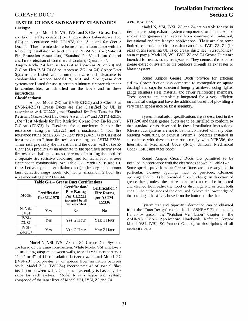
31
GREASE DUCT
Installation Instructions
Section G
INSTRUCTIONS AND SAFETY STANDARDS Listings:
Ampco Model N, VSI, IVSI and Z-Clear Grease Ducts
are Listed (safety certified) by Underwriters Laboratories, Inc.
(UL) in accordance with UL1978, the “Standard for Grease
Ducts”. They are intended to be installed in accordance with the
following installation instructions and NFPA 96, the (National
Fire Protection Association) “Standard for Ventilation Control
and Fire Protection of Commercial Cooking Operations”.
Ampco Model Z-Clear IVSI-Z3 (Also known as ZC or Z3) and
Z-Clear Plus IVSI-Z4 (Also known as ZC+ or Z4) Grease Duct
Systems are Listed with a minimum zero inch clearance to
combustibles. Ampco Models N, VSI and IVSI grease duct
systems are Listed for use at certain minimum airspace clearance
to combustibles, as identified on the labels and in these
instructions.
Classifications:
Ampco Model Z-Clear (IVSI-Z3/ZC) and Z-Clear Plus
(IVSI-Z4/ZC+) Grease Ducts are also Classified by UL in
accordance with UL2221, the “Standard for Fire Tests for Fire
Resistant Grease Duct Enclosure Assemblies” and ASTM-E2336
, the “Test Methods for Fire Resistive Grease Duct Enclosures”.
Z-Clear (ZC/Z3) is Classified for a maximum 2 hour fire
resistance rating per UL2221 and a maximum 1 hour fire
resistance rating per E2336. Z-Clear Plus (Z4/ZC+) is Classified
for a maximum 2 hour fire resistance rating per ASTM-E2336.
These ratings qualify the insulation and the outer wall of the Z-
Clear (ZC) products as an alternate to the specified hourly rated
fire resistive shaft enclosures (therefore eliminating the need for
a separate fire resistive enclosure) and for installation at zero
clearance to combustibles. See Table G-1. Model Z3 is also UL
Classified as a general ventilation duct (clothes dryers, bathroom
fans, domestic range hoods, etc) for a maximum 2 hour fire
resistance rating per ISO-6944.
Table G-1 – Grease Duct Certifications
Model Certification
Per UL1978
Certification/
Fire Rating
Per UL2221 (accepted by all
current codes)
Certification /
Fire Rating
per ASTM-
E2336
N, VSI,
IVSI Yes No No
IVSI-
Z3/ZC Yes Yes: 2 Hour Yes: 1 Hour
IVSI-
Z4/ZC+ Yes Yes: 2 Hour Yes: 2 Hour
Model N, VSI, IVSI, Z3 and Z4, Grease Duct Systems
are based on the same construction. While Model VSI employs a
1" insulating airspace between walls, Model IVSI incorporates a
1", 2" or 4" of fiber insulation between walls and Model ZC
(IVSI-Z3) incorporates 3" of special fiber insulation between
walls. Model ZC+ (IVSI-Z4) incorporates 4" of special fiber
insulation between walls. Component assembly is basically the
same for each system. Model N is a single wall system,
composed of the inner liner of Model VSI, IVSI, Z3 and Z4.
APPLICATION
Model N, VSI, IVSI, Z3 and Z4 are suitable for use in
installations using exhaust system components for the removal of
smoke and grease-laden vapors from commercial, industrial,
institutional and similar type applications. There are also some
limited residential applications that can utilize IVSI, Z3, Z4 (i.e
pizza ovens requiring UL listed grease duct: see “Surroundings”
on next page). Model N, VSI, IVSI, Z3 and Z4 Grease Ducts are
intended for use as complete systems. They connect the hood or
grease extractor system to the outdoors through an exhauster or
blower system.
Round Ampco Grease Ducts provide for efficient
airflow (lower friction loss compared to rectangular or square
ducting) and superior structural integrity achieved using lighter
gauge stainless steel material and fewer reinforcing members.
These systems are completely integrated for a very efficient
mechanical design and have the additional benefit of providing a
very clean appearance on final assembly.
System installation specifications are as described in the
NFPA96 and these grease ducts are to be installed to conform to
that standard or as described in these installation instructions.
(Grease duct systems are not to be interconnected with any other
building ventilating or exhaust system.) Systems installed in
accordance with these instructions comply with NFPA96, the
International Mechanical Code (IMC), Uniform Mechanical
Code (UMC) and other codes.
Round Ampco Grease Ducts are permitted to be
installed in accordance with the clearances shown in Table G-2.
Some special provisions for Grease Ducts are necessary and, in
particular, cleanout openings must be provided. Cleanout
openings should: 1) be provided at each change in direction of
grease ducts, unless the entire length of duct can be inspected
and cleaned from either the hood or discharge end or from both
ends, 2) be at the sides of the duct, and 3) have the lower edge of
the opening at least 1/2 above from the bottom of the duct.
System size and capacity information can be obtained
from: the “Duct Design” chapter in the ASHRAE Fundamentals
Handbook and/or the “Kitchen Ventilation” chapter in the
ASHRAE HVAC Applications Handbook. Refer to Ampco
Model VSI, IVSI, ZC Product Catalog for descriptions of all
necessary parts.
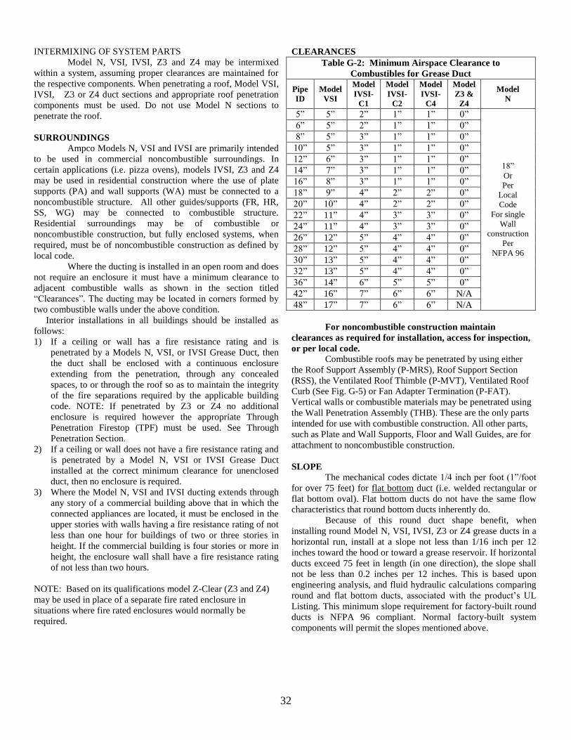
32
INTERMIXING OF SYSTEM PARTS
Model N, VSI, IVSI, Z3 and Z4 may be intermixed
within a system, assuming proper clearances are maintained for
the respective components. When penetrating a roof, Model VSI,
IVSI, Z3 or Z4 duct sections and appropriate roof penetration
components must be used. Do not use Model N sections to
penetrate the roof.
SURROUNDINGS
Ampco Models N, VSI and IVSI are primarily intended
to be used in commercial noncombustible surroundings. In
certain applications (i.e. pizza ovens), models IVSI, Z3 and Z4
may be used in residential construction where the use of plate
supports (PA) and wall supports (WA) must be connected to a
noncombustible structure. All other guides/supports (FR, HR,
SS, WG) may be connected to combustible structure.
Residential surroundings may be of combustible or
noncombustible construction, but fully enclosed systems, when
required, must be of noncombustible construction as defined by
local code.
Where the ducting is installed in an open room and does
not require an enclosure it must have a minimum clearance to
adjacent combustible walls as shown in the section titled
“Clearances”. The ducting may be located in corners formed by
two combustible walls under the above condition.
Interior installations in all buildings should be installed as
follows:
1) If a ceiling or wall has a fire resistance rating and is
penetrated by a Models N, VSI, or IVSI Grease Duct, then
the duct shall be enclosed with a continuous enclosure
extending from the penetration, through any concealed
spaces, to or through the roof so as to maintain the integrity
of the fire separations required by the applicable building
code. NOTE: If penetrated by Z3 or Z4 no additional
enclosure is required however the appropriate Through
Penetration Firestop (TPF) must be used. See Through
Penetration Section.
2) If a ceiling or wall does not have a fire resistance rating and
is penetrated by a Model N, VSI or IVSI Grease Duct
installed at the correct minimum clearance for unenclosed
duct, then no enclosure is required.
3) Where the Model N, VSI and IVSI ducting extends through
any story of a commercial building above that in which the
connected appliances are located, it must be enclosed in the
upper stories with walls having a fire resistance rating of not
less than one hour for buildings of two or three stories in
height. If the commercial building is four stories or more in
height, the enclosure wall shall have a fire resistance rating
of not less than two hours.
NOTE: Based on its qualifications model Z-Clear (Z3 and Z4)
may be used in place of a separate fire rated enclosure in
situations where fire rated enclosures would normally be
required.
CLEARANCES
Table G-2: Minimum Airspace Clearance to
Combustibles for Grease Duct
Pipe
ID
Model
VSI
Model
IVSI-
C1
Model
IVSI-
C2
Model
IVSI-
C4
Model
Z3 &
Z4
Model
N
5” 5” 2” 1” 1” 0”
18”
Or
Per
Local
Code
For single
Wall
construction
Per
NFPA 96
6” 5” 2” 1” 1” 0”
8” 5” 3” 1” 1” 0”
10” 5” 3” 1” 1” 0”
12” 6” 3” 1” 1” 0”
14” 7” 3” 1” 1” 0”
16” 8” 3” 1” 1” 0”
18” 9” 4” 2” 2” 0”
20” 10” 4” 2” 2” 0”
22” 11” 4” 3” 3” 0”
24” 11” 4” 3” 3” 0”
26” 12” 5” 4” 4” 0”
28” 12” 5” 4” 4” 0”
30” 13” 5” 4” 4” 0”
32” 13” 5” 4” 4” 0”
36” 14” 6” 5” 5” 0”
42” 16” 7” 6” 6” N/A
48” 17” 7” 6” 6” N/A
For noncombustible construction maintain
clearances as required for installation, access for inspection,
or per local code.
Combustible roofs may be penetrated by using either
the Roof Support Assembly (P-MRS), Roof Support Section
(RSS), the Ventilated Roof Thimble (P-MVT), Ventilated Roof
Curb (See Fig. G-5) or Fan Adapter Termination (P-FAT).
Vertical walls or combustible materials may be penetrated using
the Wall Penetration Assembly (THB). These are the only parts
intended for use with combustible construction. All other parts,
such as Plate and Wall Supports, Floor and Wall Guides, are for
attachment to noncombustible construction.
SLOPE
The mechanical codes dictate 1/4 inch per foot (1”/foot
for over 75 feet) for flat bottom duct (i.e. welded rectangular or
flat bottom oval). Flat bottom ducts do not have the same flow
characteristics that round bottom ducts inherently do.
Because of this round duct shape benefit, when
installing round Model N, VSI, IVSI, Z3 or Z4 grease ducts in a
horizontal run, install at a slope not less than 1/16 inch per 12
inches toward the hood or toward a grease reservoir. If horizontal
ducts exceed 75 feet in length (in one direction), the slope shall
not be less than 0.2 inches per 12 inches. This is based upon
engineering analysis, and fluid hydraulic calculations comparing
round and flat bottom ducts, associated with the product’s UL
Listing. This minimum slope requirement for factory-built round
ducts is NFPA 96 compliant. Normal factory-built system
components will permit the slopes mentioned above.
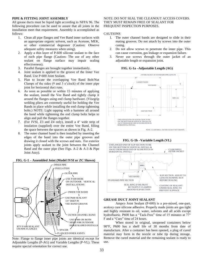
33
PIPE & FITTING JOINT ASSEMBLY
All grease ducts must be liquid tight according to NFPA 96. The
following procedure can be used to assure that all joints in the
installation meet that requirement. Assembly is accomplished as
follows:
1. Clean all pipe flanges and Vee Band inner surfaces with
an appropriate organic solvent, such as Acetone, MEK,
or other commercial degreaser (Caution: Observe
adequate safety measures when using).
2. Apply a thin layer of P-600 silicone sealant to the face
of each pipe flange (Caution: The use of any other
sealant on flange surface may impair sealing
effectiveness).
3. Parallel flanges are brought together immediately.
4. Joint sealant is applied to the groove of the Inner Vee
Band. Use P-600 Joint Sealant.
5. Plan to locate the overlapping Vee Band Bolt/Nut
Clamps of the sides (9 and 3 o’clock) of the inner pipe
joint for horizontal duct runs.
6. As soon as possible or within 15 minutes of applying
the sealant, install the Vee Band and tightly clamp it
around the flanges using end clamp hardware. (Visegrip
welding pliers are extremely useful for holding the Vee
Bands in place while installing the end clamp tightening
bolts.) NOTE: Light tapping with a hammer all around
the band while tightening the end clamp bolts helps to
align and pull the flanges together.
7. (For IVSI, Z3 and Z4 only), install a 4" wide strip of
insulation (supplied) over the entire Vee Band, filling
the space between the spacers as shown in Fig. A-2.
8. The outer channel band is then installed by inserting the
edges of the band into the outer pipe grooves and
drawing it closed with the screws and nuts. For exterior
joints apply sealant to the joint between the Channel
Band and the outer pipe (See Figs. A-2 & A-3 & Pipe
Joint Assy).
FIG. G-1 – Assembled Joint (Model IVSI or ZC Shown)
USE P-600 ON BOTH
HORIZ/SLOPED INSTALLS
SIDES FOR OUTDOOR
ON PIPE FLANGESRTV P-600 SEALANT
OUTER PIPE
VEE BAND GROOVE
VERTICAL
USE P-600 HERE
1/4" DEEP IN
USE P600 SEALANT
INSTALLATIONS
ON OUTDOOR
OUTER CHANNEL BAND
INNER VEE BAND
INSULATION
INNER PIPE
FLANGED INNER JOINTS
SPACER
Note: Flange to flange inner pipe joints are identical except for
Adjustable Lengths (P-AG) and Variable Lengths (P-VL). These
require special orientation for correct use.
NOTE: DO NOT SEAL THE CLEANOUT ACCESS COVERS.
THEY MUST REMAIN FREE OF SEALANT FOR
FREQUENT INSPECTION PURPOSES.
CAUTIONS
1. The outer channel bands are designed to slide in their
mating grooves. Do not attach by screws into the outer
casing.
2. Do not allow screws to penetrate the inner pipe. This
can cause corrosion, gas leakage or expansion failure.
3. Never use screws through the outer jacket of an
adjustable length or expansion joint.
FIG. G-1a –Adjustable Length (AG)
AWAY FROM HIGH END OF SLOPE/PITCH INHORIZONTAL INSTALL
x
30"
GASKET BAND
VEE BAND
SLIP SECTION
ON THE BOTTOM IN VERTICAL INSTALL &UNFLANGED END OF SLIP SECTION TO BE
OUTER JACKET OF STANDARD PIPE LENGTH
PIPE I.D.
NOTE: CLAM SHELL OUTER JACKET NOT SHOWN.
FIG. G-1b –Variable Length (VL)
VEE BAND
SEAL RING (P-SR) MUSTBE TIGHTLY CLAMPED
AROUND SLIP SECTION
SLIP SECTION. ADJUST TOLENGTH IN PIPING RUNBEFORE SEALING
COATING OF SEALANTUNDER SEAL RING TOPREVENT SLIPPAGE
STANDARD PIPE SECTION
CLAM SHELLON THE BOTTOM IN VERTICAL INSTALL &UNFLANGED END OF SLIP SECTION TO BE
AWAY FROM HIGH END OF SLOPE/PITCH INHORIZONTAL INSTALL OUTER JACKET
GREASE DUCT JOINT SEALANT
Ampco Joint Sealant (P-600) is a pre-mixed, one-part,
acetoxy cure silicone adhesive. Properly made joints are gas tight
and highly resistant to oil, water, solvents and all acids except
hydrofluoric. P600 has a “Tack-Free” time of 15 minutes at 77°
F and a “Cure” time of 24 hours.
When stored in original, unopened containers below
90°F, P600 has a shelf life of 30 months from date of
manufacture. After a container has been opened, a plug of cured
material may form in the nozzle or tube tip during storage.
Remove the cured material and the remaining sealant is ready to
use.
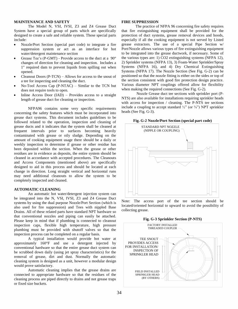
34
MAINTENANCE AND SAFETY
The Model N, VSI, IVSI, Z3 and Z4 Grease Duct
System have a special group of parts which are specifically
designed to create a safe and reliable system. Those special parts
include:
Nozzle/Port Section (special part code) to integrate a fire
suppression system or act as an interface for hot
water/detergent maintenance section
Grease Tee’s (P-GMT) - Provide access to the duct at a 90°
changes of direction for cleaning and inspection. Includes a
1" required dam to prevent liquids from spilling out when
opened.
Cleanout Doors (P-TCN) – Allows for access to the snout of
a tee for inspecting and cleaning the duct.
No-Tool Access Cap (P-NTAC) – Similar to the TCN but
does not require tools to open.
Inline Access Door (IAD) – Provides access to a straight
length of grease duct for cleaning or inspection.
NFPA96 contains some very specific requirements
concerning the safety features which must be incorporated into
grease duct systems. This document includes guidelines to be
followed related to the operation, inspection and cleaning of
grease ducts and it indicates that the system shall be cleaned at
frequent intervals prior to surfaces becoming heavily
contaminated with grease or oily sludge. Depending on the
amount of cooking equipment usage there should be a daily or
weekly inspection to determine if grease or other residue has
been deposited within the section. When the grease or other
residues are in evidence as deposits, the entire system should be
cleaned in accordance with accepted procedures. The Cleanouts
and Access Components (mentioned above) are specifically
designed to aid in this process and should be located at each
change in direction. Long straight vertical and horizontal runs
may need additional cleanouts to allow the system to be
completely inspected and cleaned.
AUTOMATIC CLEANING
An automatic hot water/detergent injection system can
be integrated into the N, VSI, IVSI, Z3 and Z4 Grease Duct
systems by using the dual purpose Nozzle/Port Section (which is
also used for fire suppression) and Tees with nippled Base
Drains. All of these related parts have standard NPT hardware so
that conventional nozzles and piping can easily be attached.
Please keep in mind that if plumbing is connected to cleanout
inspection caps, flexible high temperature, high pressure
plumbing must be provided with shutoff valves so that the
inspection process can be completed on a regular basis.
A typical installation would provide hot water at
approximately 160°F and use a detergent injected by
conventional hardware so that the entire grease duct system can
be scrubbed down daily (using jet spray characteristics) for the
removal of grease, dirt and dust. Normally the automatic
cleaning system is designed as a unit, however a modular design
would prove satisfactory.
Automatic cleaning implies that the grease drains are
connected to appropriate hardware so that the residues of the
cleaning process are piped directly to drains and not grease traps
or fixed size buckets.
FIRE SUPPRESSION
The practice of NFPA 96 concerning fire safety requires
that fire extinguishing equipment shall be provided for the
protection of duct systems, grease removal devices and hoods,
especially if all the cooking equipment is not served by Listed
grease extractors. The use of a special Pipe Section w/
Port/Nozzle allows various types of fire extinguishing equipment
to be integrated into the grease ductwork, if necessary. Some of
the various types are: 1) CO2 extinguishing systems (NFPA 12),
2) Sprinkler systems (NFPA 13), 3) Foam-Water Sprinkler/Spray
Systems (NFPA 16), and 4) Dry Chemical Extinguishing
Systems (NFPA 17). The Nozzle Section (See Fig. G-2) can be
positioned so that the nozzle fitting is either on the sides or top of
the section consistent with good fire protection design practice.
Various diameter NPT couplings offered allow for flexibility
when making the required connections (See Fig. G-2).
Nozzle Grease duct tee sections with sprinkler port (P-
NTS) are also available for installations requiring sprinkler heads
with access for inspection / cleaning. The P-NTS tee sections
include a coupling to accept standard ½” (or ¾”) NPT sprinkler
heads (See Fig. G-3).
Fig. G-2 Nozzle/Port Section (special part code)
STANDARD NPT NOZZLE
(NIPPLE OR COUPLING)
Note: The access port of the tee section should be
located/oriented horizontal to upward to avoid the possibility of
collecting grease.
Fig. G-3 Sprinkler Section (P-NTS)
TEE SNOUT PROVIDES ACCESS
FOR INSTALLATION/INSPECTION OF
SPRINKLER HEAD
FACTORY INSTALLEDTHREADED COUPLER
FIELD INSTALLEDSPRINKLER HEAD
(BY OTHERS)
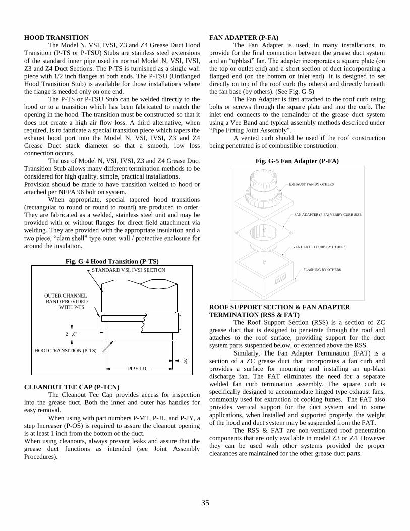
35
HOOD TRANSITION
The Model N, VSI, IVSI, Z3 and Z4 Grease Duct Hood
Transition (P-TS or P-TSU) Stubs are stainless steel extensions
of the standard inner pipe used in normal Model N, VSI, IVSI,
Z3 and Z4 Duct Sections. The P-TS is furnished as a single wall
piece with 1/2 inch flanges at both ends. The P-TSU (Unflanged
Hood Transition Stub) is available for those installations where
the flange is needed only on one end.
The P-TS or P-TSU Stub can be welded directly to the
hood or to a transition which has been fabricated to match the
opening in the hood. The transition must be constructed so that it
does not create a high air flow loss. A third alternative, when
required, is to fabricate a special transition piece which tapers the
exhaust hood port into the Model N, VSI, IVSI, Z3 and Z4
Grease Duct stack diameter so that a smooth, low loss
connection occurs.
The use of Model N, VSI, IVSI, Z3 and Z4 Grease Duct
Transition Stub allows many different termination methods to be
considered for high quality, simple, practical installations.
Provision should be made to have transition welded to hood or
attached per NFPA 96 bolt on system.
When appropriate, special tapered hood transitions
(rectangular to round or round to round) are produced to order.
They are fabricated as a welded, stainless steel unit and may be
provided with or without flanges for direct field attachment via
welding. They are provided with the appropriate insulation and a
two piece, “clam shell” type outer wall / protective enclosure for
around the insulation.
Fig. G-4 Hood Transition (P-TS)
HOOD TRANSITION (P-TS)
PIPE I.D.
"212
WITH P-TSBAND PROVIDED
OUTER CHANNEL
"21
STANDARD VSI, IVSI SECTION
CLEANOUT TEE CAP (P-TCN)
The Cleanout Tee Cap provides access for inspection
into the grease duct. Both the inner and outer has handles for
easy removal.
When using with part numbers P-MT, P-JL, and P-JY, a
step Increaser (P-OS) is required to assure the cleanout opening
is at least 1 inch from the bottom of the duct.
When using cleanouts, always prevent leaks and assure that the
grease duct functions as intended (see Joint Assembly
Procedures).
FAN ADAPTER (P-FA)
The Fan Adapter is used, in many installations, to
provide for the final connection between the grease duct system
and an “upblast” fan. The adapter incorporates a square plate (on
the top or outlet end) and a short section of duct incorporating a
flanged end (on the bottom or inlet end). It is designed to set
directly on top of the roof curb (by others) and directly beneath
the fan base (by others). (See Fig. G-5)
The Fan Adapter is first attached to the roof curb using
bolts or screws through the square plate and into the curb. The
inlet end connects to the remainder of the grease duct system
using a Vee Band and typical assembly methods described under
“Pipe Fitting Joint Assembly”.
A vented curb should be used if the roof construction
being penetrated is of combustible construction.
Fig. G-5 Fan Adapter (P-FA)
FLASHING BY OTHERS
VENTILATED CURB BY OTHERS
FAN ADAPTER (P-FA) VERIFY CURB SIZE
EXHAUST FAN BY OTHERS
ROOF SUPPORT SECTION & FAN ADAPTER
TERMINATION (RSS & FAT)
The Roof Support Section (RSS) is a section of ZC
grease duct that is designed to penetrate through the roof and
attaches to the roof surface, providing support for the duct
system parts suspended below, or extended above the RSS.
Similarly, The Fan Adapter Termination (FAT) is a
section of a ZC grease duct that incorporates a fan curb and
provides a surface for mounting and installing an up-blast
discharge fan. The FAT eliminates the need for a separate
welded fan curb termination assembly. The square curb is
specifically designed to accommodate hinged type exhaust fans,
commonly used for extraction of cooking fumes. The FAT also
provides vertical support for the duct system and in some
applications, when installed and supported properly, the weight
of the hood and duct system may be suspended from the FAT.
The RSS & FAT are non-ventilated roof penetration
components that are only available in model Z3 or Z4. However
they can be used with other systems provided the proper
clearances are maintained for the other grease duct parts.
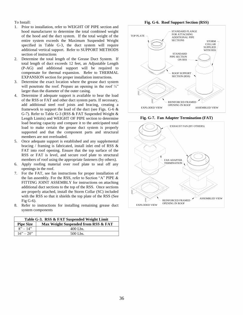
36
To Install:
1. Prior to installation, refer to WEIGHT OF PIPE section and
hood manufacturer to determine the total combined weight
of the hood and the duct system. If the total weight of the
entire system exceeds the Maximum Suspended Weight
specified in Table G-3, the duct system will require
additional vertical support. Refer to SUPPORT METHODS
section of instructions
2. Determine the total length of the Grease Duct System. If
total length of duct exceeds 12 feet, an Adjustable Length
(P-AG) and additional support will be required to
compensate for thermal expansion. Refer to THERMAL
EXPANSION section for proper installation instructions.
3. Determine the exact location where the grease duct system
will penetrate the roof. Prepare an opening in the roof ¼”
larger than the diameter of the outer casing.
4. Determine if adequate support is available to bear the load
of the RSS or FAT and other duct system parts. If necessary,
add additional steel roof joists and bracing, creating a
framework to support the load of the duct (see Figs. G-6 &
G-7). Refer to Table G-3 (RSS & FAT Suspended Weight &
Length Limits) and WEIGHT OF PIPE section to determine
load bearing capacity and compare it to the anticipated total
load to make certain the grease duct system is properly
supported and that the component parts and structural
members are not overloaded.
5. Once adequate support is established and any supplemental
bracing / framing is fabricated, install inlet end of RSS &
FAT into roof opening. Ensure that the top surface of the
RSS or FAT is level, and secure roof plate to structural
members of roof using the appropriate fasteners (by others).
6. Apply roofing material over roof plate to seal off any
openings in the roof.
7. For the FAT, see fan instructions for proper installation of
the fan assembly. For the RSS, refer to Section “A” PIPE &
FITTING JOINT ASSEMBLY for instructions on attaching
additional duct sections to the top of the RSS. Once sections
are properly attached, install the Storm Collar (SC) included
with the RSS so that it shields the top plate of the RSS (See
Fig G-6).
8. Refer to instructions for installing remaining grease duct
system components
Table G-3. RSS & FAT Suspended Weight Limit
Pipe Size Max Weight Suspended from RSS & FAT
8” – 14” 400 Lbs.
16” – 20” 500 Lbs.
Fig. G-6. Roof Support Section (RSS)
TOP PLATE
STANDARD FLANGEFOR ATTACHINGADDITIONAL PIPESECTIONS
ROOF SUPPORT
SECTION (RSS)
REINFORCED FRAMEDOPENING IN ROOF
STORMCOLLAR
SUPPLIEDWITH RSS
STANDARDPIPE SECTION
ON RSS
EXPLODED VIEW ASSEMBLED VIEW
Fig. G-7. Fan Adapter Termination (FAT)
EXHAUST FAN (BY OTHERS)
REINFORCED FRAMEDOPENING IN ROOF
FAN ADAPTERTERMINATION
ASSEMBLED VIEW
EXPLODED VIEW
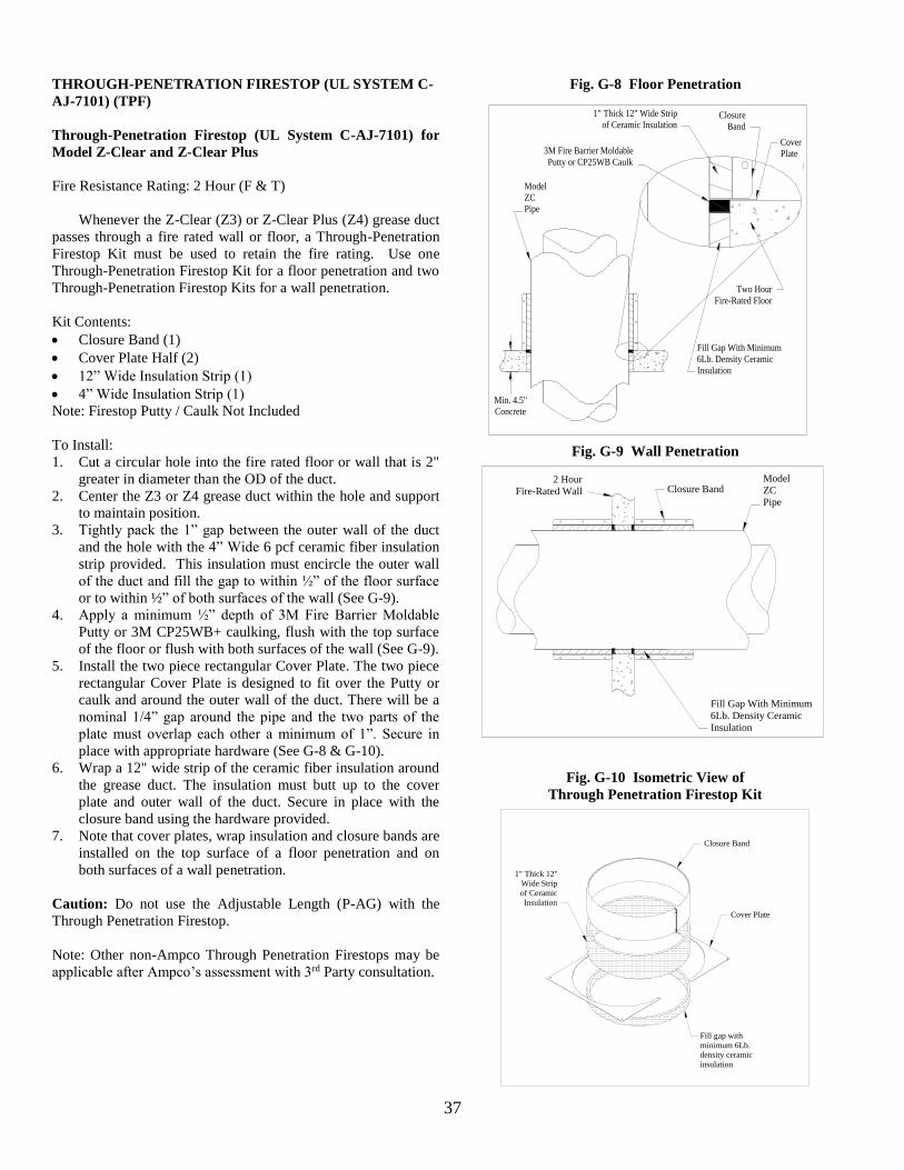
37
THROUGH-PENETRATION FIRESTOP (UL SYSTEM C-
AJ-7101) (TPF)
Through-Penetration Firestop (UL System C-AJ-7101) for
Model Z-Clear and Z-Clear Plus
Fire Resistance Rating: 2 Hour (F & T)
Whenever the Z-Clear (Z3) or Z-Clear Plus (Z4) grease duct
passes through a fire rated wall or floor, a Through-Penetration
Firestop Kit must be used to retain the fire rating. Use one
Through-Penetration Firestop Kit for a floor penetration and two
Through-Penetration Firestop Kits for a wall penetration.
Kit Contents:
Closure Band (1)
Cover Plate Half (2)
12” Wide Insulation Strip (1)
4” Wide Insulation Strip (1)
Note: Firestop Putty / Caulk Not Included
To Install:
1. Cut a circular hole into the fire rated floor or wall that is 2"
greater in diameter than the OD of the duct.
2. Center the Z3 or Z4 grease duct within the hole and support
to maintain position.
3. Tightly pack the 1” gap between the outer wall of the duct
and the hole with the 4” Wide 6 pcf ceramic fiber insulation
strip provided. This insulation must encircle the outer wall
of the duct and fill the gap to within ½” of the floor surface
or to within ½” of both surfaces of the wall (See G-9).
4. Apply a minimum ½” depth of 3M Fire Barrier Moldable
Putty or 3M CP25WB+ caulking, flush with the top surface
of the floor or flush with both surfaces of the wall (See G-9).
5. Install the two piece rectangular Cover Plate. The two piece
rectangular Cover Plate is designed to fit over the Putty or
caulk and around the outer wall of the duct. There will be a
nominal 1/4” gap around the pipe and the two parts of the
plate must overlap each other a minimum of 1”. Secure in
place with appropriate hardware (See G-8 & G-10).
6. Wrap a 12" wide strip of the ceramic fiber insulation around
the grease duct. The insulation must butt up to the cover
plate and outer wall of the duct. Secure in place with the
closure band using the hardware provided.
7. Note that cover plates, wrap insulation and closure bands are
installed on the top surface of a floor penetration and on
both surfaces of a wall penetration.
Caution: Do not use the Adjustable Length (P-AG) with the
Through Penetration Firestop.
Note: Other non-Ampco Through Penetration Firestops may be
applicable after Ampco’s assessment with 3rd Party consultation.
Fig. G-8 Floor Penetration
Model
ZC
Pipe
3M Fire Barrier Moldable
Putty or CP25WB Caulk
1" Thick 12" Wide Strip
of Ceramic InsulationClosure
Band
Cover
Plate
Two Hour
Fire-Rated Floor
Fill Gap With Minimum
6Lb. Density Ceramic
Insulation
Min. 4.5"
Concrete
Fig. G-9 Wall Penetration
ModelZC
Pipe
2 Hour
Fire-Rated Wall
Fill Gap With Minimum
6Lb. Density Ceramic
Insulation
Closure Band
Fig. G-10 Isometric View of
Through Penetration Firestop Kit
Fill gap with
minimum 6Lb.
density ceramic
insulation
Closure Band
Cover Plate
1" Thick 12"
Wide Strip
of Ceramic
Insulation
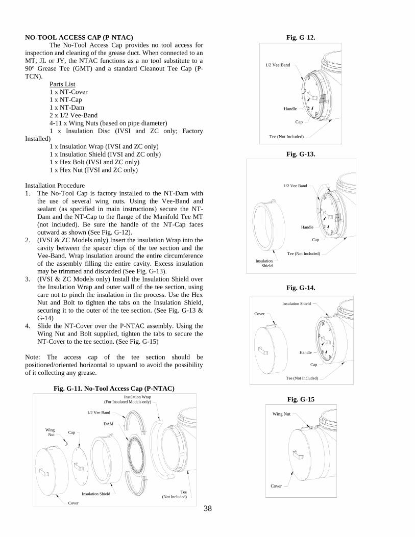
38
NO-TOOL ACCESS CAP (P-NTAC)
The No-Tool Access Cap provides no tool access for
inspection and cleaning of the grease duct. When connected to an
MT, JL or JY, the NTAC functions as a no tool substitute to a
90° Grease Tee (GMT) and a standard Cleanout Tee Cap (P-
TCN).
Parts List
1 x NT-Cover
1 x NT-Cap
1 x NT-Dam
2 x 1/2 Vee-Band
4-11 x Wing Nuts (based on pipe diameter)
1 x Insulation Disc (IVSI and ZC only; Factory
Installed)
1 x Insulation Wrap (IVSI and ZC only)
1 x Insulation Shield (IVSI and ZC only)
1 x Hex Bolt (IVSI and ZC only)
1 x Hex Nut (IVSI and ZC only)
Installation Procedure
1. The No-Tool Cap is factory installed to the NT-Dam with
the use of several wing nuts. Using the Vee-Band and
sealant (as specified in main instructions) secure the NT-
Dam and the NT-Cap to the flange of the Manifold Tee MT
(not included). Be sure the handle of the NT-Cap faces
outward as shown (See Fig. G-12).
2. (IVSI & ZC Models only) Insert the insulation Wrap into the
cavity between the spacer clips of the tee section and the
Vee-Band. Wrap insulation around the entire circumference
of the assembly filling the entire cavity. Excess insulation
may be trimmed and discarded (See Fig. G-13).
3. (IVSI & ZC Models only) Install the Insulation Shield over
the Insulation Wrap and outer wall of the tee section, using
care not to pinch the insulation in the process. Use the Hex
Nut and Bolt to tighten the tabs on the Insulation Shield,
securing it to the outer of the tee section. (See Fig. G-13 &
G-14)
4. Slide the NT-Cover over the P-NTAC assembly. Using the
Wing Nut and Bolt supplied, tighten the tabs to secure the
NT-Cover to the tee section. (See Fig. G-15)
Note: The access cap of the tee section should be
positioned/oriented horizontal to upward to avoid the possibility
of it collecting any grease.
Fig. G-11. No-Tool Access Cap (P-NTAC)
Tee
(Not Included)
Insulation Wrap
(For Insulated Models only)
DAM
1/2 Vee Band
Insulation Shield
Cap
Cover
Wing
Nut
Fig. G-12.
1/2 Vee Band
Tee (Not Included)
Cap
Handle
Fig. G-13.
Handle
Cap
Tee (Not Included)
1/2 Vee Band
Insulation
Shield
Fig. G-14.
Cap
Handle
Cover
Insulation Shield
Tee (Not Included)
Fig. G-15
Wing Nut
Cover
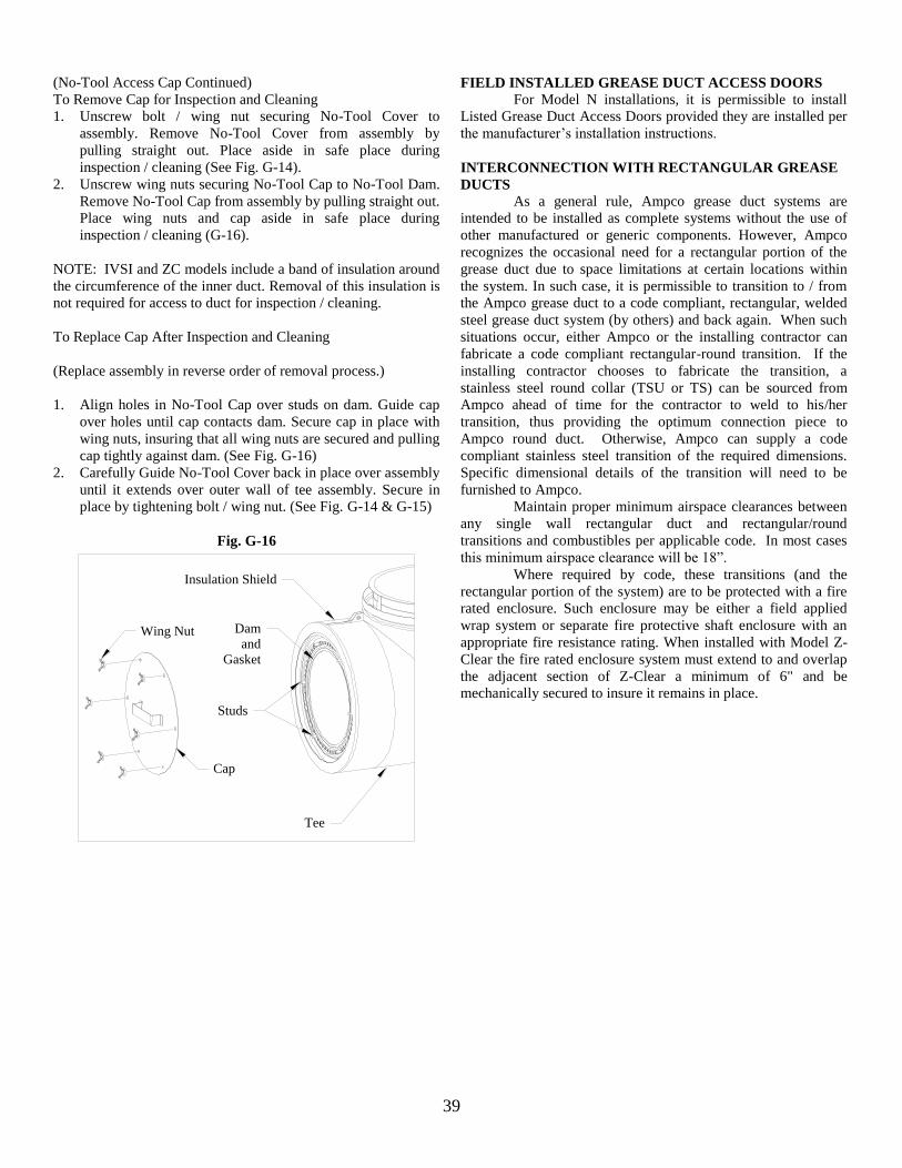
39
(No-Tool Access Cap Continued)
To Remove Cap for Inspection and Cleaning
1. Unscrew bolt / wing nut securing No-Tool Cover to
assembly. Remove No-Tool Cover from assembly by
pulling straight out. Place aside in safe place during
inspection / cleaning (See Fig. G-14).
2. Unscrew wing nuts securing No-Tool Cap to No-Tool Dam.
Remove No-Tool Cap from assembly by pulling straight out.
Place wing nuts and cap aside in safe place during
inspection / cleaning (G-16).
NOTE: IVSI and ZC models include a band of insulation around
the circumference of the inner duct. Removal of this insulation is
not required for access to duct for inspection / cleaning.
To Replace Cap After Inspection and Cleaning
(Replace assembly in reverse order of removal process.)
1. Align holes in No-Tool Cap over studs on dam. Guide cap
over holes until cap contacts dam. Secure cap in place with
wing nuts, insuring that all wing nuts are secured and pulling
cap tightly against dam. (See Fig. G-16)
2. Carefully Guide No-Tool Cover back in place over assembly
until it extends over outer wall of tee assembly. Secure in
place by tightening bolt / wing nut. (See Fig. G-14 & G-15)
Fig. G-16
Dam
and
Gasket
Wing Nut
Studs
Cap
Tee
Insulation Shield
FIELD INSTALLED GREASE DUCT ACCESS DOORS
For Model N installations, it is permissible to install
Listed Grease Duct Access Doors provided they are installed per
the manufacturer’s installation instructions.
INTERCONNECTION WITH RECTANGULAR GREASE
DUCTS
As a general rule, Ampco grease duct systems are
intended to be installed as complete systems without the use of
other manufactured or generic components. However, Ampco
recognizes the occasional need for a rectangular portion of the
grease duct due to space limitations at certain locations within
the system. In such case, it is permissible to transition to / from
the Ampco grease duct to a code compliant, rectangular, welded
steel grease duct system (by others) and back again. When such
situations occur, either Ampco or the installing contractor can
fabricate a code compliant rectangular-round transition. If the
installing contractor chooses to fabricate the transition, a
stainless steel round collar (TSU or TS) can be sourced from
Ampco ahead of time for the contractor to weld to his/her
transition, thus providing the optimum connection piece to
Ampco round duct. Otherwise, Ampco can supply a code
compliant stainless steel transition of the required dimensions.
Specific dimensional details of the transition will need to be
furnished to Ampco.
Maintain proper minimum airspace clearances between
any single wall rectangular duct and rectangular/round
transitions and combustibles per applicable code. In most cases
this minimum airspace clearance will be 18”.
Where required by code, these transitions (and the
rectangular portion of the system) are to be protected with a fire
rated enclosure. Such enclosure may be either a field applied
wrap system or separate fire protective shaft enclosure with an
appropriate fire resistance rating. When installed with Model Z-
Clear the fire rated enclosure system must extend to and overlap
the adjacent section of Z-Clear a minimum of 6" and be
mechanically secured to insure it remains in place.
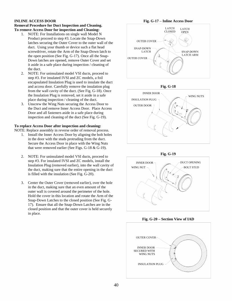
40
INLINE ACCESS DOOR
Removal Procedure for Duct Inspection and Cleaning.
To remove Access Door for inspection and Cleaning:
1. NOTE: For Installations on single wall Model N
Product proceed to step #3. Locate the Snap-Down
latches securing the Outer Cover to the outer wall of the
duct. Using your thumb or device such a flat head
screwdriver, rotate the Arm of the Snap-Down latch to
the open position (See Fig. G-17). Once all the Snap-
Down latches are opened, remove Outer Cover and set
it aside in a safe place during inspection / cleaning of
the duct.
2. NOTE: For uninsulated model VSI ducts, proceed to
step #3. For insulated IVSI and ZC models, a foil
encapsulated Insulation Plug is used to insulate the duct
and access door. Carefully remove the insulation plug
from the wall cavity of the duct. (See Fig. G-18). Once
the Insulation Plug is removed, set it aside in a safe
place during inspection / cleaning of the duct.
3. Unscrew the Wing Nuts securing the Access Door to
the Duct and remove Inner Access Door. Place Access
Door and all fasteners aside in a safe place during
inspection and cleaning of the duct (See Fig. G-19).
To replace Access Door after inspection and cleaning:
NOTE: Replace assembly in reverse order of removal process.
1. Install the Inner Access Door by aligning the bolt holes
in the door with the studs protruding from the duct.
Secure the Access Door in place with the Wing Nuts
that were removed earlier (See Figs. G-18 & G-19).
2. NOTE: For uninsulated model VSI ducts, proceed to
step #3. For insulated IVSI and ZC models, install the
Insulation Plug (removed earlier), into the wall cavity of
the duct, making sure that the entire opening in the duct
is filled with the insulation (See Fig. G-20).
3. Center the Outer Cover (removed earlier), over the hole
in the duct, making sure that an even amount of the
outer wall is covered around the perimeter of the hole.
Hold the cover in this location and rotate the Arm of the
Snap-Down Latches to the closed position (See Fig. G-
17). Ensure that all the Snap-Down Latches are in the
closed position and that the outer cover is held securely
in place.
Fig. G-17 – Inline Access Door
Fig. G-18
WING NUTSINNER DOOR
OUTER DOOR
INSULATION PLUG
Fig. G-19
BOLT STUD
DUCT OPENING
WING NUT
INNER DOOR
Fig. G-20 – Section View of IAD
INNER DOORSECURED WITH
WING NUTS
OUTER COVER
INSULATION PLUG
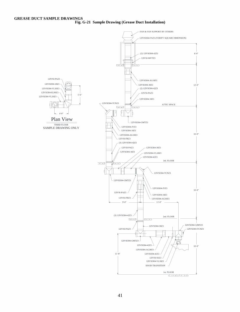
41
Fig. G-21 Sample Drawing (Grease Duct Installation)
4'-0"
5'-6"
THIRD FLOOR
12IVSI304-VL30Z3
12IVSI304-EL90Z3
12IVSI304-VL30Z3
12IVSI304-18Z3
12IVSI-PAZ3
SAMPLE DRAWING ONLY
Plan View
11'-8"
16'-0"
16'-0"
16'-0"
12'-0"
6'-0"
9'-0" 11'-0"
1st. FLOOR
2nd. FLOOR
HOOD TRANSITION
12IVSI304-VL18Z3
12IVSI304-TCNZ3
12IVSI304-12MTZ3
12IVSI-SSZ3
12IVSI304-42Z3
12IVSI304-AG30Z3
12IVSI304-42Z3
12IVSI304-GMTZ3
12IVSI304-30Z3
12IVSI-PAZ3
(3) 12IVSI304-42Z3
3rd. FLOOR
12IVSI-FRZ3 12IVSI304-AG30Z3
12IVSI304-18Z3
12IVSI304-JYZ3
12IVSI304-TCNZ3
12IVSI-PAZ3
12IVSI304-42Z3
12IVSI304-VL18Z3
12IVSI304-30Z3
12IVSI304-GMTZ3
12IVSI304-18Z3
12IVSI-PAZ3
ATTIC SPACE
(3) 12IVSI304-42Z3
12IVSI-FRZ3
12IVSI304-AG18Z3
12IVSI304-18Z3
12IVSI304-JYZ3
12IVSI304-TCNZ3
12IVSI304-GMTZ3
12IVSI304-18Z3
12IVSI-PAZ3
(2) 12IVSI304-42Z3
12IVSI304-30Z3
12IVSI304-AG18Z3
12IVSI-MVTZ3
(2) 12IVSI304-42Z3
12IVSI304-FAZ3 (VERIFY SQUARE DIMENSION)
FAN & FAN SUPPORT BY OTHERS
GREASE DUCT SAMPLE DRAWINGS
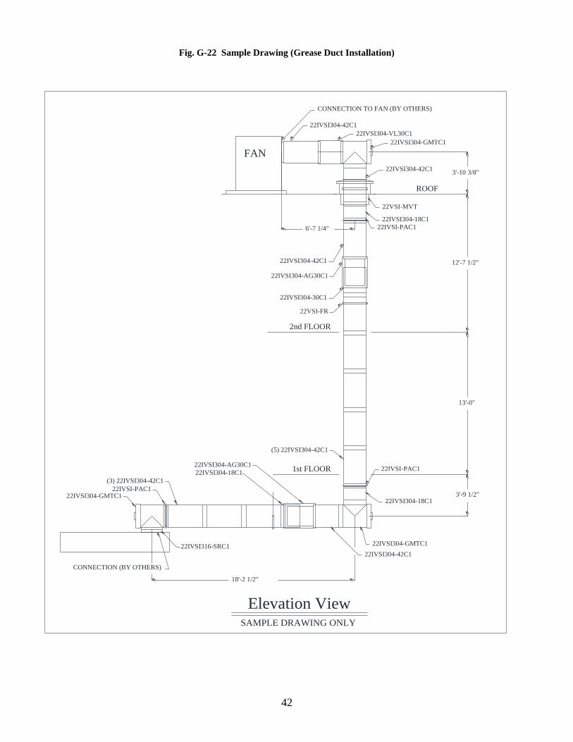
42
Fig. G-22 Sample Drawing (Grease Duct Installation)
Elevation ViewSAMPLE DRAWING ONLY
22IVSI304-42C1
18'-2 1/2"
3'-9 1/2"
13'-0"
12'-7 1/2"
3'-10 3/8"
6'-7 1/4"
22IVSI316-SRC1
22IVSI304-GMTC122IVSI-PAC1
(3) 22IVSI304-42C1
22IVSI304-18C1
22IVSI304-AG30C1
22IVSI304-42C1
22IVSI304-GMTC1
22IVSI304-18C1
22IVSI-PAC1
(5) 22IVSI304-42C1
22VSI-FR
22IVSI304-30C1
22IVSI304-AG30C1
22IVSI304-42C1
22IVSI-PAC1
22VSI-MVT
22IVSI304-18C1
22IVSI304-GMTC1
22IVSI304-VL30C1
22IVSI304-42C1
CONNECTION (BY OTHERS)
CONNECTION TO FAN (BY OTHERS)
ROOF
2nd FLOOR
1st FLOOR
FAN
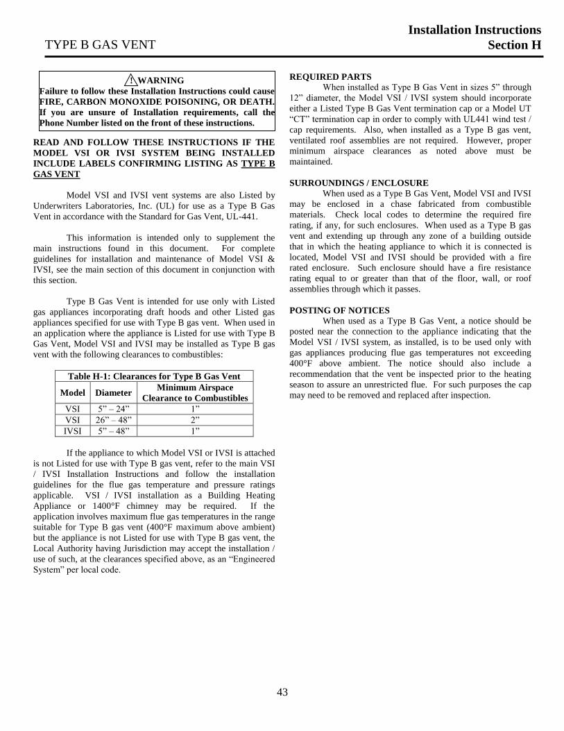
43
READ AND FOLLOW THESE INSTRUCTIONS IF THE
MODEL VSI OR IVSI SYSTEM BEING INSTALLED
INCLUDE LABELS CONFIRMING LISTING AS TYPE B
GAS VENT
Model VSI and IVSI vent systems are also Listed by
Underwriters Laboratories, Inc. (UL) for use as a Type B Gas
Vent in accordance with the Standard for Gas Vent, UL-441.
This information is intended only to supplement the
main instructions found in this document. For complete
guidelines for installation and maintenance of Model VSI &
IVSI, see the main section of this document in conjunction with
this section.
Type B Gas Vent is intended for use only with Listed
gas appliances incorporating draft hoods and other Listed gas
appliances specified for use with Type B gas vent. When used in
an application where the appliance is Listed for use with Type B
Gas Vent, Model VSI and IVSI may be installed as Type B gas
vent with the following clearances to combustibles:
Table H-1: Clearances for Type B Gas Vent
Model Diameter Minimum Airspace
Clearance to Combustibles
VSI 5” – 24” 1”
VSI 26” – 48” 2”
IVSI 5” – 48” 1”
If the appliance to which Model VSI or IVSI is attached
is not Listed for use with Type B gas vent, refer to the main VSI
/ IVSI Installation Instructions and follow the installation
guidelines for the flue gas temperature and pressure ratings
applicable. VSI / IVSI installation as a Building Heating
Appliance or 1400°F chimney may be required. If the
application involves maximum flue gas temperatures in the range
suitable for Type B gas vent (400°F maximum above ambient)
but the appliance is not Listed for use with Type B gas vent, the
Local Authority having Jurisdiction may accept the installation /
use of such, at the clearances specified above, as an “Engineered
System” per local code.
REQUIRED PARTS
When installed as Type B Gas Vent in sizes 5” through
12” diameter, the Model VSI / IVSI system should incorporate
either a Listed Type B Gas Vent termination cap or a Model UT
“CT” termination cap in order to comply with UL441 wind test /
cap requirements. Also, when installed as a Type B gas vent,
ventilated roof assemblies are not required. However, proper
minimum airspace clearances as noted above must be
maintained.
SURROUNDINGS / ENCLOSURE
When used as a Type B Gas Vent, Model VSI and IVSI
may be enclosed in a chase fabricated from combustible
materials. Check local codes to determine the required fire
rating, if any, for such enclosures. When used as a Type B gas
vent and extending up through any zone of a building outside
that in which the heating appliance to which it is connected is
located, Model VSI and IVSI should be provided with a fire
rated enclosure. Such enclosure should have a fire resistance
rating equal to or greater than that of the floor, wall, or roof
assemblies through which it passes.
POSTING OF NOTICES
When used as a Type B Gas Vent, a notice should be
posted near the connection to the appliance indicating that the
Model VSI / IVSI system, as installed, is to be used only with
gas appliances producing flue gas temperatures not exceeding
400°F above ambient. The notice should also include a
recommendation that the vent be inspected prior to the heating
season to assure an unrestricted flue. For such purposes the cap
may need to be removed and replaced after inspection.
! WARNING
Failure to follow these Installation Instructions could cause
FIRE, CARBON MONOXIDE POISONING, OR DEATH.
If you are unsure of Installation requirements, call the
Phone Number listed on the front of these instructions.
TYPE B GAS VENT
Installation Instructions
Section H
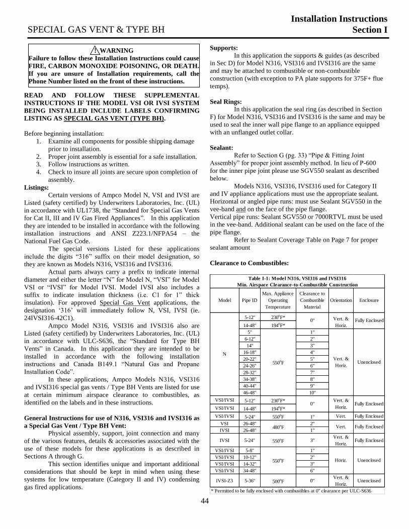
44
READ AND FOLLOW THESE SUPPLEMENTAL
INSTRUCTIONS IF THE MODEL VSI OR IVSI SYSTEM
BEING INSTALLED INCLUDE LABELS CONFIRMING
LISTING AS SPECIAL GAS VENT (TYPE BH).
Before beginning installation:
1. Examine all components for possible shipping damage
prior to installation.
2. Proper joint assembly is essential for a safe installation.
3. Follow instructions as written.
4. Check to insure all joints are secure upon completion of
assembly.
Listings:
Certain versions of Ampco Model N, VSI and IVSI are
Listed (safety certified) by Underwriters Laboratories, Inc. (UL)
in accordance with UL1738, the “Standard for Special Gas Vents
for Cat II, III and IV Gas Fired Appliances”. In this application
they are intended to be installed in accordance with the following
installation instructions and ANSI Z223.1/NFPA54 – the
National Fuel Gas Code.
The special versions Listed for these applications
include the digits “316” suffix on their model designation, so
they are known as Models N316, VSI316 and IVSI316.
Actual parts always carry a prefix to indicate internal
diameter and either the letter “N” for Model N, “VSI” for Model
VSI or “IVSI” for Model IVSI. Model IVSI also includes a
suffix to indicate insulation thickness (i.e. C1 for 1” thick
insulation). For approved Special Gas Vent applications, the
designation ‘316’ will immediately follow N, VSI, IVSI (ie.
24IVSI316-42C1).
Ampco Model N316, VSI316 and IVSI316 also are
Listed (safety certified) by Underwriters Laboratories, Inc. (UL)
in accordance with ULC-S636, the “Standard for Type BH
Vents” in Canada. In this application they are intended to be
installed in accordance with the following installation
instructions and Canada B149.1 “Natural Gas and Propane
Installation Code”.
In these applications, Ampco Models N316, VSI316
and IVSI316 special gas vents / Type BH Vents are listed for use
at certain minimum airspace clearance to combustibles, as
identified on the labels and in these instructions.
General Instructions for use of N316, VSI316 and IVSI316 as
a Special Gas Vent / Type BH Vent:
Physical assembly, support, joint connection and many
of the various features, details & accessories associated with the
use of these models for these applications is as described in
Sections A through G.
This section identifies unique and important additional
considerations that should be kept in mind when using these
systems for low temperature (Category II and IV) condensing
gas fired applications.
Supports:
In this application the supports & guides (as described
in Sec D) for Model N316, VSI316 and IVSI316 are the same
and may be attached to combustible or non-combustible
construction (with exception to PA plate supports for 375F+ flue
temps).
Seal Rings:
In this application the seal ring (as described in Section
F) for Model N316, VSI316 and IVSI316 is the same and may be
used to seal the inner wall pipe flange to an appliance equipped
with an unflanged outlet collar.
Sealant:
Refer to Section G (pg. 33) “Pipe & Fitting Joint
Assembly” for proper joint assembly method. In lieu of P-600
for the inner pipe joint please use SGV550 sealant as described
below.
Models N316, VSI316, IVSI316 used for Category II
and IV appliance applications must use the appropriate sealant.
Horizontal or angled pipe runs: must use Sealant SGV550 in the
vee-band and on the face of the pipe flange.
Vertical pipe runs: Sealant SGV550 or 7000RTVL must be used
in the vee-band. Additional sealant can be used on the face of the
pipe flange.
Refer to Sealant Coverage Table on Page 7 for proper
sealant amount
Clearance to Combustibles:
Model Pipe ID
Max. Appliance
Operating
Temperature
Clearance to
Combustible
Material
Orientation Enclosure
5-12" 230oF*
14-48" 194oF*
5" 1"
6-12" 2"
14" 3"
16-18" 4"
20-22" 5"
24-26" 6"
28-32" 7"
34-38" 8"
40-44" 9"
46-48" 10"
VSI/IVSI 5-12" 230oF*
VSI/IVSI 14-48" 194oF*
VSI/IVSI 5-24" 550oF 1" Vert. Fully Enclosed
VSI 26-48" 2"
IVSI 26-48" 1"
IVSI 5-24" 550oF 3"
Vert. &
Horiz.Fully Enclosed
VSI/IVSI 5-8" 1"
VSI/IVSI 10-12" 2"
VSI/IVSI 14-32" 3"
VSI/IVSI 34-48" 6"
IVSI-Z3 5-36" 500oF 0"
Vert. &
Horiz.Unenclosed
* Permitted to be fully enclosed with combustibles at 0" clearance per ULC-S636
550oF Horiz. Unenclosed
0"Vert. &
Horiz.Fully Enclosed
480oF Vert. Fully Enclosed
Table I-1: Model N316, VSI316 and IVSI316
Min. Airspace Clearance-to-Combustible Construction
N
0" Vert. &
Horiz.Fully Enclosed
550oF
Vert. &
Horiz.Unenclosed
! WARNING
Failure to follow these Installation Instructions could cause
FIRE, CARBON MONOXIDE POISONING, OR DEATH.
If you are unsure of Installation requirements, call the
Phone Number listed on the front of these instructions.
SPECIAL GAS VENT & TYPE BH
Installation Instructions
Section I
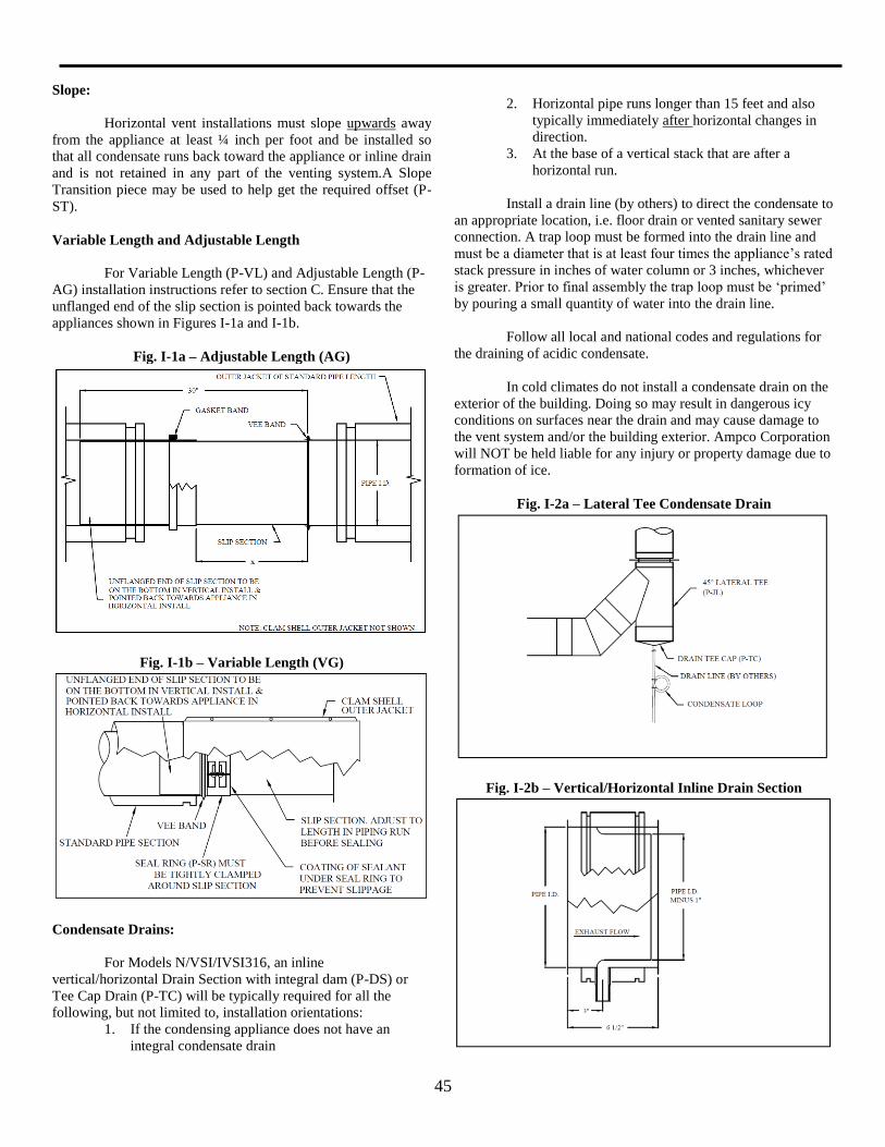
45
Slope:
Horizontal vent installations must slope upwards away
from the appliance at least ¼ inch per foot and be installed so
that all condensate runs back toward the appliance or inline drain
and is not retained in any part of the venting system.A Slope
Transition piece may be used to help get the required offset (P-
ST).
Variable Length and Adjustable Length
For Variable Length (P-VL) and Adjustable Length (P-
AG) installation instructions refer to section C. Ensure that the
unflanged end of the slip section is pointed back towards the
appliances shown in Figures I-1a and I-1b.
Fig. I-1a – Adjustable Length (AG)
Fig. I-1b – Variable Length (VG)
Condensate Drains:
For Models N/VSI/IVSI316, an inline
vertical/horizontal Drain Section with integral dam (P-DS) or
Tee Cap Drain (P-TC) will be typically required for all the
following, but not limited to, installation orientations:
1. If the condensing appliance does not have an
integral condensate drain
2. Horizontal pipe runs longer than 15 feet and also
typically immediately after horizontal changes in
direction.
3. At the base of a vertical stack that are after a
horizontal run.
Install a drain line (by others) to direct the condensate to
an appropriate location, i.e. floor drain or vented sanitary sewer
connection. A trap loop must be formed into the drain line and
must be a diameter that is at least four times the appliance’s rated
stack pressure in inches of water column or 3 inches, whichever
is greater. Prior to final assembly the trap loop must be ‘primed’
by pouring a small quantity of water into the drain line.
Follow all local and national codes and regulations for
the draining of acidic condensate.
In cold climates do not install a condensate drain on the
exterior of the building. Doing so may result in dangerous icy
conditions on surfaces near the drain and may cause damage to
the vent system and/or the building exterior. Ampco Corporation
will NOT be held liable for any injury or property damage due to
formation of ice.
Fig. I-2a – Lateral Tee Condensate Drain
Fig. I-2b – Vertical/Horizontal Inline Drain Section
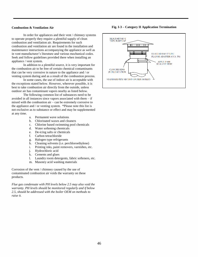
46
Combustion & Ventilation Air
In order for appliances and their vent / chimney systems
to operate properly they require a plentiful supply of clean
combustion and ventilation air. Requirements for such
combustion and ventilation air are found in the installation and
maintenance instructions accompanying the appliance as well as
in vent manufacturer’s literature and various mechanical codes.
Seek and follow guidelines provided there when installing an
appliance / vent system.
In addition to a plentiful source, it is very important for
the combustion air to be free of certain chemical contaminants
that can be very corrosive in nature to the appliance and / or
venting system during and as a result of the combustion process.
In some cases, the use of indoor air is acceptable with
the exceptions stated below. However, wherever possible, it is
best to take combustion air directly from the outside, unless
outdoor air has contaminant vapors nearby as listed below.
The following common list of substances need to be
avoided in all instances since vapors associated with them – if
mixed with the combustion air – can be extremely corrosive to
the appliance and / or venting system. *Please note this list is
not exclusive as to substance or effect and may be supplemented
at any time.
a. Permanent wave solutions
b. Chlorinated waxes and cleaners
c. Chlorine based swimming pool chemicals
d. Water softening chemicals
e. De-icing salts or chemicals
f. Carbon tetrachloride
g. Halogen type refrigerants
h. Cleaning solvents (i.e. perchloroethylene)
i. Printing inks, paint removers, varnishes, etc.
j. Hydrochloric acid
k. Cements and glues
l. Laundry room detergents, fabric softeners, etc.
m. Masonry acid washing materials
Corrosion of the vent / chimney caused by the use of
contaminated combustion air voids the warranty on these
products.
Flue gas condensate with PH levels below 2.5 may also void the
warranty. PH levels should be monitored regularly and if below
2.5, should be addressed with the boiler OEM on methods to
raise it.
Fig. I-3 – Category II Application Termination
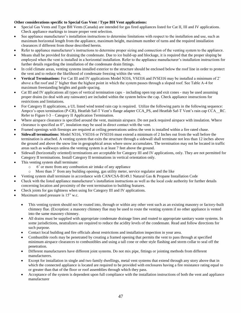
47
Other considerations specific to Special Gas Vent / Type BH Vent applications:
Special Gas Vents and Type BH Vents (Canada) are intended for gas fired appliances listed for Cat II, III and IV applications.
Check appliance markings to insure proper vent selection.
See appliance manufacturer’s installation instructions to determine limitations with respect to the installation and use, such as
maximum horizontal length from the appliance, maximum height, maximum number of turns and the required installation
clearances if different from those described herein.
Refer to appliance manufacturer’s instructions to determine proper sizing and connection of the venting system to the appliance.
Means shall be provided for draining the condensate. Due to ice build-up and blockage, it is required that the proper sloping be
employed when the vent is installed in a horizontal installation. Refer to the appliance manufacturer’s installation instructions for
further details regarding the installation of the condensate drain fittings.
In cold climate areas, venting systems installed exterior to the structure should be enclosed below the roof line in order to protect
the vent and to reduce the likelihood of condensate freezing within the vent.
Vertical Terminations: For Cat III and IV applications Model N316, VSI316 and IVSI316 may be installed a minimum of 2’
above a flat roof and 2’ higher than the highest point in which the system passes through a sloped roof. See Table A-4 for
maximum freestanding heights and guide spacing.
Cat III and IV applications all types of vertical termination caps – including open top and exit cones - may be used assuming
proper drains (to deal with any rainwater) are included within the system below the cap. Check appliance instructions for
restrictions and limitations.
For Category II applications, a UL listed wind tested rain cap is required. Utilize the following parts in the following sequence:
Ampco’s open termination (P-CR), Heatfab Saf-T Vent’s flange adapter CCA_PS, and Heatfab Saf-T Vent’s rain cap CCA__RC.
Refer to Figure I-3 – Category II Application Termination.
Where airspace clearance is specified around the vent, maintain airspace. Do not pack required airspace with insulation. Where
clearance is specified as 0”, insulation may be used in direct contact with the vent.
Framed openings with firestops are required at ceiling penetrations unless the vent is installed within a fire rated chase.
Sidewall terminations: Model N316, VSI316 or IVSI316 must extend a minimum of 2 Inches out from the wall before the
termination is attached. A venting system that exits the structure through a sidewall shall terminate not less than 12 inches above
the ground and above the snow line in geographical areas where snow accumulates. The termination may not be located in traffic
areas such as walkways unless the venting system is at least 7 feet above the ground.
Sidewall (horizontally oriented) terminations are acceptable for Category III and IV applications, only. They are not permitted for
Category II terminations. Install Category II terminations in vertical orientation only.
This venting system shall terminate:
o 6’ or more from any combustion air intake of any appliance
o More than 3’ from any building opening, gas utility meter, service regulator and the like
Venting system shall terminate in accordance with CAN/CSA-B149.1 Natural Gas & Propane Installation Code
Check with the listed appliance manufacturer’s installation instructions as well as the local code authority for further details
concerning location and proximity of the vent termination to building features.
Check joints for gas tightness when using for Category III and IV applications.
Maximum rated pressure is 15” w.c.
This venting system should not be routed into, through or within any other vent such as an existing masonry or factory-built
chimney flue. (Exception: a masonry chimney flue may be used to route the venting system if no other appliance is vented
into the same masonry chimney.
All drains must be supplied with appropriate condensate drainage lines and routed to appropriate sanitary waste systems. In
some jurisdictions, neutralizers are required to reduce the acidity levels of the condensate. Read and follow directions for
such purpose.
Contact local building and fire officials about restrictions and installation inspection in your area.
Combustible roofs may be penetrated by creating a framed opening that permits the vent to pass through at specified
minimum airspace clearances to combustibles and using a tall cone or other style flashing and storm collar to seal off the
penetration.
Different manufacturers have different joint systems. Do not mix pipe, fittings or jointing methods from different
manufacturers.
Except for installation in single and two family dwellings, metal vent systems that extend through any story above that in
which the connected appliance is located are required to be provided with enclosures having a fire resistance rating equal to
or greater than that of the floor or roof assemblies through which they pass.
Acceptance of the system is dependent upon full compliance with the installation instructions of both the vent and appliance
manufacturer
48
Ampco Commercial/Industrial representatives throughout North America
are qualified to provide field service to assist contractors, builders, engineers and
architects in designing Boiler Stacks and Breechings, Grease Ducts, Diesel and
Turbine Exhausts, Freestanding Stack Systems, and Residential Chimney and
Gas Vent Systems. Contact the Ampco Regional Office nearest you for
assistance.
Commercial/Industrial Venting Products Sales Office
Ampco
5030 Corporate Exchange Blvd
Grand Rapids, MI 49512
Tel: 800.669.3269
Fax: 800.972.1421
Ampco Canada
375 Green Rd
Stoney Creek, ON L8E4A5
Tel: 888.735.5475
www.ampcostacks.com
PN: 0015025A Revised: 5/17 2017 Ampco is a registered trademark of Johnson Controls, Inc. in the United States and other countries.