model m3452 - bonitron solutions for ac drives · model m3452 heavy duty braking transistor...
TRANSCRIPT

Web: www.bonitron.com Tel: 615-244-2825 Email: [email protected]
Model M3452 Heavy Duty Braking Transistor
Includes information on the B7, K3, K6, and K9 Chassis
and the A and R5 Board Options
Customer Reference Manual

Bonitron, Inc.
2
Bonitron, Inc. Nashville, TN
An Industry Leader in AC Drive Systems and Industrial Electronics
ABOUT BONITRON Bonitron designs and manufactures quality industrial electronics that improve the reliability of processes and variable frequency drives worldwide. With products in numerous industries, and an educated and experienced team of engineers, Bonitron has seen thousands of products engineered since 1962 and welcomes custom applications.
With engineering, production, and testing all in the same facility, Bonitron is able to ensure its products are of the utmost quality and ready to be applied to your application.
The Bonitron engineering team has the background and expertise necessary to design, develop, and manufacture the quality industrial electronic systems demanded in today’s market. A strong academic background supported by continuing education is complemented by many years of hands-on field experience. A clear advantage Bonitron has over many competitors is combined on-site engineering labs and manufacturing facilities, which allows the engineering team to have immediate access to testing and manufacturing. This not only saves time during prototype development, but also is essential to providing only the highest quality products.
The sales and marketing teams work closely with engineering to provide up-to-date information and provide remarkable customer support to make sure you receive the best solution for your application. Thanks to this combination of quality products and superior customer support, Bonitron has products installed in critical applications worldwide.

Bonitron, Inc.
3
AC DRIVE OPTIONS In 1975, Bonitron began working with AC inverter drive specialists at synthetic fiber plants to develop speed control systems that could be interfaced with their plant process computers. Ever since, Bonitron has developed AC drive options that solve application issues associated with modern AC variable frequency drives and aid in reducing drive faults. Below is a sampling of Bonitron’s current product offering.
WORLD CLASS PRODUCTS
Undervoltage Solutions
Overvoltage Solutions
Uninterruptible Power for Drives
(DC Bus Ride-Thru)
Voltage Regulators
Chargers and Dischargers
Energy Storage
Braking Transistors
Braking Resistors
Transistor/Resistor Combo
Line Regeneration
Dynamic Braking for Servo Drives
Common Bus Solutions
Portable Maintenance Solutions
Single Phase Power Supplies
3-Phase Power Supplies
Common Bus Diodes
Capacitor Formers
Capacitor Testers
Power Quality Solutions
Green Solutions
12 and 18 Pulse Kits
Line Regeneration

M3452-A and -R5
4
1. INTRODUCTION ............................................................................................................. 7
1.1. Who Should Use ........................................................................................................... 7 1.2. Purpose and Scope ...................................................................................................... 7 1.3. Manual Version and Change Record ............................................................................ 7
Figure 1-1: M3452 in the B7, K6, and K9 Enclosures ............................................................... 7 1.4. Symbol Conventions Used in this Manual and on Equipment ....................................... 8
2. PRODUCT DESCRIPTION ................................................................................................ 9
2.1. Related Products .......................................................................................................... 9 2.2. Part Number Breakdown .............................................................................................. 9
Figure 2-1: M3452 Part Number Breakdown ............................................................................. 9 Table 2-1: Control Voltage Rating ........................................................................................... 10 Table 2-2: Available Braking Current Ratings ......................................................................... 10 Table 2-3: DC Bus Voltage Rating .......................................................................................... 10 Table 2-4: Chassis Codes ....................................................................................................... 11 Table 2-5: Control Option Codes ............................................................................................. 11
2.3. General Specifications ................................................................................................ 11 Table 2-6: General Specifications ........................................................................................... 11
2.4. General Precautions and Safety Warnings ................................................................. 12
3. INSTALLATION INSTRUCTIONS ...................................................................................... 13
3.1. Product Inspection ...................................................................................................... 13 3.2. Site Selection ............................................................................................................. 13 3.3. Mounting..................................................................................................................... 13 3.4. Wiring and Customer Connections ............................................................................. 14
3.4.1. Power Wiring.................................................................................................................. 14 Table 3-1: Power Wiring Specifications ................................................................................... 14
3.4.2. I/O Wiring ....................................................................................................................... 16 Table 3-2: I/O Terminal Block Specifications: for Units 200A and Larger ............................... 16 Table 3-3: I/O Terminal Block Specifications: For Units up to 200A ....................................... 16 Table 3-4: I/O Terminal Block Specifications: R5 Control Board ............................................ 17 Figure 3-1: Customer Connections in B7 Chassis .................................................................. 18 Figure 3-2: Customer Connections in K3 Chassis .................................................................. 18 Figure 3-3: Customer Connections in K6 Chassis .................................................................. 19 Figure 3-4: Customer Connections in K9 Chassis .................................................................. 19
3.5. Typical Configurations ................................................................................................ 20 Figure 3-3: Master Stand-Alone Hookup ................................................................................. 20 Figure 3-4: Master with Slave Hookup .................................................................................... 20 Figure 3-5: Master with Two Slaves Hookup ........................................................................... 20 Figure 3-6: I/O Hookups .......................................................................................................... 21 Figure 3-7: Braking Transistor Customer Connections ........................................................... 23
4. OPERATION ............................................................................................................... 25
4.1. Functional Description ................................................................................................ 25 4.2. Features ..................................................................................................................... 25
4.2.1. Indicators ....................................................................................................................... 25 4.2.2. Terminal Strip I/O ........................................................................................................... 25 4.2.3. Master / Slave Control (200 Amp to 800 Amp) .............................................................. 28
Table 4-1: Jumper Positions .................................................................................................... 28 Figure 4-1: Master/Slave Jumper Layout ................................................................................ 29
4.3. Startup ........................................................................................................................ 29 4.3.1. Pre-Power Checks ......................................................................................................... 29 4.3.2. Startup Procedure and Checks...................................................................................... 30

Table of Contents
5
4.4. Operational Adjustments ............................................................................................ 30
5. MAINTENANCE AND TROUBLESHOOTING ...................................................................... 31
5.1. Periodic Testing .......................................................................................................... 31 5.2. Maintenance Items ..................................................................................................... 31 5.3. Troubleshooting .......................................................................................................... 31
5.3.1. Green Control Power light not illuminated ..................................................................... 31 5.3.2. Attached Drive Will Not Precharge ................................................................................ 32 5.3.3. Amber DC Bus light not illuminated ............................................................................... 32 5.3.4. Blown DC bus fuse ........................................................................................................ 32 5.3.5. Fan runs constantly ....................................................................................................... 32 5.3.6. Fan doesn’t run .............................................................................................................. 32 5.3.7. Status contacts won’t close – R2 with Option A ............................................................ 33 5.3.8. Status contacts won’t close – R5 Option ....................................................................... 33 5.3.9. Module over-temp, or module seems too hot ................................................................ 34 5.3.10. Drive trips on overvoltage .............................................................................................. 34 5.3.11. Red Braking light flickers ............................................................................................... 35 5.3.12. Red Braking light stays on all the time .......................................................................... 35 5.3.13. Slave Units do not follow the Master ............................................................................. 35
5.4. Technical Help ............................................................................................................ 36
6. ENGINEERING DATA ................................................................................................... 37
6.1. Ratings Charts ............................................................................................................ 37 Table 6-1: Module Ratings: 230 – 240 VAC Drives (375 VDC Setpoint) ................................ 37 Table 6-2: Module Ratings: 380 – 415 VAC Drives (620 VDC Setpoint) ................................ 38 Table 6-3: Module Ratings: 460 – 480 VAC Drives (750 VDC Setpoint) ................................ 39 Table 6-4: Module Ratings: 575 – 600 VAC Drives (940 VDC Setpoint) ................................ 40 Table 6-5: Module Ratings: 690VAC Drives (1090 VDC Setpoint) ......................................... 41
6.2. Watt loss..................................................................................................................... 41 Table 6-6: Watt Loss ............................................................................................................... 41
6.3. Certifications ............................................................................................................... 41 6.4. UL 508A Short Circuit Current Rating ......................................................................... 41 6.5. Fuse/Circuit Breaker Sizing and Rating ...................................................................... 41 6.6. DC Bus Link Length Limits ......................................................................................... 42
Table 6-7: Maximum Inductance for DC Link Cable ............................................................... 42 Figure 6-1: DC Link ................................................................................................................. 42
6.7. Resistor Link Length Limits ......................................................................................... 42 6.8. Dimensions and Mechanical Drawings ....................................................................... 43
Figure 6-2: M3452 B7 Chassis Dimensional Outline Drawing ................................................ 43 Figure 6-3: M3452 K3 Chassis Dimensional Outline Drawing ................................................ 44 Figure 6-4: M3452 K6 Chassis Dimensional Outline Drawing ................................................ 44 Figure 6-5: M3452 K9 Chassis Dimensional Outline Drawing ................................................ 45
6.9. Block Diagrams .......................................................................................................... 47 Figure 6-6: Block Diagram ....................................................................................................... 47
7. APPENDICES .............................................................................................................. 49
7.1. Application Notes ........................................................................................................ 49 7.1.1. Sizing your braking requirements .................................................................................. 49 7.1.3. Common Bus Application Note ...................................................................................... 51 7.1.4. Bonitron Line Regeneration Modules ............................................................................ 52

M3452-A and -R5
6
This page intentionally left blank

User’s Manual
7
1. INTRODUCTION
1.1. WHO SHOULD USE This manual is intended for use by anyone who is responsible for integrating, installing, maintaining, troubleshooting, or using this equipment with any AC drive system.
Please keep this manual for future reference.
1.2. PURPOSE AND SCOPE This manual is a user’s guide for the M3452 heavy duty braking transistor. It will provide the user with the necessary information to successfully install, integrate, and use the M3452 heavy duty braking transistor in a variable frequency AC drive system.
In the event of any conflict between this document and any publication and/or documentation related to the AC drive system, the latter shall have precedence.
1.3. MANUAL VERSION AND CHANGE RECORD In Rev 04a the Model name was changed to heavy duty braking transistor and the new product labels are shown.
Fuse information was updated in Rev 04b.
Indicator light information was updated in Rev 04c.
DC Bus info, connection drawings, ratings tables, and dimensional outlines were updated in Rev 04d.
Certification information was updated in Rev 04e
Link Length limits were updated in Rev 04f.
Master/Slave system was updated for clarity in Rev 04g.
Drawing 110279 was updated in Rev 04h.
Updated Figure 4-1 in Rev 04i.
The manual template was updated in Rev 04j.
Grammatical changes were made in Rev 04k.
Figure 1-1: M3452 in the B7, K6, and K9 Enclosures

M3452-A and -R5
8
1.4. SYMBOL CONVENTIONS USED IN THIS MANUAL AND ON
EQUIPMENT
Earth Ground or Protective Earth
AC Voltage
DC Voltage
DANGER!
Electrical Hazard - Identifies a statement that indicates a shock or electrocution hazard that must be avoided.
DANGER!
DANGER: Identifies information about practices or circumstances that can lead to personal injury or death, property damage, or economic loss.
CAUTION!
CAUTION: Identifies information about practices or circumstances that can lead to property damage, or economic loss. Attentions help you identify a potential hazard, avoid a hazard, and recognize the consequences.
CAUTION!
Heat or burn hazard - Identifies a statement regarding heat production or a burn hazard that should be avoided.
User’s Manual
9
2. PRODUCT DESCRIPTION Bonitron M3452 heavy duty braking transistors are used with AC drives to allow full power braking and eliminate overvoltage faults. This allows controlled braking and dramatically shortens motor stopping time. The M3452 works with variable frequency drives (with DC bus connections) to monitor the DC bus. If overvoltage occurs, the M3452 shunts the excess energy through an external braking resistor to prevent overvoltage faults.
The need for regenerated voltage control occurs in applications where the frequency of an AC motor at times exceeds that of its variable frequency drive. In this case, the motor acts as a generator. The energy generated by the motor must be dissipated as heat or returned to the power line. If this energy is not controlled, the motor may run with high peak voltages, the energy may be dissipated as heat in the motor, or the drive may trip on an over-voltage condition.
2.1. RELATED PRODUCTS
BRAKING TRANSISTORS Like the M3452 heavy duty braking transistors, Bonitron M3575T and
M3675T standard duty braking transistors work with variable frequency drives (with DC bus connections) to monitor the DC bus. If overvoltage occurs, the M3575T or M3675T shunts the excess energy through an external braking resistor to prevent overvoltage faults. The M3575T series is rated up to 600A peak / 20% duty, while the M3675T series is rated up to 10A peak / 20% duty.
BRAKING RESISTORS Bonitron offers resistor solutions to complement its braking transistor
selection. The M3575R series is rated up to 32A peak / 20% duty, while the M3775R series is rated up to 1600A / 100% duty. Custom resistors are also available.
LINE REGENERATION Bonitron is famous for its industry-leading line regeneration solutions.
Bonitron M3645 line regens return regenerative energy back onto the AC line instead of dissipating the energy as heat in a resistor, and are ideal for applications with high duty cycles, frequent deceleration, or where heat from a resistor may be an issue.
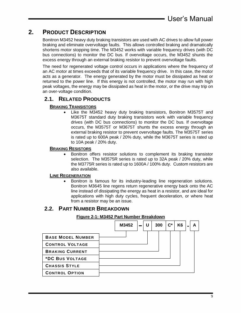
2.2. PART NUMBER BREAKDOWN
Figure 2-1: M3452 Part Number Breakdown
BASE MODEL NUMBER
CONTROL VOLTAGE
BRAKING CURRENT
*DC BUS VOLTAGE
CHASSIS STYLE
CONTROL OPTION
M3452 U 300 C* K6 - A

M3452-A and -R5
10
BASE MODEL NUMBER
The base model number for all heavy duty braking transistors is M3452.
CONTROL VOLTAGE RATING
The control voltage rating indicates the voltage level to be used to supply control power to the unit. Most units utilize the AC line voltage supplied to the drive system. However, this is not required. Other AC voltage sources can be used if desired. Refer to the unit specifications to determine the voltage source. The control voltage is indicated by a code letter.
Table 2-1: Control Voltage Rating
CONTROL VOLTAGE
RATING CODE VOLTAGES
U 115-120VAC
L 230-240VAC
E 380-415VAC
H 460-480VAC
C 575-600VAC
BRAKING CURRENT RATING
The braking current rating indicates the maximum current level that can safely be handled by the M3452 dynamic braking transistor module.
The braking current rating is indicated by a 2 or 3-digit number. For example, 300 would indicate a braking current rating of 300 amps maximum.
All current ratings shown in Table 2-2 are available for voltages shown in Table 2-1.
Table 2-2: Available Braking Current Ratings
AVAILABLE CURRENT RATINGS (ADC)
200, 300, 600, 800, 1200, 1600
*DC BUS VOLTAGE
This code is used only if different from the control voltage rating.
Omit this position if control voltage is the same as nominal AC line voltage.
The DC bus voltage indicates the voltage regulation level of the DC bus if the control voltage input does not correspond to the actual drive bus being controlled.
The DC bus voltage uses the codes L, E, H, C, and Y as previously defined for the control voltage ratings.
Table 2-3: DC Bus Voltage Rating
VOLTAGE
RATING CODE
VOLTAGES (Nominal AC Line / DC Bus Trigger Level)
L 230-240VAC Line / 375VDC
E 380-415VAC Line / 620VDC
H 460-480VAC Line / 750VDC
C 575-600VAC Line / 940VDC
Y 690VAC Line / 1090VDC
Nxxxx(1) Special (xxxxVDC)
(1) Nxxxx is used only for custom trigger levels. Contact Bonitron before specifying Nxxxx.
User’s Manual
11
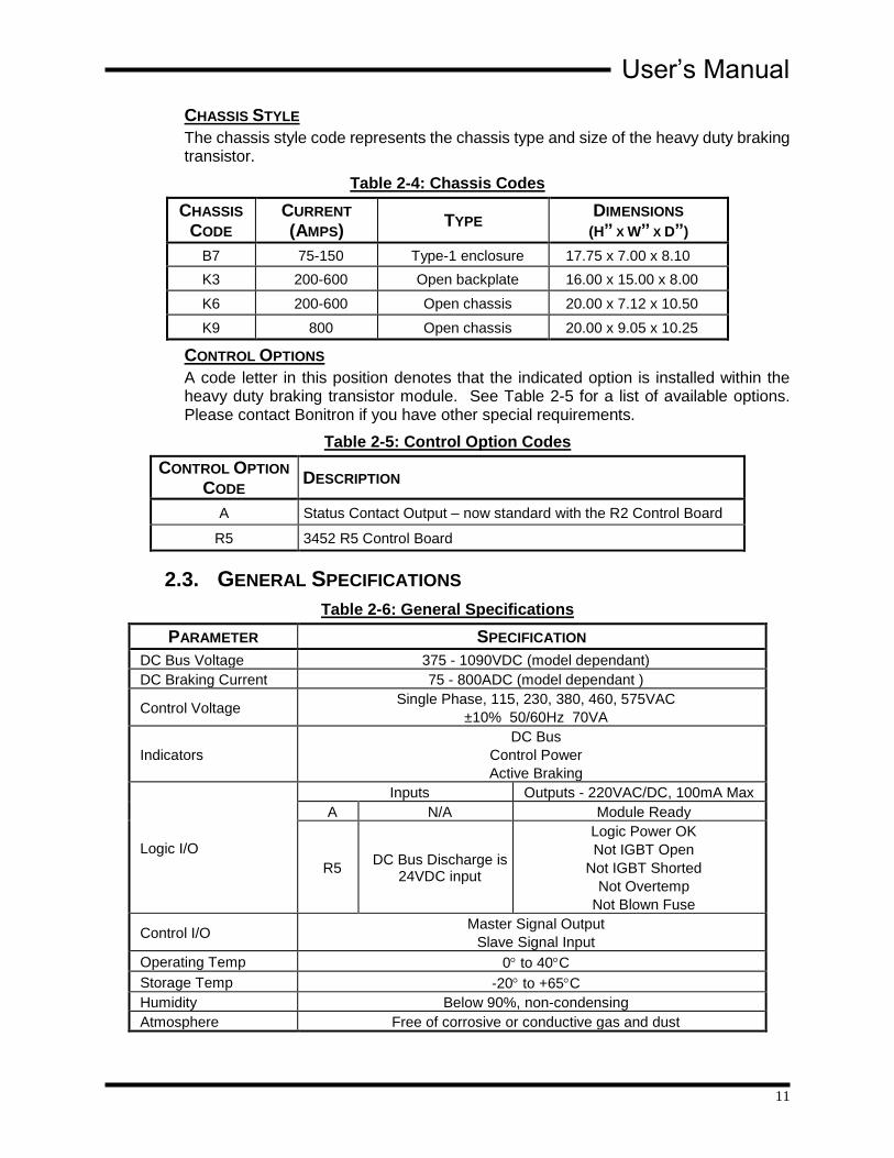
CHASSIS STYLE
The chassis style code represents the chassis type and size of the heavy duty braking transistor.
Table 2-4: Chassis Codes
CHASSIS
CODE CURRENT (AMPS)
TYPE DIMENSIONS
(H” X W” X D”)
B7 75-150 Type-1 enclosure 17.75 x 7.00 x 8.10
K3 200-600 Open backplate 16.00 x 15.00 x 8.00
K6 200-600 Open chassis 20.00 x 7.12 x 10.50
K9 800 Open chassis 20.00 x 9.05 x 10.25
CONTROL OPTIONS
A code letter in this position denotes that the indicated option is installed within the heavy duty braking transistor module. See Table 2-5 for a list of available options. Please contact Bonitron if you have other special requirements.
Table 2-5: Control Option Codes
CONTROL OPTION
CODE DESCRIPTION
A Status Contact Output – now standard with the R2 Control Board
R5 3452 R5 Control Board
2.3. GENERAL SPECIFICATIONS
Table 2-6: General Specifications
PARAMETER SPECIFICATION
DC Bus Voltage 375 - 1090VDC (model dependant)
DC Braking Current 75 - 800ADC (model dependant )
Control Voltage Single Phase, 115, 230, 380, 460, 575VAC
±10% 50/60Hz 70VA
Indicators
DC Bus
Control Power
Active Braking
Logic I/O
Inputs Outputs - 220VAC/DC, 100mA Max
A N/A Module Ready
R5 DC Bus Discharge is
24VDC input
Logic Power OK
Not IGBT Open
Not IGBT Shorted
Not Overtemp
Not Blown Fuse
Control I/O Master Signal Output
Slave Signal Input
Operating Temp 0 to 40C
Storage Temp -20 to +65C
Humidity Below 90%, non-condensing
Atmosphere Free of corrosive or conductive gas and dust

M3452-A and -R5
12
2.4. GENERAL PRECAUTIONS AND SAFETY WARNINGS
DANGER!
HIGH VOLTAGES MAY BE PRESENT!
NEVER ATTEMPT TO SERVICE THIS PRODUCT WITHOUT FIRST
DISCONNECTING FROM THE INCOMING AC POWER AND DC BUS.
ALWAYS ALLOW ADEQUATE TIME FOR RESIDUAL VOLTAGES TO
DRAIN BEFORE ATTEMPTING SERVICE.
FAILURE TO HEED THESE WARNINGS MAY RESULT IN
SERIOUS BODILY INJURY OR DEATH.
CAUTION!
THIS PRODUCT WILL GENERATE HIGH AMBIENT TEMPERATURES
DURING OPERATION.
ALWAYS ALLOW AMPLE TIME FOR THE UNIT TO COOL BEFORE
ATTEMPTING SERVICE ON THIS PRODUCT.
BEFORE ATTEMPTING INSTALLATION OR REMOVAL OF THIS
PRODUCT, BE SURE TO REVIEW ALL AC DRIVE DOCUMENTATION
FOR PERTINENT SAFETY PRECAUTIONS.
INSTALLATION AND/OR REMOVAL OF THIS PRODUCT SHOULD ONLY
BE ACCOMPLISHED BY A QUALIFIED ELECTRICIAN IN ACCORDANCE
WITH NATIONAL ELECTRICAL CODE OR EQUIVALENT
REGULATIONS.
ALWAYS BE SURE THE BONITRON EQUIPMENT, IN COORDINATION
WITH ITS NECESSARY LOAD BANK, DOES NOT IN ANY WAY EXCEED
THE CAPACITY OF THE EQUIPMENT TO WHICH IT IS TO BE
CONNECTED!
PRIOR TO USING THIS EQUIPMENT WITH COMMON DC BUS SYSTEMS, REVIEW THE APPLICATION NOTE ON THIS TOPIC FOUND IN SECTION
7 OF THIS MANUAL.
ATTENTION!
Important notice about drives with DC link chokes!
DURING BRAKING SITUATIONS, ENERGY STORED IN A DRIVE’S DC
LINK CHOKES CAN CREATE EXTREME OVER-VOLTAGE CONDITIONS
FOR BRAKING TRANSISTOR MODULES. TO AVOID THESE
CONDITIONS, DC CONNECTIONS FROM THE BRAKING TRANSISTOR
MODULES TO THE DRIVE SYSTEM SHOULD ALWAYS BE MADE
DIRECTLY IN PARALLEL WITH THE DRIVE’S FILTER CAPACITORS. THESE MODULES SHOULD NEVER BE CONNECTED IN SERIES WITH
A DRIVE’S DC LINK CHOKES.
BE SURE TO REVIEW ALL PERTINENT AC DRIVE DOCUMENTATION
TO ENSURE THAT THE PROPER CONNECTIONS ARE USED.
CONTACT THE DRIVE MANUFACTURER OR EQUIPMENT SUPPLIER
FOR ASSISTANCE WITH DRIVE CONNECTIONS.
ANY QUESTIONS AS TO APPLICATION, INSTALLATION, OR SERVICE
SAFETY SHOULD BE DIRECTED TO THE EQUIPMENT SUPPLIER.

User’s Manual
13
3. INSTALLATION INSTRUCTIONS
DANGER!
Installation and/or removal of this product should only be performed by a qualified electrician in accordance with National Electrical Code or local codes and regulations.
Proper installation of the model M3452 dynamic brake module should be accomplished following the steps outlined below. Be sure to refer to all other pertinent system documentation as these steps are performed. Please direct all installation inquiries that may arise during the installation and startup of this product to the equipment supplier or system integrator.
3.1. PRODUCT INSPECTION
Upon receipt of this product, please verify that the product received matches the product that was ordered and that there is no obvious physical damage to the unit. If the wrong product was received or the product is damaged in any way, please contact the supplier from which the product was purchased.
Note: all M3452’s that are rated at or above 200A are preset in the factory to the slave setting. If using the unit as a standalone or multi-unit operation refer to section 4.2.3.
3.2. SITE SELECTION The installation site for the module should be chosen with several considerations in mind:
All units require adequate protection from the elements.
Adequate clearance should be allowed for easy access to terminals and adjustments. This will facilitate inspection and maintenance.
Sufficient circulation of clean, dry air should be provided. Ambient temperatures should not exceed +40°C (+104°F) nor be less than 0°C (+32°F) and non-condensing. Ambient air should not be contaminated with harmful chemical vapors or excessive dust, dirt, or moisture.
The unit will require a minimum clearance of six (6) inches above and below it to allow for proper airflow for cooling. Avoid mounting the unit with its air intake near heat sources.
3.3. MOUNTING Once the installation site has been selected as outlined above, and the mounting holes drilled and mounting studs or anchors installed, the dynamic brake module is ready to be hung in position. Be sure all mounting hardware is tightened securely.
Refer to Section 6.7 of this manual to determine the correct mounting dimensions and provisions for the unit.

M3452-A and -R5
14
3.4. WIRING AND CUSTOMER CONNECTIONS
3.4.1. POWER WIRING
DANGER!
Only qualified electricians should perform and maintain the interconnection wiring of this product. All wiring should be done in accordance with National Electrical Code or equivalent regulations.
Wire size should be selected in accordance with local codes, according to the current rating of the braking transistor. Use copper conductors rated 75°C. In general, the wire type should be selected by the nominal system AC voltage and the current rating of the module.
Table 3-1: Power Wiring Specifications
CHASSIS TERMINAL CONNECTION TORQUE
K3 DC+, RES+ 3/8” stud 192 lb-in
DC-, RES- 3/8” stud 150 lb-in
K6 DC+, DC-, RES+, RES- 3/8” stud 192 lb-in
K9 DC+, DC-, RES+, RES- 1/2" stud 360 lb-in
B7 DC+, DC-, RES, RES 1/4" stud 61 lb-in
3.4.1.1. DC BUS CONNECTION
As a rule, 30 feet (10m) is the maximum total buswork or cable that the chopper can be mounted from the drive. The preferred installation distance is 15 feet (5m), as the cable must go out and back. If you must connect the choppers farther away, see Section 6.6.
The braking transistor must be connected directly to the DC bus filter capacitors of the drive.
Figure 3-5 is an example of the terminals that may be available in your installation. Not all of the terminals may be on your drive. Refer to the drive manufacturer's manual or technical documents to locate the proper terminals. Your drive will have different terminal markings depending on manufacturer and drive series.
Ensure that the polarity of the connection is correct. Incorrect polarity will effectively short the DC bus of the drive, and can cause severe damage to the drive, load resistor, and the Bonitron braking transistor.
The proper terminals to attach the braking transistor are marked + and - on Figure 3-5.
The terminals marked BR+ and BR- are intended for the internal braking transistor. If the Bonitron external braking transistor is hooked to the terminals, the braking transistor will not operate properly. In some cases, it may cause drive failure.
The terminals marked X and Y are intended for connection of a DC link choke. If the Bonitron braking transistor is connected to the terminals marked "X" and "-" in Figure 3-5, switching resonances caused by the DC link choke will destroy the braking transistor. If the Bonitron braking transistor is connected between X and Y, the drive will not operate.
User’s Manual
15
If the braking transistor is connected to the terminals marked "A" and "B" in Figure 3-5, switching resonances caused by the lack of filter capacitance during precharge will destroy the braking transistor.
3.4.1.2. RESISTOR CONNECTION
The polarity of the resistor connections is not critical; however, it is critical that the resistor be connected to the proper terminals. Improper hookup can lead to the resistor being connected directly across the DC bus, which will cause severe overheating and drive stress.
3.4.1.3. GROUNDING REQUIREMENTS
All units come equipped with either a ground terminal or ground stud that is connected to the module chassis. Ground the chassis in accordance with local codes. Typically, the wire gauge will be the same as is used to ground the attached drive.

M3452-A and -R5
16
3.4.2. I/O WIRING
Table 3-2: I/O Terminal Block Specifications: for Units 200A and Larger
TERMINAL FUNCTION ELECTRICAL
SPECIFICATIONS MIN WIRE
AWG MAX WIRE
AWG TORQUE
LB-IN
TS1-1 Control Voltage
L1
120V – 0.6A
230V – 0.3A
460V – 0.16A
575V – 0.15A
16 12 5.3 lb-in
TS1-2 Control Voltage
L2
120V – 0.6A
230V – 0.3A
460V – 0.16A
575V – 0.15A
16 12 5.3 lb-in
TS1-3 Control Voltage
Gnd 16 12 5.3 lb-in
TS1-4 Master Output + Analog Signal 16 12 5.3 lb-in
TS1-5 Master Output + Analog Signal 16 12 5.3 lb-in
TS1-6 Master Output - Analog Signal 16 12 5.3 lb-in
TS1-7 Master Output - Analog Signal 16 12 5.3 lb-in
TS1-8 Slave Input + Analog Signal 16 12 5.3 lb-in
TS1-9 Slave Input - Analog Signal 16 12 5.3 lb-in
TS1-10 [1] Ready Status NC 220VAC/DC, 100mA Max [2] 16 12 5.3 lb-in
TS1-11 [1] Ready Status COM 220VAC/DC, 100mA Max [2] 16 16 5.3 lb-in
TS1-12 [1] Ready Status NO 220VAC/DC, 100mA Max [2] 16 16 5.3 lb-in
Table 3-3: I/O Terminal Block Specifications: For Units up to 200A
TERMINAL FUNCTION ELECTRICAL
SPECIFICATIONS MIN WIRE
AWG MAX WIRE
AWG TORQUE
LB-IN
TS1-1 Control Voltage
L1
120V – 0.6A
230V – 0.3A
460V – 0.16A
575V – 0.15A
16 12 5.3 lb-in
TS1-2 Control Voltage
L2
120V – 0.6A
230V – 0.3A
460V – 0.16A
575V – 0.15A
16 12 5.3 lb-in
TS1-3 Control Voltage
Gnd 16 12 5.3 lb-in
TS1-4 [1] Ready Status NC 220VAC/DC, 100mA Max [2] 16 12 5.3 lb-in
TS1-5 [1] Ready Status COM 220VAC/DC, 100mA Max [2] 16 16 5.3 lb-in
TS1-6 [1] Ready Status NO 220VAC/DC, 100mA Max [2] 16 16 5.3 lb-in
[1] These terminals come standard with the “A” option.
[2] Solid State relay output.
User’s Manual
17
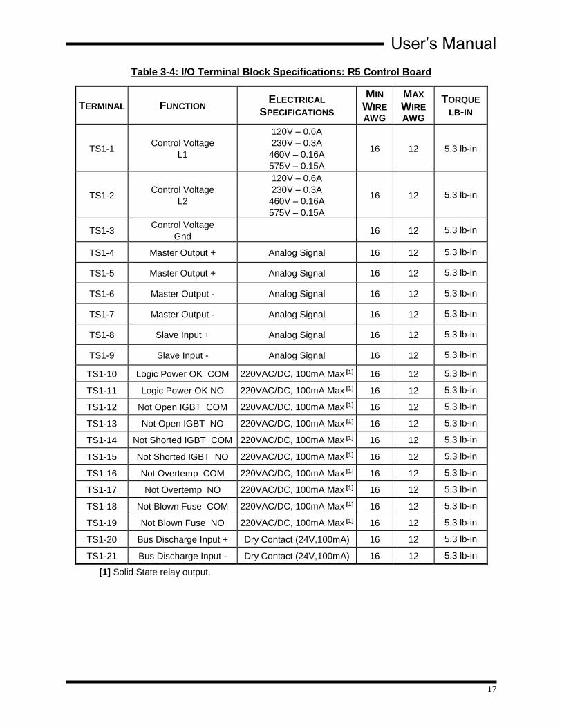
Table 3-4: I/O Terminal Block Specifications: R5 Control Board
TERMINAL FUNCTION ELECTRICAL
SPECIFICATIONS
MIN
WIRE
AWG
MAX
WIRE
AWG
TORQUE LB-IN
TS1-1 Control Voltage
L1
120V – 0.6A
230V – 0.3A
460V – 0.16A
575V – 0.15A
16 12 5.3 lb-in
TS1-2 Control Voltage
L2
120V – 0.6A
230V – 0.3A
460V – 0.16A
575V – 0.15A
16 12 5.3 lb-in
TS1-3 Control Voltage
Gnd 16 12 5.3 lb-in
TS1-4 Master Output + Analog Signal 16 12 5.3 lb-in
TS1-5 Master Output + Analog Signal 16 12 5.3 lb-in
TS1-6 Master Output - Analog Signal 16 12 5.3 lb-in
TS1-7 Master Output - Analog Signal 16 12 5.3 lb-in
TS1-8 Slave Input + Analog Signal 16 12 5.3 lb-in
TS1-9 Slave Input - Analog Signal 16 12 5.3 lb-in
TS1-10 Logic Power OK COM 220VAC/DC, 100mA Max [1] 16 12 5.3 lb-in
TS1-11 Logic Power OK NO 220VAC/DC, 100mA Max [1] 16 12 5.3 lb-in
TS1-12 Not Open IGBT COM 220VAC/DC, 100mA Max [1] 16 12 5.3 lb-in
TS1-13 Not Open IGBT NO 220VAC/DC, 100mA Max [1] 16 12 5.3 lb-in
TS1-14 Not Shorted IGBT COM 220VAC/DC, 100mA Max [1] 16 12 5.3 lb-in
TS1-15 Not Shorted IGBT NO 220VAC/DC, 100mA Max [1] 16 12 5.3 lb-in
TS1-16 Not Overtemp COM 220VAC/DC, 100mA Max [1] 16 12 5.3 lb-in
TS1-17 Not Overtemp NO 220VAC/DC, 100mA Max [1] 16 12 5.3 lb-in
TS1-18 Not Blown Fuse COM 220VAC/DC, 100mA Max [1] 16 12 5.3 lb-in
TS1-19 Not Blown Fuse NO 220VAC/DC, 100mA Max [1] 16 12 5.3 lb-in
TS1-20 Bus Discharge Input + Dry Contact (24V,100mA) 16 12 5.3 lb-in
TS1-21 Bus Discharge Input - Dry Contact (24V,100mA) 16 12 5.3 lb-in
[1] Solid State relay output.

M3452-A and -R5
18
Figure 3-1: Customer Connections in B7 Chassis
Figure 3-2: Customer Connections in K3 Chassis
Dwgs: 120265 and 120267 Rev: 20120726
User’s Manual
19
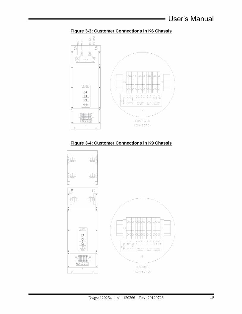
Figure 3-3: Customer Connections in K6 Chassis
Figure 3-4: Customer Connections in K9 Chassis
Dwgs: 120264 and 120266 Rev: 20120726
M3452-A and -R5
20
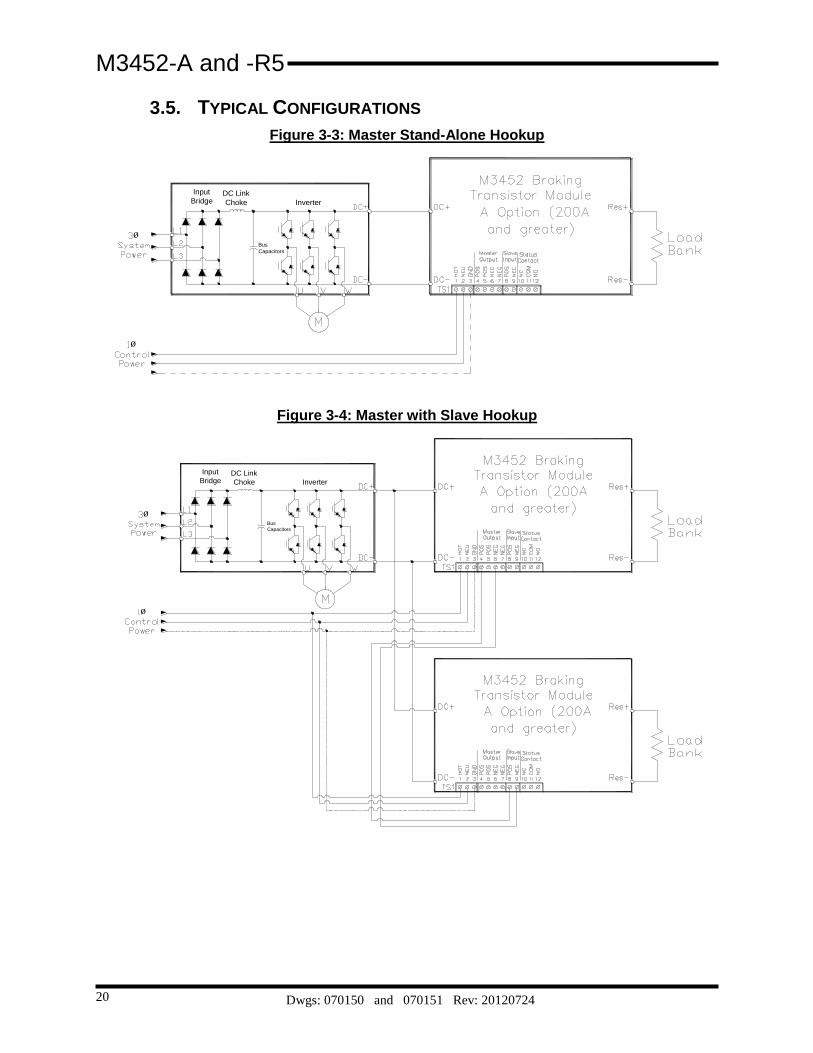
3.5. TYPICAL CONFIGURATIONS
Figure 3-3: Master Stand-Alone Hookup
ø
DC Link
Choke
Input
Bridge
Bus
Capacitors
Inverter
ø
Figure 3-4: Master with Slave Hookup
ø
DC Link
Choke
Input
Bridge
Bus
Capacitors
Inverter
ø
Dwgs: 070150 and 070151 Rev: 20120724

User’s Manual
21
Figure 3-5: Master with Two Slaves Hookup
DC Link
Choke
Bus
Capacitors
Inverter
ø
ø
Input
Bridge
Dwg: 070152 Rev: 20120724

M3452-A and -R5
22
Figure 3-6: I/O Hookups
R2- A CONNECTIONS FOR 200A – 800A MODULES
R2- A CONNECTIONS FOR MODULES LESS THAN 200A
R5 CONNECTIONS FOR ALL MODULES
Dwg: 070153 Rev: 20120724

User’s Manual
23
Figure 3-7: Braking Transistor Customer Connections
MO
TO
R
Inp
ut
Re
ctifie
r
ØA
ØB
ØC
Pre
ch
arg
e (
3)
+X
Y
DC
Lin
k C
ho
ke
(2)
BR
+B
R-
Inte
rna
l B
rake
Tra
nsis
tor
co
nn
ectio
n
(No
t U
sed
)
-
Lo
ad
Ban
k
Re
sis
tor
Bo
nitro
n B
rakin
g
Tra
nsis
tor
DC
+
RE
S
DC
-
RE
S
No
tes:
(1)
Fu
se
no
t in
clu
de
d in
16
00
am
p M
14
ch
assis
bra
kin
g tra
nsis
tor
(2)
Pre
ch
arg
e c
on
ne
ctio
ns m
ay n
ot b
e e
xte
rna
l
(3)
Ch
oke
ma
y b
e in
tern
al to
drive
AB
(1)
DC
Bu
s F
ilte
r
Ca
pa
cito
rs
Ou
tpu
t
Inve
rte
r
Dwg: 110279 Rev: 20130313

M3452-A and -R5
24
This page intentionally left blank

User’s Manual
25
4. OPERATION
4.1. FUNCTIONAL DESCRIPTION The M3452 heavy duty braking transistor controls the bus voltage of a variable frequency drive by transferring energy to a resistor.
When the drive’s DC bus voltage exceeds a fixed setpoint, the M3452’s control electronics turn on an IGBT transistor connecting a resistive load across the DC bus. When the DC bus drops below another threshold, the IGBT turns off. The turn on setpoint is fixed at 375VDC for 230VAC systems, 620VDC for 380VAC systems, 750VDC for 460VAC systems, and 940VDC for 575VAC systems.
4.2. FEATURES
For output and bus protection the M3452 includes a semiconductor fuse which limits the energy in the case of a bus or control fault.
4.2.1. INDICATORS
4.2.1.1. DC BUS
The amber DC bus indicator illuminates when the voltage between the DC+ and DC- terminals is greater than 50VDC.
CAUTION
Do not use this light as an indication that the DC bus is safe to work on! Always check the DC bus with a working voltmeter before servicing equipment, as the DC bus light may be broken!
4.2.1.2. CONTROL POWER
This green indicator illuminates when control power is applied to the unit, and indicates that the control circuit is functioning.
4.2.1.3. ACTIVE BRAKING
This red indicator illuminates when the chopper IGBT is on. When the drive is idle, this light should not be on. During braking, this light will be on or flashing, depending on the amount of braking energy.
4.2.2. TERMINAL STRIP I/O
4.2.2.1. STANDALONE OPERATION
While in standalone operation the module is not connected to any other braking transistors. The unit must be in the Master Mode or it will not function. All units 200A or above are set at the factory to operate in the Slave Mode. See Section 4.2.3 for information for changing the modes.
4.2.2.2. MASTER/SLAVE TERMINALS (200A UNITS AND LARGER)
MASTER OUTPUT
The master output should be connected to Slave modules when units are paralleled for higher current ratings. If you have a single module in your system, leave these terminals unconnected.
In each system, only one Master can be present, and all Master/Slave selection is set by the control board setting of J7 and J8. Refer to Section 4.2.3 for more information on this setting.
All Slave modules must be connected directly to the Master.

M3452-A and -R5
26
Once properly programmed and connected all Slave modules in the system pulse synchronously with the Master module.
The signal generated by the control board is a complex analog signal that cannot be reproduced by any other type of control system. Do not attempt to use this input for any purpose other than M3452 interconnections.
WARNING!
Do not ever connect or jumper any Master terminal to another Master terminal! This carries a high risk of equipment and / or system damages!
SLAVE INPUT
The Slave Input is connected to the single system Master when units are paralleled for high power ratings. The Master output should be connected to Slave modules when units are paralleled for higher current ratings. If you have a single module in your system, leave these terminals unconnected.
On the Master module, connect the Slave+ to the Master+ and Slave- to Master-. If this polarity is reversed, the units will not function properly.
See Section 4.2.3 for instructions on setting the M3452 jumpers for Slave control. If the jumpers on the control board are not set for Slave control, this input is ignored, and the drive bus can be unstable.
The signal generated by the control board is a complex analog signal that cannot be reproduced by any other type of control system. Do not attempt to use this input for any purpose other than M3452 interconnections.
4.2.2.3. STATUS CONTACT OPTION A (STANDARD)
75A AND 150A MODULES:
With the A Option, the status of the module is indicated by a Form C contact on TS1-4, 5, and 6. With power off, the contacts between 5 and 6 are open.
When the module has control power, and is ready for operation, the contacts between 5 and 6 close.
200A AND LARGER MODULES:
With the A Option, the status of the module is indicated by a Form C contact on TS1-10, 11, and 12. With power off, the contacts between 11 and 12 are open.
When the module has control power, and is ready for operation, the contacts between 11 and 12 close.
On all units, these contacts OPEN on the following conditions:
Loss of Control Power
Shorted IGBT (power transistor)
Open IGBT (power transistor)
Open Load
Open Fuse
Overtemperature in module
No DC bus voltage
If one of these conditions exists the module will not operate, and the DC bus will not be regulated through the braking resistor.

User’s Manual
27
4.2.2.4. R5 OPTION STATUS AND INPUTS
The contacts for the R5 option are wired to TS1 at the customer connections. The outputs are Normally Open, Held Closed contacts rated at 100mA at 220VAC max. The contacts listed here are suitable for remotely monitoring the condition of the module, but are not required for operation.
LOGIC POWER OK -TS1-10, 11
This contact indicates that the onboard control power is operating properly. It closes when the AC logic power is applied to terminals 1 and 2, and the fuses on the input and outputs sides of the logic transformer are not blown.
This contact follows the operation of the Control Power Indicator. If this contact is not closed once power has been applied, refer to Troubleshooting in Section 5.3.
NOT IGBT OPEN: TS1-12, 13
This contact indicates that the braking power transistor has not failed open. The contacts are closed if the IGBT is operating properly.
If the IGBT opens, the contact between TS1-12 and 13 will open, and stay opened until logic power is cycled.
NOT IGBT SHORTED: TS1-14, 15
This contact indicates that the braking power transistor has not shorted. The contacts are closed if the IGBT is operating properly.
If the IGBT shorts during operation, the contact between TS1-14 and TS1-15 will open and stay opened until logic power is cycled.
NOT OVERTEMP: TS1-16, 17
This contact indicates that the module’s heatsink is within operating temperature. If the heatsink gets too hot to safely operate, the module will stop braking control and this contact will open. Once the temperature of the heatsink falls to a safe operation temperature, the module will begin braking action again, and this contact will close.
NOT FUSE BLOWN: TS1-18, 19
This contact indicates that the main power fuse is not blown, and is ready for braking operation. If the fuse blows, this contact will open. The module will not be able to brake if the main power fuse is blown.
BUS DISCHARGE: TS1 – 20, 21
This input can be used to drain the drive system’s DC bus down. Applying 24V to this input will force the IGBT to go full on and stay until the input is removed. This can be useful in shut down situations where the drive’s capacitor bank is large, and may take an excessive amount of time to discharge on its own.
Use care with this input. If the DC bus still has incoming power enable, the braking resistor will go full on, and will stay on as long as this input is closed. This can cause resistor overheating as well as stress to the DC Bus rectifier section.

M3452-A and -R5
28
DO NOT use this input as a clamp for maintenance purposes. Always ensure that voltage levels are safe and the equipment power source is properly locked out before attempting maintenance of any kind.
4.2.3. MASTER / SLAVE CONTROL (200 AMP TO 800 AMP) Multiple units can be used on a common DC bus to get higher braking power or system redundancy. This requires that one module be in control of all modules. This module is considered the Master and the others are slaved to it.
4.2.3.1. SETTING THE MASTER/SLAVE SETTING
The Master/Slave setting is made with jumpers J7 and J8 on the main control board. See Figure 4-1 for the jumper layout.
Table 4-1: Jumper Positions
Jumper Position* Setting
J7 and J8 in L position Master
J7 and J8 in R position Slave
*Unpredictable operation can occur if both J7 and J8 jumpers are not set to the same position.
CAUTION
Only one master can be set up for each system! Configuring two modules as master on the same DC bus will cause damage to the control system, and may lead to catastrophic damage of the braking units!
NOTE: All modules 200A and greater are automatically set as Slave in the factory and will require adjustment before being used in Standalone operations.
4.2.3.2. NUMBER OF CONNECTED MODULES
Up to 11 additional modules can be driven from a Master module if all Slave modules are within close proximity of the Master module. It is not necessary for additional modules to have the same current rating.
Each Slave module must have a load resistor appropriate for the individual module’s current rating!
4.2.3.3. DISTANCE BETWEEN MASTER AND SLAVE MODULES
Do not exceed 15 feet of total cable length to connect the Master pulse to the farthest Slave module.

User’s Manual
29
Figure 4-1: Master/Slave Jumper Layout
3452R2F
RESISTIVE ENERGY
ABSORBER
by BONITRON
4.3. STARTUP
WARNING!
Bonitron dynamic braking transistor modules are designed to be used with stand-alone or common DC bus drive/inverter systems with bus capacitors. When using the Bonitron modules on common bus systems, special considerations may apply. Refer to and review the Application Notes found in Section 7 later in this manual prior to energizing this type of system!
4.3.1. PRE-POWER CHECKS Ensure that all connections are tight, DC bus polarity is correct, and that all customer wiring is of the proper size for operational requirements. Check for exposed conductors that may lead to inadvertent contact. Verify the load bank is properly sized for the application. The ohm value and wattage rating of the load bank are important for proper and reliable system operation! Remember: do not operate the module with less than its minimum ohm value rating! Verify the following jumpers are in their proper position for intended use.
MASTER/SLAVE
All modules come from the factory set in Slave mode. If the module is the only module used in the system, it needs to be put in the Master setting. Refer to Section 4.2.3 for more information on setting the Master/Slave mode.
Dwg: 070154 Rev: 20130820
M3452-A and -R5
30
4.3.2. STARTUP PROCEDURE AND CHECKS Apply AC power to the drive system and the dynamic braking transistor module. On the dynamic braking transistor module, verify the following:
AC control voltage is within tolerance. Refer to Table 2-6: General Specifications for voltages and tolerances.
Green Control Power indicator is ON.
Amber DC Bus indicator is ON.
Red Active Braking indicator is OFF. Immediately turn off all power if the indicator is ON to avoid possible load bank overheating and/or other equipment damage.
Verify the drive system DC bus voltage, and make sure it is within tolerance for the drive system.
Verify the DC current flow through the load bank is zero amps. Even though the Red Active Braking indicator is OFF, any significant current flow could indicate incorrect connections or damaged equipment. Immediately turn off all power to avoid possible load bank overheating and/or other equipment damage!
Note: Depending on the type of measuring equipment used, small currents could just be noise pickup and could be ignored.
Check status contacts to ensure they are all closed. This indicates that the module is ready for operation.
If any of the above conditions are not as indicated, turn off all power and allow ample time for all system energy sources to discharge. Use a suitable meter to verify that all voltages are zero and have discharged! Check all wiring connections and jumper configurations. Refer to the troubleshooting section of this manual for more information. For further assistance, contact Bonitron technical support.
Once the pre-checks are complete, the drive system can be enabled. Once the drive system is operational, run the motors with light deceleration, and decrease the braking time until the red Active Braking indicator lights.
4.4. OPERATIONAL ADJUSTMENTS No adjustments are necessary for this module. All regulation points are factory adjusted, and should not be changed in the field. If your module is not functioning properly, refer to the troubleshooting section of this manual, or contact Bonitron for assistance.

User’s Manual
31
5. MAINTENANCE AND TROUBLESHOOTING Repairs or modifications to this equipment are to be performed by Bonitron approved personnel only. Any repair or modification to this equipment by personnel not approved by Bonitron will void any warranty remaining on this unit.
5.1. PERIODIC TESTING At least every other month, visually inspect the front panel indicator lights to be sure they are operating correctly. With control power applied, the green Control Power indicator should be illuminated. The amber DC Bus indicator will be on if the drive bus is above 50VDC. The red Active Braking indicator will only be on or flashing if the module is absorbing energy from the DC bus. There are no operational tests to be performed.
5.2. MAINTENANCE ITEMS
Monthly, check the module for buildup of dust, debris, or moisture. Dangerous voltages exist within the module and the buildup of dust, debris, and moisture can contribute to unwanted arcing and equipment damage. Take whatever corrective or maintenance actions are necessary to keep the module clean and moisture free.
Monthly, check the cooling fan and heatsink for any buildup of debris. If they require cleaning power down the drive system and blow the debris out with clean dry air as necessary to maintain proper cooling performance. Note: After blowing out the fan and/or heatsink, blow off any dust or debris that may have gotten on any of the circuit boards.
5.3. TROUBLESHOOTING
WARNING!
Lethal voltages exist in these systems! Before attempting checks or repair, follow all precautions to ensure safe working conditions, including lockout/ tagout procedures, and verifying safe working voltages with proper meters. Do not rely on the DC Bus indicator to ensure a safe condition.
ATTENTION!
Only qualified personnel familiar with variable frequency AC drives and associated machinery should plan or implement the installation, start-up and subsequent maintenance of the system. Failure to comply may result in personal injury, death, and/or equipment damage.
Feel free to call Bonitron at any time if the equipment appears to be having problems.
5.3.1. GREEN CONTROL POWER LIGHT NOT ILLUMINATED Check Control Voltage input level on customer terminal TS1-1, 2. Refer
to Table 2-1: Control Voltage Rating and be sure it is within 10%. The modules can be ordered with various control voltages, and the proper voltage must be used for the module’s configuration.
If equipped with R5 option, check the status of the Logic Power contacts found on customer terminal TS1-10 and 11. Open contacts indicate insufficient logic voltage.
If the control voltage is correct, and Logic Power status contacts are closed, the indicator may be burned out, and need replacement.

M3452-A and -R5
32
5.3.2. ATTACHED DRIVE WILL NOT PRECHARGE Verify the polarity of the connection to the DC filter capacitors of the drive. If this connection is reversed, the commutation diode effectively shorts the DC bus and will not allow the drive to go through precharge.
5.3.3. AMBER DC BUS LIGHT NOT ILLUMINATED This can be a normal condition in systems where DC bbus power and logic control power are not applied or removed simultaneously, and indicates that there is less than 50VDC on the inverter bus.
CAUTION
Do not use this light as an indication that the DC bus is safe to work on! Always check the DC bus with a working voltmeter before servicing equipment, as the DC bus light may be broken!
Use a DC voltmeter to check the bus voltage at the module terminals DC bus + and DC bus -.
If voltage above 50VDC exists, and the light is not illuminated, the light or control circuit may be damaged, and the unit should be returned for repair.
The main DC bus fuse may be blown. See next Section.
5.3.4. BLOWN DC BUS FUSE DO NOT replace a blown DC bus fuse and reapply power to the system without determining the cause. This usually indicates serious problems exist and proceeding in this manner carries a high risk of creating additional equipment damage! Contact Bonitron before changing the fuse.
Possible causes for a blown fuse are:
Shorted heatsink IGBT power transistor
Shorted heatsink commutation diode
Load bank in use below minimum ohms value
Shorted load bank
Shorted resistor cabling and or ground fault in cable
Operating braking module on a DC bus without inverters present. This is typically encountered in common bus systems when drives are removed from service. See Section 7 in this manual for more information.
If the module is equipped with the R5 option, refer to Section 4.2.2.4. Open contacts indicate a blown fuse. If the fuse has blown, the module most likely is in need of repair.
5.3.5. FAN RUNS CONSTANTLY The fan only runs when the braking module heatsink is hot. If the heatsink is above 110°F, then the fan runs until the heatsink cools to 80°F. If the ambient temperature is above 80°F, the fan may run continuously. A constantly running fan does not indicate a problem with the module.
5.3.6. FAN DOESN’T RUN The fan only runs when the braking module heatsink is hot. If the heatsink is above 110°F, then the fan runs until the heatsink cools to 80°F.
If the fan never runs, even when the heatsink is hot or during heavy braking operation, the module may shutdown on heatsink over-temperature. This

User’s Manual
33
occurs at a heatsink temperature of 160°F. If for any reason the fan does not appear to be working properly, check the following:
Input and output fuses on the fan transformer. These will be located on or around the fan transformer itself.
Check fan for blockage. Clean if necessary.
Check fan transformer primary voltage and ensure it is within tolerance for the control voltage input for that module.
Replace fan.
If fan still doesn’t operate, the heatsink temperature switch may be faulty. Contact Bonitron for return for repair.
5.3.7. STATUS CONTACTS WON’T CLOSE – R2 WITH OPTION A If the status contacts will not close on TS1- 11 and 12 (or TS1 4 and 5 for modules under 200A), this indicates one of the following conditions:
Loss of control power
Over-temperature in module
Shorted IGBT (power transistor)
Open IGBT (power transistor)
Open load
Open fuse
No DC bus voltage
If the Control Power indicator is ON, but the status contacts will still not close, check the temperature of the module. See Section 5.3.9 for overheating troubleshooting. If the module is hot, wait for the module to cool and see if it begins to function properly.
If the module is cool and still will not operate, contact Bonitron for assistance or repair.
5.3.8. STATUS CONTACTS WON’T CLOSE – R5 OPTION If the status contacts listed in Section 4.2.2.4 above will not close, this indicates one of the following conditions:
Loss of Control Power
Over-temperature in module
Shorted IGBT (power transistor)
Open IGBT (power transistor)
Open Load or Open Fuse
The R5 option has each of these conditions broken out as separate status contacts. Refer to Section 4.2.2.4 for locations and status indicated.
If the over-temperature contacts will not close, check the temperature of the module. See Section 5.3.8 below for overheating troubleshooting. If the module is hot, wait for the module to cool and see if it begins to function properly.
If one of the other contacts is open, and will not close, typically the module has a fault that needs to be repaired by Bonitron. Contact Bonitron for assistance.
If the module is cool and still will not operate, contact Bonitron for assistance or repair.

M3452-A and -R5
34
5.3.9. MODULE OVER-TEMP, OR MODULE SEEMS TOO HOT It is normal for this module to produce heat. Temperatures of 150°F are not uncommon. If the modules fan is running, and the module is operating properly, it is within normal tolerances.
If you have the R5 option, check the contacts at TS1-16, 17. If the contacts are open, then the module is inhibited due to over-temperature. If the fan is not running, see Section 5.3.6 above for assistance.
If the fan is running, check to make sure the airflow through and around the module is unobstructed.
If the ambient temperature is high in the cabinet or installation area, the module may overheat. Make sure the environment is within the operating temperature requirements listed in the General Specifications (Table 2-6).
5.3.10. DRIVE TRIPS ON OVERVOLTAGE Make sure the DC+ and DC- connections are made directly to the drive system bus. They should not be connected to terminals dedicated to an internal transistor circuit, on the inverter.
If the drive trips on overvoltage, and the module is ready to operate, watch the “Active Braking” light on the front of the module. If it never illuminates, check the connections to the DC bus of the drive system. Check the DC bus voltage and make sure the bus voltage at the braking module exceeds the trip point of the module, i.e. 750VDC for a 460VAC nominal system. See Table 2-3: DC Bus Voltage Rating.
If the “Active Braking” light comes on, check the wiring to the load bank, and check the current to the load bank with a clamp on current meter. If the wiring to the load bank is good, make sure the DC bus fuse is good.
If the “Active Braking” light comes on, and current is flowing to the load bank, check to make sure that the module is sized properly for the system. If the resistance of the load bank is too large, not enough current will flow to allow for the braking energy to be dissipated. Check the system design to make sure the braking requirements are matched with the braking module capacity.
STANDALONE OPERATION
If the unit is operating as a Standalone and is connected correctly but fails to function, verify that the unit has been placed on Master Mode. Check the position of jumpers J7 and J8 as described in section 4.2.3.
MASTER/SLAVE SYSTEMS
Master/Slave systems must be properly configured to share the load.
Check your system layout and make sure there is only one operating Master and that all the Slaves are properly wired to that Master.
Make sure the jumper settings for each module are correct. See section 4.2.3 for correct jumper placement.
When the system is braking, watch the Active Braking lights on all modules. They should all go on and off at the same time. If they do not, there may be a wiring or module configuration issue.
If the lights all go on at the same time, check the current going to each load bank as above and correct problems found with the wiring.
User’s Manual
35
5.3.11. RED BRAKING LIGHT FLICKERS During motor deceleration, the red braking LED may flicker if the braking cycle energy is low. This is normal.
If the red braking light flickers when the inverter is idle, this may indicate high voltage, excessive noise, or harmonics on the main system rectifier input AC voltage. Check the incoming AC line for these problems. Consult the project engineer for the appropriate corrective action.
In rare instances, the module is installed on a system that has very little capacitance, or the inverters have been removed from the bus. This configuration can cause damage to the braking module. See Section 7 in this manual for more information.
5.3.12. RED BRAKING LIGHT STAYS ON ALL THE TIME System voltage is too high or high harmonic content is present. Check
main system rectifier input AC voltage. Refer to the DC bus trigger level found in Table 2-3. The undistorted main system rectifier AC input voltage should always be less than
. Note: If the measured DC bus (in standby) is greater than the
1.414 * RMS Voltage Line then harmonic distortion may exist. Consult the project engineer for the appropriate corrective action.
Setpoint too low. The DC bus setpoint pot on the main control board may have been tampered with. If this is a possibility, then the module needs to be sent in for recalibration.
Wrong braking module installed. Check the module chassis sticker for the part number. Refer to Section 2.2 of this manual and verify the sticker information represents the correct part number for your application and voltage levels. Remove and replace as required.
Main control board has gone bad. Module needs to be sent in for repair.
5.3.13. SLAVE UNITS DO NOT FOLLOW THE MASTER Slave(s) may have missing or insufficient control voltage. Refer to
Section 5.3.1 and correct as required.
Improper signal wiring between Master unit and connected Slave(s). Be sure Master terminals TS1-4, 5 (signal +) and TS1-6, 7 (signal ) are properly interconnected to Slave module(s) TS1-8 (signal +) and TS1-9 (signal ) respectively.
Make sure the Master/Slave jumpers J7, J8 are present and installed in the “R” position on slave modules. See Section 4.2.3 Master/Slave Control.
If the system is utilizing a fiber optic network, check all interconnections and the AC power feeding the network. Refer to the Customer Reference Manual supplied with the product for more information. Correct as required.
1.414 / DC LevelTrigger Bus
M3452-A and -R5
36
5.4. TECHNICAL HELP If technical help is required, please have the following information available when contacting Bonitron (615-244-2825 or email:[email protected]):
Serial number of unit
Name of original equipment supplier (if available)
Record the line to line voltage on all 3 phases
Record the DC Bus voltage immediately after the AC voltage
Brief description of the application
Drive and motor hp or kW
kVA rating of power source
Source configuration Wye/Delta and grounding

User’s Manual
37
6. ENGINEERING DATA
6.1. RATINGS CHARTS
Table 6-1: Module Ratings: 230 – 240 VAC Drives (375 VDC Setpoint)
BASE
MODEL
NUMBER
CONTROL
VOLTAGE
BRAKING
POWER
(PEAK)
BRAKING
CURRENT
(PEAK)
BRAKING
CURRENT
(RMS)
DUTY CYCLE
MINIMUM
RESISTANCE FUSING
M3452-U75LB7
115-120 VAC
37.5 HP 75 A 75 A 100% 5.00 Ω FWP-80 M3452-L75B7
230-240 VAC
M3452-U150LB7
115-120 VAC
75 HP 150 A 150 A 100% 2.50 Ω FWP-150 M3452-L150B7
230-240 VAC
M3452-U200LK6
115-120 VAC
100 HP 200 A 200 A 100% 1.90 Ω FWP-200 M3452-L200K6
230-240 VAC
M3452-U300LK6
115-120 VAC
150 HP 300 A 300 A 100% 1.25 Ω FWP-300 M3452-L300K6
230-240 VAC
M3452-U600LK6
115-120 VAC
300 HP 600 A 300 A 50% 0.63 Ω A70QS600 M3452-L600K6
230-240 VAC
M3452-U800LK9
115-120 VAC
400 HP 800 A 400 A 50% 0.47 Ω A70QS800 M3452-L800K9
230-240 VAC

M3452-A and -R5
38
Table 6-2: Module Ratings: 380 – 415 VAC Drives (620 VDC Setpoint)
BASE
MODEL
NUMBER
CONTROL
VOLTAGE
BRAKING
POWER
(PEAK)
BRAKING
CURRENT
(PEAK)
BRAKING
CURRENT
(RMS)
DUTY CYCLE
MINIMUM
RESISTANCE FUSING
M3452-U75EB7
115-120 VAC
62.5 HP 75 A 75 A 100% 8.27 Ω FWP-80 M3452-E75B7
380-415 VAC
M3452-U150EB7
115-120 VAC
125 HP 150 A 150 A 100% 4.13 Ω FWP-150 M3452-E150B7
380-415 VAC
M3452-U200EK6
115-120 VAC
160 HP 200 A 200 A 100% 3.10 Ω FWP-200 M3452-E200K6
380-415 VAC
M3452-U300EK6
115-120 VAC
240 HP 300 A 300 A 100% 2.07 Ω FWP-300 M3452-E300K6
380-415 VAC
M3452-U600EK6
115-120 VAC
490 HP 600 A 300 A 50% 1.04 Ω A70QS600 M3452-E600K6
380-415 VAC
M3452-U800EK9
115-120 VAC
660 HP 800 A 400 A 50% 0.78 Ω A70QS800 M3452-E800K9
380-415 VAC

User’s Manual
39
Table 6-3: Module Ratings: 460 – 480 VAC Drives (750 VDC Setpoint)
BASE
MODEL
NUMBER
CONTROL
VOLTAGE
BRAKING
POWER
(PEAK)
BRAKING
CURRENT
(PEAK)
BRAKING
CURRENT
(RMS)
DUTY CYCLE
MINIMUM
RESISTANCE FUSING
M3452-U75HB7
115-120 VAC
75 HP 75 A 75 A 100% 10.00 Ω FWP-80 M3452-H75B7
460-480 VAC
M3452-U150HB7
115-120 VAC
150 HP 150 A 150 A 100% 5.00 Ω FWP-150 M3452-H150B7
460-480 VAC
M3452-U200HK6
115-120 VAC
200 HP 200 A 200 A 100% 3.80 Ω FWP-200 M3452-H200K6
460-480 VAC
M3452-U300HK6
115-120 VAC
300 HP 300 A 300 A 100% 2.50 Ω FWP-300 M3452-H300K6
460-480 VAC
M3452-U600HK6
115-120 VAC
600 HP 600 A 300 A 50% 1.25 Ω A70QS600 M3452-H600K6
460-480 VAC
M3452-U800HK9
115-120 VAC
800 HP 800 A 400 A 50% 0.93 Ω A70QS800 M3452-H800K9
460-480 VAC

M3452-A and -R5
40
Table 6-4: Module Ratings: 575 – 600 VAC Drives (940 VDC Setpoint)
BASE
MODEL
NUMBER
CONTROL
VOLTAGE
BRAKING
POWER
(PEAK)
BRAKING
CURRENT
(PEAK)
BRAKING
CURRENT
(RMS)
DUTY CYCLE
MINIMUM
RESISTANCE FUSING
M3452-U75CB7
115-120 VAC
95 HP 75 A 75 A 100% 12.50 Ω FWP-80 M3452-C75B7
575-600 VAC
M3452-U150CB7
115-120 VAC
190 HP 150 A 150 A 100% 6.30 Ω FWP-150 M3452-C150B7
575-600 VAC
M3452-U200CK6
115-120 VAC
250 HP 200 A 200 A 100% 4.70 Ω A100P200 M3452-C200K6
575-600 VAC
M3452-U300CK6
115-120 VAC
380 HP 300 A 300 A 100% 3.20 Ω A100P300 M3452-C300K6
575-600 VAC
M3452-U600CK6
115-120 VAC
760 HP 600 A 300 A 50% 1.60 Ω A70QS600 M3452-C600K6
575-600 VAC
M3452-U800CK9
115-120 VAC
1000 HP 800 A 400 A 50% 1.20 Ω A70QS800 M3452-C800K9
575-600 VAC
User’s Manual
41
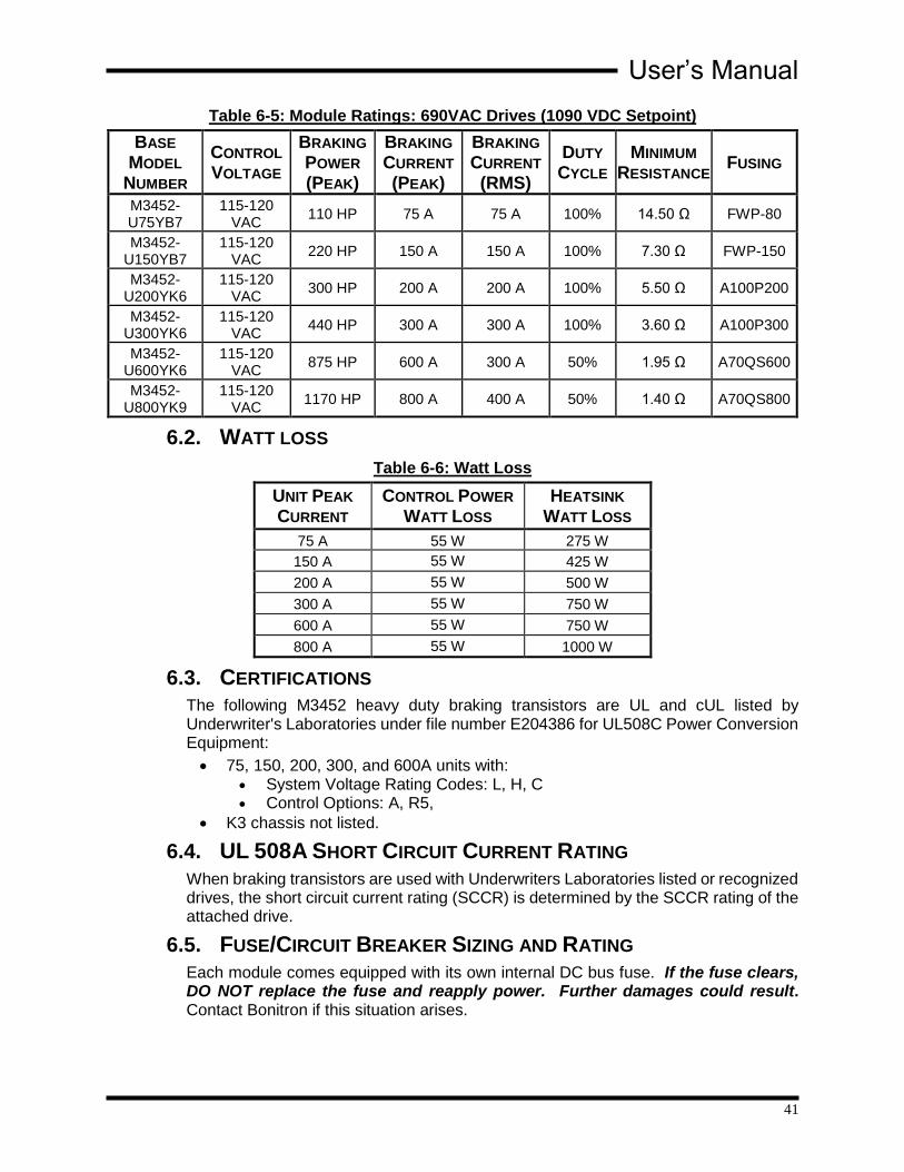
Table 6-5: Module Ratings: 690VAC Drives (1090 VDC Setpoint)
BASE
MODEL
NUMBER
CONTROL
VOLTAGE
BRAKING
POWER
(PEAK)
BRAKING
CURRENT
(PEAK)
BRAKING
CURRENT
(RMS)
DUTY CYCLE
MINIMUM
RESISTANCE FUSING
M3452-U75YB7
115-120 VAC
110 HP 75 A 75 A 100% 14.50 Ω FWP-80
M3452-U150YB7
115-120 VAC
220 HP 150 A 150 A 100% 7.30 Ω FWP-150
M3452-U200YK6
115-120 VAC
300 HP 200 A 200 A 100% 5.50 Ω A100P200
M3452-U300YK6
115-120 VAC
440 HP 300 A 300 A 100% 3.60 Ω A100P300
M3452-U600YK6
115-120 VAC
875 HP 600 A 300 A 50% 1.95 Ω A70QS600
M3452-U800YK9
115-120 VAC
1170 HP 800 A 400 A 50% 1.40 Ω A70QS800
6.2. WATT LOSS
Table 6-6: Watt Loss
UNIT PEAK
CURRENT CONTROL POWER
WATT LOSS HEATSINK
WATT LOSS
75 A 55 W 275 W
150 A 55 W 425 W
200 A 55 W 500 W
300 A 55 W 750 W
600 A 55 W 750 W
800 A 55 W 1000 W
6.3. CERTIFICATIONS The following M3452 heavy duty braking transistors are UL and cUL listed by Underwriter's Laboratories under file number E204386 for UL508C Power Conversion Equipment:
75, 150, 200, 300, and 600A units with: System Voltage Rating Codes: L, H, C Control Options: A, R5,
K3 chassis not listed.
6.4. UL 508A SHORT CIRCUIT CURRENT RATING
When braking transistors are used with Underwriters Laboratories listed or recognized drives, the short circuit current rating (SCCR) is determined by the SCCR rating of the attached drive.
6.5. FUSE/CIRCUIT BREAKER SIZING AND RATING
Each module comes equipped with its own internal DC bus fuse. If the fuse clears, DO NOT replace the fuse and reapply power. Further damages could result. Contact Bonitron if this situation arises.

M3452-A and -R5
42
If you wish to place fuses in your DC link, coordinate the fuse size with the proper wire size used in your link as per local codes and regulations. Fast acting semiconductor type fuses should be used.
6.6. DC BUS LINK LENGTH LIMITS The distance that the chopper is mounted from the main DC bus filter capacitors within the drive is limited by the amount of inductance in the connection. During switching, the inductance in the DC bus between the chopper and capacitors stores energy that must be absorbed by the snubbing circuit in the chopper.
In general, this distance should be kept to a maximum of 30 feet total (10m), or 15 feet (5m) for the DC+ link and 15 feet (5m) for the DC- link.
The values listed in Table 6-7 are the maximum inductance allowed in the DC bus link to and from the filter capacitors in the drive and the chopper connections.
Table 6-7: Maximum Inductance for DC Link Cable
UNIT PEAK
CURRENT MAXIMUM
INDUCTANCE
75 A 4.4 mH
150 A 1.1 mH
200 A 620 µH
300 A 275 µH
600 A 70 µH
800 A 39 µH
The distance between the DC bus filter capacitors and the braking chopper can be increased by using lowering the inductance of the buswork or cables. Typically this means using buswork or cable with a higher cross sectional area. The inductance of the buswork can be calculated from the length and inductance/foot published by the cable manufacturer. There are also standard tables to help this calculation.
If there is an extreme distance with inductance that cannot be removed from the DC bus, additional bulk capacitance can be added to decouple the DC bus inductance from the system, or the chopper can be repositioned to minimize the distance from the DC bus filter capacitance.
Figure 6-1: DC Link
AC
Drive
DC+
DC-
Braking
Chopper
Res
Res
DC+
DC-
Braking
Resistor
Res
Res
DC Bus
Link
Resistor
Link
6.7. RESISTOR LINK LENGTH LIMITS The distance that the resistor is mounted from the chopper is not a concern for the chopper as the components used will not be affected by this inductance.
Some ceramic or wirewound resistors can have significant inductance, grid or plate resistors do not. In very extreme cases, the inductance of the resistor and connecting cables may limit the rise time of the current to the resistor, but this will not have an impact on chopper operation.
Dwg: 130025 Rev: 20130122
User’s Manual
43
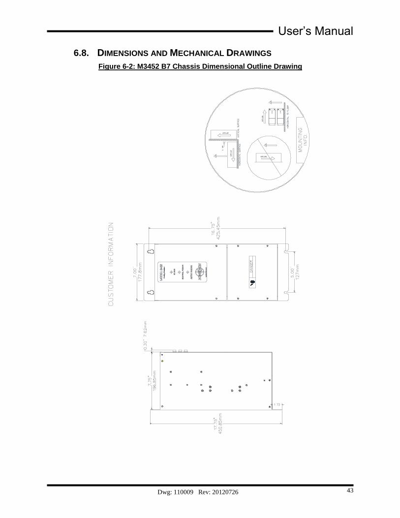
6.8. DIMENSIONS AND MECHANICAL DRAWINGS
Figure 6-2: M3452 B7 Chassis Dimensional Outline Drawing
Dwg: 110009 Rev: 20120726

M3452-A and -R5
44
Figure 6-3: M3452 K3 Chassis Dimensional Outline Drawing
Dwg: 050004 Rev: 20120726

User’s Manual
45
Figure 6-4: M3452 K6 Chassis Dimensional Outline Drawing
Dwg: 110010 Rev: 20120726

M3452-A and -R5
46
Figure 6-5: M3452 K9 Chassis Dimensional Outline Drawing
Dwg: 110038 Rev: 20120726

User’s Manual
47
6.9. BLOCK DIAGRAMS
Figure 6-6: Block Diagram
Dwg: 070165 Rev: 20120530

M3452-A and -R5
48
This page intentionally left blank

User’s Manual
49
7. APPENDICES
7.1. APPLICATION NOTES
7.1.1. SIZING YOUR BRAKING REQUIREMENTS Braking transistor modules are sized by peak current requirements and system voltage. Please use the following guidelines:
Verify the amount of peak power needed for braking. This must be determined from the mechanical system layout, and should be calculated in either peak watts or horsepower.
VFD’s are rated for braking power as well as peak braking capacity. This information is available in the drive manual. This will be the maximum amount of power that the output inverter stage of the VFD can absorb from the load before having an overcurrent condition. Refer to your VFD documents for information on drive sizing. Keep in mind that the current rating of the drive is for three phase current, not DC bus current. The braking current in the DC bus will be higher than the AC current absorbed from the load.
Because Bonitron braking transistor Modules are rated for peak current, determine the peak braking power required.
7.1.1.1. HORSEPOWER TO WATTS
Once the braking requirements for the mechanical load are determined, multiply the horsepower by the scaling factor of 746 to determine the wattage required. For instance, with a 400 hp system, the peak braking power may be 600 hp. In this case the peak power required would be:
746*.. Brakingbrake PHP wattsPHPbrake 447600746*..600
7.1.1.2. PEAK AMPERAGE
The peak amperage of the braking cycle can be determined by dividing the peak braking wattage by the system bus trip point of the braking transistor module used. If the above example were on a 480VAC system, the trip point is 750VDC, as determined from Table 2-3. In this case the peak current required would be:
VDCPI Brakingbrake 750/. ADCVDCwattsIbrake 596.8750/447600
In this case, a 600 amp module should be used.
7.1.1.3. OHMIC VALUE
The ohmic value of the resistive load can usually be determined from the ratings charts in Section 6.1. The ohmic value shown indicates the capacity of the braking transistor module, and may not be directly related to the horsepower of the drive. In order to calculate the required ohmic value for the braking load, use the following formula:
brake
DCbusbrake P
VR
2)(
The DC bus voltage for the equation is determined by the level that the drive begins braking. For 460/480VAC systems, this is typically 750VDC, for 230VAC systems, it is typically 375VDC. Refer to your drive manual for specifics.

M3452-A and -R5
50
For the above example, the ohmic value would be:
ohmswatts
VDCRbrake 26.1
447600)750( 2
This value must be verified with the ratings of the braking transistor module selected that it is not less than the “minimum ohmic value” for that model. If so, the braking requirements may be more than the braking transistor module can absorb, and a larger module may be required.
It is also possible to parallel two modules with two separate braking resistors to achieve the braking power required.
If the ohmic value calculated is greater than the value listed in the ratings table, it is possible to select a resistor value lower than the calculated value.
7.1.1.4. DUTY CYCLE
The duty cycle is based on the amount of time the drive is actually braking as opposed to accelerating, running at constant speed, or idle. For instance, if a pick and place operation requires 3 seconds to accelerate, traverses for 44 seconds and then decelerates for 3 seconds, the total cycle time is:
sec503443 decrunacccycle TTTT
The duty cycle for braking is:
%606.% cycle
decduty T
T
This rating assumes the load will be linearly decreasing from peak braking power to zero braking as the load comes to a stop.
Check this rating against the modules duty cycle rating, and if it is higher than rated, go to the next higher rated module. If a duty cycle is required over 50%, please call for assistance with your application.
7.1.1.5. CONTINUOUS RATING
The continuous rating is listed for long term heating calculations should the unit be installed in an area where heat dissipation is an issue. The rating is based on a triangular cycle that starts at peak value and reduces to zero within the rated duty cycle. Therefore, the average braking power during the deceleration cycle is ½ the power required if full power was required during the entire braking cycle. This value is:
2/%* dutypeakcontinuous PP
For the above example, the
WWPcontinuous 342812/%6*447600
User’s Manual
51
7.1.3. COMMON BUS APPLICATION NOTE Bonitron dynamic braking transistor modules are designed to be compatible with individual stand-alone inverter/drive systems, or systems that incorporate a common DC bus arrangement. The common DC bus can be composed of multiple inverter/drive sections tied together where all or some of the sections use their respective AC input, or there may be a large independent Master DC bus supply feeding the DC inputs of all inverter/ drive sections. In the case of the large Master DC bus supply, it is common to find multiple rectifier sections in parallel to provide very high power levels. Some high power systems also include redundant or back up sections as well.
Once power is applied, all Bonitron modules are designed to be sourced from DC buses that have all the bus capacitors present.
Common DC bus systems composed of separate Master DC bus or rectifier sections have important imbedded differences. It is common to have a main distributed DC bus, and this is typically where the dynamic braking transistor modules connect. In this way, the dynamic braking system is always present, even if some of the inverter/drive sections need to be removed from the bus for maintenance or other purposes. In emergency situations, it may even be necessary to “limp” along until repairs or swap outs can occur. Even though the modules are well suited for use in these systems, the following modes of operation could arise or exist and are not allowed:
1. Do not connect the dynamic braking transistor module on the rectifier side of a DC link choke. The connections must always be made to the inverter/drive side directly to the DC bus capacitors. During normal system operation, the choke can cause the braking system to begin ringing. This ringing causes high voltages that will damage the system.
2. Do not energize the system with no inverters/drives present on the distributed DC bus.
3. Do not energize, operate, or run the system with less than 60% of the total expected system capacitance present.
4. Operating the modules in conditions 2 and 3 may make the modules respond to inbound line transients caused by SCR type rectifiers, powering up the system, or any number of other sources. Without sufficient DC bus capacitance, the DC bus will not be filtered, and can cause ringing that will produce high voltages that will damage the system.
5. In some drives, the pre-charge contactor may open under fault conditions, leaving the bulk system capacitance only resistively coupled to the dynamic braking transistor modules. Do not enable the modules in this situation. Review inverter/drive DC bus pre-charge circuit operation with the drive manufacturer.
If there is the possibility of these situations:
Use a properly rated contactor in series with the modules’ control voltage AC Input. The modules are effectively disabled when they do not have their control power.
Keep the modules disabled during power up or any other time until all system capacitances are present.
Disable the modules in the event system pre-charge contactors open.
Always consult Bonitron with any questions or concerns surrounding this
M3452-A and -R5
52
topic.
7.1.4. BONITRON LINE REGENERATION MODULES The Bonitron M3645 line regens return regenerative energy back onto the AC line instead of dissipating the energy as heat in a resistor, and are ideal for applications with high duty cycles, frequent deceleration, or where heat from a resistor may be an issue. The regenerated energy is returned to the AC line with near-unity power factor and can be used to power other equipment, which quickly offsets the slightly higher initial investment of the line regen solution.

User’s Manual
53
NOTES

M3452-A and -R5
54


D_M3452_CMAN_vB7K369all_R2AR5_04l 04/20/2016
521 Fairground Court Nashville, TN 37211 USA
Tel: (615) 244-2825 Fax: (615) 244-2833 Web: www.bonitron.com Email: [email protected]