model hw-ecm installation, operation & maintenance …
TRANSCRIPT

HWL2-1019
IN UNITED STATES: 260 NORTH ELM ST. WESTFIELD, MA 01085 800-465-8558 / FAX (413) 564-5815IN CANADA: 7555 TRANMERE DRIVE, MISSISSAUGA, ONTARIO, L5S 1L4 (905) 670-5888 / FAX (905) 670-5782
MODEL HW-ECMINSTALLATION, OPERATION & MAINTENANCE
MANUALLow Temperature
High Wall Heating/Cooling Fan Coil Units up to 2 Ton Capacity
A. General Description ...........................................................2B. Technical Data .................................................................3-5 GeneralSpecification ...........................................................3 CoilData ..............................................................................4SoundPowerandPressureData ........................................4 DimensionalDrawings .........................................................5C. Service and Installation ................................................6-11 InstallationofHigh-WallUnit ................................................6 SelectingaLocation ............................................................6 MountingPlateDimensions .................................................7InstallingtheMountingPlate ................................................7 DrillingtheCondensateDrainageHole ...............................8 InstallingtheHydronicUnit ..................................................8 DrainagePipingWorks ........................................................8 UnitMaintenanceandPreparation ......................................9 OpeningandClosingofLift-UpGrilleCover ........................9 RemovingFrontCoverAssembly ........................................9 AirPurging ...........................................................................9 WiringConnections ..............................................................9
D. ControlSpecifications:CompleteControlPCB- S Type Control ............................................................10-14 DefinitionofInput/Output ...................................................10 WiringDiagramFullControlPCB–SControlType ..........11 ConfigurationSettings .......................................................12 ControlLogicsfor2-PipeSystem ......................................13 WithThermoelectricValveConfiguration ...........................13 SleepMode ........................................................................14 AutoFanSpeed .................................................................14 LEDLights .........................................................................14 LEDDisplayandErrorDescription ....................................14E. Users Interface .................................................................15 RemoteControlHandset ...................................................15F. Sensor Resistance R-T Conversion Table ................16-17G. Troubleshooting Guide ...................................................18H. Replacement Parts ..........................................................19

2
Every product is manufactured to meet thestringent requirements of the internationallyrecognized ISO 9001 standard for qualityassurance in design, development andproduction.
AllproductsconformtoULstandardforSafetyforHeatingandCoolingEquipmentUL19954thEdition,October14,2011;
AllproductsconformtoCSAstandardforSafetyforHeatingandCoolingEquipmentCSAC22.2No.236-11,4thEdition,October142011.
Allproductsconformtothe“WEEE”directivetoguarantee correct standards of environmentalsolutions.
ALWAYSMAKESURETHISMANUALREMAINSWITHTHEUNIT.READTHISMANUALBEFOREPERFORMINGANYOPERATIONON THE UNIT.
INVESTING IN QUALITY, RELIABILITY & PERFORMANCE.
World Leading Design and TechnologyEquipped with the latest air-conditioning testrooms and manufacturing technology, weproduceover50,000 fancoil unitseachyear,all conforming to the highest internationalstandardsofqualityandsafety.
The Highest Standards of ManufacturingInordertoguaranteetheveryhigheststandardsand performance, wemanage every stage inthemanufacturingofourproducts.Throughoutthe production process we maintain strictcontrol, starting with our extensive resourcesin research and development through to thedesign and manufacture of almost everyindividualcomponent, frommoldedplastics totheassemblyofunitsandcontrollers.
Quality Controlled from Start to FinishOurhighly-trainedstaffandstrictqualitycontrolmethods enable us to produce products withan exceptional reputation for reliability andefficiency, maintained over many years. Aswell as full CE certification and ISO 9001,severalproductsrangeshaveUL/ETLsafetyapproval in the USA and Canada, EuroventperformanceandsoundcertificationaswellasROHS compliance for Europe, giving you theconfidenceofknowingourcompanyistherightchoicewhenselectingfancoilunits.
A. General Description
ThisHighWallUnitisdesignedtomeetandexceeddemandingrequirementsforefficiency,quietoperationandappearance.Thesleek profile and elegantly styled cabinet complements any interior design theme, while the microprocessor assures accurateenvironmentalcontrol.
Cabinet-thestylishcabinetisconstructedofdurableflameresistantacrylonitrile-butadiene-styrene(ABS)plastic.Thesilverwhitecolorandroundedcornersprovideitsmodernlook.
WaterCoil-thewatercoilhasalargeheattransfersurfaceandutilizesthelatestfinprofiletechnology.Itcombinesanadvancedtechnologyapproachwiththesecurityofatraditionaldesignregardingtubethickness.Thewatercoilisalsoequippedwithanairventvalveandawaterpurgevalve.
IntegralHoses -an integralhose isasyntheticelastomer tube,withstainlesssteelouterbraidingandbrassconnectors,whichenablesquick,lowcostconnectionswithnobrazing.
BlowerandMotor-theunitincorporatesonlyspeciallydesignedandtestedECmotors,allowingtheblowerwheeltoprovideoptimumperformanceinairflow-efficiencyandquietoperation.
Filters-washable,easy-to-remove,finemeshairfiltersarestandardtoallHighWallmodels.Tabslocatedonthefrontoftheunitcanbeunsnapped,allowingthefiltertobeeasilysliddownwardandremoved.Notoolsarerequired,noranydismantlingoftheequipment.
ISO 9001 QUALITY
ETL SAFETY STANDARDS
WEEE MARK

3
B. Technical DataGeneralSpecification–HW-ECMSeries
Productrange:HW-ECMHydronicHighWall2PipewithECMotorHW-[Size]-ECM 6 15 18
UnitConfigurationConfiguration 2-Pipe
NumberOfFanBlowers SinglePowerSupply (V/Ph/Hz) 115/1/60
PerformanceData
Air AirFlowH
CFM294 379 464
M 218 294 435L 171 218 335
Cooling
CoolingCapacityH
BTU/Hr
6968 10199 12590M 5519 8336 11018L 4604 6289 8987
SensibleCoolingCapacityH 4817 7031 8686M 3754 5659 7507L 3107 4202 6080
Heating HeatingCapacityH
BTU/Hr10832 15856 19572
M 8579 12959 17129L 7158 9777 13970
Electrical FanmotorpowerH
W18 22 30
M 13 15 20L 10 10 13
FanMotorRunningCurrent@H115V A .31 .38 .52Sound SoundPressureLevelH/M/L dB(A) 39/31/26 45/34/31 49/44/37
HydronicWeight
CoolingWaterFlowRateH
GPM1.39 2.03 2.52
M 1.1 1.68 2.2L 0.92 1.26 1.81
CoolingPressureDropH
Ft.wg7.9 9.7 13.5
M 5.3 6.9 10.8L 3.9 4.3 7.6
HeatingWaterFlowRate GPM Sameas"CoolingWaterFlowRate"@H/M/L
HeatingPressureDropH
Ft.wg7 9 12
M 4.8 6.2 9.7L 3.5 3.8 6.9
WaterContent gal 0.02 0.03 0.05Water Type NPTThreadedMale
Connections Inin 1/2Out
CondensateDrainageConnection 0.63NetWeight lbs 26.5 28.7 30.9
a.CoolingMode(2-Pipe): Returnairtemperature:80°FDB/67°FWB. Inlet/Outletwatertemperature:45°F/55°F
b.HeatingMode(2-Pipe): Returnairtemperature:70°F Inletwatertemperature:140°F
AirGrilleDistribution-allunitsareequippedwithbothdeflectorbladesandindependentdirectionalvanes,enablingsupplyairtobeautomaticallydistributed,andairflowanddirectiontobecustomized.
Microprocessorcontrols(S3type)ThePCB (printedcircuitboard)Modbusmicroprocessorcontrols functionalityof the indoor-fanmotor,watervalves (ON/OFFormodulating)andelectricheater(optional),tomaintainroomconditionsatauser-definedsetpoint.Temperaturesettings,fanspeedsandothercontrolfunctionscanbechangedbyeitherinfraredhandsetorwiredwallpad.
• HighefficiencyECmotor.• Cool,Heat,Auto,DehumidifierandFanmodes.• Sleep,Auto-Fan,DailyTimer,Auto-Restartwithmemoryfunctions.• Userfriendlyremotecontrol.• Heatandcooltemperatureprotectionsandsafetycutout.• Manualcontrolpanelincabinet.• Auxiliaryswitchforcoolingandheatingsignal.

4
SoundPowerData
Model HW-06-ECM HW-15-ECM HW-18-ECMSpeed (CFM) H(930) M(700) L(600) H(1150) M(800) L(700) H(1300) M(1100) L(900)Sound Power dB(A) 49.0 39.8 35.7 56.0 43.9 39.5 60.0 54.5 47.5
Sound Power in
1/3 Octave-bands under ESP:0Pa
20.0 Hz 15.8 19.8 17.1 21.1 19.9 19.9 14.7 23.8 19.025.0 Hz 14.0 19.5 17.2 22.6 19.7 17.7 21.4 17.9 17.931.5 Hz 23.2 16.6 21.8 22.7 16.3 18.4 21.2 17.9 19.140.0 Hz 19.9 14.8 13.4 23.6 16.3 17.6 28.1 19.1 17.650.0 Hz 22.0 17.8 16.6 20.3 20.2 18.9 23.2 26.0 20.863.0 Hz 24.7 19.8 16.7 28.4 23.4 20.8 34.4 29.1 23.380.0 Hz 26.1 20.3 12.4 32.1 21.0 21.8 38.8 31.2 26.0100.0 Hz 28.6 22.8 17.7 36.0 24.2 22.1 39.4 37.2 27.6125.0 Hz 32.1 26.3 25.9 38.0 27.3 26.3 43.2 34.6 28.8160.0 Hz 34.4 26.1 17.8 39.8 30.0 23.4 44.5 37.0 31.8200.0 Hz 33.2 26.0 17.7 39.2 29.6 23.9 44.6 37.5 31.3250.0 Hz 31.7 25.0 20.0 39.6 28.1 26.5 43.5 36.9 30.8315.0 Hz 35.2 25.6 22.1 40.9 30.5 25.7 45.0 40.4 34.3400.0 Hz 39.9 32.0 26.2 46.2 36.2 31.7 50.5 45.1 38.0500.0 Hz 42.3 31.1 25.1 47.5 37.9 32.4 50.9 46.3 41.3630.0 Hz 42.2 29.7 24.6 48.8 35.4 30.7 52.3 49.5 39.7800.0 Hz 37.6 27.9 22.6 46.5 32.8 28.2 50.8 44.4 37.21000.0 Hz 39.5 28.6 23.1 48.5 33.6 28.8 52.6 45.7 39.11250.0 Hz 36.3 24.7 21.0 45.2 30.5 24.3 49.1 43.9 35.01600.0 Hz 32.8 22.6 21.6 42.7 26.7 22.8 47.1 39.4 31.32000.0 Hz 29.6 20.8 19.8 39.4 23.4 21.2 44.4 36.8 28.02500.0 Hz 26.9 20.9 20.0 36.7 22.2 20.4 41.6 34.1 25.93150.0 Hz 24.5 20.9 20.7 33.3 21.9 20.9 38.3 31.3 23.74000.0 Hz 23.1 20.8 20.8 31.5 21.3 20.7 36.6 29.5 22.95000.0 Hz 21.8 20.7 20.6 27.8 20.9 20.6 32.7 25.9 21.66300.0 Hz 20.5 20.2 20.0 24.5 20.3 20.2 29.1 23.1 20.48000.0 Hz 19.2 19.2 19.1 21.2 19.2 19.1 24.6 20.5 19.310000.0 Hz 17.2 17.5 17.3 17.9 17.3 17.2 19.5 17.7 17.312500.0 Hz 14.3 14.5 14.4 14.6 14.4 14.5 15.3 14.5 14.416000.0 Hz 11.6 11.2 11.2 11.9 11.3 11.3 11.9 11.4 11.6
Model Fin Height (inch)
Fin Length (inch) Fins per Inch No. of Rows No. of Copper No. of Circuits Tube Diameter
(inch)HW-06-ECM 9.1 26.8
19.52 14 3 0.3
HW-15-ECM 9.1 26.8 2 22 4 0.3HW-18-ECM 14.1 26.8 2 34 5 0.3
CoilData–2-PipeSystems
5
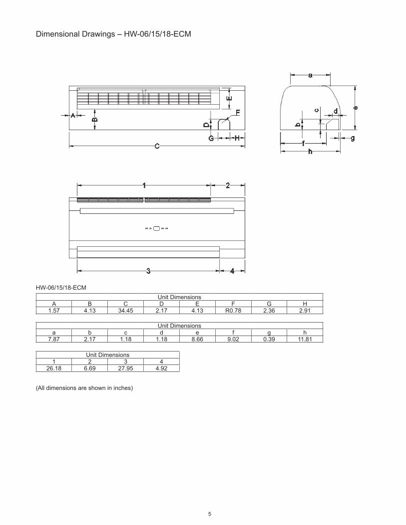
DimensionalDrawings–HW-06/15/18-ECM
(Alldimensionsareshownininches)
UnitDimensionsA B C D E F G H
1.57 4.13 34.45 2.17 4.13 R0.78 2.36 2.91
UnitDimensionsa b c d e f g h
7.87 2.17 1.18 1.18 8.66 9.02 0.39 11.81
UnitDimensions1 2 3 4
26.18 6.69 27.95 4.92
HW-06/15/18-ECM

6
C. Service and Installation
Operating Limits
PowerSupplies
WaterCircuit
InstallationofHighWallUnit
Selecting a Location
SelectthelocationfortheHighWallunitwiththefollowingconsiderations:1. Theairinletandoutletareashouldbeclearwithoutobstructions.Theairshouldflowfreely.2. TheHighWallunitshouldbemountedonsolidwall.3. Thelocationshouldalloweasyaccesstoconnectwaterpipeseasilyachievedrainage.4. Ensuretheclearancearoundthefancoilunitconformstothefollowingdrawing.5. Theunitshouldbeinstalledhigherthaneyelevel.6. Avoidinstallingtheunitwithdirectsunlight.
Notes:Requiredclearanceformaintenanceandservicingisasshownabove.Alldimensionsshownininches.
7. Thesignalreceiverontheunitmustbekeptawayfromanyhighfrequencyemissionsource.8. Keeptheunitawayfromfluorescentlamps,whichmayaffectthecontrolsystem.9. Avoidelectromagneticcontrolsysteminterference,ensurecontrolwiresareinstalledseparatelyfrom110VACpowersupplywires.10.Useshieldedsensorcableswhereelectromagneticwavespresent.11.Installanoisefilterifthepowersupplycreatesanydisruptivenoises.
Volt Phase Hz110-120 1 60
Minimumenteringwatertemperature 35.6°F(+2°C)Maximumenteringwatertemperature 176°F(+80°C)Maximumrecommendedenteringwatertemperature 167°F(+75°C)Watersiderecommendedmaximumpressure 250PSI(1724kPa)
Higher than eye level
7
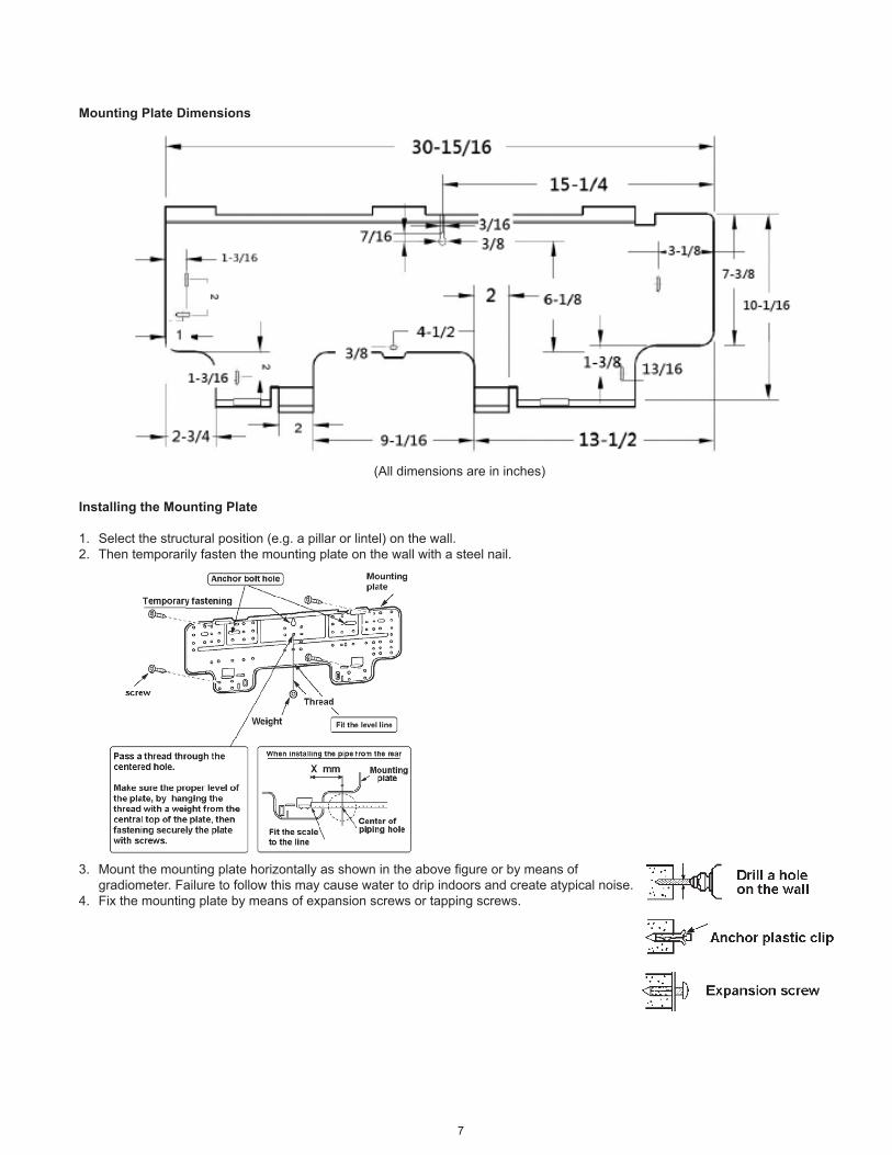
Mounting Plate Dimensions
Installing the Mounting Plate
1. Selectthestructuralposition(e.g.apillarorlintel)onthewall.2. Thentemporarilyfastenthemountingplateonthewallwithasteelnail.
3. Mountthemountingplatehorizontallyasshownintheabovefigureorbymeansof gradiometer.Failuretofollowthismaycausewatertodripindoorsandcreateatypicalnoise.4. Fixthemountingplatebymeansofexpansionscrewsortappingscrews.
(Alldimensionsareininches)

8
Drilling the Condensate Drain Hole
1. Ensurethattheholeforcondensatedrainiscorrectlypositioned.Theheightshouldbelowerthanthebottomedgeoftheindoorunit.
2. Drilla2.5"diameterholewithadescendingslope.3. Sealitoffwithputtyafterinstallation.
Installing the Hydronic Unit
1. Passthepipingthroughtheholeinthewallandhooktheindoorunitonthemountingplatebytheupperhooks.2. Movethebodyoftheunitfromsidetosidetoverifyifitissecurelyfixed.3. Whilepushingtheunittowardthewall,liftitslightlyfrombeneathtohookituponthemountingplatebythelowerhooks.4. Makesuretheunitfirmlyrestsonthehooksofthemountingplate.
Drain Piping Works
1. Installthedrainhosesothatitslopesdownwardslightlyforfreedrainage.Avoidinstallingitasshowninthebelowillustrationsmarkedwithan“X”.
2. Putwaterinthedrainpanandmakesurethatthewaterdrainsoutdoors.3. Iftheflexibledrainhoseprovidedwiththeindoorunitisnotlongenough,pleaseextenditbyjoiningittoafieldsuppliedextension.
Besuretoinsulatetheconnectingpartoftheextensionwithashieldpipeasshown.
4. Iftheattacheddrainhosepassesthroughanindoorarea,insulateitwithinsulationmaterial.

9
UnitMaintenanceandPreparation
Opening and Closing Of Lift-Up Grille Cover
Removing Front Cover Assembly
1. Setthehorizontallouvertothehorizontalposition.2. Removethescrewcapsbelowthelouver,andthenremovethemountingscrews.3. Openthelift-upgrillecoverbygraspingthepanelatbothsidesasshownabove.4. Removetheremainingscrewslocatedinthecenterofthefrontcover.5. Graspthelowerpartofthefrontcoverandpulltheentireassemblyoutanduptowardsyou.
Air Purging
1. After connecting thewater inlet and outlet pipes to themain supply lines turn on themain breaker and operate the unit inCOOLINGmode.
2. Openthewaterinletvalveandfloodthecoil.3. Checkallconnectionsforwaterleakage.Ifnoleakisfound,openthepurgingvalvewithanopenendwrenchwhilesupporting
theunitwithyourotherhand.Thenpurgetheairtrappedinsidethecoil.Whenperformingthisactivity,takecarenottotouchtheelectricalparts.
4. Closethepurgingvalvewhennobubblesappear.5. Openthewateroutletvalve.
Wiring Connections
Unitcomponentsarewiredtotheterminalblockoftheindoorunit.Wiringcanbeaccessedfromtheterminalblockinsidethecontrolbox.
Openthegrillecoverbyliftingfromthebottompositionindicatedbythearrows.
Closethegrillecoverbypressingdownatthepositionsindicatedbythearrows.

10
D.ControlSpecifications:CompleteControlPCB-STypeControl
Abbreviations Ts=Settingtemperature AUX1=Hotwaterfreecontact Tr=Roomairtemperature AUX2=Chilledwaterfreecontact Ti1=Chilledwatercoiltemperature MTV1=ChilledMotorizedvalve Ti2=Hotwatercoiltemperature MTV2=HotMotorizedvalve
DefinitionofInput/OutputI/O Code 2-Pipe
AnalogueInputReturnairsensor AI1 Returnairtemperature(Tr)
Coilsensor AI2 Chilled/hotwatercoilcircuit(Ti1)
Input LEDdisplay/IRreciever DIS1 DigitalcommunicationporttoLEDdisplay/IRreceiverboard.
Digitalinput Occupancycontact On/Off Windowcontacts:forremoteON/OFF(whenDIPBSW1=1).Economycontacts:forremoteactivationofeconomymode(whenDIPBSW1=0).
Powerinput
Phase L1
Powersupply:115V/1Ph/60HzNeutral N1
Earth
Voltageoutput
Fan CN4 Fandriver
Valve1 MTV1 2-pipecoilcircuitvalveoutput-chilled/hotwatervalve.Voltageoutput(L)
Valve2 MTV2 Reserved
Output
Steppingmotor CN1 / CN2 Louversteppingmotorrelay
Auxiliarycontact2 AUX2 Coolingmodesignalrelay(NO).Voltagefreecontact.Toensurethesensitivityoftheconnection,pleasemakesuremaxwiringlength<100ft.
Auxiliarycontact1 AUX1 Heatingmodesignalrelay(NO).Voltagefreecontact.Toensurethesensitivityoftheconnection,pleasemakesuremaxwiringlength<100ft.

11
WiringDiagramFullControlPCB-SControlType
Wiri
ng S
chem
atic
12
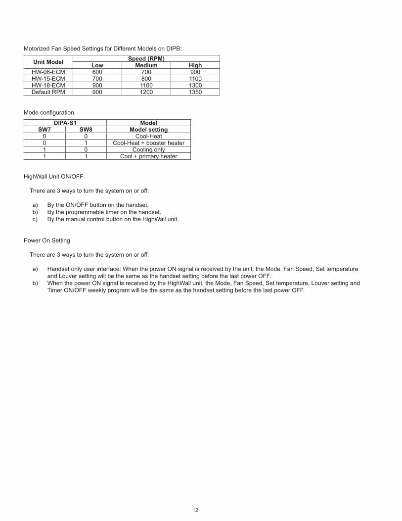
MotorizedFanSpeedSettingsforDifferentModelsonDIPB:
Modeconfiguration:
HighWallUnitON/OFF
Thereare3waystoturnthesystemonoroff:
a) BytheON/OFFbuttononthehandset. b) Bytheprogrammabletimeronthehandset. c) BythemanualcontrolbuttonontheHighWallunit.
PowerOnSetting
Thereare3waystoturnthesystemonoroff:
a) Handsetonlyuserinterface:WhenthepowerONsignalisreceivedbytheunit,theMode,FanSpeed,Settemperature andLouversettingwillbethesameasthehandsetsettingbeforethelastpowerOFF.
b) WhenthepowerONsignalisreceivedbytheHighWallunit,theMode,FanSpeed,Settemperature,Louversettingand TimerON/OFFweeklyprogramwillbethesameasthehandsetsettingbeforethelastpowerOFF.
Unit Model Speed (RPM)Low Medium High
HW-06-ECM 600 700 900HW-15-ECM 700 800 1100HW-18-ECM 900 1100 1300DefaultRPM 900 1200 1350
DIPA-S1 ModelSW7 SW8 Model setting
0 0 Cool-Heat0 1 Cool-Heat+boosterheater1 0 Coolingonly1 1 Cool+primaryheater

13
ControlLogicsFor2-PipeSystem(StandardUnit)
WithThermoelectricValveConfiguration
COOL MODEa) MTV2,AUX1andheaterarealwaysoff.b) IfTr≥Ts+1.8ºF(or+7.2ºFifeconomycontactisactivated),thencooloperationisactivatedandMTV1andAUX2areturnedon.
Indoorfanrunsatsetspeed.c) IfTr<Ts,thencooloperationisterminatedandMTV1andAUX2areturnedoff.Indoorfanrunsatsetspeed.d) TherangeofTsis60.8-86ºFe) Indoorfanspeedcanbeadjustedtolow,medium,highandauto.f) Whenturnedon,MTV1requires30secondsbeforeitisfullyopen.g) Whenturnedoff,MTV1requires120secondsbeforeitisfullyclosed.h) Whentheunitisturnedoff,theindoorfanwillshutdownafter5seconds.
LOW TEMPERATURE PROTECTION OF INDOOR COILa) IfTi1≤35.6ºFfor2minutes,thenMTV1andAUX2areturnedoff.Ifindoorfanissetforlowspeed,itwillrunatmediumspeed.If
itissetatmediumorhighspeed,itwillkeeprunningatthesamespeed.b) IfTi1≥41ºFfor2minutes,thenMTV1andAUX2areturnedon.Indoorfanrunsatsetspeed.
FAN MODEa) Indoorfanrunsatthesetspeedwhileheater,MTV1,MTV2,AUX1andAUX2areturnedoff.b) Indoorfanspeedcanbeadjustedtolow,mediumandhigh.
PRE-HEATa) IfTi1<96.8ºF(or82.4ºFdependingonDIPsetting),thenMTV1andAUX1areturnedon,indoorfanrunsat200RPM.b) IfTi1≥100.4ºF(or86ºFdependingonDIPsetting),thenMTV1andAUX1areturnedon,indoorfanrunsatsetspeed.c) Iftheindoorcoiltemperaturesensorisdamaged,thenthepre-heattimeissetfor2minutes.Indoorfanrunsatsetspeed.
POST-HEATa) IfTi1≥100.4ºF,thenMTV1andAUX1areturnedoff.Indoorfancontinuestorunatsetspeed.b) If96.8ºF≤Ti1≤100.4ºF,thenMTV1andAUX1areturnedoff.Indoorfanmaintainsitsoriginalstate.c) IfTi1<96.8ºF,thenMTV1andAUX1areturnedoff.Indoorfanrunsat200RPM.d) Iftheindoorcoiltemperaturecoilisdamaged,thenthepost-heattimeissetfor3minuteswiththeindoorfanrunningatsetspeed.
OVER-HEAT PROTECTION OF INDOOR COILa) IfTi1≥167ºF,thenMTV1andAUX1areturnedoff.Indoorfanremainsonandrunsathighspeed.b) IfTi1<158ºF,thenMTV1andAUX1areturnedon.Indoorfanremainsonandrunsatsetspeed.c) Iftheindoorcoiltemperaturesensorisdamaged,thentheprotectionmodewillbeoverriddenandtheunitwillworkaccordingto
thepre-heatandpost-heatprogram.
DEHUMIDIFICATION MODEa) MTV2,AUX1andheaterarealwaysoff.b) IfTr≥77ºF,thenMTV1andAUX2willbeturnedonfor3minutes,andthenofffor4minutes.c) If60.8ºF≤Tr<77ºF,thenMTV1andAUX2willbeturnedonfor3minutes,andthenofffor6minutes.d) IfTr<60.8ºF,MTV1andAUX2willbeturnedofffor4minutes.e) Attheendoftheabovedehumidificationcycle,thesystemwilldecidethenextdehumidificationcontroloption.Indoorfanwillrun
atlowspeedthroughoutthedehumidificationprocess.
AUTOMODEa) Everytimetheunitisturnedon,MTV1isonwhileAUX1,AUX2andfanareoff.MTV2andtheheaterarealwaysoff.After120
seconds,thesubsequentoperationmodeisdecidedaccordingtothefollowing:i. Ifthecoiltemperaturesensor(Ti1)≥96.8°F,thenMTV1,AUX1andfanturnonoroffaccordingtoHEATmode.ii. IfTi1<96.8°F,thenMTV1,AUX2andfanturnonoroffaccordingtoCOOLmode.
b) UnitremainsinAUTOCOOLorAUTOHEATmodethroughouttheoperatingcycleuntiltheuserchangesthemodemanuallyorrestartstheunit.
c) ShouldtheTi1sensorfailorbedamaged,automodewillnotfunction.
Note:AUTOCOOLorAUTOHEAToperationsarethesameasCOOLorHEATmoderespectively.

14
SleepMode
a) Thesleepmodecanonlybesetwhentheunitisincoolmodeorheatmode.b) Ifthesleepmodeisactivatedwhentheunitisincoolmode,thentheindoorfanwillrunatlowspeedandTswillincreaseby3.6ºF
over2hours.c) Ifthesleepmodeisactivatedwhentheunitisinheatmode,thentheindoorfanwillrunatsetspeedandTswilldecreaseby3.6ºF
over2hours.d) Changingthemodeofoperationwillcancelthesleepmode.
Thecoolmodesleepprofileis: Theheatmodesleepprofileis:
AutoFanSpeed
Inthismode, thefanspeed isnotchangeduntil thefanhasrunformorethan30seconds.After30secondsthefanspeed ismodulatedaccordingtothedifferencebetweentheroomtemperatureandthesettemperature.Thecontrolleradjuststhemotorsignalinputfrom0to5VDCbyPIDcalculationevery10seconds.Theairflowisadjustedfrom15%to100%.
LEDLights
LEDDisplayandErrorDescription
For all units Power / Operation LED light (both green)
Uniton PowerLEDOff,OperationLEDOnUnitinstandby PowerLEDOn,OperationLEDOff
For all units - Operation LED light (Green)Blink LED
Display Error Description Reason RemedyGreenLEDblinks1times,stopsfor3s E1 Electricheaterfailure OnlyforunitwithEH. EH
safetyswitchisopen.1.Changefanspeedtohigh.2.ReplacethedamagedEHsafetyswitch.
GreenLEDblinks2times,stopsfor3s E2 Indoorcoilsensor2failure Ti2sensorunpluggedor
damaged.1.CheckifTi2plugisconnectedornot.2.Checkifsensor’sresistanceiscorrectornot.
GreenLEDblinks3times,stopsfor3s E3 Returnairsensorfailure Roomsensorunplugged
ordamaged.1.CheckifTrplugisconnectedornot.2.Checkifsensor’sresistanceiscorrectornot.
GreenLEDblinks4times,stopsfor3s E4 Indoorcoilsensor1failure Ti1sensorunpluggedor
damaged.1.CheckifTi1plugisconnectedornot.2.Checkifsensor’sresistanceiscorrectornot.
GreenLEDblinks5times,stopsfor3s E5 Indoorcoillow
temperatureprotectionWatertemperatureislowerthan37.4ºF. Checkthewatertemperature.
GreenLEDblinks6times,stopsfor3s E6 Indoorcoiloverheat
protectionWatertemperatureishigherthan158ºF. Checkthewatertemperature.
GreenLEDblinks9times,stopsfor3s E9 ECmotorfailure NoECmotorfeedback 1.CheckDIPB-SW5andSW6setting.
2.ChecktheECmotor.GreenLEDblinks11times,stopsfor3s E11 Anti-frozenprotection Whenunitisstandby,
Ti1<35.6ºF TurnonunittokeepTi1higherthan41ºF.
15
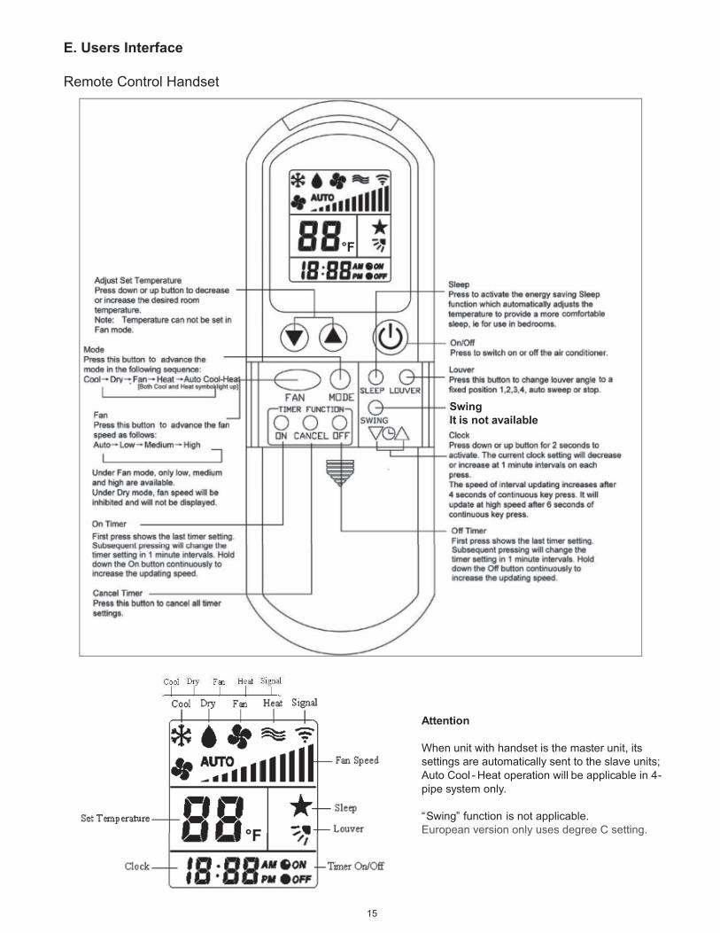
E. Users Interface
RemoteControlHandset
Attention
When unit with handset is the master unit, its settings are automatically sent to the slave units; Auto Cool - Heat operation will be applicable in 4-pipe system only.
“Swing” function is not applicable. European version only uses degree C setting.
Swing It is not available.
°F
°F

16
F. Sensor Resistance R-T Conversion Table
Resistance: R(77°F)=10KΩ±1%BetaConstant: B(25/85)=3977±1%
T Rmin Rnom Rmax T Rmin Rnom Rmax(°F) (KΩ) (KΩ) (KΩ) (°F) (KΩ) (KΩ) (KΩ)-22 174 182.7 191.8 39.2 26.11 26.9 27.71
-20.2 163.4 171.5 179.9 41 24.85 25.59 26.34-18.4 153.6 161.1 168.9 42.8 23.65 24.35 25.05-16.6 144.4 151.3 158.5 44.6 22.52 23.17 23.83-14.8 135.8 142.2 148.9 46.4 21.45 22.06 22.68-13 127.8 133.8 140 48.2 20.44 21.01 21.59
-11.2 120.3 125.8 131.6 50 19.48 20.02 20.55-9.4 113.3 118.4 123.8 51.8 18.58 19.7 19.58-7.6 106.7 111.5 116.5 53.6 17.71 18.18 18.65-5.8 100.6 105.1 109.7 55.4 16.9 17.33 17.77-4 94.9 99.03 103.3 57.2 16.12 16.53 16.94
-2.2 89.51 93.39 97.41 59 15.39 15.77 16.16-0.4 84.5 88.11 91.85 60.8 14.69 15.05 15.411.4 79.8 83.17 86.64 62.6 14.03 14.37 14.73.2 75.39 78.53 81.76 64.4 13.41 13.72 14.035 71.26 74.18 77.19 66.2 12.81 13.1 13.4
6.8 67.37 70.1 72.9 68 12.24 12.52 12.798.6 63.73 66.26 68.88 69.8 11.7 11.96 12.22
10.4 60.3 62.67 65.1 71.6 11.19 11.43 11.6712.2 57.08 59.28 61.55 73.4 10.71 10.93 11.1514 54.05 56.1 58.22 75.2 10.24 10.45 10.66
15.8 51.19 53.12 55.08 77 9.8 10 10.217.6 48.51 50.3 52.14 78.8 9.374 9.57 9.76519.4 45.98 47.66 49.37 80.6 8.969 9.16 9.35121.2 43.61 45.17 46.77 82.4 8.584 8.77 8.95723 41.36 42.82 44.31 84.2 8.218 8.4 8.582
24.8 39.25 40.61 42 86 7.869 8.047 8.22526.6 37.26 38.53 39.83 87.8 7.537 7.71 7.88528.4 35.38 36.56 37.78 89.6 7.221 7.39 7.5630.2 33.6 34.71 35.85 91.4 6.92 7.085 7.25132 31.93 32.97 3402 93.2 6.633 6.794 6.956
33.8 30.35 31.32 32.3 95 6.36 6.517 6.67535.6 28.85 29.76 30.68 96.8 6.099 6.252 6.40737.4 27.44 28.29 29.15 98.6 5.85 6 6.151

17
Resistance: R(77°F)=10KΩ±1%BetaConstant: B(25/85)=3977±1%
T Rmin Rnom Rmax T Rmin Rnom Rmax(°F) (KΩ) (KΩ) (KΩ) (°F) (KΩ) (KΩ) (KΩ)
100.4 5.614 5.759 5.907 167 1.417 1.474 1.532102.2 5.387 5.53 5.673 168.8 1.37 1.426 1.482104 5.172 5.31 5.451 170.6 1.326 1.379 1.434
105.8 4.966 5.101 5.238 172.4 1.282 1.335 1.389107.6 4.769 4.901 5.034 174.2 1.241 1.292 1.344109.4 4.582 4.71 4.84 176 1.201 1.25 1.302111.2 4.402 4.527 4.654 177.8 1.162 1.211 1.261113 4.231 4.353 4.477 179.6 1.125 1.172 1.221
114.8 4.067 4.186 4.307 181.4 1.089 1.135 1.183116.6 3.911 4.027 4.144 183.2 1.055 1.1 1.146118.4 3.761 3.874 3.989 185 1.021 1.065 1.111120.2 3.618 3.728 3.84 186.8 0.9891 1.032 1.077122 3.481 3.588 3.697 188.6 0.9582 1 1.044
123.8 3.35 3.454 3.561 190.4 0.9284 0.9697 1.012125.6 3.225 3.326 3.43 192.2 0.8998 0.9401 0.9818127.4 3.105 3.204 3.305 194 0.8721 0.9115 0.9522129.2 2.99 3.086 3.185 195.8 0.8455 0.8839 0.9237131 2.88 2.974 3.07 197.6 0.8198 0.8573 0.8961
132.8 2.774 2.866 2.959 199.4 0.795 0.8316 0.8696134.6 2.673 2.762 2.854 201.2 0.7711 0.8069 0.8439136.4 2.576 2.663 2.752 203 0.748 0.783 0.8192138.2 2.483 2.568 2.655 204.8 0.7258 0.7599 0.7953140 2.394 2.477 2.562 206.6 0.7043 0.7376 0.7722
141.8 2.309 2.39 2.472 208.4 0.6836 0.7161 0.7499143.6 2.227 2.306 2.386 210.2 0.6635 0.6953 0.7283145.4 2.149 2.225 2.304 212 0.6442 0.6752 0.7075147.2 2.073 2.148 2.224 213.8 0.6255 0.6558 0.6874149 2.001 2.074 2.148 215.6 0.6075 0.6371 0.6679
150.8 1.931 2.002 2.075 217.4 0.59 0.619 0.6491152.6 1.865 1.934 2.005 219.2 0.5732 0.6015 0.631154.4 1.801 1.868 1.937 221 0.5569 0.5846 0.6134156.2 1.739 1.805 1.872158 1.68 1.744 1.81
159.8 1.623 1.686 1.75161.6 1.569 1.63 1.692163.4 1.516 1.576 1.637165.2 1.466 1.524 1.583
18
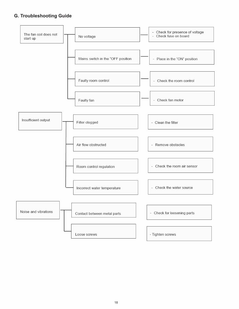
G. Troubleshooting Guide

19
H. Replacement Parts
Order Code Description HW-06 HW-15 HW-1845W37-WG1118-01 FrontLiftUpCover(accessfilters) x x x45W27-WG1119-01 AirInletFilter x x x45W37-WG1120-01 FrontCasing x x x45W37-WG1121-01 PowerInputCover x x x45W21-WG1122-01 ScrewCover x x x45W37-WG1123-01 RearCasing x x x45W40-WG1124-01 PipeClamp x x x45W31-WG1125-01 ECMotor x x x45W37-WG1126-01 MotorCover x x x45W34-WG1127-01 FanBlower x x x45W42-WG1128-01 FanBearing x x x45W06-WG1129-01 CondensatePan x x x45W06-WG1130-01 DrainPlug x x x45W37-WG1131-01 SwingLouverCollar x x x45W37-WG1132-01 VerticalLouver x x x45W45-WG1133-01 ConnectingRod x x x45W45-WG1134-01 SwingLouverCrank#1 x x x45W45-WG1135-01 SwingLouverCrank#2 x x x45W45-WG1136-01 CrankConnectionRod x x x45W37-WG1137-01 CrankCover x x x45W31-WG1138-01 LouverMotor x x x45W37-WG1139-01 UpperSwingLouver x x x45W37-WG1140-01 LoverSwingLouver x x x45W41-WG1141-01 CondensateDrainHose x x x45W43-WG1142-01 WallMountingPlate x x x45W09-WG1143-01 ReturnAirSensor x x x45W09-WG1144-01 ChilledWaterSensor x x x45W09-WG1145-01 HotWaterSensor x x x45W06-WG1146-01 LEDMount x x x45W37-WG1147-01 LEDCover x x x45W09-WG1148-01 IRReciever x x x45W43-WG1149-01 TerminalBlock x x x45W20-WG1150-01 WireRetentionClip x x x45W37-WG1151-01 LeftCoilBracket x x x45W50-WG1152-01 HydronicCoil x45W50-WG1153-01 HydronicCoil x45W28-WG1154-01 22"WaterHose x x x45W50-WG1156-01 HydronicCoil x45W11-WG1171-01 ControlBoardAssembly x x x

20
IN UNITED STATES: 260 NORTH ELM ST. WESTFIELD, MA 01085 800-465-8558 / FAX (413) 564-5815IN CANADA: 7555 TRANMERE DRIVE, MISSISSAUGA, ONTARIO, L5S 1L4 (905) 670-5888 / FAX (905) 670-5782