model gms81405dn * specifications - jmrmax.com · product specifications ... refer to the latest...
TRANSCRIPT
SS-GMS8 www.goodmanmfg.com 10/16Supersedes 9/15
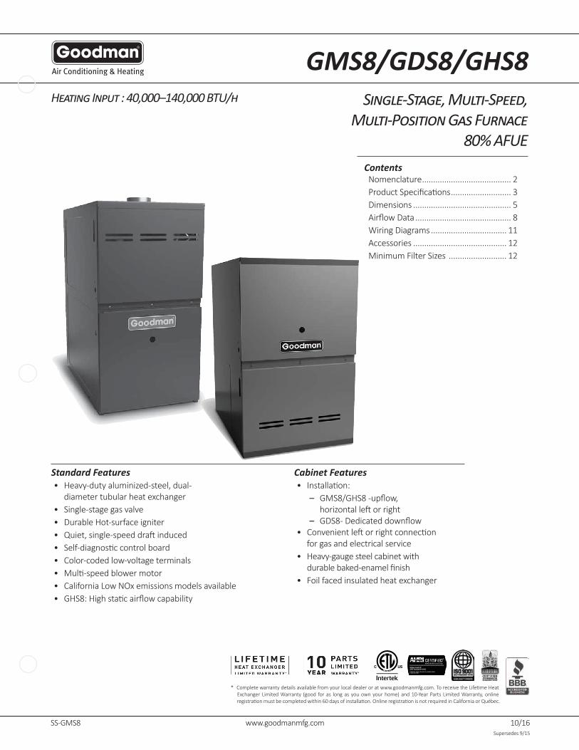
Heating Input : 40,000–140,000 BTU/h Single-Stage, Multi-Speed, Multi-Position Gas Furnace
80% AFUE
* Completewarrantydetailsavailablefromyourlocaldealeroratwww.goodmanmfg.com.ToreceivetheLifetimeHeatExchanger Limited Warranty (good for as long as you own your home) and 10-Year Parts Limited Warranty, online registrationmustbecompletedwithin60daysofinstallation.OnlineregistrationisnotrequiredinCaliforniaorQuébec.
Standard Features Cabinet Features• Heavy-dutyaluminized-steel,dual-
diameter tubular heat exchanger• Single-stage gas valve• DurableHot-surfaceigniter• Quiet,single-speeddraftinduced• Self-diagnosticcontrolboard• Color-coded low-voltage terminals• Multi-speedblowermotor• CaliforniaLowNOxemissionsmodelsavailable• GHS8:Highstaticairflowcapability
• Installation: – GMS8/GHS8-upflow, horizontalleftorright
– GDS8-Dedicateddownflow• Convenientleftorrightconnection
for gas and electrical service• Heavy-gaugesteelcabinetwith
durablebaked-enamelfinish• Foil faced insulated heat exchanger
ContentsNomenclature ........................................ 2ProductSpecifications ........................... 3Dimensions ............................................ 5AirflowData ........................................... 8Wiring Diagrams .................................. 11Accessories .......................................... 12MinimumFilterSizes .......................... 12
GMS8/GDS8/GHS8

2 www.goodmanmfg.com SS-GMS8
Nomenclature
G M S 80 040 3 B X **
1 2 4 5,6 7,8,9 10 11 12 13,14
Brand Engineering
G - Goodman® Brand Major/MinorRevisions
Configuration
M-Upflow/Horizontal NOx
C-Downflow/Horizontal N - Natural Gas
D-DedicatedDownflow X-LowNOx
Gas Valve
H-ConvertibleTwo-Stage,SinglePhase Cabinet Width
S - Single Stage, Single Speed A - 14" C - 21"
B - 17½" D - 24½"
AFUE
80-80%AFUE Maximum CFM
3 - 1200 CFM
MBTU/h 4-1600CFM
040-40,000BTU/h 100-100,000BTU/h 5 - 2000 CFM
060-60,000BTU/h 120-120,000BTU/h
080-80,000BTU/h 140-140,000BTU/h

SS-GMS8 www.goodmanmfg.com 3
GMS80403A*B
GMS80603A*B
GMS80604B*B
GMS80804B*B
GMS80805C*B
GMS81005C*B
GMS81205D*B
GMS81405DNC
Heating Capacity
Input 40,000 60,000 60,000 80,000 80,000 100,000 120,000 140,000
NaturalGasOutput 32,000 48,000 48,000 64,000 64,000 80,000 96,000 112,000
LPGasOutput 32,000 48,000 48,000 64,000 64,000 80,000 96,000 96,000
AFUE ¹ 80 80 80 80 80 80 80 80
Available AC @ 0.5” ESP 3 3 4 4 5 5 5 5
TemperatureRiseRange(°F) 25 - 55 20 - 50 20 - 50 35-65 35-65 35-65 40 - 70 40 - 70
Circulator Blower
Size(DxW) 10”x6” 10”x6” 10”x8” 10”x8” 10” x 10” 10” x 10” 11” x 10” 11” x 10”
Horsepower@1075RPM ⅓ ⅓ ½ ½ ½ ½ ¾ ¾
Speed 4 4 4 4 4 4 4 4
Vent Diameter ² 4" 4" 4" 4" 4" 4" 4" 4"
No. of Burners 2 3 3 4 4 5 6 6
Electrical Data
Min. Circuit Ampacity ³ 4.8 4.8 8.8 8.8 8.8 8.8 14.7 14.7
Max.OvercurrentDevice(amps)⁴ 15 15 15 15 15 15 15 15
Ship Weight (lbs) 84 88 98 106 114 118 130 130
AllmodelsavailableinCaliforniaLowNOx-compliantversions(exceptGMS81405D*C*)¹ DOEAFUEbaseduponIsolatedCombustionSystem(ICS)² Ventandcombustionairdiametersmayvarydependinguponventlength.RefertothelatesteditionsoftheNationalFuelGasCodeNFPA54/ANSI
Z223.1(intheUSA)andtheCanadaNationalStandardofCanada,CAN/CSAB149.1andCAN/CSAB142.2(inCanada).³ MinimumCircuitAmpacity=(1.25xCirculatorBlowerAmps)+IDBloweramps.WiresizeshouldbedeterminedinaccordancewithNationalElectrical
Codes.Extensivewirerunswillrequirelargerwiresizes.⁴ MaximumOvercurrentProtectionDevicereferstomaximumrecommendedfuseorcircuitbreakersize.
MayusefusesorHACR-typecircuitbreakersofthesamesizeasnoted.
Notes• Allfurnacesaremanufacturedforuseon115VAC,60Hz,single-phaseelectricalsupply.• GasServiceConnection½”FPT• Important:SizefusesandwiresproperlyandmakeelectricalconnectionsinaccordancewiththeNationalElectricalCodeand/orallexistinglocalcodes.
GMS8 Product Specifications

4 www.goodmanmfg.com SS-GMS8
GDS8/GHS8 Specifications
GDS80403A*B
GDS80603A*B
GDS80804B*B
GDS81005C*B
GHS80403A*B
GHS80604B*B
GHS80805C*B
Heating CapacityInput 40,000 60,000 80,000 100,000 40,000 60,000 80,000
NaturalGasOutput 32,000 48,000 64,000 80,000 32,000 48,000 64,000
LPGasOutput 32,000 48,000 64,000 80,000 32,000 48,000 64,000
AFUE ¹ 80 80 80 80 80 80 80
Available AC @ 0.5” ESP 3 3 4 5 3 4 5
TemperatureRiseRange(°F) 25 - 55 30-60 35-65 40 - 70 20 - 50 20 - 50 35-65
Circulator Blower
Size(DxW) 10”x6” 10”x6” 10”x8” 10” x 10” 11”x6” 11”x8” 11” x 10”
Horsepower@1075RPM 1/3 1/3 1/2 3/4 1/2 3/4 3/4
Speed 4 4 4 4 4 4 4
Vent Diameter ² 4” 4” 4” 4” 4” 4” 4”
No. of Burners 2 3 4 5 2 3 4
Electrical Data
Min. Circuit Ampacity ³ 4.8 4.8 8.8 10.5 10.5 13.7 13.7
Max.OvercurrentDevice(amps)⁴ 15 15 15 15 15 15 15
Ship Weight (lbs) 88 92 105 113 90 102 117
¹DOEAFUEbaseduponIsolatedCombustionSystem(ICS)²Ventandcombustionairdiametersmayvarydependinguponventlength.RefertothelatesteditionsoftheNationalFuelGasCodeNFPA54/ANSIZ223.1
(intheUSA)andtheCanadaNationalStandardofCanada,CAN/CSAB149.1andCAN/CSAB142.2(inCanada).³MinimumCircuitAmpacity=(1.25xCirculatorBlowerAmps)+IDBloweramps.WiresizeshouldbedeterminedinaccordancewithNationalElectrical
Codes.Extensivewirerunswillrequirelargerwiresizes.⁴MaximumOvercurrentProtectionDevicereferstomaximumrecommendedfuseorcircuitbreakersize.MayusefusesorHACR-typecircuitbreakersofthe
samesizeasnoted.
Notes• Allfurnacesaremanufacturedforuseon115VAC,60Hz,single-phaseelectricalsupply.• GasServiceConnection½”FPT• Important:SizefusesandwiresproperlyandmakeelectricalconnectionsinaccordancewiththeNationalElectricalCodeand/orallexistinglocalcodes.

SS-GMS8 www.goodmanmfg.com 5
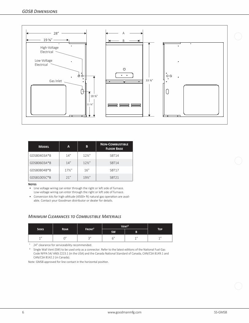
GMS8 Dimensions
28”
AB
1¾”
33⅜”
235⁄16”
17⁄16”
23¾”
13¼”
20”
27⅞”Alt. Gas Inlet
Alt. High Voltage
Alt. Low Voltage
Alternate Gas Inlet
High-Voltage Inlet
Low-Voltage Inlet
Alt.FlueOutlet—HorizontalLeft
➤
19½” ➤
➤
23” ➤
➤
15”
➤
➤
Minimum Clearances to Combustible Materials
Sides Rear Front¹Vent²
TopSW B
1” 0” 3” 6” 1” 1”
¹ 24” clearance for serviceability recommended.² SingleWallVent(SW)tobeusedonlyasaconnector.RefertothelatesteditionsoftheNationalFuelGas
CodeNFPA54/ANSIZ223.1(intheUSA)andtheCanadaNationalStandardofCanada,CAN/CSAB149.1andCAN/CSAB142.2(inCanada).
Note:GMS8approvedforlinecontactinthehorizontalposition.
Model A B Model A B
GMS80403A*B 14” 12½” GMS80805C*B 21” 19½”GMS80603A*B 14” 12½” GMS81005C*B 21” 19½”
GMS80604B*B 17½” 16” GMS81205D*B 24½” 23”
GMS80804B*B 17½” 16” GMS81405DNC* 24½” 23”
Notes• Linevoltagewiringcanenterthroughtherightorleftsideoffurnace.
Low-voltagewiringcanenterthroughtherightorleftsideoffurnace.• Conversionkitsforhigh-altitude(4500+ft)naturalgasoperationareavailable.
Contact your Goodman distributor or dealer for details.
6 www.goodmanmfg.com SS-GMS8
GDS8 Dimensions
Model A B Non-Combustible Floor Base
GDS80403A*B 14” 12½” SBT14
GDS80603A*B 14” 12½” SBT14
GDS80804B*B 17½” 16” SBT17
GDS81005C*B 21” 19½” SBT21
Notes• Linevoltagewiringcanenterthroughtherightorleftsideoffurnace.
Low-voltagewiringcanenterthroughtherightorleftsideoffurnace.• Conversionkitsforhigh-altitude(4500+ft)naturalgasoperationareavail-
able. Contact your Goodman distributor or dealer for details.
A
B
High-VoltageElectrical
Low-VoltageElectrical
Gas Inlet
19 ⅝”
28”
11 ⅜”
18 ⅜”
33 ⅜”
Minimum Clearances to Combustible Materials
Sides Rear Front¹Vent²
TopSW B
1” 0” 3” 6” 1” 1”
¹ 24” clearance for serviceability recommended.² SingleWallVent(SW)tobeusedonlyasaconnector.RefertothelatesteditionsoftheNationalFuelGas
CodeNFPA54/ANSIZ223.1(intheUSA)andtheCanadaNationalStandardofCanada,CAN/CSAB149.1andCAN/CSAB142.2(inCanada).
Note:GMS8approvedforlinecontactinthehorizontalposition.

SS-GMS8 www.goodmanmfg.com 7
GHS8 Dimensions
Model A B
GHS80403AXB* 14” 12½”
GHS80604BXB* 17½” 16”
GHS80805CXB* 21” 19½”
Notes• Linevoltagewiringcanenterthroughtherightorleftsideoffurnace.
Low-voltagewiringcanenterthroughtherightorleftsideoffurnace.• Conversionkitsforhigh-altitude(4500+ft)naturalgasoperationareavailable.
Contact your Goodman distributor or dealer for details.
28”
AB
1¾”
33⅜”
235⁄16”
17⁄16”
23¾”
13¼”
20”
27⅞”Alt. Gas Inlet
Alt. High Voltage
Alt. Low Voltage
Alternate Gas Inlet
High-Voltage Inlet
Low-Voltage Inlet
Alt.FlueOutlet—HorizontalLeft
➤
19½” ➤
➤
23” ➤
➤
15”
➤
➤
Minimum Clearances to Combustible Materials
Sides Rear Front¹Vent²
TopSW B
1” 0” 3” 6” 1” 1”
¹ 24” clearance for serviceability recommended.² SingleWallVent(SW)tobeusedonlyasaconnector.RefertothelatesteditionsoftheNationalFuelGas
CodeNFPA54/ANSIZ223.1(intheUSA)andtheCanadaNationalStandardofCanada,CAN/CSAB149.1andCAN/CSAB142.2(inCanada).
Note:GMS8approvedforlinecontactinthehorizontalposition.

8 www.goodmanmfg.com SS-GMS8
GMS8 Airflow Data
CFM & Temperature Rise vs. External Static Pressure
Model Motor Speed
Tons AC¹
External Static Pressure, (Inches Water Column)
0.1 0.2 0.3 0.4 0.5 0.6 0.7 0.8
CFM Rise CFM Rise CFM Rise CFM Rise CFM Rise CFM CFM CFM
GMS80403A*B
High 3 1,521 --- 1,466 --- 1,414 --- 1,373 --- 1,298 --- 1,243 1,164 1,075
Med 2.5 1,160 26 1,160 26 1,132 26 1,121 26 1,082 27 1,042 997 925
Med-Lo 2 961 31 955 31 948 31 932 32 913 33 882 821 803
Low 1.5 781 38 785 38 781 38 773 38 761 32 745 716 668
GMS80603A*B
High 3 1,422 31 1,352 33 1,307 34 1,197 37 1,157 38 1,092 1,075 983
Med 2.5 1,098 40 1,081 41 1,051 42 1,039 43 1,021 44 983 924 868
Med-Lo 2 919 48 913 49 892 50 847 ---- 829 ---- 818 792 728
Low 1.5 758 ---- 741 ---- 741 ---- 733 ---- 699 ---- 677 649 626
GMS80604B*B
High 4 2,134 21 2,100 21 2,042 22 1,975 23 1,883 24 1,786 1,700 1,601
Med 3.5 1,668 27 1,663 27 1,656 27 1,645 27 1,616 28 1,549 1,492 1,391
Med-Lo 3 1,419 31 1,426 31 1,426 31 1,432 31 1,419 31 1,378 1,328 1,261
Low 2.5 1,134 39 1,145 39 1,166 38 1,171 38 1,160 38 1,144 1,111 1,071
GMS80804B*B
High 4 2,051 ---- 1,983 ---- 1,895 --- 1,812 --- 1,725 --- 1,627 1,530 1,439
Med 3.5 1,736 --- 1,708 35 1,652 36 1,611 37 1,540 38 1,475 1,394 1,307
Med-Lo 3 1,493 35 1,668 36 1,459 41 1,429 41 1,389 43 1,339 1,274 1,204
Low 2.5 1,200 49 1,185 50 1,180 50 1,173 51 1,158 51 1,125 1,125 1,080
GMS80805C*B
High 5 2,290 ---- 2,229 ---- 2,155 ---- 2,047 ---- 1,960 ---- 1,837 1,712 1,584
Med 4 1,852 --- 1,820 --- 1,777 --- 1,719 --- 1,641 36 1,567 1,469 1,382
Med-Lo 3.5 1,615 37 1,592 37 1,556 38 1,516 39 1,470 40 1,405 1,346 1,235
Low 3 1,290 46 1,285 46 1,265 47 1,235 48 1,214 49 1,174 1,044 904
GMS81005C*B
High 5 2,323 --- 2,225 --- 2,120 35 2,040 36 1,974 38 1,801 1,688 1,577
Med 4 1,858 40 1,847 40 1,799 41 1,744 42 1,674 44 1,577 1,493 1,399
Med-Lo 3.5 1,596 46 1,587 47 1,571 47 1,552 48 1,493 50 1,397 1,326 1,217
Low 3 1,291 57 1,272 58 1,261 59 1,257 59 1,205 61 1,168 1,118 1,060
GMS81205D*B
High 5 2,469 --- 2,389 --- 2,300 --- 2,223 40 2,131 42 2,027 1,902 1,786
Med 4 1,575 56 1,558 57 1,545 58 1,513 59 1,500 59 1,419 1,354 1,271
Med-Lo 3.5 1,402 63 1,380 64 1,343 66 1,319 67 1,296 69 1,245 1,183 1,106
Low 3 1,200 ---- 1,186 ---- 1,161 ---- 1,127 ---- 1,082 ---- 1,042 995 926
GMS81405DNC*
High 5 2,469 42 2,389 43 2,300 45 2,223 47 2,131 49 2,027 1,902 1,786
Med 4 1,575 66 1,558 67 1,545 67 1,513 69 1,500 69 1,419 1,354 1,271
Med-Lo 3.5 1,402 ---- 1,380 ---- 1,343 ---- 1,319 ---- 1,296 ---- 1,245 1,183 1,106
Low 3 1,200 ---- 1,186 ---- 1,161 ---- 1,127 ---- 1,082 ---- 1,042 995 926
¹ at 0.5” ESPNotes:• CFMinchartiswithoutfilter(s).Filtersdonotshipwiththisfurnace,butmustbeprovidedbytheinstaller.Ifthefurnacerequirestworeturnfilters,this
chartassumesbothfiltersareinstalled.• Allfurnacesshipashigh-speedcoolingandmedium-speedheating.Installermustadjustblowercoolingandheatingspeedasneeded.• For most jobs, about 400 CFM per ton when cooling is desirable.• INSTALLATIONISTOBEADJUSTEDTOOBTAINTEMPERATURERISEWITHINTHERANGESPECIFIEDONTHERATINGPLATE.• Thischartisforinformationonly.Forsatisfactoryoperation,externalstaticpressuremustnotexceedvalueshownontheratingplate.• The dashed (----) areas indicate a temperature rise not recommended for this model.• Athigheraltitudes,aproperlyderatedunitwillhaveapproximatelythesametemperatureriseataparticularCFM,whileESPattheCFMwillbelower.

SS-GMS8 www.goodmanmfg.com 9
GDS8 Airflow Data
CFM & Temperature Rise vs. External Static Pressure
Model Motor Speed
Tons AC¹
External Static Pressure, (Inches Water Column)
0.1 0.2 0.3 0.4 0.5 0.6 0.7 0.8
CFM Rise CFM Rise CFM Rise CFM Rise CFM Rise CFM CFM CFM
GDS80403A*B
High 3.0 1,353 --- 1,290 --- 1,246 --- 1,199 25 1,149 26 1,116 1,116 1,099
Med 2.5 1,183 25 1,113 27 1,098 27 1,052 28 1,039 29 1,006 1,012 969
Med-Lo 2.0 980 30 946 31 920 32 900 33 896 33 885 855 804
Low 1.5 778 38 762 39 738 40 746 40 738 40 717 696 678
GDS80603A*B
High 3.0 1,290 34 1,236 36 1,194 37 1,166 38 1,176 38 1,166 1,108 1,029
Med 2.5 1,139 39 1,090 41 1,035 43 1,063 42 1,063 42 1020 962 895
Med-Lo 2.0 962 46 927 48 925 48 941 47 909 49 877 834 779
Low 1.5 787 56 776 57 763 58 744 60 723 --- 690 641 581
GDS80804B*B
High 4.0 2,128 --- 2,063 --- 2,001 --- 1,927 --- 1,824 --- 1,726 1,628 1,529
Med 3.5 1,840 --- 1,788 --- 1,745 --- 1,689 35 1,625 36 1,550 1,470 1,364
Med-Lo 3.0 1,602 37 1,558 38 1,543 38 1,493 40 1,455 41 1,402 1,328 1,239
Low 2.5 1,277 46 1,252 47 1,244 48 1,229 48 1,214 49 1,179 1141 1079
GDS81005C*B
High 5.0 2,405 --- 2,361 --- 2,250 --- 2,161 --- 2,037 36 1,937 1,808 1,689
Med 4.0 1,880 39 1,838 40 1,794 41 1,734 43 1,677 44 1,568 1,510 1,401
Med-Lo 3.5 1659 45 1,630 45 1,587 47 1,537 48 1,492 50 1,445 1,368 1,287
Low 3.0 1,472 50 1,454 51 1,404 53 1,366 54 1,326 56 1300 1228 1139
¹ at 0.5” ESP
GHS8 Airflow DataCFM & Temperature Rise vs. External Static Pressure
Model Motor Speed
Tons AC¹
External Static Pressure, (Inches Water Column)
0.1 0.2 0.3 0.4 0.5 0.6 0.7 0.8
CFM Rise CFM Rise CFM Rise CFM Rise CFM Rise CFM CFM CFM
GHS80403AXB*
High 3.0 1,739 --- 1,656 --- 1,601 --- 1,551 --- 1,513 20 1,460 1,413 1,353
Med 2.5 1,422 21 1,399 21 1,378 22 1,350 22 1,305 23 1,275 1,220 1,178
Med-Lo 2.0 1,207 25 1,213 24 1,197 25 1,169 25 1,158 26 1,131 1,103 1,068
Low 1.5 991 30 980 30 958 31 950 31 937 32 924 910 874
GHS80604BXB*
High 4.0 2,097 21 2,068 21 2,012 22 1,939 23 1,869 24 1,795 1,718 1,631
Med 3.5 1,596 28 1,566 28 1,534 29 1,492 30 1,445 31 1,401 1,354 1288
Med-Lo 3.0 1,380 32 1,356 33 1,328 33 1,303 34 1,274 35 1,239 1,192 1127
Low 3.0 1239 36 1191 37 1165 37 1133 39 1,104 40 1,082 1,040 996
GHS80805CXB*
High 5.0 2,382 --- 2,315 --- 2,234 --- 2,158 --- 2,078 --- 1,971 1,866 1,762
Med 4.0 1,622 37 1,603 37 1,583 37 1,556 38 1,516 39 1,482 1,422 1,359
Med-Lo 3.5 1,436 41 1,391 43 1,387 41 1,356 44 1,325 45 1,279 1,239 1,180
Low 3.0 1,240 48 1,214 49 1,191 50 1,157 51 1,120 53 1,083 1,052 1,025
¹ at 0.5” ESP
Notes• CFMinchartiswithoutfilter(s).Filtersdonotshipwiththisfurnace,butmustbeprovidedbytheinstaller.Ifthefurnacerequirestworeturnfilters,this
chartassumesbothfiltersareinstalled.• Allfurnacesshipashigh-speedcoolingandmedium-speedheating.Installermustadjustblowercoolingandheatingspeedasneeded.• For most jobs, about 400 CFM per ton when cooling is desirable.• INSTALLATIONISTOBEADJUSTEDTOOBTAINTEMPERATURERISEWITHINTHERANGESPECIFIEDONTHERATINGPLATE.• Thischartisforinformationonly.Forsatisfactoryoperation,externalstaticpressuremustnotexceedvalueshownontheratingplate.• The dashed (----) areas indicate a temperature rise not recommended for this model.• Athigheraltitudes,aproperlyderatedunitwillhaveapproximatelythesametemperatureriseataparticularCFM,whileESPattheCFMwillbelower.
10 www.goodmanmfg.com SS-GMS8
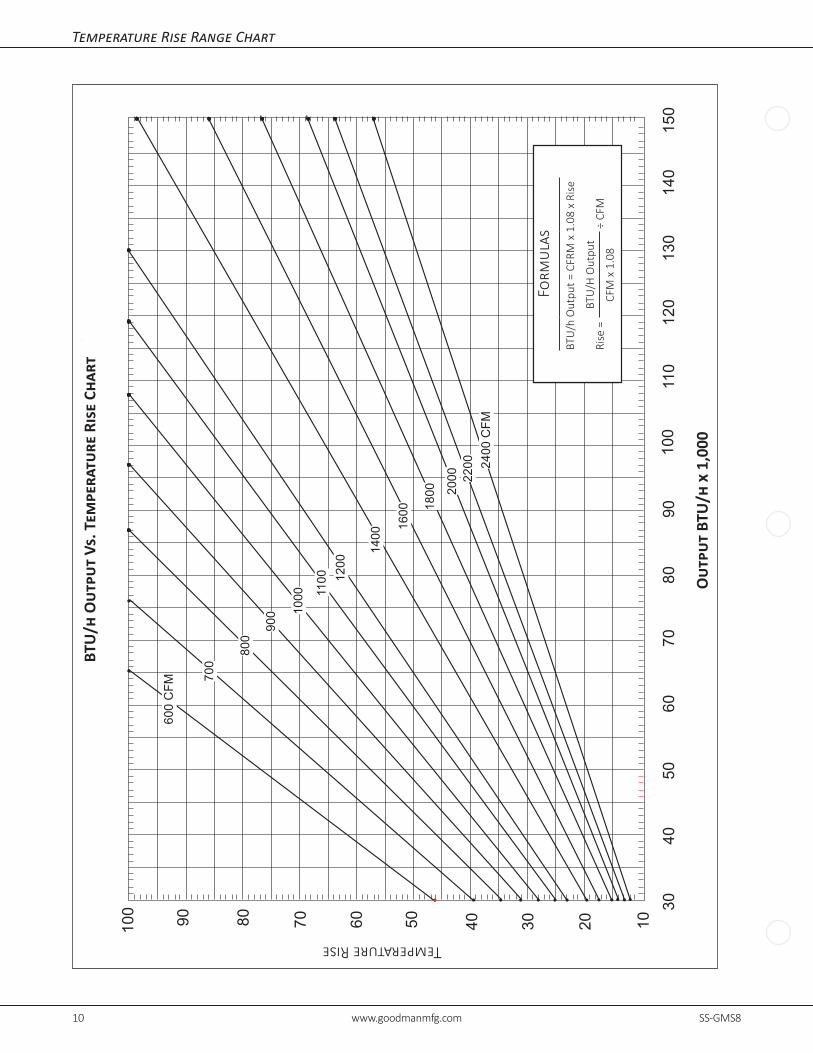
Temperature Rise Range Chart
3040
5060
7080
9011
012
010
013
014
015
0
100 90 80 70 60 50 40 30 20 10
OU
TPU
TBT
U/H
Rx
1000
BTU
OU
TPU
Tvs
TEM
PER
ATU
RE
RIS
EC
HAR
TTEMPERATURERISE
600
CFM
700
900 10
00 1100 12
00
1400
1600 18
00 2000 22
00 2400
CFM
FOR
MU
LAS
BTU
OU
TPU
T=
CFM
x1.
08x
RIS
E
RIS
E=
BTU
OU
TPU
T1.
08÷
CFM
800
TemperatureRise
Form
ulas
BTU/hOutpu
t=CFR
Mx1.08xRise
Rise=
BTU/H
Ou tpu
t ÷
CFM
CFMx1.08
BTU
/h O
utpu
t Vs
. Tem
pera
ture
Ris
e Ch
art
Out
put
BTU
/h x
1,0
00

SS-GMS8 www.goodmanmfg.com 11
Wiring Diagram
CAP
BK (HI)
AUXILIARYINTEGRATED
PROPERLY POLARIZED AND GROUNDED.SERVICING.WIRING TO UNIT MUST BEWARNING:DISCONNECT POWER BEFORE
FUSE
G C
6
3
9
12
WRR Y
5 4
1 2
8 7
11 10
OR
LEDDIAGNOSTIC
LINE-H XFMR-H HEAT-H COOL-H
CONTROL MODULE
BK
115 VAC HOT AND PARK TERMINALS
2
1
GR
PU
XFMR
BK
BK
BK
115V
24V
115 VAC NEUTRAL
BR
LIMITS
WH W
H (N)RD (LO
W)
OR (M
ED LOW
)BL (M
ED)
CICULATOR BLO
WER
24V THERMO
STAT CONNECTIO
NS
RO2 (11) LIMIT
GND (8)
HUMIDIFIER
XFMR (6) GND
G
C
W
Y TOMICRO
R
MV (12)
MVC (9)
AUXILIARYLIMIT CONTROLS
PS (10)
PSO (4)
HLI (7)
HLO (1)
CONTROL MODULEINTEGRATED
NO
SWITCHPRESSUREID BLOWER
VALVE
M1
GASC2
C
AUTO RESETPRIMARY
MANUAL RESET ROLLOUTLIMIT CONTROL(S)
115 VAC
FLAME SENSOR
FP (2)
XFMR-H
XFMR (3)
RO1 (5)
24 VAC
HOT SURFACEIGNITER
INTEGRATED CO
NTROL M
ODULEBR
BRCOOL-H
IGN
IND
IDBLWR
CIRCULATOR
HEAT-H
COOL
HEAT
BLWR
TRANSFORMER40 VA
CONTROL
XFMR-N
INTEGRATED CO
NTROL M
ODULECIR-N
0140F00119-C
5. UNIT MUST BE PERMANENTLY GROUNDED AND CONFORM TO N.E.C. AND LOCAL CODES.
ON SOME MODELS
HUMIDIFIER24 VAC
INDUCED DRAFT
C. USE COPPER CONDUCTORS ONLY.
BLOWER COMPARTMENT
BURNER COMPARTMENT
REPLACED, IT MUST BE REPLACED WITH WIRING MATERIAL HAVING A TEMPERATURE3. IF ANY OF THE ORIGINAL WIRE AS SUPPLIED WITH THE FURNACE MUST BE
CORRECT COOLING CFM. (SEE SPEC SHEET FOR AIR FLOW CHART) REQUIREMENTS SO AS TO PROVIDE THE CORRECT HEATING TEMPERATURE RISE AND THE4. BLOWER SPEEDS MUST BE ADJUSTED BY INSTALLER TO MATCH THE INSTALLATION
INTEGRATED CONTROL INTERNAL TO
2. MANUFACTURER'S SPECIFIED REPLACEMENT PARTS MUST BE USED WHEN SERVICING.1. SET HEAT ANTICIPATOR ON ROOM THERMOSTAT AT 0.7 AMPS.
BLOWER
GAS VALVE
PRIMARY LIMITBK
GR
WH
IGNITERSURFACEHOT M1
PU
WH
RD
WH
15 PIN PLUG
CNO
SWITCHPRESSURE
BR
C2
SENSORFLAME
BK
WH
ROLLOUT LIMITS
RAPID FLASHES = REVERSED 115 VAC POLARITY/VERIFY GND
1 FLASH = SYSTEM LOCKOUT (RETRIES/RECYCLES EXCEEDED)
7 FLASHES = LOW FLAME SIGNAL
5 FLASHES = FLAME SENSE WITHOUT GAS VALVE 4 FLASHES = OPEN HIGH LIMIT 3 FLASHES = PRESSURE SWITCH STUCK OPEN
2 FLASHES = PRESSURE SWITCH STUCK CLOSED
STEADY ON = NORMAL OPERATIONOFF = CONTROL FAILURE
5
0
1
2
3
4
PU
6 FLASHES = OPEN ROLLOUT
COLOR CODES:
PU PURPLEOR ORANGEYL YELLOW
6
7
C
BK BLACKGR GREEN
BR BROWNPK PINK
RD REDGY GRAYBL BLUEWH WHITE
PU
RATING OF AT LEAST 105�
NOTES:
TO 115VAC/ 1Ø /60 HZ POWER SUPPLY WITHOVERCURRENT PROTECTION DEVICE
JUNCTION BOX
MUST BE
WARNING:
SWITCH
WIRING TO UNITBEFORE SERVICING.DISCONNECT POWER
LINE-H
DOOR
AND GROUNDED.POLARIZEDPROPERLY
L GND
LINE-N
DISCONNECT
N
SWITCH (TEMP.)
FIELD SPLICE
SWITCH (PRESS.)
PROT. DEVICE OVERCURRENT
EQUIPMENT GND
TERMINAL
JUNCTION
HI VOLTAGE FIELD
HI VOLTAGE (115V)
LOW VOLTAGE FIELD
LOW VOLTAGE (24V)
PLUG CONNECTION
IGNITER
FIELD GND
IND-N
IGN-N
JUNCTIONBOX
OVERCURRENT PROTECTIONPOWER SUPPLY WITHTO 115 VAC/ 1/60HZ
GNDLINE-N
LINE H
DEVICE
DOOR SWITCH
WH
BK
SWITCH LOCATED IN BLOWERCOMPARTMENT ON SOME MODELS
RD
RD
RDBL
YL
YL
RDBL
BL
PU
YL
YL
BR
OR
OR
OR
YLYL
RDRD
WH
WH
WH
YL
OR
BKYL
BR
WH
(SINGLE CONTROL ON SOME MODELS)
(SINGLE CONTROL ON SOME MODELS)
24 VACHUMIDIFIER
Wiri
ng is
subj
ect t
o ch
ange
. Alw
ays
refe
r to
the
wiri
ng d
iagr
am o
n th
e un
it fo
r the
mos
t up-
to-d
ate
wiri
ng.⚠
War
ning
High
Vol
tage
: Di
scon
nect
all
pow
er b
efor
e se
rvic
ing
or in
stal
ling
this
unit.
Mul
tiple
pow
er
sour
ces m
ay b
e pr
esen
t. Fa
ilure
to d
o so
may
caus
e pr
oper
ty d
amag
e, p
erso
nal i
njur
y, or
dea
th.⚡

12 www.goodmanmfg.com SS-GMS8
Goodman Manufacturing Company, L.P., reserves the right to discontinue, or change at any time, specifications or designs without notice or without incurring obligations. ©2016 Goodman Manufacturing Company, L.P. • Houston, Texas • Printed in the USA.
Accessories
Downflow Sub-base for:
Model Description GDS80403A*B
GDS80603A*B
GDS80804B*B
GDS81005C*B
SBT14 14” Furnace √ √
SBT17 17½” Furnace √
SBT21 21” Furnace √
Model Description
LPT-03 ¹ LP Conversion Kit
HANG20 High-AltitudeNaturalGasKit(4500+ft)
AFE18-60A Fossil Fuel Kit
MVK-01 ² Masonry Vent Kit
MVK-02 ² MasonryVentKit(forGMS81205D*&GMS81405D*only)
FTK04 Twining Kit
¹ White-RodgersandHoneywellvalves² Upflowapplicationsonly
Minimum Filter Sizes
Model # GMS80403A*
GMS80603A*
GMS80604B*
GMS80804B*
GMS80805C*
GMS81005C*
GMS81205D*
GMS81405D*
FilterSize(in²)(1)16x25(Side)or (1)14x24(Bottom)
(1)16x25(SideorBottom)(1)16x25
(SideorBottom)¹(2)16x25(Side)or(1)20x25(Bottom)
(2)16x25(Side)or (1)24x24(Bottom)
Model # GDS8 0403A*
GDS8 0603A*
GDS8 0804B*
GDS8 1005C*
FilterSize(in²)(2) 10 x 20 or
(1)14x25(TopReturn)(2) 14xX 20 or
(1)16x25(TopReturn)(2) 14 x 20 or
(1)20x25(TopReturn)
Model # GHS8 0403A*
GHS8 0604B*
GHS8 0805C*
FilterSize(in²)(1)16x25(Side)or(1)14x24(Bottom)
(1)16x25(SideorBottom)
1-16X25(SideorBottom)¹
Note:Othersizefiltersofequalorgreatersurfaceareamaybeused;filtersmayalsobecentrallylocated.¹ Use2-16x25filtersonsidereturnsor20x25filteronbottomreturniffurnaceisconnectedtoacoolingunitover4tonsnominalcapacity.