model g-spa amplified speaker - fedsig.com 3 choosing cable-entry devices for equipment ... •...
TRANSCRIPT

25500188 BRev. B3 0917Printed in U.S.A.
Installation and Maintenance Instructions
Global Series Model G-SPA Amplified Speaker
For Use in Hazardous Locations
Ex d Surface Mount Ex de Surface Mount

Limited Warranty This product is subject to and covered by a limited warranty, a copy of which can be found at www.fedsig.com/SSG-Warranty. A copy of this limited warranty can also be obtained by written request to Federal Signal Corporation, 2645 Federal Signal Drive, University Park, IL 60484, email to [email protected] or call +1 708-534-3400.
This limited warranty is in lieu of all other warranties, express or implied, contractual or statutory, including, but not limited to the warranty of merchantability, warranty of fitness for a particular purpose and any warranty against failure of its essential purpose.
2645 Federal Signal DriveUniversity Park, Illinois 60484-3167
www.fedsig.com
Customer Support 800-344-4634 • +1 708 534-3400 Technical Support 800-524-3021 • +1 708 534-3400
Model G-SPA Global Series Amplified Speaker3
ContentsSafety Messages to Installers and Users ............................................. 5
Certification ............................................................................................. 6
Unpacking the Amplified Speaker ........................................................ 7
Creating Combination Fixtures in the Field ......................................... 8
Mounting the Amplified Speaker ......................................................... 10Mounting the Surface-Mount Ex d Amplified Speaker .................................. 10Mounting the Ex de Surface-Mount Amplified Speaker ................................ 11
Safety Messages for Wiring ................................................................. 13
Preparing to Wire the Ex d Flameproof Models ................................. 14Wiring the Ex d Models ...................................................................................... 16Adjusting the Sound Pressure and Audio Input (Ex d) .................................. 18
Preparing to Wire the Ex de Increased Safety Models ...................... 20Wiring the Ex de Models .................................................................................... 21Adjusting the Sound Pressure and Audio Input (Ex de)................................. 23
Safety Messages to Maintenance Personnel ..................................... 24
Maintaining the Amplified Speaker ..................................................... 25Cleaning the Enclosure ....................................................................................... 25Lubricating the Threaded Joints ......................................................................... 25
Ordering Replacement Parts and Accessories ................................. 25
Getting Technical Assistance or Repair Service ............................... 28
4 Model G-SPA Global Series Amplified Speaker
Contents
© 2017 Federal Signal Corporation. All rights reserved.
Tables
Table 1 Replacement part ...................................................................................25
Table 2 Accessories ............................................................................................26
Table 3 Choosing cable-entry devices for Equipment in Potentially Explosive Atmospheres ......................................................................................27
Figures
Figure 1 Beacon and amplified speaker combination fixture ................................9
Figure 2 Front view of Ex d amplified speaker....................................................10
Figure 3 Front view of Ex de surface mount ....................................................... 11
Figure 4 Side view of Ex de surface mount ........................................................12
Figure 5-A Ex d in/out PCB connections (2.8 V/0.8 Vrms) .................................15
Figure 5-B Ex d in/out PCB connections (25 Vrms) ...........................................15
Figure 6 Location of VR1 potentiometer (sound pressure) .................................18
Figure 7 Location of jumper JP3 (audio input) ...................................................19
Figure 8 Connections for DC or AC Ex de amplified speaker .............................21
5
Installation and Maintenance Instructions
Model G-SPA Global Series Amplified Speaker
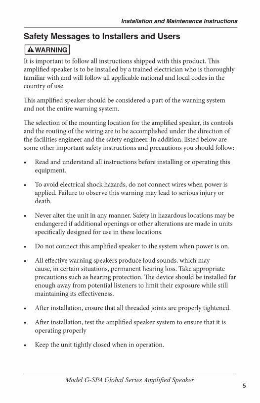
Safety Messages to Installers and Users
It is important to follow all instructions shipped with this product. This amplified speaker is to be installed by a trained electrician who is thoroughly familiar with and will follow all applicable national and local codes in the country of use.
This amplified speaker should be considered a part of the warning system and not the entire warning system.
The selection of the mounting location for the amplified speaker, its controls and the routing of the wiring are to be accomplished under the direction of the facilities engineer and the safety engineer. In addition, listed below are some other important safety instructions and precautions you should follow:
• Read and understand all instructions before installing or operating this equipment.
• To avoid electrical shock hazards, do not connect wires when power is applied. Failure to observe this warning may lead to serious injury or death.
• Never alter the unit in any manner. Safety in hazardous locations may be endangered if additional openings or other alterations are made in units specifically designed for use in these locations.
• Do not connect this amplified speaker to the system when power is on.
• All effective warning speakers produce loud sounds, which may cause, in certain situations, permanent hearing loss. Take appropriate precautions such as hearing protection. The device should be installed far enough away from potential listeners to limit their exposure while still maintaining its effectiveness.
• After installation, ensure that all threaded joints are properly tightened.
• After installation, test the amplified speaker system to ensure that it is operating properly
• Keep the unit tightly closed when in operation.

6
Installation and Maintenance Instructions
Model G-SPA Global Series Amplified Speaker
• After testing is complete, provide a copy of this instruction sheet to all personnel.
• Brass inserts have the potential to store charge when they are not plugged. Consideration should be taken to prevent these from becoming a sparking hazard.
• Establish a procedure to routinely check the amplified speaker system for proper activation and operation.
• This equipment is suitable for use in Class I, Division 2, Groups A, B, C, D; Class II, Division 2, Groups F and G; Class III or non-hazardous locations only.
• WARNING: EXPLOSION HAZARD — Do not disconnect the equipment unless power has been switched off or unless the area is known to be non-hazardous.
• WARNING: EXPLOSION HAZARD — Do not remove or replace the fuse when energized.
Failure to follow all safety precautions and instructions may result in property damage, serious injury, or death.
CertificationCertificate Nos.: ATEX Cert No.: Baseefa15ATEX0155X IECEx Cert No.: IECEx BAS 15.0104X ATEX coding: II 2 G DProtection: Ex db IIB T5 Gb or Ex db e IIB T5 Gb Ex tb IIIC T100°C Db IP66 (Tamb= -55°C to + 49°C) Ex db IIC T4 Gb or Ex db e IIC T4 Gb Ex tb IIIC T135°C Db IP66 (Tamb= -55°C to + 70°C) Standards: EN60079-0: 2012 +A11:2013, EN60079-1: 2014, EN60079-7: 2007, EN60079-31: 2014, IEC60079-0: 6th Ed., IEC 60079-1: 7th Ed., IEC 60079-7: 4th Ed., IEC 60079-31:2nd Ed

7
Installation and Maintenance Instructions
Model G-SPA Global Series Amplified Speaker
Specific Conditions of Use:
1. The Modular Audible Device enclosure incorporates a sinter and thevolume is greater than 100 cm3, therefore use of the Modular AudibleDevice in carbon disulphide gas atmospheres is not permitted.
2. The Modular Audible Device has external non-metallic surfaces whichmay provide electrostatic charging hazard. See the manufacturer'sinstructions for further information.
3. The Modular Audible Device has metallic components in the non-metallic walls of the enclosure which can store electrical charge andtherefore may provide a potential electrostatic discharge. The metallicbrass inserts have a capacitance of 24 pF. See the manufacturer'sinstructions for further information.
cULus Zone Certifications:Models that contain the Ex e increased safety (E-box) are not cULus Zone certified and not certified for use in Class, Zone locations. Only the following models are certified: G-SPA-MV-D and G-SPA-MVT. Please disregard any reference to the E-box when using these instructions for Class, Zone locations.
These models use protections:
Class I, Zone 1, A Ex db IIC T4
Zone 21, AEx tb IIIC T4/135°C IP66 (Tamb= -55°C to +70°C)
Ex db IIC T4
Ex tb IIIC T4/135°C IP66 (Tamb= -55°C to +70°C)
Unpacking the Amplified SpeakerAfter unpacking the amplified speaker, examine it for damage that may have occurred in transit. If it has been damaged, do not attempt to install or operate it. File a claim immediately with the carrier, stating the extent of the damage. Carefully check all envelopes, shipping labels, and tags before removing or discarding them. Disposal of all shipping materials must be carried out in accordance with national and local codes and standards. If any parts are missing, please call Federal Signal Customer Support at +1 708-534-4756 or +1 877-289-3246.

8
Installation and Maintenance Instructions
Model G-SPA Global Series Amplified Speaker
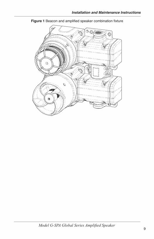
Creating Combination Fixtures in the FieldThe Federal Signal Global Series Ex de products can be connected together in the field using interchangeable E-box end caps and a proprietary coupling system.
The proprietary coupling system allows for simple and cost effective, wiring from product to product often eliminating the need for expensive Ex wiring practices and Ex rated glands. The E-box is available only when factory installed on an Ex d unit or when used as a E-box spacer adjoining an existing E-box. Please refer to the accessories listed on page 26 for available options. When creating certain fixture combinations, it is necessary to replace E-box end caps before mounting the product. If you are creating combination fixtures, refer to instruction manual 25500259 for specific instructions and details.
A note about combination fixtures: If the product is Ex db marked only, it is for use in gas atmospheres. If the product is Ex db e marked, it uses the increased-safety terminal enclosures and is only for gas atmospheres. If the product is Ex tb marked, it is for installation in dust atmospheres.
9
Installation and Maintenance Instructions
Model G-SPA Global Series Amplified Speaker
Figure 1 Beacon and amplified speaker combination fixture

10
Installation and Maintenance Instructions
Model G-SPA Global Series Amplified Speaker
Mounting the Amplified Speaker
ATTACH THE AMPLIFIED SPEAKER SECURELY: To prevent injury, this apparatus must be securely attached to the mounting surface in accordance with the installation instructions. Use installer-supplied fasteners suitable for the mounting surface.
The mounting method and the installer-supplied mounting hardware depend on which of the two G-SPA models you are installing:
Mounting the Surface-Mount Ex d Amplified SpeakerMount the amplified speaker to a flat surface using the four 8.5 mm mounting holes. Use installer-supplied fasteners suitable for the surface to which the device will be mounted.
Figure 2 Front view of Ex d amplified speaker
105.9 mm(4.17 in)
Ø133.8 mm (5.27 in)
4X COUNTER-BORED HOLES TO FIT M8 SOCKET-HEAD CAP SCREWS
105.9 mm(4.17 in)

11
Installation and Maintenance Instructions
Model G-SPA Global Series Amplified Speaker
Mounting the Ex de Surface-Mount Amplified SpeakerMount the amplified speaker to a flat surface using the six 8.5 mm mounting holes. Use installer-supplied fasteners suitable for the surface to which the device will be mounted.
Figure 3 Front view of Ex de surface mount
2X Ø8.5 mm
103.2 mm (4.06 in)
122.6 mm (4.83 in)
3X M20 GLAND
ENTRIES
4X COUNTER-BORED HOLES TO FIT M8 SOCKET-HEAD CAP SCREWS
105.9 mm(4.17 in)
23.2 mm (0.91 in)

12
Installation and Maintenance Instructions
Model G-SPA Global Series Amplified Speaker
Figure 4 Side view of Ex de surface mount
272.0 mm (10.71 in)
190.6 mm (7.50 in)
SEE ACCESSORIES FOR REPLACEABLE E-BOX END CAPS
3X M20 GLAND ENTRIES

13
Installation and Maintenance Instructions
Model G-SPA Global Series Amplified Speaker
Safety Messages for WiringWhen installing and operating flame-proof electrical equipment, the relevant national regulations for installation and operation (e.g., EN60079-14, IEC Wiring Regulations and NEC/CEC) must be observed.
• To avoid electrical shock hazards, do not connect wires when power is applied. Failure to observe this warning may lead to serious injury or death.
• To maintain the flame-proof integrity of the enclosure, DO NOT damage the cover or threads while disassembling or reassembling the unit.
• Painting and surface finishes, other than those applied by Federal Signal Corporation, are not permitted.
• Cable termination should be in accordance with specifications applying to the application. Federal Signal recommends that all cables and cores should be fully identified.
• Ensure that only the correct equipment-certified glands are used and that the assembly is shrouded and correctly earthed. Gland entries are M20-1.5 6H with an option for the M25 entry on the end of the increased safety box models. See Table 3 on page 26 for choosing correct cable entry devices for Equipment in Potentially Explosive Atmospheres.
• Because of space limitations, ensure the cable cores within the unit are not too slack.
• In all countries, the wiring must comply with all national and local codes and standards.
• Ensure that all nuts, bolts, and fixings are secure.

14
Installation and Maintenance Instructions
Model G-SPA Global Series Amplified Speaker
Preparing to Wire the Ex d Flameproof Models
SHOCK HAZARD: To avoid electrical shock hazards, do not connect wires when power is applied. Failure to observe this warning may lead to serious injury or death.
CIRCUIT BOARD DAMAGE: The DC amplified speakers are polarity sensitive, and MAY BE DAMAGED by incorrect electrical hookup. When connecting the DC amplified speaker to the voltage supply lines, POLARITY MUST BE OBSERVED. In addition, damage will result if the voltage rating of the particular model is exceeded by more than 10 percent.
This section has wiring instructions for the flameproof models G-SPA 24 Vdc, 120 Vac, 220-240 Vac.
The models come in either 25 Vrms or 2.8/0.8 Vrms (selectable) audio input versions.
Ex d units are supplied with a ten-position PCB mounted-screw terminal block. The maximum wire gauge is 4.0 mm2 (12 AWG). The wire must be rated 85 °C or higher. Use only stranded cable to terminate the amplified speaker. The cross-sectional area of the primary earth (ground) must equal the cross-sectional area of the phase conductor.
Cable termination for these models should be in accordance with specifications applying to the application. It is recommended that all cables and cores should be fully identified. Use the appropriate cable gland for the application. Gland entry threads are M20-1.5 x 6H.
Tools needed:• 1.5 mm A/F hexagon key• No. 1 Phillips screwdriver• Wire stripper

15
Installation and Maintenance Instructions
Model G-SPA Global Series Amplified Speaker
Figure 5-A Ex d in/out PCB connections (2.8 V/0.8 Vrms)
AUD− AUD+ EARTH L2 L1
VOLTAGE SELECTOR
Figure 5-B Ex d in/out PCB connections (25 Vrms)
EARTH
AC
DC 230
UU A
VOLTAGE SELECTOR
25 Vrms AUDIO PASSTHOUGH
25 Vrms AUDIO INPUT

16
Installation and Maintenance Instructions
Model G-SPA Global Series Amplified Speaker
Wiring the Ex d ModelsTo wire the Ex d flameproof amplified speaker:
1. Unscrew the M3 hex set screw on the side of the housing one full turn.
2. Remove the cover from the housing by turning the cover counter-clockwise. Three 120-degree spaced reliefs are provided for a 3/8 inch spanner wrench if needed. If the cover will not unscrew, back out the set screw a few additional turns.
3. Loosen the captive Phillips screw retaining the driver/printed circuit board (PCB).
4. Slide out the PCB until the terminals clear the housing. Strip the wire insulation 6.5 mm (0.25 in). Maximum screw tightening torque is 0.5 N•m (4.5 in-lb).
5. Follow the instructions below for your line voltage and continue to Step 6 on page 19. Refer to Figure 5-A or 5-B for the voltage selector switch.
120 Vac operation
a. Set the voltage selector switches to 120 and AC.
b. Connect the line (hot) power source wire to the terminal block position marked L1 on the PCB.
c. Connect the neutral (common) power source wire to the terminal block position marked L2 on the PCB.
d. Connect ground wire to the terminal block position marked EARTH.
e. Connect the positive (+) audio source wire to the terminal block position marked AUD+.
f. Connect the negative (–) audio source to the terminal block position marked AUD-.
17
Installation and Maintenance Instructions
Model G-SPA Global Series Amplified Speaker
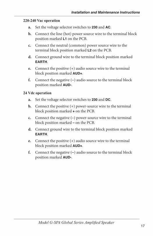
220-240 Vac operation
a. Set the voltage selector switches to 230 and AC.
b. Connect the line (hot) power source wire to the terminal block position marked L1 on the PCB.
c. Connect the neutral (common) power source wire to the terminal block position marked L2 on the PCB.
d. Connect ground wire to the terminal block position marked EARTH.
e. Connect the positive (+) audio source wire to the terminal block position marked AUD+.
f. Connect the negative (–) audio source to the terminal block position marked AUD-.
24 Vdc operation
a. Set the voltage selector switches to 230 and DC.
b. Connect the positive (+) power-source wire to the terminal block position marked + on the PCB.
c. Connect the negative (–) power-source wire to the terminal block position marked – on the PCB.
d. Connect ground wire to the terminal block position marked EARTH.
e. Connect the positive (+) audio source wire to the terminal block position marked AUD+.
f. Connect the negative (–) audio source to the terminal block position marked AUD-.

18
Installation and Maintenance Instructions
Model G-SPA Global Series Amplified Speaker
Adjusting the Sound Pressure and Audio Input (Ex d)Sound Pressure: See Figure 6. The 3/4-turn VR1 potentiometer on the PCB is factory-set to the maximum sound pressure level (MAX). To reduce the level, turn VR1 counter-clockwise to the desired setting.
Figure 6 Location of VR1 potentiometer (sound pressure)
VR1 POTENTIOMETER: FULL CLOCKWISE =
MAX. VOLUME

19
Installation and Maintenance Instructions
Model G-SPA Global Series Amplified Speaker
Audio Input: See Figure 7. Two audio input levels are available to match the audio level provided by the peripheral system. To change the level from 2.8 Vrms, move jumper JP3 to 0.8 Vrms. NOTE: This step is not necessary for the 25 Vrms versions. The jumper is factory-set.
Figure 7 Location of jumper JP3 (audio input)
JP3 JUMPER FOR AUDIO INPUT LEVEL
6. Insert the PCB into the enclosure and fully tighten the PCB captive screw.
7. Place the cover on the housing and tighten it by turning it clockwise.
8. To ensure O-ring compression, the cover must be fully seated against the housing when the threads are tightened. Turn the M3 set screw on the side of the housing until the screw contacts the housing.
9. Ensure that the unused wire entry is sealed with the provided brass M20-1.5 x 6 g stopping plug (equipment-certified).

20
Installation and Maintenance Instructions
Model G-SPA Global Series Amplified Speaker
Preparing to Wire the Ex de Increased Safety Models
SHOCK HAZARD: To avoid electrical shock hazards, do not connect wires when power is applied. Failure to observe this warning may lead to serious injury or death.
This section has wiring instructions for the three increased safety models: G-SPA 120 Vac, G-SPA 220-240 Vac, and G-SPA 24 Vdc.
The models come in either 25 Vrms or 2.8/0.8 Vrms (selectable) audio input versions.
Ex de units are supplied with a six-pole, spring-tension clamp-style terminal block. The maximum wire gauge is 4.0 mm2 (12 AWG). The wire must be rated 85 °C or higher. Use only stranded cable to terminate the amplified speaker. The cross-sectional area of the primary earth (ground) must equal the cross-sectional area of the phase conductor.
Cable termination should be in accordance with specifications applying to the application. It is recommended that all cables and cores should be fully identified. Use the appropriate cable gland for the application. Gland entry threads are M20-1.5 6H.
Conductive metalwork, including cable glands, must be a minimum of 5 mm away from the terminals.
Leads connected to the terminals shall be insulated for the appropriate voltage and this insulation shall extend to within 1 mm of the metal of the terminal throat.
The G-SPA terminal block is supplied with two conductors per pole. The terminal block allows for easy supply-in and loop-out wiring to connect amplified speakers in series.
Tools needed:
• 3.0 mm A/F hexagon key
• No. 1 Phillips screwdriver
• Wire stripper

21
Installation and Maintenance Instructions
Model G-SPA Global Series Amplified Speaker
Wiring the Ex de Models
CIRCUIT BOARD DAMAGE: The DC amplified speakers are polarity sensitive, and MAY BE DAMAGED by incorrect electrical hookup. When connecting the DC amplified speaker to the voltage supply lines, POLARITY MUST BE OBSERVED. In addition, damage will result if the voltage rating of the particular model is exceeded by more than 10 percent.
To wire the Ex de models:
1. Unscrew the four M4 socket-head cap screws and remove the terminal box cover.
2. Strip the wire insulation 8 mm to 9 mm (0.33 in).
NOTE: When using more than one single or multiple strand lead, the connection into either side of any terminal must be joined in a suitable manner, e.g. two conductors into a single insulated crimped bootlace ferrule.
3. To connect wires, press the pushbutton on the terminal block with a Phillips screwdriver and insert the wire into the round opening. Release pushbutton to make connection.
4. Follow the instructions starting below for your line voltage and continue to Step 5 on page 23. Refer to Figures 5-A and 5-B on page 15 for the voltage selector switches.
Figure 8 Connections for DC or AC Ex de amplified speaker
Aud+L1/+ L2/- L3/Alt+ Aud-
Aud+L1/+ L2/- L3/Alt+ Aud-
A A

22
Installation and Maintenance Instructions
Model G-SPA Global Series Amplified Speaker
220-240 Vac operation
a. Connect the line (hot) power source wire to the position marked L1/+ on the terminal block.
b. Connect the neutral (common) power source wire to the position marked L2/- on the terminal block.
c. Connect the ground wire to the position marked on the terminal block.
d. Connect the positive (+) audio source wire to the position marked Aud + on the terminal block.
e. Connect the negative (-) audio source wire to the position marked Aud - on the terminal block.
120 Vac operation
a. Connect the line (hot) power source wire to the position marked L1/+ on the terminal block.
b. Connect the neutral (common) power source wire to the position marked L2/- on the terminal block.
c. Connect the ground wire to the position marked on the terminal block.
d. Connect the positive (+) audio source wire to the position marked Aud + on the terminal block.
e. Connect the negative (-) audio source wire to the position marked Aud - on the terminal block.
24 Vdc Operation
a. Connect the positive (+) power source wire to the position marked L1/+ on the terminal block.
b. Connect the negative (-) power source wire to the position marked L2/- on the terminal block.
c. Connect the ground wire to the position marked on the terminal block.
d. Connect the positive (+) audio source wire to the position marked Aud + on the terminal block.
23
Installation and Maintenance Instructions
Model G-SPA Global Series Amplified Speaker
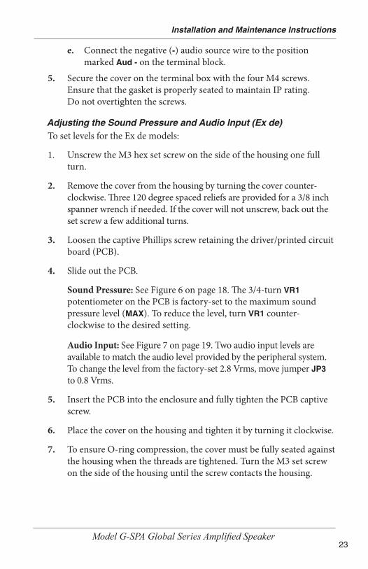
e. Connect the negative (-) audio source wire to the position marked Aud - on the terminal block.
5. Secure the cover on the terminal box with the four M4 screws. Ensure that the gasket is properly seated to maintain IP rating. Do not overtighten the screws.
Adjusting the Sound Pressure and Audio Input (Ex de)To set levels for the Ex de models:
1. Unscrew the M3 hex set screw on the side of the housing one full turn.
2. Remove the cover from the housing by turning the cover counter-clockwise. Three 120 degree spaced reliefs are provided for a 3/8 inch spanner wrench if needed. If the cover will not unscrew, back out the set screw a few additional turns.
3. Loosen the captive Phillips screw retaining the driver/printed circuit board (PCB).
4. Slide out the PCB.
Sound Pressure: See Figure 6 on page 18. The 3/4-turn VR1 potentiometer on the PCB is factory-set to the maximum sound pressure level (MAX). To reduce the level, turn VR1 counter-clockwise to the desired setting.
Audio Input: See Figure 7 on page 19. Two audio input levels are available to match the audio level provided by the peripheral system. To change the level from the factory-set 2.8 Vrms, move jumper JP3 to 0.8 Vrms.
5. Insert the PCB into the enclosure and fully tighten the PCB captive screw.
6. Place the cover on the housing and tighten it by turning it clockwise.
7. To ensure O-ring compression, the cover must be fully seated against the housing when the threads are tightened. Turn the M3 set screw on the side of the housing until the screw contacts the housing.

24
Installation and Maintenance Instructions
Model G-SPA Global Series Amplified Speaker
Safety Messages to Maintenance Personnel
Listed below are some important safety instructions and precautions you should follow:
• Read and understand all instructions before operating this system.
• Repair of flamepaths is not recommended.
• If you acquired a significant quantity of units, it is recommended that spares are also made available.
• To avoid electrical shock hazards, do not connect wires when power is applied. Failure to observe this warning may lead to serious injury or death.
• Any maintenance to the amplified speaker system must be performed by a trained electrician who is thoroughly familiar with all applicable national and local codes in the country of use.
• Any maintenance to the amplified speaker system must be done with power turned off.
• Check the amplified speaker periodically to ensure that the effectiveness of the device has not been reduced because it has been clogged with a foreign substance or because objects have been placed in front of it.
• Never alter the unit in any manner. Safety of the unit may be affected if additional openings or other alterations are made to the internal components or housing.
• The nameplate, which may contain cautionary or other information of importance to maintenance personnel, should NOT be obscured in any way. Ensure that the nameplate remains readable.
• After performing any maintenance, test the amplified speaker system to ensure that it is operating properly.
Failure to follow all safety precautions and instructions may result in property damage, serious injury, or death.

25
Installation and Maintenance Instructions
Model G-SPA Global Series Amplified Speaker
Maintaining the Amplified Speaker
EXPLOSION HAZARD: To prevent ignition of hazardous atmosphere, disconnect the amplified speaker from the supply circuit before opening it. Do not open the amplified speaker in the presence of explosive gases in the atmosphere. Failure to follow this warning may result in serious injury or death.
During the working life of the amplified speaker, it should require little or no maintenance. The non-metallic housing will resist attack by most acids, alkalis, and chemicals and is as resistant to concentrated acids and alkalis as most metal products. However, if abnormal or unusual environment conditions occur due to plant damage or accident, etc., visual inspection of the amplified speaker is recommended.
Cleaning the EnclosureThe enclosure should be cleaned periodically with a damp cloth to maintain maximum sound output. Periodic checks should be made to ensure the effectiveness of this device has not been reduced because the amplified speaker has become clogged with a foreign substance or because objects have been placed in front of the amplified speaker.
Lubricating the Threaded JointsA silicone based, non-hardening, chemically compatible grease can be applied if required.
Ordering Replacement Parts and AccessoriesReplacement parts and accessories are listed in Table 1 below and 2 page 26. Due to certification, certain component parts are not available for field replacement. Amplified speakers with this type of damage must be either replaced entirely or returned to Federal Signal for service. Refer to instruction manual 25500259 for accessory and replacement part assembly and operating instructions. To order, call Federal Signal Customer Support at 708-534-4756 or 877-289-3246.
Table 1 Replacement part
Description Part NumberDriver/PCB Assembly K859501403
26
Installation and Maintenance Instructions
Model G-SPA Global Series Amplified Speaker
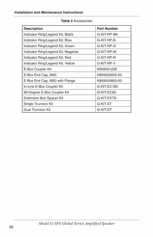
Table 2 Accessories
Description Part NumberIndicator Ring/Legend Kit, Black G-KIT-RP-BKIndicator Ring/Legend Kit, Blue G-KIT-RP-BIndicator Ring/Legend Kit, Green G-KIT-RP-GIndicator Ring/Legend Kit, Magenta G-KIT-RP-MIndicator Ring/Legend Kit, Red G-KIT-RP-RIndicator Ring/Legend Kit, Yellow G-KIT-RP-YE-Box Coupler Kit K859501228E-Box End Cap, M20 K859500805-02E-Box End Cap, M20 with Flange K859500805-03In-Line E-Box Coupler Kit G-KIT-EC18090-Degree E-Box Coupler Kit G-KIT-EC90Extension Box Spacer Kit G-KIT-EXTBSingle Trunnion Kit G-KIT-STDual Trunnion Kit G-KIT-DT
27
Installation and Maintenance Instructions
Model G-SPA Global Series Amplified Speaker
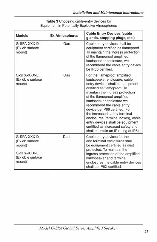
Table 3 Choosing cable-entry devices for Equipment in Potentially Explosive Atmospheres
Models Ex Atmospheres Cable Entry Devices (cable glands, stopping plugs, etc.)
G-SPA-XXX-D(Ex db surface mount)
Gas Cable entry devices shall be equipment certified as flameproof. To maintain the ingress protection of the flameproof amplified loudspeaker enclosure, we recommend the cable entry device be IP66 certified.
G-SPA-XXX-E(Ex db e surface mount)
Gas For the flameproof amplified loudspeaker enclosure, cable entry devices shall be equipment certified as flameproof. To maintain the ingress protection of the flameproof amplified loudspeaker enclosure we recommend the cable entry device be IP66 certified. For the increased safety terminal enclosures (terminal boxes), cable entry devices shall be equipment certified as increased safety and shall maintain an IP rating of IP54.
G-SPA-XXX-D(Ex db surface mount)
G-SPA-XXX-E(Ex db e surface mount)
Dust Cable entry devices for the and terminal enclosures shall be equipment certified as dust protected. To maintain the ingress protection of the amplified loudspeaker and terminal enclosures the cable entry devices shall be IP6X certified.

28
Installation and Maintenance Instructions
Model G-SPA Global Series Amplified Speaker
Getting Technical Assistance or Repair ServiceThe Federal Signal Factory provides technical assistance with any problems that cannot be handled locally. Any unit returned to federal Signal for service, inspection, or repair must be accompanied by a return Material authorization (RMA). Obtain an RMA from a local distributor or manufacturer’s representative. Please provide a brief explanation of the service requested or the nature of the malfunction.
For technical support and service, please visit:
https://www.fedsig.com/Technical-Support
https://www.fedsig.com/Service-Centers