model - furnituredealer.net · espaÑol.....21 model ker222 - 3 - read and save these instructions...
TRANSCRIPT

- 1 -
BEST BY BROAN P.O. Box 140 Hartford, WI 53027
ENGLISH......................................3FRANÇAIS.................................12ESPAÑOL...................................21
Model KER222
- 3 -
READ AND SAVE THESE INSTRUCTIONS
WARNINGTO REDUCE THE RISK OF FIRE, ELECTRIC SHOCK, OR INJURY TO PERSONS,OBSERVE THE FOLLOWING:1. Use this unit only in the manner intended by the manufacturer. If you have questions,
contact the manufacturer at the address or telephone number listed in the warranty.2. Before servicing or cleaning unit, switch power off at service panel and lock service
panel to prevent power from being switched on accidentally. When the servicedisconnecting means cannot be locked, securely fasten a prominent warning device,such as a tag, to the service panel.
3. Installation work and electrical wiring must be done by a qualified person(s) in accor-dance with all applicable codes and standards, including fire-rated construction codesand standards.
4. Sufficient air is needed for proper combustion and exhausting of gases through the flue(chimney) of fuel burning equipment to prevent backdrafting. Follow the heating equip-ment manufacturer’s guidelines and safety standards such as those published by theNational Fire Protection Association (NFPA), and the American Society for Heating,Refrigeration and Air Conditioning Engineers (ASHRAE), and the local code authorities.
5. When cutting or drilling into wall or ceiling, do not damage electrical wiring and otherhidden utilities.
6. Ducted fans must always be vented to the outdoors.7. Do not use this unit with any separate solid-state speed control device.8. To reduce the risk of fire, use only metal ductwork.9. This unit must be grounded.
TO REDUCE THE RISK OF A RANGE TOP GREASE FIRE:A. Never leave surface units unattended at high settings. Boilovers cause smoking and
greasy spillovers that may ignite. Heat oils slowly on low or medium settings.B. Always turn hood ON when cooking at high heat or when flambeing food (i.e. Crepes
Suzette, Cherries Jubilee, Peppercorn Beef Flambe’).C. Clean ventilating fans frequently. Grease should not be allowed to accumulate on fan or
filter.D. Use proper pan size. Always use cookware appropriate for the size of the surface
element.
WARNINGTO REDUCE THE RISK OF INJURY TO PERSONS IN THE EVENT OF A RANGE TOPGREASE FIRE, OBSERVE THE FOLLOWING:*1. SMOTHER FLAMES with a close-fitting lid, cookie sheet, or metal tray, then turn off the
burner. BE CAREFUL TO PREVENT BURNS. If the flames do not go out immediately,EVACUATE AND CALL THE FIRE DEPARTMENT.
2. NEVER PICK UP A FLAMING PAN - You may be burned.3. DO NOT USE WATER, including wet dishcloths or towels - violent steam explosion will
result.4. Use an extinguisher ONLY if:
A. You know you have a Class ABC extinguisher and you already know how to operateit.
B. The fire is small and contained in the area where it started.C. The fire department is being called.D. You can fight the fire with your back to an exit.* Based on “Kitchen Fire Safety Tips” published by NFPA.
! INTENDED FOR DOMESTIC COOKING ONLY !
- 4 -
! CAUTION1. To reduce risk of fire and to properly exhaust air, be sure to duct air outside. Do not vent
exhaust air into spaces within walls or ceilings or into attics, crawl spaces, or garages.2. Take care when using cleaning agents or detergents.3. Avoid using food products that produce flames under the Range Hood.4. For general ventilating use only. Do not use to exhaust hazardous or explosive mate-
rials and vapors.5. To avoid motor bearing damage and noisy and/or unbalanced impellers, keep drywall
spray, construction dust, etc. off power unit.6. Your hood motor has a thermal overload which will automatically shut off the motor if it
becomes overheated. The motor will restart when it cools down. If the motor continuesto shut off and restart, have the hood serviced.
7. For best capture of cooking impurities, the bottom of the hood should be a minimum of24" and a maximum of 30" above the cooking surface.
8. Two installers are recommended because of the large size and weight of this hood.9. This product is equipped with a thermostat which may start blower automatically. To
reduce the risk of injury and to prevent power from being switched on accidentally,switch power off at service panel and lock or tag service panel.
10. Use with approved cord-connection kit only.11. Please read specification label on product for further information and requirements.

- 5 -
PREPARE THE HOODUnpack hood and check contents.You should receive:1 - Hood1 - Decorative Flue Assembly1 - Flue Mounting Bracket1 - Parts Bag (B080810601) containing:
2 - Mounting Brackets8 - Mounting Screws (4,8x38mm Pan
Head)4 - Mounting Screws (3,9x9,5mm Pan
Head)4 - Mounting Screws (3,9x9,5mm Pan
Head Black)8 - Drywall Anchors
1 - Parts Bag (B080810321) containing:2 - Side Ladle-Bars2 - End Bits of the Ladle-Bars2 - Mounting Screws (M8 x 14mm)1 - Key
1 - Installation Instructions1 - Warranty Card
MOUNTINGBRACKETS
FLUE MOUNTINGBRACKET
8 MOUNTINGSCREWS (4,8 x38mm Pan Head)
8 DRYWALLANCHORS
4 MOUNTINGSCREWS (3,9 x 9,5mmPan Head)
DECORATIVEFLUE
4 MOUNTINGSCREWS (3,9 x 9,5mmPan Head - Black)
SIDE LADLE-BARS
END BITS OFTHE LADLE-BARS
2 MOUNTINGSCREWS(M8x14mm)
KEY
- 6 -
DECORATIVEFLUE
WALL
CAP
ROOF CAP
8” ROUND DUCT
8” ROUNDELBOW
HOOD
24” TO 30” ABOVECOOKING SURFACE
B B
M
C
LADLE BAREND BITS
LOWER PART OFTHE HOOD
A
A
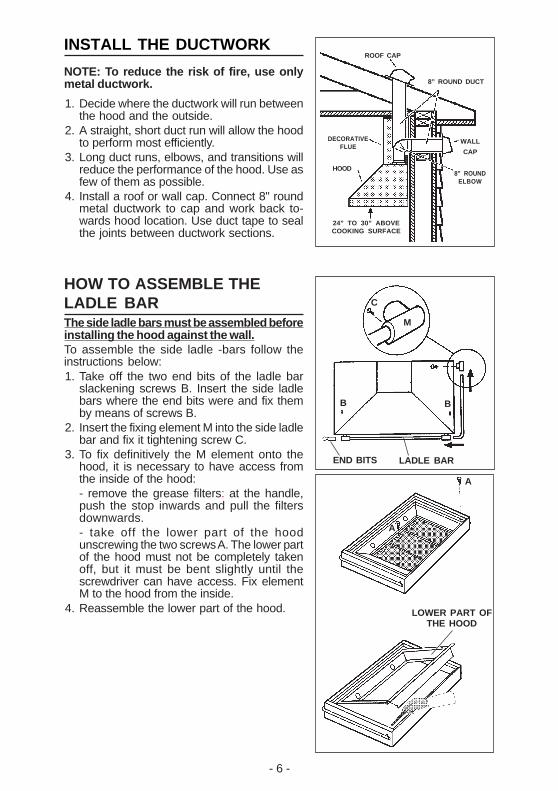
INSTALL THE DUCTWORK
NOTE: To reduce the risk of fire, use onlymetal ductwork.
1. Decide where the ductwork will run betweenthe hood and the outside.
2. A straight, short duct run will allow the hoodto perform most efficiently.
3. Long duct runs, elbows, and transitions willreduce the performance of the hood. Use asfew of them as possible.
4. Install a roof or wall cap. Connect 8" roundmetal ductwork to cap and work back to-wards hood location. Use duct tape to sealthe joints between ductwork sections.
HOW TO ASSEMBLE THELADLE BARThe side ladle bars must be assembled beforeinstalling the hood against the wall.To assemble the side ladle -bars follow theinstructions below:1. Take off the two end bits of the ladle bar
slackening screws B. Insert the side ladlebars where the end bits were and fix themby means of screws B.
2. Insert the fixing element M into the side ladlebar and fix it tightening screw C.
3. To fix definitively the M element onto thehood, it is necessary to have access fromthe inside of the hood:- remove the grease filters: at the handle,push the stop inwards and pull the filtersdownwards.- take off the lower part of the hoodunscrewing the two screws A. The lower partof the hood must not be completely takenoff, but it must be bent slightly until thescrewdriver can have access. Fix elementM to the hood from the inside.
4. Reassemble the lower part of the hood.
- 7 -
INSTALL MOUNTINGBRACKETS1. Construct wood wall framing that is flush
with interior surface of wall studs.Make sure:a) the framing is centered over installationlocation.b) the height of the framing will allow themounting brackets to be secured to theframing within the dimensions shown.
2. After wall surface is finished, securemounting brackets to framing usingdimensions shown.
32-11/16” to 38-5/8” above
cooktop
FRAMING BEHIND DRYWALL
VERSION 90cm
9-5/8”
9-5/8”
32-11/16”= bottom of hood 24" above cooktop38-5/8"= bottom of hood 30" above cooktop
INSTALL THE HOOD1. Before mount hood remove the electrical box.2. Hang the hood from the brackets through
the rectangular cut-outs on the back of thehood. Cut-outs are larger than the bracketsto allow for horizontal adjustment.The bottom of the hood should be 24" to 30"above the cooking surface.
3. Height adjustment screws provide verticaladjustment.
34-7/16” to 40-7/16” above
cooktop
FRAMING BEHIND DRYWALL
VERSION 48”
34-7/16”= bottom of hood 24" above cooktop40-7/16”= bottom of hood 30" above cooktop
33-15/16” to 39-15/16” above
cooktop
FRAMING BEHIND DRYWALLVERSION 42”
9-15/16”
9-15/16”
8-7/8”
8-7/8”
33-15/16”= bottom of hood 24" above cooktop39-15/16"= bottom of hood 30" above cooktop
Note: minimun hood distance above cook top must not be less than 24”. A maximumof 30” above cook top is highly recommended for best capture of cooking impurities.Distances over 30” are at the installer and users discretion; and if ceiling height andflue length permit.
HOODWIDTH
90CM
42”
HOOD DISTANCE ABOVE 36” HIGH COOK TOP24” 25” 26” 27” 28” 29” 30”
BRACKET LOCATION ABOVE 36” COOK TOP29-13/16” 30-13/16” 31-13/16”
48”
CEILINGHEIGHT
8 FEET
DIM.“A”
9-5/8”9 FEET N / A 31-13/16”
32-13/16”
32-13/16”
33-13/16”33-13/16”
N / A
34-13/16” 35-13/16”
8 FEET
9 FEET9-15/16”
N / A
N / A31-1/16” 32-1/16” 33-1/16”
33-1/16”
34-1/16”
34-1/16”
35-1/16”35-1/16” 36-1/16” 37-1/16”
8-7/8”8 FEET
9 FEET N / A
N / A31-9/16” 32-9/16” 33-9/16”
33-9/16”
34-9/16”
34-9/16”
35-9/16”35-9/16” 36-9/16” 37-9/16”
REMOVE THE ELECTRICAL BOX
- 8 -
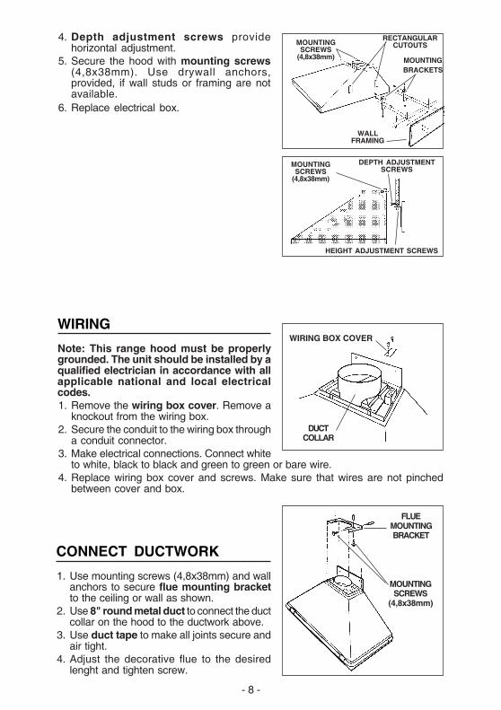
CONNECT DUCTWORK
1. Use mounting screws (4,8x38mm) and wallanchors to secure flue mounting bracketto the ceiling or wall as shown.
2. Use 8" round metal duct to connect the ductcollar on the hood to the ductwork above.
3. Use duct tape to make all joints secure andair tight.
4. Adjust the decorative flue to the desiredlenght and tighten screw.
FLUEMOUNTINGBRACKET
MOUNTINGSCREWS
(4,8x38mm)
WIRING
Note: This range hood must be properlygrounded. The unit should be installed by aqualified electrician in accordance with allapplicable national and local electricalcodes.1. Remove the wiring box cover. Remove a
knockout from the wiring box.2. Secure the conduit to the wiring box through
a conduit connector.3. Make electrical connections. Connect white
to white, black to black and green to green or bare wire.4. Replace wiring box cover and screws. Make sure that wires are not pinched
between cover and box.
WIRING BOX COVER
DUCTCOLLAR
HEIGHT ADJUSTMENT SCREWS
DEPTH ADJUSTMENTSCREWS
MOUNTINGSCREWS
(4,8x38mm)
WALLFRAMING
MOUNTINGBRACKETS
RECTANGULARCUTOUTSMOUNTING
SCREWS(4,8x38mm)
4. Depth adjustment screws providehorizontal adjustment.
5. Secure the hood with mounting screws(4,8x38mm). Use drywall anchors,provided, if wall studs or framing are notavailable.
6. Replace electrical box.
- 9 -
MAINTENANCE
Proper maintenance of the Range Hood willassure proper performance of the unit.
Grease FiltersThe grease filters should be cleaned fre-quently. Use a warm detergent solution. Greasefilters are dishwasher safe.To take off the grease filters: at the handle, pushthe stop inwards and pull the filters downwards.
Hood CleaningStainless steel is one of the easiest materials to keep clean. Occasional care willhelp preserve its fine appearance.Cleaning tips:● Hot water with soap or detergent is all that is usually needed.● Follow all cleaning by rinsing with clear water. Wipe dry with a clean, soft cloth to
avoid water marks.● For discolorations or deposits that persist, use a non-scratching household cleanser
or stainless steel polishing powder with a little water and a soft cloth.● For stubborn cases, use a plastic scouring pad or soft bristle brush together with
cleaser and water. Rub lightly in direction of polishing lines or "grain" of thestainless finish. Avoid using too much pressure which may mar the surface.
● DO NOT allow deposits to remain for long periods of time.● DO NOT use ordinary steel wool or steel brushes. Small bits of steel may adhere
to the surface causing rust.● DO NOT allow salt solutions, disinfectants, bleaches, or cleaning compounds to
remain in contact with stainless steel for extended periods. Many of these com-pounds contain chemicals which may be harmful. Rinse with water after expo-sure and wipe dry with a clean cloth.
Painted surfaces should be cleaned with warm water and mild detergent only.
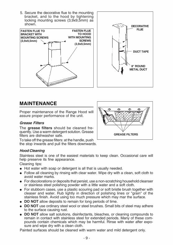
GREASE FILTERS
8" ROUNDMETAL DUCT
DUCT TAPE
DECORATIVEFLUEFASTEN FLUE
TO HOODWITH MOUNTING
SCREWS(3,9x9,5mm)
FASTEN FLUE TOBRACKET WITHMOUNTING SCREWS(3,9x9,5mm)
5. Secure the decorative flue to the mountingbracket, and to the hood by tighteninglocking mounting screws (3,9x9,5mm) asshown.
- 10 -
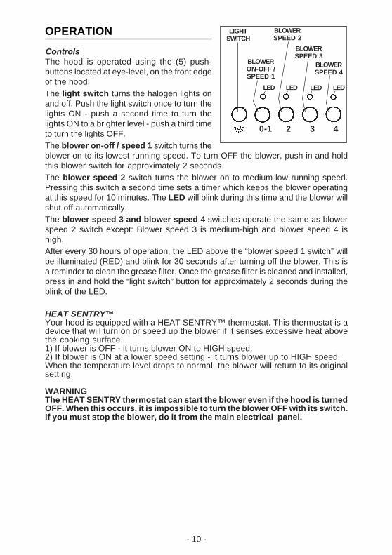
OPERATION
ControlsThe hood is operated using the (5) push-buttons located at eye-level, on the front edgeof the hood.The light switch turns the halogen lights onand off. Push the light switch once to turn thelights ON - push a second time to turn thelights ON to a brighter level - push a third timeto turn the lights OFF.The blower on-off / speed 1 switch turns theblower on to its lowest running speed. To turn OFF the blower, push in and holdthis blower switch for approximately 2 seconds.The blower speed 2 switch turns the blower on to medium-low running speed.Pressing this switch a second time sets a timer which keeps the blower operatingat this speed for 10 minutes. The LED will blink during this time and the blower willshut off automatically.The blower speed 3 and blower speed 4 switches operate the same as blowerspeed 2 switch except: Blower speed 3 is medium-high and blower speed 4 ishigh.After every 30 hours of operation, the LED above the “blower speed 1 switch” willbe illuminated (RED) and blink for 30 seconds after turning off the blower. This isa reminder to clean the grease filter. Once the grease filter is cleaned and installed,press in and hold the “light switch” button for approximately 2 seconds during theblink of the LED.
HEAT SENTRY™Your hood is equipped with a HEAT SENTRY™ thermostat. This thermostat is adevice that will turn on or speed up the blower if it senses excessive heat abovethe cooking surface.1) If blower is OFF - it turns blower ON to HIGH speed.2) If blower is ON at a lower speed setting - it turns blower up to HIGH speed.When the temperature level drops to normal, the blower will return to its originalsetting.
WARNINGThe HEAT SENTRY thermostat can start the blower even if the hood is turnedOFF. When this occurs, it is impossible to turn the blower OFF with its switch.If you must stop the blower, do it from the main electrical panel.
BLOWERON-OFF /SPEED 1
0-1 2 3 4
LED LED LED LED
BLOWERSPEED 4
LIGHTSWITCH
BLOWERSPEED 2
BLOWERSPEED 3
- 11 -
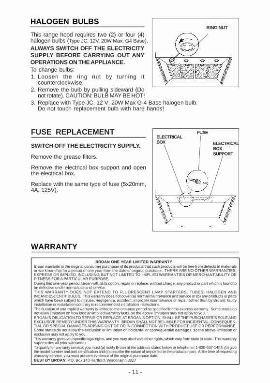
FUSE REPLACEMENT
SWITCH OFF THE ELECTRICITY SUPPLY.
Remove the grease filters.
Remove the electrical box support and openthe electrical box.
Replace with the same type of fuse (5x20mm,4A, 125V).
ELECTRICALBOXSUPPORT
FUSEELECTRICALBOX
WARRANTY
BROAN ONE YEAR LIMITED WARRANTYBroan warrants to the original consumer purchaser of its products that such products will be free from defects in materialsor workmanship for a period of one year from the date of original purchase. THERE ARE NO OTHER WARRANTIES,EXPRESS OR IMPLIED, INCLUDING, BUT NOT LIMITED TO, IMPLIED WARRANTIES OR MERCHANT ABILITY ORFITNESS FOR A PARTICULAR PURPOSE.During this one-year period, Broan will, at its option, repair or replace, without charge, any product or part which is found tobe defective under normal use and service.THIS WARRANTY DOES NOT EXTEND TO FLUORESCENT LAMP STARTERS, TUBES, HALOGEN ANDINCANDESCENDT BULBS. This warranty does not cover (a) normal maintenance and service or (b) any products or partswhich have been subject to misuse, negligence, accident, improper maintenance or repair (other than by Broan), faultyinstallation or installation contrary to recommended installation instructions.The duration of any implied warranty is limited to the one-year period as specified for the express warranty. Some states donot allow limitation on how long an implied warranty lasts, so the above limitation may not apply to you.BROAN’S OBLIGATION TO REPAIR OR REPLACE, AT BROAN’S OPTION, SHALL BE THE PURCHASER’S SOLE ANDEXCLUSIVE REMEDY UNDER THIS WARRANTY. BROAN SHALL NOT BE LIABLE FOR INCIDENTAL, CONSEQUEN-TIAL OR SPECIAL DAMAGES ARISING OUT OF OR IN CONNECTION WITH PRODUCT USE OR PERFORMANCE.Some states do not allow the exclusion or limitation of incidental or consequential damages, so the above limitation orexclusion may not apply to you.This warranty gives you specific legal rights, and you may also have other rights, which vary from state to state. This warrantysupersedes all prior warranties.To qualify for warranty service, you must (a) notify Broan at the address stated below or telephone: 1-800-637-1453, (b) givethe model number and part identification and (c) describe the nature of any defect in the product or part. At the time of requestingwarranty service, you must present evidence of the original purchase date.BEST BY BROAN, P.O. Box 140 Hartford, Wisconsin 53027
HALOGEN BULBS
This range hood requires two (2) or four (4)halogen bulbs (Type JC, 12V, 20W Max, G4 Base).ALWAYS SWITCH OFF THE ELECTRICITYSUPPLY BEFORE CARRYING OUT ANYOPERATIONS ON THE APPLIANCE.To change bulbs:1. Loosen the ring nut by turning it
counterclockwise.2. Remove the bulb by pulling sideward (Do
not rotate). CAUTION: BULB MAY BE HOT!3. Replace with Type JC, 12 V, 20W Max G-4 Base halogen bulb.
Do not touch replacement bulb with bare hands!
RING NUT
- 30 -
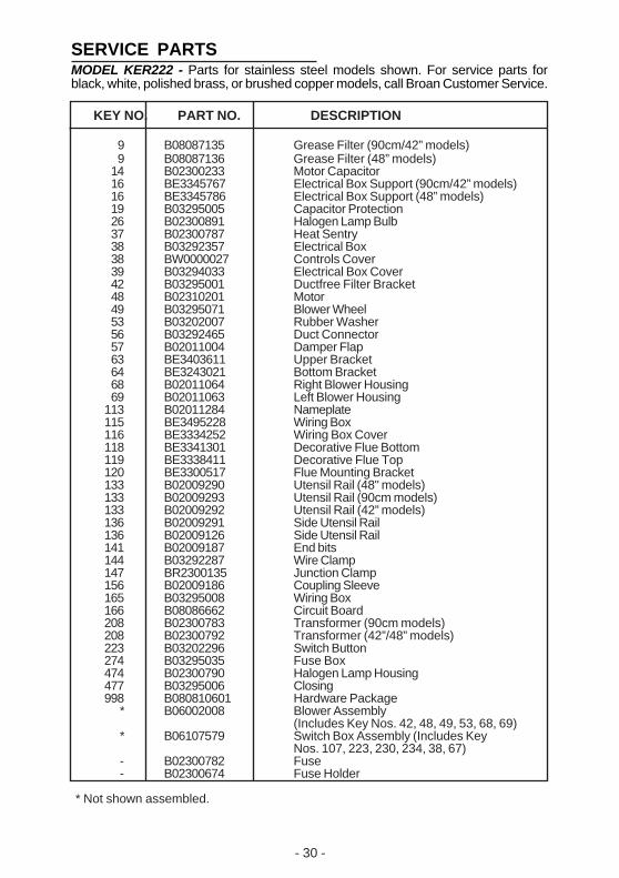
SERVICE PARTSMODEL KER222 - Parts for stainless steel models shown. For service parts forblack, white, polished brass, or brushed copper models, call Broan Customer Service.
KEY NO. PART NO. DESCRIPTION
9 B08087135 Grease Filter (90cm/42” models)9 B08087136 Grease Filter (48” models)
14 B02300233 Motor Capacitor16 BE3345767 Electrical Box Support (90cm/42” models)16 BE3345786 Electrical Box Support (48” models)19 B03295005 Capacitor Protection26 B02300891 Halogen Lamp Bulb37 B02300787 Heat Sentry38 B03292357 Electrical Box38 BW0000027 Controls Cover39 B03294033 Electrical Box Cover42 B03295001 Ductfree Filter Bracket48 B02310201 Motor49 B03295071 Blower Wheel53 B03202007 Rubber Washer56 B03292465 Duct Connector57 B02011004 Damper Flap63 BE3403611 Upper Bracket64 BE3243021 Bottom Bracket68 B02011064 Right Blower Housing69 B02011063 Left Blower Housing
113 B02011284 Nameplate115 BE3495228 Wiring Box116 BE3334252 Wiring Box Cover118 BE3341301 Decorative Flue Bottom119 BE3338411 Decorative Flue Top120 BE3300517 Flue Mounting Bracket133 B02009290 Utensil Rail (48" models)133 B02009293 Utensil Rail (90cm models)133 B02009292 Utensil Rail (42” models)136 B02009291 Side Utensil Rail136 B02009126 Side Utensil Rail141 B02009187 End bits144 B03292287 Wire Clamp147 BR2300135 Junction Clamp156 B02009186 Coupling Sleeve165 B03295008 Wiring Box166 B08086662 Circuit Board208 B02300783 Transformer (90cm models)208 B02300792 Transformer (42”/48” models)223 B03202296 Switch Button274 B03295035 Fuse Box474 B02300790 Halogen Lamp Housing477 B03295006 Closing998 B080810601 Hardware Package
* B06002008 Blower Assembly(Includes Key Nos. 42, 48, 49, 53, 68, 69)
* B06107579 Switch Box Assembly (Includes KeyNos. 107, 223, 230, 234, 38, 67)
- B02300782 Fuse- B02300674 Fuse Holder
* Not shown assembled.

SERVICE PARTS - LISTE PIECES DE RECHANGE -LISTA DE PIEZAS DE RECAMBIOMODEL KER222
- 33 -

04306955/6N