model cs-900 model cs-900-exp control station … · user's instruction manual (version 3.0)...
TRANSCRIPT
Connect Systems Inc. - Model CS-900 Page 1
CONNECT SYSTEMS INCORPORATED1802 Eastman Ave. Suite 116
Ventura, Ca. 93003
Phone (805) 642-7184Fax (805) 642-7271
Model CS-900&
Model CS-900-EXP
CONTROL STATION INTERCONNECT
USER'S INSTRUCTION MANUAL(Version 3.0)

Connect Systems Inc. - Model CS-900 Page 2
TABLE OF CONTENTS
Description .................................... 2Installation and Adjustments ................... 3Programming Procedure .......................... 8Operating Mode Programming ..................... 9CW ID Programming .............................. 18Speed Dialer Programming ....................... 19Toll Override Programming ...................... 21Remote programming ............................. 23Operation ...................................... 27Glossary ....................................... 34Warrantee ...................................... 35FCC Notice to Users ............................ 36Schematic Diagrams ........................ 38 - 40Board Layout ................................... 41
OPTIONS:Export Version (Option CS-900-EXP) ... 2, 17, 27, 32Auxiliary Relay (Option 901) ................ 33
-----------------------------------------------------------------
GENERAL DESCRIPTION
Congratulations on your choice of our Model CS-900 Control StationInterconnect. The CS-900 is the only low cost Control StationInterconnect that delivers important standard features such asElectronic Voice Delay (EVD), fully regenerated DTMF dialing, Speed-dialing, Last number redial, Call progress tone detection and more.Additionally, The CS-900 delivers many other essential features suchas the built-in programming keyboard and digital display which are notavailable in any other interconnect on the market today!
******************** CS-900-EXP ONLY ------------------->Segments of this manual which are only applicable to the EXP versionare clearly marked similar to this example. Please ignore if you havea standard CS-900.
The CS-900-EXP (option) has special software to accommodate foreigntelephone systems such as those in eastern Europe. The CS-900-EXPpermits dialing using second (or even third) dialtones, properrecognition of Euro dialtones / busy signals permitting automaticdisconnect and mobile selective calling from a rotary dial pulsetelephone. The latter feature is sometimes known as dial clickdetection and is included in the CS-900-EXP version.
<------------------- CS-900-EXP ONLY ********************
Designed and built with pride in the U.S.A.
Connect Systems Inc. - Model CS-900 Page 3
INSTALLATION AND ADJUSTMENTS
Internal Connections vs External Connections: The CS-900 can beconnected either internally or externally to the base station radio.Internal connections are essential if the radio is also to be used fordispatch operation. External connections to the Mic and speaker jacksare acceptable for dedicated or amateur installations. Some featuressuch as Busy Channel Ringout Inhibit cannot function if the externalhook-up method is chosen. This is because there is no COS connection.
Both internal and external connection methods are presented. Functionsthat will not operate and forced programming choices that must beadhered to if the external connection method is used are notedthroughout this manual.
INTERNAL CONNECTION METHOD (Preferred)
Use shielded wires with the shields at each end connected to chassisground. (The rear panel barrier strip terminals labeled "GND" arechassis ground). We recommend using spade type crimp-on connectors forease and reliability. Connect the center wires as follows:
AUDIO IN: The receiver audio takeoff point can be anywhere from thediscriminator to the high side of the volume control (werecommend connecting to the high side of the volumecontrol in most applications). Be sure to install the de-emphasis strap JP-5 if connecting to the discriminator.Remove JP-5 if connecting beyond the De-emphasis filter.If JP-5 is not properly selected, you may experiencedifficulty with DTMF decoding plus poor mobile to landaudio quality.
COS: The COS input can be connected to the noise squelch forcarrier operation, or to the DPL/CTCSS squelch if youwant the radios' built-in decoder to provide privateoperation.
Noise Squelch Connection: Connect to a point that hasconsiderable voltage swing when the squelch isopened/closed. The best point to connect is to thecollector of the transistor that controls the busy light(if the radio has one). Otherwise, connect to the squelchgate control voltage.
DPL or CTCSS Squelch: The receiver's DPL or CTCSSdecoder will have a logic point that goes high or lowwhen a properly encoded signal is received. Connect thispoint to the COS input.
Connect Systems Inc. - Model CS-900 Page 4
If the point selected goes more positive (voltageincreases) when a signal is received, strap JP-6 centerto the + side. If the point goes to a lower voltage,strap JP-6 from center to the - side.
When the COS threshold control P11 has been properlyadjusted (described below), and JP-6 properly strapped,the front panel REC LED will illuminate when a signal isreceived and go out when the signal goes away. Thiscondition must be achieved for proper operation of theinterconnect.
AUDIO OUT: Connect to the Mic high line. If Mic loading occursinstall a resistor in series with the Audio Out lead, andcut JP-3. The resistor should be large enough to preventMic loading but small enough to achieve adequate land tomobile audio. Try 100K as a first cut.
PTT: Connect to the base station PTT line.
NOTE: Some radios will need the Aux. Relay connected tothe hookswitch before the transmitter can be activated.Others may require positive keying. See 'Auxiliary Relay'page 33 for details.
POWER: Connect to a source of 12-14 VDC that can supply up to100 MA. The CS-900-EXP is reverse polarity protected, soa polarity mistake will not damage your CS-900.
EXTERNAL CONNECTION METHOD (For amateur use only)
Use shielded wires with the shields at each end connected to chassisground. (The rear panel barrier strip terminals labeled "GND" arechassis ground). We recommend using spade type crimp-on connectors forease and reliability. Connect the center wires as follows:
NOTE: Since a COS (Carrier Operated Squelch) connection is not madewhen using the External Connection Method several features which arenot of great importance to Amateur users will not function. Thesefeatures and certain programming steps which must be set asspecified are annotated with a special note labeled... "EXTERNALCONNECTION NOTE:"
AUDIO IN: You must obtain a plug that mates with your radiosspeaker jack. Connect the center wire to the center pinin the speaker jack. Connect the shield to the ground lugof the speaker jack. Be sure that de-emphasis strap JP-5is removed or DTMF will not decode properly.

Connect Systems Inc. - Model CS-900 Page 5
COS: This terminal must be connected to a GND terminal whenusing the external connection method.
Also you must rotate the COS threshold control P11 to midrotation and put the COS polarity select strap JP-6 inthe - position (center pin to - pin). The REC LED must beconstantly illuminated for the external connection methodto operate.
AUDIO OUT: You must obtain a microphone plug that will mate with& your radios microphone jack. You will need to
PTT: identify which pins are used for Mic audio, PTT andGround. Connect the center wire from the AUDIO OUT to theMic Audio pin. Connect the center wire from the PTT pinto the PTT pin in the Mic plug. Connect the shields ofthe two wires to the ground pin in the Mic plug.
WARNING: The PTT switching transistor Q12 can be damagedif you allow the PTT lead to come into contact with ahard voltage source such as 12 VDC. Most Mic jacks have a12 VDC pin which supplies voltage to the DTMF pad in themicrophone. You must be cautious to not incorrectlyconnect the PTT to the wrong pin or to accidentally letthe PTT line come in momentary contact with the 12 VDCpin. Transistor Q12 is specifically not covered bywarranty. Please read WARRANTY on page 34 for details.
POWER: Connect to a source of 12-14 VDC that can supply up to100 MA. The CS-900 is reverse polarity protected, so apolarity mistake will not damage your CS-900.
#################### WARNING ####################
The CS-900 contains a power supply sensing circuit that continuouslymonitors the input supply voltage. An instantaneous drop below 10 VDCwill cause a microcomputer reset. If the power supply has poorregulation, erratic operation may result.
The purpose of the input voltage sensor is to protect the non volatileEE memory during power up and power down.
If erratic operation such as losing calls occurs, be suspicious ofpoor regulation from the power supply.
#########################################################

Connect Systems Inc. - Model CS-900 Page 6
ADJUSTMENTS
Initial settings: Set P1 fully counterclockwise.Set P4, P5, P9, P10 and P11 to mid rotation.Set P8 fully clockwise.
POT PCB Name Function
P1 M->L: Mobile to land level: Initially adjust untilmobile DTMF decodes as indicated on front panelDTMF LED. Later, adjust for proper mobile levelas heard on telephone.
Note: DTMF will not decode unless the REC LED isilluminated indicating that a signal is beingreceived.
P4 DTMF: Patch to mobile DTMF level: Sets the DTMFtransmitter modulation level of land to mobileselective calling and Ringout DTMF sequence.
Note: P4 has no effect on DTMF dialing level sentto the phone line.
P5 BEEPS/CW ID: Status beeps & CW ID level: Adjust for desiredmodulation level of status beeps or CW ID.
P8 RX VOX: Receiver VOX sensitivity: Sets RX audiotriggering sensitivity. Should be fully CW in VOXsimplex applications. Reduce setting when usedthrough repeaters or trunked systems if land linecannot respond to mobile during hangtime due tonoise or CTCSS on the repeaters' carrier.
P9 TEL VOX: Telephone VOX sensitivity: Sets telephone VOXsensitivity for voice, call progress tonedetection and dial click detection. Adjust tosuit. Mid rotation is about right for mostapplications.
P10 L->M Land to mobile level: Press the C/D(Connect/Disconnect) switch so that a dialtone isheard. Adjust P10 until the dialtone producesabout 3 Khz. of modulationdeviation. Cut JP-3 if required.
P11 COS COS Threshold level: Measure the voltage at TP-1with no signal. Then measure the voltage againwith a signal applied. Adjust P-11 until thevoltage reading at TP-2 is approximately midwaybetween the two readings previously obtained atTP-1.

Connect Systems Inc. - Model CS-900 Page 7
For example: If TP-1 reads 2 volts with nosignal, and 4 volts with a signal applied to thereceiver, TP-2 should be set to read 3 volts.
Important: If JP-6 is properly strapped and P11properly adjusted, the REC LED will beilluminated when a signal is received and shouldbe out when there's no signal.
-----------------------------------------------------------------
JUMPER STRAP OPTIONS
JP-3 Audio output range strap. Strap in = low level (0-1 V). Strapremoved = high level (0-5 V). Strap factory installed. (JP-3 isin front of the Aux. Relay K2)
JP-5 Factory installed. Removal eliminates the built-in de-emphasisnetwork. Remove only if receiver audio is taken past de-emphasis. (e.g. from the volume control or the speaker jack).(JP-5 is just to the right of transformer T1).
JP-6 Selects the proper COS polarity to match your radio. If theselected COS takeoff point goes high when a signal is received,connect the center pad to the + pad. If the COS input goes lowwhen a signal is received, connect the center pad to the - pad.When P11 (COS threshold) is properly adjusted, the REC LED willbe illuminated when a signal is received and will be out whenthere's no signal. (JP-6 is just behind IC U23).
JP-7 Selects whether the Aux. Relay output is normally open (NO) or,normally closed (NC). JP-7 is factory strapped for NO. For NCoperation, connect the center pad to the NC pad. (JP-7 is nearthe RJ-11 phone jack).
JP-9 JP-9 and JP-10 are used to enable / disable line in use& detection. These straps are mutually exclusive. That is to JP-10 say that one or the other must be strapped (but not both atthe same time). The CS-900-EXP is delivered with line in usedetection disabled (JP-9 strapped). To enable line in usedetection remove the plastic push-on clip from JP-9 and re-install on JP-10. (JP-9 is three centimeters to the right ofaux. relay K2. JP-10 is adjacent to the phone jack).
NOTE: There is no JP-1, JP-2, JP-4 or JP-8

Connect Systems Inc. - Model CS-900 Page 8
PROGRAMMING THE CS-900
The CS-900 has four easily-accessed programming areas: OperatingParameters, CW ID, Speed-Dial Phone Numbers and Toll OverrideSelections. To enter one of the programming areas, turn the power off,press and hold the corresponding programming area button (No. 1 forOperating Parameters, No. 2 for CW ID or No. 3 for Speed-Dial PhoneNumbers, No. 4 for Toll Override Selections) and simultaneously turnon the power. The display will show 0.x., where x is the number of theprogramming button that is being pressed. Release the button, andprogramming may begin.
Each programming area has the following features in common:
1) Programming line numbers are displayed with the dotsilluminated on the displays. e.g. 0.1., 4.5. etc.
2) Data values are displayed without the dots illuminated. e.g. 00, 30, etc.
3) Data is entered at a line number by pressing the desireddigits followed by the 'P' key. Consider the 'P' key as theenter key.
4) The GOTO Any Address line is displayed as A.A. This lineis used to branch to any line number in the currentprogramming area. For example, the current line is A.A.and you wish to goto line 30. Enter 3 0 P on the keypadand the display will read 3.0.
5) Pressing only P at the A.A. line will advance the lineto 0.1. Pressing only P at any other line will advance tothe next available programming line.
Note: In CW ID, Speed-Dialer and Toll OverrideSelections the next line will be the next numeric linenumber. In Operating Parameters programming, the next lineis often determined by selections made at the current lineand is not necessarily the next numeric line (see the'Programming the Operating Mode and Parameters' section).
6) To view the data at a given line number, briefly press Con the keypad and then release it. The display will thenshow the data for a few seconds and then re-display thecurrent line number. Consider 'C' the data 'see' key.
7) At any point during programming, you may return to the A.A. line by holding down the C key until A.A. appears onthe display (approximately three seconds).
MASTER RESET COMMAND
All user programmable selections in Programming Areas No. 1, 2, 3 and4 can be simultaneously reinitialized to the factory default settingsby simultaneously pressing the 3 and 7 keys on the internal keyboardwhile powering up the CS-900 with the front panel power switch.TO REITERATE, all user programming including Operating Parameters, CWID, Speed-dial phone numbers and Toll Override Selections will be lostif a 3+7 reset is performed!

Connect Systems Inc. - Model CS-900 Page 9
PROGRAMMING THE OPERATING MODE AND PARAMETERS(Programming Area No. 1)
To enter the parameter programming mode, press and hold button No. 1on the internal keypad and then simultaneously turn on the powerswitch. At this point, the display will read 0.1. When you release theNo. 1 button, you will see A.A.
A.A. (GOTO Any Address)Press 'P' to start at line 0.1., or enter the line numberyou wish to go to and then press 'P'. All line numbers and theirassociated parameters are listed below starting with OPERATINGMODE SELECTION.
Viewing or Changing Parameter ValuesA quick tap on 'C' will reveal (for a moment) the currentlyselected parameter of the displayed program line. If theparameter is acceptable, press 'P' to advance to the nextprogram line, or, enter a new parameter and press 'P' toadvance to the next program line.
Parameter CheckingIf an out of range parameter is entered (e.g. 87 on line0.2.) pressing 'P' will not cause an advance to the nextprogram line. This prevents you from accidentally enteringan unusable choice.
Returning to A.A.Programming is finished when you arrive back at A.A. Ifnecessary, you can return to a previously programmed line byholding down 'C' for several seconds. This will return youto A.A. Now enter the line number you wish to return to andpress 'P'. Line sequential programming will always flowforward from the current line.
Line numbers shown in braces e.g. [1.4.], indicate whereprogramming will continue after a selection.
When you finish programming, simply turn the power off, and thenback on to return to the operate mode.

Connect Systems Inc. - Model CS-900 Page 10
OPERATING MODE SELECTION [Branch to]
IMPORTANT: The following four programming lines are not used in theCS-900. Please be sure to leave these lines set with thedefault data values shown or erratic operation to nooperation may result.
0.1. = 10.2. = 850.3. = 30.4. = 9
0.5. RxVOX or Carrier Control1 = RxVOX [0.6.]0 = Carrier [0.7.]DEFAULT: 1 = RxVOX
Select RxVOX for operation through remotely located repeaters orsimplex. Select CARRIER for simplex operation only. In CARRIER,the telephone party cannot key the base transmitter while themobile is talking.
EXTERNAL CONNECTION NOTE: Must be set for 1 = RxVOX if using theexternal connection method.
0.6. Refresh (Also known as Pulser)0 = DisableSelect 1-99 (.1-9.9 seconds).1 sec increments per stepDEFAULT: 0 = Disable
The refresh is normally only used for compatibility with sometrunked systems such as the GE MARC V. Select 0 (disable) if notrequired. Otherwise select a pulse interval just shorter than therepeater hang time. The pulse interval is equal to .1 secondtimes the number entered. A setting of 40 (4 seconds) is aboutright for the GE MARK V.
Note: This parameter has nothing to do with pulse dialing.
0.7. Activity Timer Mode1 = Standby [1.4.]0 = Disconnect [1.4.]DEFAULT: 1 = Standby
Choose how the activity timer operates in VOX mode. In "Standby",landline activity exceeding the timer limit drops the patch intostand-by (off the air). Pressing * in the mobile restores normaloperation. Select "Disconnect" if you prefer the patch todisconnect upon exceeding the activity limit. (The activity timeis set at line 2.6.)
Connect Systems Inc. - Model CS-900 Page 11
IMPORTANT: The following six programming lines are not used in theCS-900. Please be sure to leave these lines set with thedefault data values shown or erratic operation to nooperation may result.
0.8. = 00.9. = 01.0. = 4561.1. = 301.2. = 301.3. = 30
OUTGOING CALLS
1.4. Connect Code0 = * Upx - xxxx = Multi Digit AccessProtocol: *xxxxDEFAULT: 0 = * up
Selects the phone patch access code. Enter 0 for * up operation.Otherwise enter a one to four digit code. To access the patchpress * plus the selected code. (e.g. You want the access code tobe *387. Simply enter 387 P on the keyboard).
1.5. Secret Toll Override Codex - xxxx = Multi Digit OverrideProtocol: *xxxxDEFAULT: 1234
This is a separate secret code that overrides the programmed tollprotection selected on lines 2.0. through 2.5. The access code(1.4.), and the secret toll override code cannot start with thesame sequence. e.g. An access code of *2 would not be compatiblewith a secret code of *2567. Select codes that are distinctlydifferent, such as Access Code = *56 and Secret Code = *3927.
Note: The secret Toll Override Code is inoperable if * up isselected on 1.4. At least one additional digit must beprogrammed, such as *7, *1 etc.
1.6. Disconnect Code0 = # Down1 = # Plus Connect CodeDEFAULT: 0 = # Down
Choose the patch disconnect code. Enter 0 to select # down inmost applications. Or enter 1 to select # plus the connect codedigits that were selected on line 1.4.

Connect Systems Inc. - Model CS-900 Page 12
1.7. Five PTT Autodial1 = Enable0 = DisableDEFAULT: 0 = Disable
If enabled, five presses of the mobile Mic button (at about onepress second) will automatically dial the phone number stored inspeed dialer memory location No.1. Five subsequent presses willcause a disconnect.
EXTERNAL CONNECTION NOTE: This feature can not operate without aninternal COS connection to the receiver.
1.8. Dialing Mode1 = Tone0 = PulseDEFAULT: 1 = Tone
Select how the CS-900 will dial your phone calls. Note that toneis much faster if you are in a touch-tone telephone exchange.(The DTMF tone is fully regenerated).
1.9. Access DelaySelect 1-9 (1-9 seconds)1 sec increments per stepDEFAULT: 3 = 3 secsAccess delay is a user selectable delay to compensate for PTThang after pressing a DTMF key on mobile and portable radios.Select a value that allows you to hear all of the CW ID and/ordialtone without clipping.
2.0. Manual Dialing1 = Enable [2.1.]0 = Disable [2.6.]DEFAULT: 1 = Enable
Select disable if dialing should only be allowed from the speeddialer memory.
2.1. Toll Restrict Digit Counting1 = Enable0 = DisableDEFAULT: 0 = Disable
Enables/disables toll restrict digit counting. If enabled, anumber exceeding ten digits cannot be dialed.
2.2. Prefix Restrict A0000 = None (display reads ' -')x - xxxx = Multi Digit Prefix RestrictionDEFAULT: 1 = 'One' Digit Prefix Restriction (Long Distance)
A 'one' may only be set on this line in order for toll override1-800 dialing to operate.

Connect Systems Inc. - Model CS-900 Page 13
2.3. Prefix Restrict B0000 = None (display reads ' -')x - xxxx = Multi Digit Prefix RestrictionDEFAULT: 0 = 'Zero' Digit Prefix Restriction (Operator)
2.4. Prefix Restrict C0000 = None (display reads ' -')x - xxxx = Multi Digit Prefix Restriction (e.g. 976)DEFAULT: - = None
2.5. Prefix Restrict D0000 = Nonex - xxxx = Multi Digit Prefix Restriction (e.g. 411)DEFAULT: - = None
Lines 2.2., 2.3., 2.4., and 2.5. allow selecting any four singledigit or multi-digit sequences as restricted. Four digits insequence maximum. e.g. to restrict 0 (operator), 1 (longdistance), 976 and 411 enter 0 on line 2.2., enter 1 on line2.3., enter 976 on line 2.4. and enter 411 on line 2.5.
NOTE: In programming area No. 4 you may create up to ten TollOverride Selections which allow you to have the protection oftoll restriction, but allow you to dial specific area codes,portions of an area code or specific phone numbers. See page 21.
2.6. Activity Timer0 = DefeatSelect 10-99 (10-99 seconds)1 sec increments per stepDEFAULT: 30 = 30 secs
Enter the patch activity timer time directly in seconds or enter0 to defeat. The activity timer is reset by pressing the Micbutton in sampling or duplex mode. Or by pressing * in VOX modebut only if you entered a 1 on line 0.7.
2.7. Timeout Timer0 = DefeatSelect 1-99 (.5-49.5 minutes).5 minute increments per stepDEFAULT: 6 = 3 minutes
Select the maximum call limit time. The time is equal to .5minutes (30 seconds) times the number you enter.
2.8. CW ID1 = CW ID at connect and disconnect.0 = CW ID at disconnect only.DEFAULT: 0 = At disconnect only.
After accessing, manual dialing and auto-dialing are delayeduntil the CW ID is finished if you enter 1.
Connect Systems Inc. - Model CS-900 Page 14
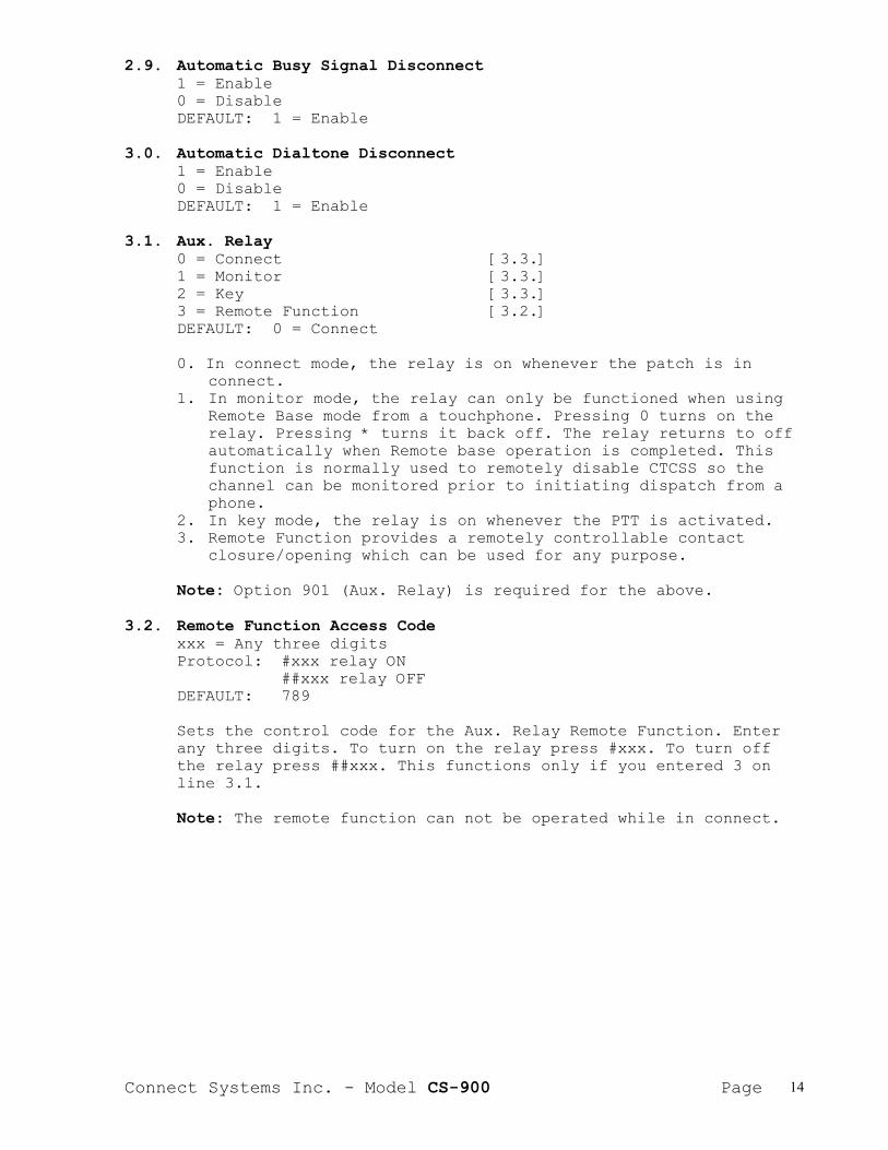
2.9. Automatic Busy Signal Disconnect1 = Enable0 = DisableDEFAULT: 1 = Enable
3.0. Automatic Dialtone Disconnect1 = Enable0 = DisableDEFAULT: 1 = Enable
3.1. Aux. Relay0 = Connect [3.3.]1 = Monitor [3.3.]2 = Key [3.3.]3 = Remote Function [3.2.]DEFAULT: 0 = Connect
0. In connect mode, the relay is on whenever the patch is inconnect.
1. In monitor mode, the relay can only be functioned when usingRemote Base mode from a touchphone. Pressing 0 turns on therelay. Pressing * turns it back off. The relay returns to offautomatically when Remote base operation is completed. Thisfunction is normally used to remotely disable CTCSS so thechannel can be monitored prior to initiating dispatch from aphone.
2. In key mode, the relay is on whenever the PTT is activated.3. Remote Function provides a remotely controllable contact
closure/opening which can be used for any purpose.
Note: Option 901 (Aux. Relay) is required for the above.
3.2. Remote Function Access Codexxx = Any three digitsProtocol: #xxx relay ON
##xxx relay OFFDEFAULT: 789
Sets the control code for the Aux. Relay Remote Function. Enterany three digits. To turn on the relay press #xxx. To turn offthe relay press ##xxx. This functions only if you entered 3 online 3.1.
Note: The remote function can not be operated while in connect.
Connect Systems Inc. - Model CS-900 Page 15
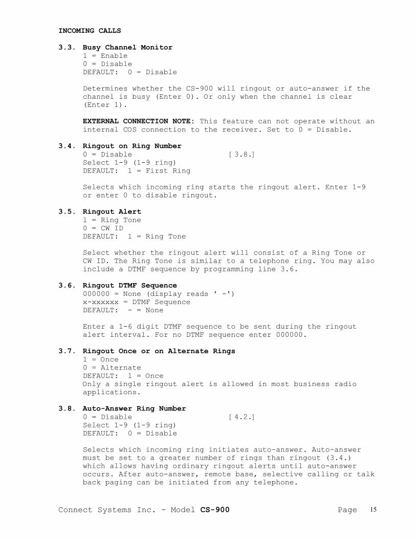
INCOMING CALLS
3.3. Busy Channel Monitor1 = Enable0 = DisableDEFAULT: 0 = Disable
Determines whether the CS-900 will ringout or auto-answer if thechannel is busy (Enter 0). Or only when the channel is clear(Enter 1).
EXTERNAL CONNECTION NOTE: This feature can not operate without aninternal COS connection to the receiver. Set to 0 = Disable.
3.4. Ringout on Ring Number0 = Disable [3.8.]Select 1-9 (1-9 ring)DEFAULT: 1 = First Ring
Selects which incoming ring starts the ringout alert. Enter 1-9or enter 0 to disable ringout.
3.5. Ringout Alert1 = Ring Tone0 = CW IDDEFAULT: 1 = Ring Tone
Select whether the ringout alert will consist of a Ring Tone orCW ID. The Ring Tone is similar to a telephone ring. You may alsoinclude a DTMF sequence by programming line 3.6.
3.6. Ringout DTMF Sequence000000 = None (display reads ' -')x-xxxxxx = DTMF SequenceDEFAULT: - = None
Enter a 1-6 digit DTMF sequence to be sent during the ringoutalert interval. For no DTMF sequence enter 000000.
3.7. Ringout Once or on Alternate Rings1 = Once0 = AlternateDEFAULT: 1 = OnceOnly a single ringout alert is allowed in most business radioapplications.
3.8. Auto-Answer Ring Number0 = Disable [4.2.]Select 1-9 (1-9 ring)DEFAULT: 0 = Disable
Selects which incoming ring initiates auto-answer. Auto-answermust be set to a greater number of rings than ringout (3.4.)which allows having ordinary ringout alerts until auto-answeroccurs. After auto-answer, remote base, selective calling or talkback paging can be initiated from any telephone.

Connect Systems Inc. - Model CS-900 Page 16
3.9. Telephone Remote Base0 = Disable [4.0.] Note: Must be set1 = Automatic on Auto-answer [4.2.] to 0 for selective2 = Access Code Required [4.2.] call operation.DEFAULT: 0 = Disable
Enter 0 if remote base operation is not desired or if selectivecalling is to be used. Enter 1 if remote base operation shouldautomatically occur after auto answer. Enter 2 if the access codeselected on line 1.4. should be required from the initiatingphone after the auto-answer beep.
Note: Only a DTMF telephone can perform a positivedisconnect by sending # in choice 1. Otherwise disconnect willoccur from activity or timeout timer timeout.
Note: Choice 2 will only function from DTMF telephones.
IMPORTANT: The following thirteen programming lines are not used inthe CS-900. Please be sure to leave these lines set withthe default data values shown or erratic operation to nooperation may result.
4.0. = 14.1. = 84.2. = 04.3. = 04.4. = 64.5. = 14.6. = 04.7. = 04.8. = 04.9. = 05.0. = 15.1. = 335.2. = 1
5.3. Remote Programming Enable0 = Disable1 = EnableDEFAULT: 1 = Enable
5.4. Remote Programming Access Code (See page 23)x - xxxx = Multi Digit Access CodeDEFAULT: 2345
Connect Systems Inc. - Model CS-900 Page 17
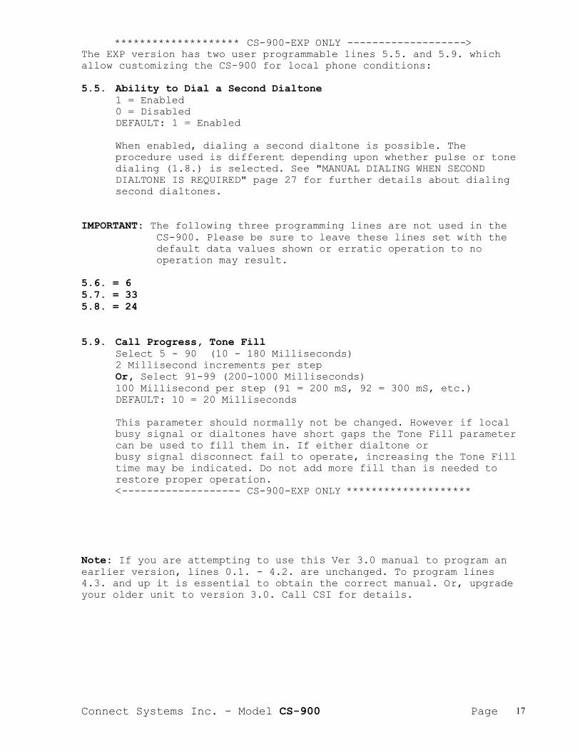
******************** CS-900-EXP ONLY ------------------->The EXP version has two user programmable lines 5.5. and 5.9. whichallow customizing the CS-900 for local phone conditions:
5.5. Ability to Dial a Second Dialtone1 = Enabled0 = DisabledDEFAULT: 1 = Enabled
When enabled, dialing a second dialtone is possible. Theprocedure used is different depending upon whether pulse or tonedialing (1.8.) is selected. See "MANUAL DIALING WHEN SECONDDIALTONE IS REQUIRED" page 27 for further details about dialingsecond dialtones.
IMPORTANT: The following three programming lines are not used in theCS-900. Please be sure to leave these lines set with thedefault data values shown or erratic operation to nooperation may result.
5.6. = 65.7. = 335.8. = 24
5.9. Call Progress, Tone FillSelect 5 - 90 (10 - 180 Milliseconds)2 Millisecond increments per stepOr, Select 91-99 (200-1000 Milliseconds)100 Millisecond per step (91 = 200 mS, 92 = 300 mS, etc.)DEFAULT: 10 = 20 Milliseconds
This parameter should normally not be changed. However if localbusy signal or dialtones have short gaps the Tone Fill parametercan be used to fill them in. If either dialtone orbusy signal disconnect fail to operate, increasing the Tone Filltime may be indicated. Do not add more fill than is needed torestore proper operation.<------------------- CS-900-EXP ONLY ********************
Note: If you are attempting to use this Ver 3.0 manual to program anearlier version, lines 0.1. - 4.2. are unchanged. To program lines4.3. and up it is essential to obtain the correct manual. Or, upgradeyour older unit to version 3.0. Call CSI for details.

Connect Systems Inc. - Model CS-900 Page 18
PROGRAMMING THE CW ID(Programming Area No. 2)
To enter the CW ID programming mode, press and hold button No. 2 onthe internal keypad and then simultaneously turn on the power switch.At this point, the display will read 0.2. When you release the No. 2button, you will see A.A.
A.A. (GOTO Any Address)Press 'P' to start at character position 0.1., or enter thecharacter position number you wish to go to and then press 'P'.
Viewing or Changing Character CodesA quick tap on 'C' will reveal (for a moment) the currentlyselected character code for the displayed characterposition. If the character code is acceptable, press 'P' toadvance to the next character position, or, enter a new charactercode and press 'P' to advance to the next characterposition.
Character Code Range CheckingIf a number greater than 38 is entered, pressing 'P' willnot cause an advance to the next character position. Thisprevents you from accidentally entering an unusable choice.
Returning to A.A.If desired, you can return to a previously programmedcharacter position by holding down 'C' for several seconds.This will return you to A.A. Now enter the characterposition (line number) you wish to return to and press 'P'.
PROGRAMMINGThe CW ID message sent from the CS-900 may consist of up to 15characters. To program the message, enter the desired character codes(from Table 1) starting at character position 0.1. through the lengthof the string. If the message is less than 15 characters, it must beterminated with code 38 (Message End). For example, to program the CWID message 'CSI':
0) Enter CW ID Programming Mode as explained above(Hold down key No. 2 and switch on the power)
1) From the A.A. line hit 'P'2) From 0.1. enter: ' 2 P' for the character "C"3) From 0.2. enter: '18 P' for the character "S"4) From 0.3. enter: ' 8 P' for the character "I"5) From 0.4. enter: '38 P' to end the message.6) Turn off the power, and then back on, to return to operate
mode with the newly programmed CW ID message.

Connect Systems Inc. - Model CS-900 Page 19
_______________________________________________________________| || TABLE 1 CW ID CHARACTER CODES ||_______________________________________________________________|| A = 0 | G = 6 | M = 12 | S = 18 | Y = 24 | 5 = 30 | WORD || B = 1 | H = 7 | N = 13 | T = 19 | Z = 25 | 6 = 31 | SPACE= 36|| C = 2 | I = 8 | O = 14 | U = 20 | 1 = 26 | 7 = 32 | || D = 3 | J = 9 | P = 15 | V = 21 | 2 = 27 | 8 = 33 | SLANT || E = 4 | K = 10 | Q = 16 | W = 22 | 3 = 28 | 9 = 34 | BAR = 37 || F = 5 | L = 11 | R = 17 | X = 23 | 4 = 29 | 0 = 35 | || | | | | | | MESSAGE || | | | | | | STOP= 38 ||_______|________|________|________|________|________|__________|| || e.g. CW ID message desired is 'CSI' Enter 2, 18, 8, 38 ||_______________________________________________________________|
-----------------------------------------------------------------
SPEED DIAL PHONE NUMBER PROGRAMMING(Programming Area No.3)
To enter the speed dial phone number programming mode, press and holdbutton No. 3 on the internal keypad and then simultaneously turn onthe power switch. At this point, the display will read 0.3. When yourelease the No. 3 button, you will see A.A. There are 90 speed diallocations numbered from 0.1. to 9.0. Each location may hold from 1 to16 digits.
A.A. (GOTO Any Address)Press 'P' to start at speed dial location 0.1., or enterthe speed dial location you wish to go to and then press 'P'.
Viewing or Changing Phone NumbersA quick tap on 'C' will reveal the phone number stored at thedisplayed line number. The phone number is displayed digit by digituntil all digits in the number have been shown. If the phone numberis acceptable, press 'P' to advance to the next line number or,enter a new phone number and press 'P' to advance to the next linenumber. The phone number stored at any line number can be erased byentering three zeros. (000P).
Note: If there is no phone number stored at the present linenumber, pressing 'C' will flash the current line number number onceinstead of showing a phone number.
Connect Systems Inc. - Model CS-900 Page 20
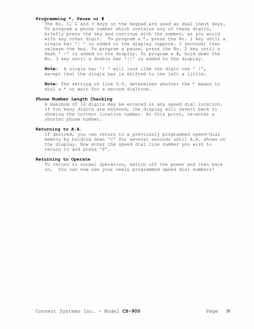
Programming *, Pause or #The No. 1, 2 and 3 keys on the keypad are used as dual input keys.To program a phone number which contains any of these digits,briefly press the key and continue with the number, as you wouldwith any other digit. To program a *, press the No. 1 key until asingle bar '| ' is added to the display (approx. 3 seconds) thenrelease the key. To program a pause, press the No. 2 key until adash ' -' is added to the display. To program a #, hold down theNo. 3 key until a double bar '||' is added to the display.
Note: A single bar '| ' will look like the digit one ' |',except that the single bar is shifted to the left a little.
Note: The setting of line 5.5. determines whether the * means todial a * or wait for a second dialtone.
Phone Number Length CheckingA maximum of 16 digits may be entered in any speed dial location.If too many digits are entered, the display will revert back toshowing the current location number. At this point, re-enter ashorter phone number.
Returning to A.A.If desired, you can return to a previously programmed speed-dialmemory by holding down 'C' for several seconds until A.A. shows onthe display. Now enter the speed dial line number you wish toreturn to and press 'P'.
Returning to OperateTo return to normal operation, switch off the power and then backon. You can now use your newly programmed speed dial numbers!

Connect Systems Inc. - Model CS-900 Page 21
TOLL OVERRIDE PROGRAMMING(Programming Area No. 4)
To enter the TOLL OVERRIDE programming area, press and hold button No.4 on the internal keypad and then simultaneously turn on the powerswitch. At this point, the display will read 0.4. When you release theNo. 4 button, you will see A.A.
A.A. (GOTO Any Address)Press 'P' to begin entering TOLL OVERRIDE selections into memoryline 0.1., or enter the TOLL OVERRIDE line number you wish to go toand then press 'P'.
Viewing or changing TOLL OVERRIDE codesA quick tap on 'C' will reveal the user programmed TOLL OVERRIDEcode at the current line number. The TOLL OVERRIDE code isdisplayed digit by digit until all digits in the code have beenshown. If the TOLL OVERRIDE code is acceptable, press 'P' toadvance to the next programming line and enter the next overridecode etc. Any memory line number can be erased by entering threezeros followed by P (000P).
Note: If there is no TOLL OVERRIDE code programmed at the currentline number, pressing 'C' will flash the current line number onceinstead of showing a programmed TOLL OVERRIDE code.
Programming a Wildcard (*)The No. 1, key on the keypad is used as a dual input key. A briefpress enters a 1. If the 1 button is held down for three or moreseconds it becomes a * entry. The display will show '| ' whichindicates a * has been entered.
Note: A single bar '| ' will look like the digit one ' 1',except that the single bar is shifted to the left a little.
Returning to A.A.If desired, you can return to a previously programmed TOLLOVERRIDE location by holding down 'C' for several seconds untilA.A. shows on the display. Now enter the TOLL OVERRIDE line numberyou wish to return to and press 'P'.
Returning to OperateTo return to normal operation, switch off the power and then backon. Your newly programmed TOLL OVERRIDE codes are now active.
Connect Systems Inc. - Model CS-900 Page 22
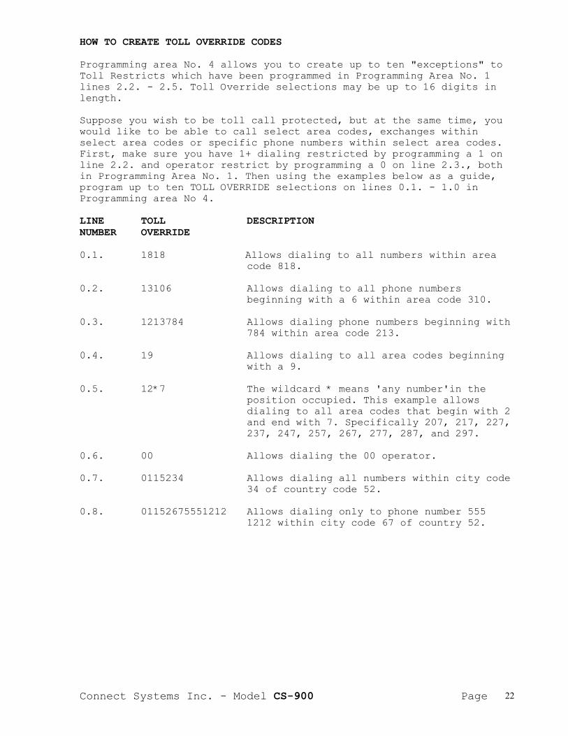
HOW TO CREATE TOLL OVERRIDE CODES
Programming area No. 4 allows you to create up to ten "exceptions" toToll Restricts which have been programmed in Programming Area No. 1lines 2.2. - 2.5. Toll Override selections may be up to 16 digits inlength.
Suppose you wish to be toll call protected, but at the same time, youwould like to be able to call select area codes, exchanges withinselect area codes or specific phone numbers within select area codes.First, make sure you have 1+ dialing restricted by programming a 1 online 2.2. and operator restrict by programming a 0 on line 2.3., bothin Programming Area No. 1. Then using the examples below as a guide,program up to ten TOLL OVERRIDE selections on lines 0.1. - 1.0 inProgramming area No 4.
LINE TOLL DESCRIPTIONNUMBER OVERRIDE
0.1. 1818 Allows dialing to all numbers within areacode 818.
0.2. 13106 Allows dialing to all phone numbersbeginning with a 6 within area code 310.
0.3. 1213784 Allows dialing phone numbers beginning with784 within area code 213.
0.4. 19 Allows dialing to all area codes beginningwith a 9.
0.5. 12*7 The wildcard * means 'any number'in theposition occupied. This example allowsdialing to all area codes that begin with 2and end with 7. Specifically 207, 217, 227,237, 247, 257, 267, 277, 287, and 297.
0.6. 00 Allows dialing the 00 operator.
0.7. 0115234 Allows dialing all numbers within city code34 of country code 52.
0.8. 01152675551212 Allows dialing only to phone number 5551212 within city code 67 of country 52.
Connect Systems Inc. - Model CS-900 Page 23
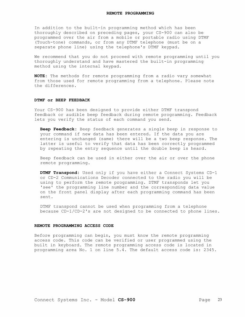
REMOTE PROGRAMMING
In addition to the built-in programming method which has beenthoroughly described on preceding pages, your CS-900 can also beprogrammed over the air from a mobile or portable radio using DTMF(Touch-tone) commands, or from any DTMF telephone (must be on aseparate phone line) using the telephone's DTMF keypad.
We recommend that you do not proceed with remote programming until youthoroughly understand and have mastered the built-in programmingmethod using the internal keypad.
NOTE: The methods for remote programming from a radio vary somewhatfrom those used for remote programming from a telephone. Please notethe differences.
DTMF or BEEP FEEDBACK
Your CS-900 has been designed to provide either DTMF transpondfeedback or audible beep feedback during remote programming. Feedbacklets you verify the status of each command you send.
Beep Feedback: Beep feedback generates a single beep in response toyour command if new data has been entered. If the data you areentering is unchanged (same) there will be a two beep response. Thelatter is useful to verify that data has been correctly programmedby repeating the entry sequence until the double beep is heard.
Beep feedback can be used in either over the air or over the phoneremote programming.
DTMF Transpond: Used only if you have either a Connect Systems CD-1or CD-2 Communications Decoder connected to the radio you will beusing to perform the remote programming. DTMF transponds let you'see' the programming line number and the corresponding data valueon the front panel display after each programming command has beensent.
DTMF transpond cannot be used when programming from a telephonebecause CD-1/CD-2's are not designed to be connected to phone lines.
REMOTE PROGRAMMING ACCESS CODE
Before programming can begin, you must know the remote programmingaccess code. This code can be verified or user programmed using thebuilt in keyboard. The remote programming access code is located inprogramming area No. 1 on line 5.4. The default access code is: 2345.

Connect Systems Inc. - Model CS-900 Page 24
SELECTING THE DESIRED PROGRAMMING AREA AND FEEDBACK
The type of feedback (beep or DTMF transpond) desired as well as theprogramming area (1-4) you wish to program are selected by appendingthe access code with a digit from the Table below.
In over the air programming, you have a choice of either beep responseor DTMF transpond. Therefore select 1-8.
When programming from a telephone, you are limited to beep responsefeedback. Therefore select 1-4 only.
1 = Programming area No. 1 with beep response.2 = Programming area No. 2 with beep response.3 = Programming area No. 3 with beep response.4 = Programming area No. 4 with beep response.5 = Programming area No. 1 with DTMF transpond.6 = Programming area No. 2 with DTMF transpond.7 = Programming area No. 3 with DTMF transpond.8 = Programming area No. 4 with DTMF transpond.
SIGNIFICANCE OF THE * AND # KEYS
The * and # keys on a DTMF pad are in the same physical position asthe C and P keys on the built-in keyboard. When in remote programming,the * and # serve similar functions. It's important to understand howthese keys operate in remote programming mode:
1. The # key acts similar to the P key in most respects:a) When new data has been typed at the current programming line, the # serves as an enter key. The programming line number does
NOT advance if data has been entered.b) If data has not been entered since last using the # as an enter
key, the # then advances the programming line to the nextsequential line number (not the next logical line number aswhen programming with the built-in keyboard).
2. The * key acts similar to the C key in most respects:a) Hold down at any time for more than one second to return to
A.A.b) Enter 0* at any time to return to A.A.c) Move to any desired line number by entering the line number
followed by *. For example 14* would position you at line 1.4.d) A quick tap (less than one second) of the * will cause the CS-
900 to transpond the data at the current line number if usingDTMF transpond mode. A quick tap of the * has no effect ifusing beep feedback mode.
3. When needed, A long press is one second rather than three secondswhen entering a *, pause or # in the speed dialer area (ProgrammingArea No. 3).
Connect Systems Inc. - Model CS-900 Page 25
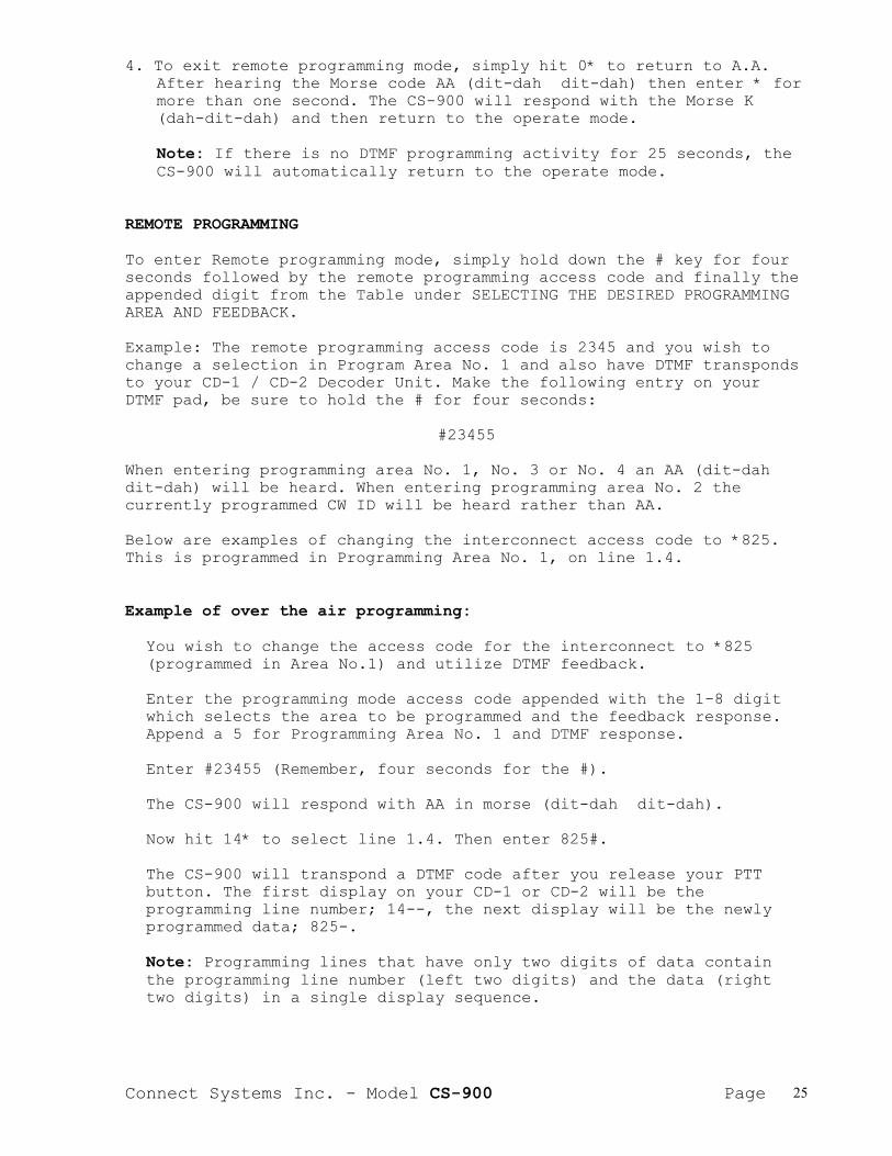
4. To exit remote programming mode, simply hit 0* to return to A.A.After hearing the Morse code AA (dit-dah dit-dah) then enter * formore than one second. The CS-900 will respond with the Morse K(dah-dit-dah) and then return to the operate mode.
Note: If there is no DTMF programming activity for 25 seconds, theCS-900 will automatically return to the operate mode.
REMOTE PROGRAMMING
To enter Remote programming mode, simply hold down the # key for fourseconds followed by the remote programming access code and finally theappended digit from the Table under SELECTING THE DESIRED PROGRAMMINGAREA AND FEEDBACK.
Example: The remote programming access code is 2345 and you wish tochange a selection in Program Area No. 1 and also have DTMF transpondsto your CD-1 / CD-2 Decoder Unit. Make the following entry on yourDTMF pad, be sure to hold the # for four seconds:
#23455
When entering programming area No. 1, No. 3 or No. 4 an AA (dit-dahdit-dah) will be heard. When entering programming area No. 2 thecurrently programmed CW ID will be heard rather than AA.
Below are examples of changing the interconnect access code to *825.This is programmed in Programming Area No. 1, on line 1.4.
Example of over the air programming:
You wish to change the access code for the interconnect to *825(programmed in Area No.1) and utilize DTMF feedback.
Enter the programming mode access code appended with the 1-8 digitwhich selects the area to be programmed and the feedback response.Append a 5 for Programming Area No. 1 and DTMF response.
Enter #23455 (Remember, four seconds for the #).
The CS-900 will respond with AA in morse (dit-dah dit-dah).
Now hit 14* to select line 1.4. Then enter 825#.
The CS-900 will transpond a DTMF code after you release your PTTbutton. The first display on your CD-1 or CD-2 will be theprogramming line number; 14--, the next display will be the newlyprogrammed data; 825-.
Note: Programming lines that have only two digits of data containthe programming line number (left two digits) and the data (righttwo digits) in a single display sequence.
Connect Systems Inc. - Model CS-900 Page 26
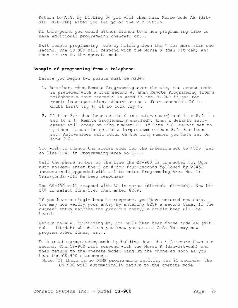
Return to A.A. by hitting 0* you will then hear Morse code AA (dit-dah dit-dah) after you let go of the PTT button.
At this point you could either branch to a new programming line tomake additional programming changes, or...
Exit remote programming mode by holding down the * for more than onesecond. The CS-900 will respond with the Morse K (dah-dit-dah) andthen return to the operate mode.
Example of programming from a telephone:
Before you begin two points must be made:
1. Remember, when Remote Programming over the air, the access codeis preceded with a four second #. When Remote Programming from atelephone a four second * is used if the CS-900 is set forremote base operation, otherwise use a four second #. If indoubt first try #, if no luck try *.
2. If line 3.8. has been set to 0 (no auto-answer) and line 5.4. isset to a 1 (Remote Programming enabled), then a default auto-answer will occur on ring number 11. If line 3.8. is not set to0, then it must be set to a larger number than 3.4. has beenset. Auto-answer will occur on the ring number you have set online 3.8.
You wish to change the access code for the interconnect to *825 (seton line 1.4. in Programming Area No.1)...
Call the phone number of the line the CS-900 is connected to. Uponauto-answer, enter the * or # for four seconds followed by 23451(access code appended with a 1 to enter Programming Area No. 1).Transponds will be beep responses.
The CS-900 will respond with AA in morse (dit-dah dit-dah). Now hit14* to select line 1.4. Then enter 825#.
If you hear a single beep in response, you have entered new data.You may now verify your entry by entering 825# a second time. If thecurrent entry matches the previous entry, a double beep will beheard.
Return to A.A. by hitting 0*, you will then hear Morse code AA (dit-dah dit-dah) which lets you know you are at A.A. You may nowprogram other lines, or...
Exit remote programming mode by holding down the * for more than onesecond. The CS-900 will respond with the Morse K (dah-dit-dah) andthen return to the operate mode. Hang up the phone as soon as youhear the CS-900 disconnect.Note: If there is no DTMF programming activity for 25 seconds, the
CS-900 will automatically return to the operate mode.
Connect Systems Inc. - Model CS-900 Page 27
OPERATION
Important: The CS-900 displays all DTMF digits on the internaldisplay as they are decoded. The DTMF digits * and # are shown as a'| ' and '||'. If the CS-900 is set for pulse dialout (1.8. set to0) the display shows the phone number currently being outpulsedrather than the incoming DTMF.
PLACING OUTGOING CALLS
DIALING A CALL MANUALLY: From the mobile press *, then enter theaccess code (if any) that was selected on line 1.4. or, enter thesecret toll override access code that was set on line 1.5. If theaccess delay on line 1.9. is properly set, you will hear dialtone orCW ID start without clipping or delay. The dialtone will last about 3seconds and then drop off. Begin dialing your intended phone numberwithin ten seconds after dialtone drops or the CS-900 will assume youhave changed your mind and will sign off. After dialing, the nextthing heard will either be ringing or a busy signal. If 2.9. isenabled, the CS-900 will automatically disconnect if the number thatwas called is busy.
******************** CS-900-EXP ONLY ------------------->MANUAL DIALING WHEN SECOND DIALTONE IS REQUIRED: Programming line 5.5.must be set to 1 to allow second dialtone dialing. The procedure is abit different for Tone and Pulse dialing.
Pulse dial: If 1.8. is set to 0 (pulse dial) a second dialtone isdialed by preceding the number intended for the second dialtonewith *. This causes the CS-900 to wait until the second dialtoneappears and to then automatically continue dialing. Example: Youneed to call 555 3456 after dialing an 8 for long distance. Simplydial 8 * 555 3456 as a complete sequence immediately following thedrop of first dialtone. The CS-900 will then pulse dial the 8 andwait until the second dialtone is detected and then continue the555 3456 portion. A beep is heard about every six seconds whilewaiting for the second dialtone which lets you know the CS-900 isstill actively processing your call.
Tone dial: If 1.8. is set to 1 (tone dialing) Dial the firstportion plus a * after the first dialtone drops. Wait until thesecond dialtone is heard and drops and then dial the remainingportion. Example; You need to call 555 3456 after dialing an 8 forlong distance. Simply dial 8* after the first dialtone drops and555 3456 after the second dialtone drops. A beep is heard aboutevery six seconds while waiting for the second dialtone.
Note: Third or more dialtones can also be accommodated by simplyadding a * after each group requiring a wait for another dialtone.Do not append a * on the final group or you will be forever waitingfor another dialtone.
<------------------- CS-900-EXP ONLY ********************

Connect Systems Inc. - Model CS-900 Page 28
PROGRAMMING THE SPEED DIALER FROM THE MOBILE: Writing a phone numberinto the speed dialer memory from the mobile is accomplished with aslight variation on ordinary manual dialing. Before you enter youraccess code, send 9 followed by the desired memory location number.e.g. You wish to place a call to 277-1463 and simultaneously add thenumber to speed dial memory location 6. From the mobile, enter 9 6then the access code. When the dialtone is heard, dial 277-1463 justas you would in ordinary manual dialing. You will never have tomanually dial 277-1463 again!
Note: The 9 as used above means WRITE the phone number to be dialedinto the memory location specified immediately following the 9.
Note: Phone numbers containing a * for second dialtone wait cannotbe remotely programmed if using tone dialing. These numbers can onlybe programmed using the internal keyboard.
You can program a *, pause or # as part of a speed dial sequence ifdesired. The digits 1,2 and 3 are interpreted as *, pause and # ifheld down for 4-5 seconds during the dialing process.
For example: you wish to program; 8 pause 472-8197 into memorylocation No. 3. Enter in order; 9 3 then your access code. Then afterdialtone enter 8, long 2, 472-8197. The number you have dialed is nowproperly loaded into memory location No. 3. However the long 2 willcause a misdial of the immediate call. When a *, pause or # has beenused, do not let the call go through. Send the disconnect commandafter the number has been dialed and call back using the speed dialer.The call will now dial properly.
1-800 DIALING: The CS-900 will allow dialing to toll free 1-800numbers even if 1 is set as a restricted first digit. However, if youare going to restrict 1, you must restrict it on line 2.2.
CALL WAITING: If line in use detection has been enabled, the CS-900checks to see if the line is in use when a mobile attempts access. Ifthe line is free the mobile will hear dialtone and can proceed withhis call. If the line is in use, the CS-900 will send a special busysignal to the mobile and revert to the stand-by condition. At the sametime, Call Waiting beeps let those using the line know that a mobileunit would like to use the line. When the telephone users hang-up,beeps let the mobile know that the line is now free to use.
The mobile can cut-in on the call if desired by using the secret tolloverride code (1.5.) after hearing the line in use busy signal. Athree way conversation can now take place.

Connect Systems Inc. - Model CS-900 Page 29
PLACING A CALL WITH THE SPEED DIALER: Once a phone number has beenstored, calling back is a snap! Simply precede the access code withthe appropriate memory location number. Soon, your intended numberwill be ringing. Example: Your access code has been set as * only. Youwish to call a friend whose phone number has been previously stored inlocation 24. Simply enter 24 * on your mobile keypad. Another example:Your access code is *391, and you wish to speed dial the number inmemory location No. 7. Enter 7*391, that's all there is to it!
Note: An error message consisting of eight beeps will be heardif you attempt to speed dial an unused memory location.
LAST NUMBER REDIAL: The last phone number called is alwaysautomatically stored at speed dial memory location NO. 0. To redialthe last number called, simply precede the access code (1.4.) with 0.Similar to using the speed dialer. e.g. 0*, 0*391 etc.
HOOK FLASH: The CS-900 has built-in hook flash logic to operatecertain phone company provided features. To flash, simply press *three times (***). WARNING: The 570 ms. (on-hook) flash can cause adisconnect on some phone lines.
ACTIVITY TIMER: Once your number has been dialed, the activity timerstarts operating. The activity timer behaves per selections made onprogram lines, 0.7. and 2.6. A warning beep is heard every two secondsduring the second half of the programmed timeout interval. The beepswarn of impending timeout.
The activity timer measures phone line audio activity. Phone lineactivity causing a single transmission exceeding the time set in 2.6.will cause one of two responses as selected on line 0.7.
1. If a "1" (stand-by) was programmed on line 0.7. the CS-900 willsimply go off the air, but will not disconnect your call.Pressing * from the mobile will restore normal operation.(Assuming you wish to continue listening to the audio that causedthe timeout).
2. If a "0" (disconnect) was programmed on line 0.7. the CS-900 willdisconnect, and the call in progress will be lost.
TIMEOUT TIMER: Calls will automatically disconnect at the end of thetime you selected on line 2.7. Two quick beeps heard in successionevery two seconds during the final twenty seconds warn that time outis imminent. The timeout timer can be reset by the mobile by pressing*.
Note: The CS-900 can not hear your reset command if it istransmitting to you. Wait until the Cs-900 has returned toreceive before you send * to reset the timeout timer.

Connect Systems Inc. - Model CS-900 Page 30
DISCONNECTING WHEN THROUGH: If a "0" was entered on line 1.6. simplypress # to disconnect. If a "1" was entered, press # plus the connectdigits that were selected on line 1.4.
FIVE PRESS AUTO DIAL: If a "1" was entered on line 1.7., the phonenumber residing in speed dial memory location No. 1 can beautomatically dialed by pressing the mobile Mic button five times insuccession. When the call is finished, five more presses will causedisconnect. WARNING: If you press too fast or too slow the CS-900 willnot respond. The correct rate is about one press per second. Thistiming is required to keep rapid mobile fading and normal on channelMic button pressing from falsing the patch on and/or off.
EXTERNAL CONNECTION NOTE: This feature can not operate without aninternal COS connection to the receiver.
INCOMING CALLS
RINGOUT: Lines 3.3. through 3.7. allow you to customize ringout foryour application. Ringout is how the CS-900 alerts you to the presenceof an incoming call.
When a call comes in, the CS-900 first checks to see if the channel isin use (3.3.). The incoming rings are counted (3.4.) before a mobilealert is sent. The alert can consist of a Ring Tone that sounds like atelephone ringing or a CW ID (3.5.). You may also preface the ringoutwith a sequential DTMF sequence (3.6.). The user programmable DTMFsequence can be used to operate attention getters such as a hornhonker. The type of alert selected can be set to occur only once or onalternate rings (3.7.) of the incoming call.
To answer your call from the mobile, simply enter your access code(1.4.). When you complete your call, send the disconnect code (1.6).
AUTO ANSWER: The CS-900 must be set to automatically answer (3.8.)incoming calls if you wish to use the Remote Base or DTMF SelectiveCall modes.
Note: If ringout is set to occur earlier in the ring cycle (3.4.)than auto answer (3.8.), it is possible to receive ordinary incomingcalls plus use the modes which require an auto answer.
TELEPHONE REMOTE BASE: You can dispatch and have full use of yoursystem from any telephone by entering a 1 or 2 on (3.9.)...
Enter 0 if you are going to use mobile selective calling.
Enter 1 if you would like to access your radio system (Remote Base)from any phone without the need to enter an access code.

Connect Systems Inc. - Model CS-900 Page 31
Enter 2 if you prefer that an access code is required to enter remotebase mode. Dial as described below after the beep:
From DTMF Telephones: Use mobile access code programmed on 1.4.
From Dial Pulse Phones: Will only operate if mobile access code is *(1.4. = 0) and DTMF signalling has been selected. Simply dial 0 fromthe dial pulse phone.
When your remote base dispatch is finished, send the disconnect code(1.6.) before you hang-up. If you forget, built-in safe-guards such ascall progress tone detection will automatically disconnect the CS-900on most phone systems.
Note: A dial pulse phone can not turn off the CS-900 when through.The timeout or activity timer must perform the disconnect. (Or, themobile can disconnect by sending #).
SELECTIVE CALLING: Any mobile or portable radio equipped with a DTMFdecoder can be selectively called from either a DTMF or dial pulsetelephone...
From DTMF Telephones: After the auto-answer beep, enter the desiredDTMF selective call sequence followed by *.
For example: XXXXX* (x's any length, any sequence).
The CS-900 will hold the auto answered call for thirty secondsgiving the mobile time to respond. To answer a call and activate twoway voice capability, the mobile must send the connect code (1.4.).When the call is completed, the mobile should send the disconnectcode (1.6.).
From Dial Pulse Phones: (Dial click detect or EXP option required).After the auto-answer beep, dial 0 followed by the desired selectivecall sequence.
For example: 0XXXXX (x's any length, any sequence).
The CS-900 will hold the auto answered call for thirty secondsgiving the mobile time to respond. To answer a call and activate twoway voice capability, the mobile must send the connect code (1.4.).When the call is completed, the mobile should send the disconnectcode (1.6.).
REMOTE BASE WITH SELECTIVE CALLING: (From DTMF phones only) RemoteBase with selective calling can be accessed by entering the connectcode (1.4.) after the auto-answer beep. You can then send anyselective call code by entering the appropriate digits followed by *.(Remote base mode 3.9. must be set to 0 if selective calling is to beused).
Example: You've selected *7 as your access code (1.4.) and you wish tosend the selective call code 639. After the auto answer beep enter *7639*.

Connect Systems Inc. - Model CS-900 Page 32
OPERATION THROUGH REPEATERS OR TRUNKED SYSTEMS
Operating the CS-900 through a repeater appears to the user asstraight simplex operation. It makes no difference if the repeater isDPL/CTCSS or carrier activated, or if the repeater has hang time.Actually, three or four seconds of hang time will improve operationbecause there will be fewer noises to distract the conversation.
The built-in .5 second electronic voice delay eliminates anypossibility of word clipping or loss.
Note: See comments on setting the RX VOX control on page 6.
CALL PROGRESS TONE DETECTION
CALL PROGRESS TONE DETECTION: The CS-900 incorporates verysophisticated software algorithms that automatically sense thepresence of dialtone and/or busy signals. The method used willfunction with any tone frequencies. There is nothing to adjust ormaintain, it's completely automatic!
Note: On lines 2.9. and 3.0. you can selectively enable or disablebusy signal disconnect and dialtone disconnect for specialapplications.
******************** CS-900-EXP ONLY ------------------->Programming line 5.9. allows customizing call progress tone detectionto operate on most any telephone system.
<------------------- CS-900-EXP ONLY ********************
Connect Systems Inc. - Model CS-900 Page 33
TYPICAL APPLICATIONS FOR THE AUXILIARY RELAY(Option 901)
Remote_CTCSS_Enable/Disable: When using the CS-900 as a Remote Base,it is desirable to monitor the channel for activity prior todispatching. The auxiliary relay can be used to allow the remoteswitching of the radio's hook switch. Pressing 0 turns the relay on.Pressing * turns the relay back off. Thus the radio can be set tocarrier receive and back to DPL/CTCSS operation remotely.
Enter 1 (Monitor) on line 3.1. Connect the normally closed relaycontacts (W and NC) in series with the radio's hook switch.
Disabling_tone_squelch: Many of the new microprocessor controlledradios will not transmit when the microphone is on hook. The auxiliaryrelay can be used to fool the radio into thinking the MIC is off-hook.
Enter 0 (Connect) on line 3.1. This will energize the relay wheneverthe CS-900 is in use. Connect the normally closed contacts (W and NC)in series with the radio's hook switch.
Relay_Switched_PTT: If the radio's unkeyed PTT voltage exceeds 16 VDCor if inverted keying is required (closure to 12V) the auxiliary relaymust be used to key the transmitter.
Enter 2 (KEY) on line 3.1. Connect the radio's PTT line to one of theAux. Relay contacts on the rear barrier strip. Connect the other Aux.Relay contact to 12 VDC for inverted keying or to GND for sink toground keying. Make sure JP-7 is strapped from the center to the NOposition. The PTT connection on the rear barrier strip should not beconnected.
Remote_Relay_Function: In some installations it may be desirable toremotely control (switch) something from the mobile. e.g. changechannels, change CTCSS tones, change antennas etc.
Enter 3 (REMOTE FUNCTION) on line 3.1. Then select a three digitcontrol code on line 3.2. If the code selected was 789, you would turnon the Remote Relay by sending #789. To turn off the relay send ##789.
CONNECTING THE RELAYConnect the device requiring remote control to the two terminalslabeled 'AUX. RELAY' on the rear panel barrier block. The CS-900 issupplied with the relay strapped for normally open operation. ifnormally closed operation is desired, see JP-7 on page 6 for details.

Connect Systems Inc. - Model CS-900 Page 34
GLOSSARY
COS Carrier Operated Squelch
DCS Digital Coded Squelch
CTCSS Continuous Tone Coded Squelch System
JP Jumper (Schematic designator)
CCW Counter Clockwise
POT Potentiometer
PCB Printed Circuit Board
CW ID Continuous Wave Identification (International Morse Code)
FCC Federal Communications Commission (USA)
DOC Department of Communications (Canada)
CO lines Central Office Lines (telephone lines from phone company)
ANI Automatic Number Identification
DTMF Dual Tone Multi-Frequency (touch tone dialing format
PTT Push to Talk (transmitter keying using microphone switch)

Connect Systems Inc. - Model CS-900 Page 35
LIMITED WARRANTYConnect Systems Inc. (CSI) hereby warrants our products to be free fromdefective workmanship for a period of one year and defective parts for aperiod of five years from date of sale to the initial end user. This warrantyapplies only to the original consumer/end user purchaser of each CSI product.During the first year of warranty, CSI will repair any of its products at nocharge providing the defective unit is shipped prepaid and service isperformed by CSI. During the years 2 -5, there shall be no charge forreplacement parts providing that the defective unit is shipped prepaid andservice is performed by CSI. Conventional prevailing labor and shippingcharges will apply following the end of the first year. CSI, at its solediscretion, will replace defective parts on an exchange basis for the firstfive years of ownership by the original purchaser. All shipping cost are theresponsibility of the customer.
What is not covered by this limited warranty:
This warranty shall not apply, if, in our judgment the defects are caused bymisuse, lightning strikes, customer modification, water damage, negligent use,improper installation, overloads caused by external voltage fluctuations, useof unregulated power supply, damage caused by transit or handling or anabusive treatment not in accordance with ordinary product use or the productserial number has bee removed, altered, or defaced. Specific Exclusion: Thiswarranty specifically excludes lightning protection devices (MOVs and phoneline fuses) and transistors in the PTT (Push to Talk) circuitry. Thesecomponents can only fail from external abuse.
THIS WARRANTY IS IN LIEU OF ALL OTHER WARRANTIES, STATEMENTS ORREPRESENTATIONS, AND UNLESS STATED HEREIN, ALL SUCH WARRANTIES,STATEMENTS OR REPRESENTATIONS MADE BY ANY OTHER PERSON OR FIRM AREVOID. ALL IMPLIED WARRATIES IN CONNECTION WITH THE SALE OF THISEQUIPMENT, INCLUDING THE WARRANTY OF MERCHANTABILITY, SHALL BE OF THESAME DURATION AS THE WARRANTY PERIOD STATED ABOVE. SOME STATES DO NOTALLOW LIMITATIONS OF HOW LONG AN IMPLIED WARRANTY LAST, SO THE ABOVELIMITATION MAY NOT APPLY TO YOU. IN THE EVENT OF PRODUCT FAILURE WHICHPROVES TO BE CAUSED BY A DEFECT IN WORKMANSHIP OF MATERIALS, YOUR SOLEREMEDY SHALL BE THE REPAIR OF THE DEFECT BY CSI OR ITS APPOINTEDREPAIR STATION AS STATION AS STATED IN THIS WARRANTY, AND UNDER NOCIRCUMSTANCES SHALL CSI BE LIABLE FOR ANY LOSS OR DAMAGE, DIRECT,INCIDENTAL, OR CONSEQUENTIAL, ARISING OUT OF THE USE, OR INABILTY TOUSE, THIS PRODUCT. SOME STATES DO NOT ALLOW THE EXCLUSION ORLIMITATION OF INCIDENTAL OR CONSEQUENTAL DAMAGES, SO THE ABOVELIMITATION OR EXCLUSION MAY NOT APLLY TO YOU.
If your new CSI product shall ever fail, contact Connect SystemsInc. Customer Service Dept. for repair and warranty information at(805) 642-7184
Note: Connect Systems Inc. reserves the right to render a modestservice charge when returned units are found to be free of parts orworkmanship defect(s) (i.e. operating to factory specification) withinthe first year of warranty. Such units will be returned freightcollect to the sender, including the appropriate service charge.
Connect Systems Inc. - Model CS-900 Page 36
Connect Systems Inc. - Model CS-900 Page 37

Connect Systems Inc. - Model CS-900 Page 38
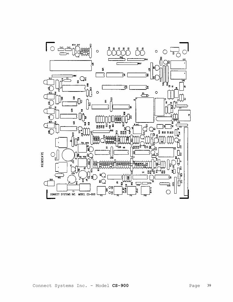
Connect Systems Inc. - Model CS-900 Page 39

Connect Systems Inc. - Model CS-900 Page 40
APPENDIX A
FCC NOTICE TO USERS-------------------
1. This equipment complies with part 68 of the FCC rules. On thebottom of this equipment is a label that contains, among otherinformation, the FCC registration number and ringer equivalencenumber (REN) for this equipment. If requested, this informationmust be provided to the telephone company.
2. The REN is used to determine the quantity of devices which may beconnected to the telephone line. Excessive REN's on the telephoneline may result in the device not ringing in response to anincoming call. In most, but not all areas, the sum of the REN'sshould not exceed five (5.0). To be certain of the number ofdevices that may be attached to the line, as determined by thetotal REN's contact the telephone company to determine the maximumREN for the area.
3. If this product causes harm to the telephone network, the telephonecompany will notify you in advance that temporary discontinuance ofservice may be required. But if advance notice isn't practical, thetelephone company will notify the customer as soon as possible.Also, you will be advised of your right to file a complaint withthe FCC if you believe necessary.
4. The telephone company may make changes in it's facilities,equipment, operations, or procedures that could affect theoperation of the equipment. If this should happen, the telephonecompany will provide advance notice in order for you to make thenecessary modifications in order to maintain uninterrupted service.
5. If trouble is experienced with this product, please contact ConnectSystems Incorporated at (805) 642-7184 for repair and warrantyinformation. If the trouble is causing harm to the telephonenetwork, the telephone company may request you remove the equipmentfrom the network until the problem is resolved.
6. There are no repairs that can be accomplished by the user. In theevent of operation problems, disconnect your unit by removing themodular plug from the telephone company modular jack. If yourregular telephone still works correctly, your unit has a problemand should be returned for repairs (in or out of warranty). If upondisconnection of your unit there is still a problem on your line,notify the telephone company that they have a problem and requestprompt repair service. The unit may be returned to Connect SystemsIncorporated, 2259 Portola Rd. Ventura, CA 93003.
7. This interconnect product cannot be used on a public coin serviceprovided by the telephone company. Connect to Party Line Service issubject to state tariffs. Contact the state public utilitycommission, public service commission or corporation commission forinformation.

Connect Systems Inc. - Model CS-900 Page 41
8. This device complies with part 15 of the FCC rules. Operation issubject to the following two conditions: (1) This device may notcause harmful interference, and (2) This device must accept anyinterference received, including interference which may causeundesirable operation.
9. This equipment generates and uses radio frequency energy and if notinstalled and used properly, i.e. in strict accordance with theservice manual, may cause interference to radio or televisionreception. It has been tested and found to comply with the limitsfor a Class B computing device pursuant to Subpart J of Part 15 ofFCC rules, which are designed to provide reasonable protectionagainst such interference when operated in a residentialinstallation.
10 If this equipment does cause interference to radio or televisionreception, which can be determined by turning the equipment off andon, the user is encouraged to try to correct the interference byone or more of the following measures:
a. Reorient the receiving antenna.
b. Relocate the equipment with respect to the receiver.
c. Move the equipment away from the receiver.
d. Plug the equipment into a different outlet so that equipment andreceiver are on different branch circuits.
e. Ensure that card mounting screws, attachment connectorscrews, and ground wires are tightly secured.
f. If cables not offered by this company are used with thisequipment, it is suggested that you use shielded, groundedcables with in line filters, if necessary.
g. If necessary consult your dealer service representative foradditional suggestions.
11 The manufacturer is not responsible for any radio or TVinterference caused by unauthorized modifications to thisequipment. It is the responsibility of the user to correct suchinterference.