model - conse · consolidated sewing machine corp. model 345-3 345-3p parts book . ... be sure to...
TRANSCRIPT

®
CONSOLIDATED SEWING MACHINE CORP.
MODEL 345-3
345-3P
PARTS BOOK

CONTENTS
(fE:ATURES:) ..................................................................................................................... 1
(S'eeCIFICATIONS) ...................................................................................................... 2
(t~t3,[E QF/stANDAaO,GAVGe) ........................................................................ 2
(I~S~r;ALLl~~) .................................................................................................................. 3
II! Installing the Machine Head ......................................................................................................... 3 121 Installing the Treadle and Chain ................................................................................................... ~
~ Installing the Motor Pulley········· .... ·· .. · .. · .. · .. · .. ···· .. ···· .. · .. ··· ...... · .. · .. · .. · .. · .. · .. ···· .. · ... · .. · ... ···················· 4 [4] Belt Tension. adjustment ............................................................................................................... 4 I5l Installing the Pulley Cover ............................................................................................................ 4 I2l Motor and Motor Pulley ............................................................................................................... 4
IZI Spool Stand· .. · .... ·· .... ····· .. ··· .. · .. ···· .... ····· .. ····· .. · .. ··· .. ···· .. ······· .. · .. ·· .... · .. ···· .. ·· .... · ... ·· .. ·· .. · .. · .. ···· .. · .. · .. · 4
.................................................................. 4
II! Lubrication ................................................................................................................................. 4 121 Running In ................................................................................................................................. 5
.......................................................................................... 5
II! Needles and Threads· .... ·· .. ··· .... ·· .. · .. · .. · .. ·· .... · .. ········ .. · .... · .... ·· .. · .. · ................................................... 5 121 Installing the Needles ...................................... , .................... . .............................. ...... ...... ... ......... 5 ~ Upper Threading ................................................................................................ '........................ 6 [4] Lower Threading ........................................................................................................................ 6
I5l Installing the Lapper .. · .. · .. · .. ·· .. · ...... · .... ··· .... ·· .. · .. ·· .. ········ .. · .. ·· .. · .. · .. · .. · .. · ..... ·· ........ · ........ ·.··· .... ·........ 7 I2l Sewing ....................................................................................................................................... 7 IZI Thread Tension ........................................................................................................................... 7 I§] Presser Foot Pressure Adjustment ................................................................................................ 8 ~ Stitch Length Adjustment ............................................................................................................ 8 I!Ql Puller Feed Adjustment ................................................................................. 8
.............................................................................. 10
II! Needle and Looper Timing Adjustment .................... · .................................................................... ·10 121 Needle Bar Height Adjustment ...................................................................................................... 10
~ Looper Timing for Avoiding Contact with Needles .. · .............. · .. · .......... · ........ · .............. · .......... · ........ ll [4] Needle Guard Adjustment ................................................................................. · .... · .. · .. · .. · .. ···· .. ·· .. 11
I5l Feed Dog Height Adjustment .... · .. ·· .. · .... ······ .... · .... ··· .. ····· ............ · .. · .. · .. ·· .... ····· .. · ........ ········· .. · .. ·· .... ·12 I2l Puller Height Adjustment ............................................................................. ·12 IZI Installing the Spacer (For tne demm specifications) ........................................................................ · .. 13 I§] Upper Thread Take-up Thread Guide Adjustment ........................................................................... 13 ~ Thread Release Lever Adjustment ............................................................................................... ·13 I!Ql Thread Release Shaft Adjustment .. ···· ............................................................................. ·· ....... · .... ··14 [J] Upper Thread Nipper Adjustment ., ..................................................................................... · .. ·· .. ··14
IIZI Lower Thread Take-up Timing Adjustment· .... ········ .. · .... ······· .. · .. ·· .... · .. ·· .. ··· .. ···· .. · .. ··· .. ··· .. · .. ···· .. · .... ·14 fil Puller Device Timing Adjustment .... · .. · ................................... ·····.· .. · .. ····14
(TROUBLESHOOTING)····································· ...................................................... ·····15

*Model -345" Double Chain Stitch Feed-off-the-arm Machine is most suitable for sewing tubes of medium and heavy
materials, such as those of jackets, denim trousers, fatigue clothes and work trousers.
* Machines made to the puller and denim specifications employ a presser foot, a needle plate, and feed dogs that have steps to
prevent sewing irregularity and assure easy sewing of materials which may be different in thickness.
* Machines made to the puller and the denim specifications employ a movable needle guard which makes them ideal for sewing
heavy materials.
* Machines made to the puller and the denim specifications have independent loopers for ease of adjustment.
* Machines made to the puller specifications employ a proximity puller system which assures outstanding feeding performance
for a wide range of materials from medium heavy to heavy.
- 1 -

Model 345-3 345-lP /345<sP 34~ ~2 DP/34f-3DP
St itch pattern 3-line 2-line 3-line 2-line 3-line parallel sewing parallel sewing parallel sewing parallel sewing parallel sewing
f------
Sew i ng speed 3,600 spm
St itch length 1.4~4.2mm 2~4.2mm
No. of Needle 3 2 3 2 3
f VB VB (6 .4mm) Needle gauge Y64J64(5.6mm). Ys Ys(6.4mm) 116 (4.8mm)
o/l2%(8.0mm) 1,;4 (6.4mm) VB VB (6.4mm)
132132(8.0mm). f16Y16(9.6mm) Y4 (6.4mm) %:}'!6(9.6mm) %2%2(8.0mm)
Needle bar stroke 33.4mm 35mm
Minimum tube size 190mm
Puller device None Equipped Equipped Equipped ,- Equipped
Specification Needle Needle Needle Presser Feed dog Looper Lapper gauge clamp Plate foot assembly
Y64 Y64 Y64 Y64 Y64 Y64 Y64 Y64 Y64 Y64 Y64 Y64 :%zMH :%2H
%% %% %% YSYS %% %Ys Y4MH
Standard 345'-3 Y4H
Specification %% %di2 %2 %2 %2 % 542 % % %2 %MH
%H
%% %% %% %% %% %% VsMH %H
r-----
%% Ys% Ys% %% YSYS Ys% Y4XL
Denim 34S'/P %2 % %% %2 %2 %2 %2 % %2 %2 %2 %XL Specification
%% %% %% %% %% 716 % VsXL
- 2 ~

rn Installing the Machine Head
I
_~ __ ~_Ji) 1. Install pulley cover base ~ on machine bed 0 with two hexagonal bolts ~. 2. Insert bar cushions 0 into the holes in the bottom of the bed. 3. Place the machine head on the table. adjust its position in forward and backward directions by aligning it with the hole for
presser bar lifter chain 0. and in sidewise directions by aligning it with belt hole .,. 4. After fastening cushions @ to the machine bed and pulley cover base with set screws (i). fix them to the table with screws 0.
[g) Installing the Treadle and Chain
1. Fasten connecting lever bearing 0 to the beam in the upper part of the table legs with nut ~. 2_ Slide connecting lever L 0 onto connecting lever shaft ~. fit it to connecting lever bearing O. and secure it with connect·
ing lever shaft collar 0. 3. Set connecting lever LOin line with the clutch lever hole. and tighten it with square head bolts .,. 4. Hook connecting rod f) to the clutch lever and connecting lever L O. 5. Slide another connecting lever L 0 onto connecting lever shaft ~. and fix it with square head bolts .,. 6. Fasten treadle shaft (i) onto the lower beam across the table legs with hexagonal bolts 0. 7. Slide pedal stopper 419 and presser foot lifter pedal (D onto treadle shaft 0. and fasten it with pedal stopper 419. 8. Slide treadle stopper f) and treadle 4J) onto treadle shaft (i), and fasten treadle stopper. in such a way that treadle (1)
will move lightly. 9. Slide treadle· support ~ onto the end of treadle shaft 0. turn it until treadle shaft 0 is parallel with the fioor, and fasten it.
10. Hook one end of connecting rod 0 to connecting lever L e. and hook the other end of it to treadle (1). 11. Hook one end of chain (I to the presser foot lifter lever, pass the other end through the hole in presser f~ot lifter pedal (D.
and adjust the chain length so that the pedal will be at the same height as treadle 4J).
- 3 -

@l Installing the Motor Pulley
With motor shaft key way 0 up, insert key f) into the key way, slide motor pulley 8 onto the motor shaft, and fasten it with nut e.
~ Belt Tension Adjustment
o
Place belt 8 on machine pulley 0 and motor pulley f), and adjust the belt ten· sian with tension regulator e so that the belt sags about 25 to 30 mm when it is pressed with the thumb at the center point between the pulleys.
[ZJ Spool Stand
~ Installing the Pulley Cover
Install pulley cover 0 on the pulley cover base with two set screws f).
!§] Motor and Motor Pulley 1. Use the motor specified below
Three-phase 200 V 2·pole, 400 W motor
Assemble spool stand 0 as shown below, and install it at the right frontal corner of the table with screws.
2. Motor Pulley Use the correct motor pulley suitable to the frequency of your power supply as specified below.
Frequency Sewing speed Motor pulley Belt size
3,100 85 M·45 50Hz
3,600 95 M·46
60Hz 3,100 70 M-44
3,600 80 M-45
[I) Lubrication Be sure to oil the following points before using your sewing machine.
1. After setting up the machine, remove adjusting cover screw 0, and pour oil in up to the reference line on oil gauge 0· 2. Turn the pulley until oil cap 8 is up, remove oil cap 8 and pour oil into oil tank e until it is full. If the oil in the oil tank
decreases below tank center line @1 the oil will not be drawn into the upper shaft, causing imperfect lubrication. Be sure to keep the oil in the oil tank above oil tank center line @.
3. Pour about 5 drops of oil weekly. into three oil cups 0, upper thread nipper tension bracket oil hole 8. and needle bar bush· ing oil hole 0.
4. Remove oil drain screw 41) from time to time to discharge the used oil which has collected in the front bed oil sump. 5. Wipe arm jaw 4@ and rear bed oil sump 4D from time to time to remove oil from them. '* Use white spindle oil.
- 4 -

i~j Running In 1, i'dotor :,\\'itl'f' Ln. clcprt':os tIlt' treadle, and make sure
that the [HIlle\' runs in the arrow direction.
If the pulley runs in the opposite direction, remove the
plL,)~, iliHi l't'cO!1ll('ci two of the three \\'ires (but nut the
earth wire) of the :lpl1ase cord.
') To rUIl in your machine, operate it at about 3.100 sprn
for the first :3 or 4 clays,
[IJ Needles and Threads
The needle and threads to be used vary depending on sewing conditions, Select the correct ones by referring to the table below.
Needle Thread
Upper thread lower thread
:Ii: 16 j:j:50 Cotton j:j:60 i :It 19 Cotton j:j: 30 Cotton rt 50 :
c~-
:It 22 Cotton :Ii: 20 Cotton ±j:30
s -
LZ1 Installing the Needles
0----
@------
~---
1. Turn the pulley until needle holder 0 is raised to the highest position.
2. Loosen needle set screws @, hold needles 8 with their long grooved side facing front, insert them into needle holder 0 all the way, and fasten the needle with needlp set screws @.

[aJ Upper Threading
~ Lower Threading v
6 -

Installing the Lapper
, ! )
,r---- Presser foot
.-'--- Lapper
---.Ji':/~~ ,./ --- Oblong groove
=--I-flr:~~:~ PI:---_____ !J ... ,< ..... ----. Bring it into full contact
rt1J; . . Needle plate
----------------------------------- -Insert the hIpper guide plate into the oblong groo\'e III the forward feed arm. and fit the lapper into place in such a way that its tip will not touch the pre~ser foot.
i« If the lapper is too hard to move. or fails to reach the correct position. loosen set scre\\- 0 slightly and adjust the lapper position.
IQ] Sewing
1. Switch the power on. step down on presser f(jot lifter pedal O. place a fabric under the presser foot, and release presser foot lifter peda I O.
2. Depress treadle 8 to start the machine. 3. After sewing the work, keep sewing until it reaches thread
cutter ~. and then cut the threads with thread cutter ~.
CZl Th read Tension Thread tension differs with sewing conditions. Adjust it to suit your particular sewing conditions.
r- ., . Less (~~ ....
Less tension i!I' More tension '''...''---~ ------
1 GO~
Lower thread
Loose. bad stitches
Lower thread Upper thread
1. Adjust the upper thread tension properly by turning upper thread adjusting screw O. 2. Adjust the IO'A'er thread tensiop properly by turning lo\\'er thread adjusting screw 8,
7

raJ Presser Foot Pressure Adjustment Adjust the presser foot pressure by turning wing nut 0 to such a level that it is just enough to keep the work
from slipping.
* In case of Model , the puller pressure can be adjusted as appropriate to the work by loosening adjusting thumbscrew nut f) and turning presser ad·
justing screw @
~ Stitch length Adjustment 1. Remove adjusting cap screw O. ,} Turn the pulley toward yourself until set screw f) comes to the
position of the adjusting cap screw hole. 3. Loosen set screw f) with a screwdriver. turn the pulley again
by about one·quarter of a turn in the same direction to bring horizontal eccentric adjusting screw ~ to the position of the adjusting cap screw hole.
4. Stitch length will decrease when horizontal eccentric adjusting
screw ~ is turned clockwise with the screwdriver. and increase when it is turned counter·clockwise.
5. After the adjustment. tighten set sene\\' f) securely.
* In case of Model , readjust the needle guard after adjusting the stitch pitch. In case of Model ·7 A and ·8A, read· just the needle guard and puller feed.
:1QJ Puller Feed Adjustment
1. After adjusting the STITCH LENGTH, you have to readjust the PULLER FEED again.
2. Loosen t.he nut. (&, you can get more feed toward outside, get less toward inside.
3. After adjusting, tighten the nut. (&.
- 8
Less tension
L. 0 - --. ---:::::>More tension
ess tensIOn =x'~ :-- (f··~l·or.ete~:\. ~- '. --;1 iL' .' ,- ~.------
I! ' ~ " r
J
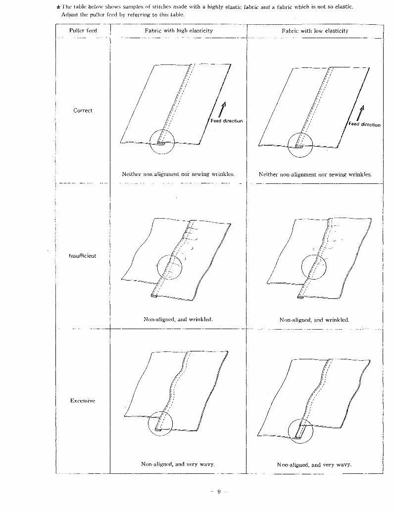
*The table below shows samples of stitches made with a highly elastic fabric and a fabric which is not so elastic. Adjust the puller feed by referring to this table.
Puller feed Fabric with high elasticity Fabric with low elasticity
Correct
Neither non-alignment nor sewing wrinkles. Neither non-alignment nor sewing wrinkles.
Insufficient
Non-aligned, and wrinkled. N on-aligned, and wrinkled.
Excessive
Non-aligned, and very wavy. Non-aligned, and very wavy.
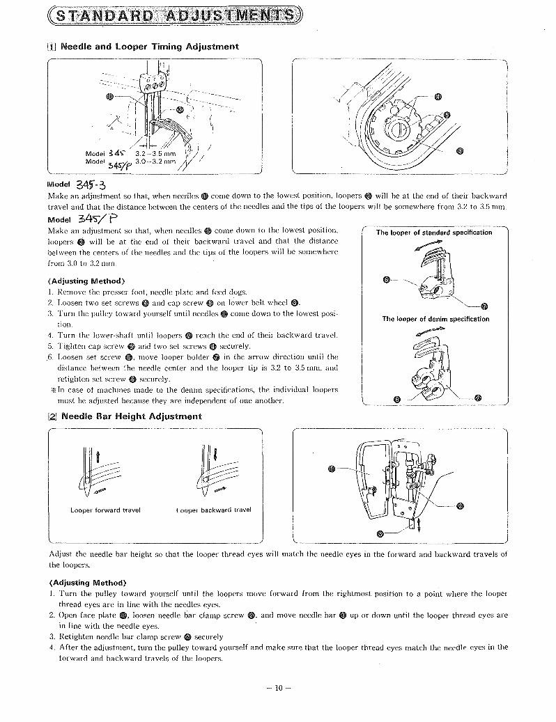
rn Needle and looper Timing Adjustment
( ( ,
.> lr / ' /---1I--/:l/, , /
Model S4"'- 32-35 mm y~) / Model ~4s7f' 3.0-3.2 mm!y /
Model 34f-3 Make an adjustment so that, when needles 0 come down to the lowest position. loopers e will be at the end of their backward travel and that the distance between the centers of the needles and the tips of the loopers will be somewhere from 3.2 to 3.5 mm.
Model 3>4'5'"/ P Make an adjustment so that, when needles 0 come down to the lowest position,
loopers @ will be at the end of their backward travel and that the distance between the centers of the needles and the tips of the loopers will be somewhere
from 3.0 to 3.2 mm.
{Adjusting Method}
1. Remove the presser foot, needle plate and feed dogs. 2. Loosen two set screws e and cap screw 0 on lower belt wheel 8· 3. Turn the pulley toward yourself until needles 0 come down to the lowest posi·
tion.
4. Turn the lower-shaft until loopers e reach the end of their backward travel.
5. Tighten cap screw 0 and two set screws e securely . . 6. Loosen set screw 0, move looper holder 0 in the arrow direction until the
distance between the needle center and the looper tip is 3.2 to 3.5 mm. and
retighten set screw 0 securely.
'* In case of machines made to the denim specifications, the individual loopers
must be adjusted because they are independent of one another.
[2] Needle Bar Height Adjustment
Looper forward travel Looper backward travel
The looper of standard specification
The looper of denim specification
Adjust the needle bar height so that the looper thread eyes will match the needle eyes in the forward and backward travels of the loopers.
(Adjusting Method) 1. Turn the pulley toward yourself until the loopers move forward from the rightmost position to a point where the looper
thread eyes are in line with the needles eyes. 2. Open face plate 0, loosen needle bar clamp screw @, and move needle bar 8 up or down until the looper thread eyes are
in line with the needle eyes.
3. Retighten needle bar clamp screw e securely. 4. After the adjustment, turn the pulley toward yourself and make sure that the looper thread eyes match the needle eyes in the
forward and backward travels of the loopers.
- 10--
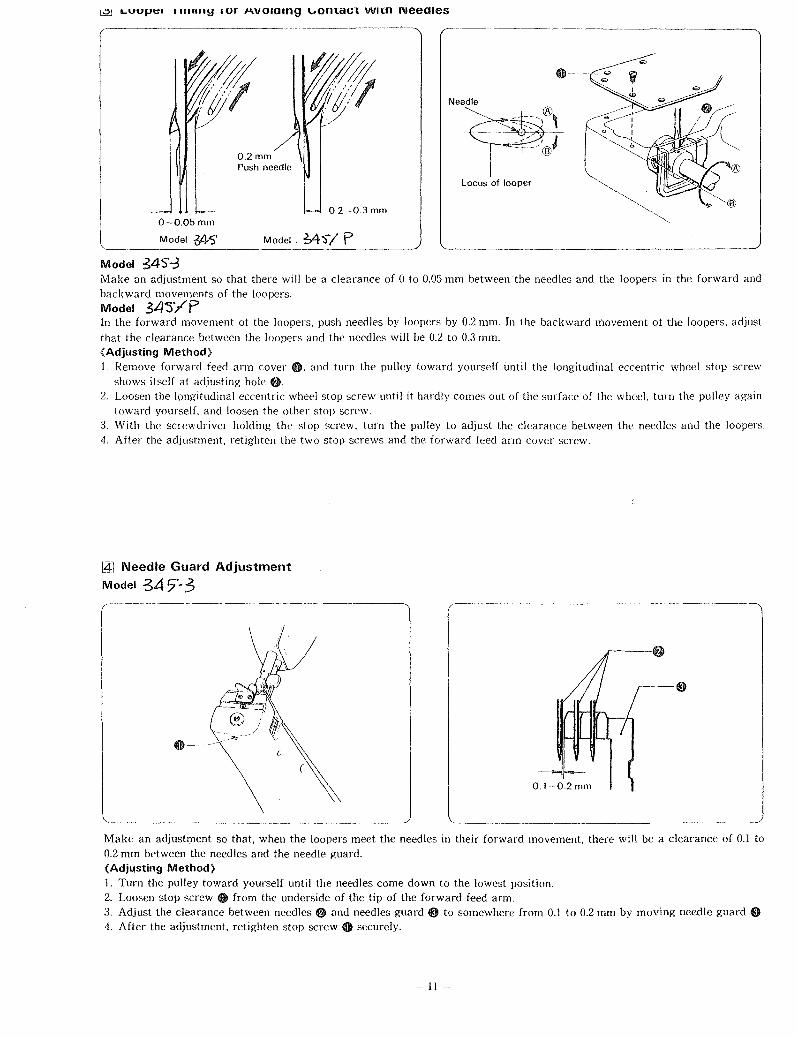
l:2J LVVJ]tH 111111119 lur M.VOlOlng \"onl:aCl: wnn NeeOles
O-O.05mm
Model 34'S'
Model 34S'-;3
O.2mm Push needle
O.2-0.3mm
Model, M'S'/ P
Make an adjustment so that there will be a clearance of 0 to 0.05 mm between the needles and the loopers in the forward and backward movemf'nts of the loopers. Model 34J'/P In the forward movement of the loopers. push needles by loopers by 0.2 mm. In the backward movement of the loopers. adjust that the clearance between the loopers and the needles will be 0.2 to 0.3 mm. (Adjusting Method) 1. Remove forward feed arm cover 0, and turn the pulley toward yourself until the longitudinal eccentric wheel stop screw
shows itself at adjusting hole 6. 2. Loosen the longitudinal eccentric wheel stop screw until it hardly comes out of the surface of the wheel. turn the pulley again
toward yourself. and loosen the other stop screw. 3. With the screwdriver holding the stop screw. turn the pulley to adjust the clearance between the needles and the loopers. 4. After the adjustment. retighten the two stop screws and the forward feed arm cover screw.
I4l Needle Guard Adjustment
Model 347'-3
Make an adjustment so that, when the loopers meet the needles in their forward movement. there will be a clearance of 0.1 to 0.2 mm between the needles and the needle guard. (Adjusting Method) 1. Turn the pulley toward yourself until the needles come down to the lowest position. 2. Loosen stop screw 0 from the underside of the tip of the forward feed arm. 3. Adjust the clearance between needles 8 and needles guard 8 to somewhere from 0.1 to 0.2 mm by moving needle guard 8 4. After the adjustment. retighten stop screw 0 securely.
-11

Model S4 S,/F ~ .. ~---------------~
The clearance between the needles and the tips of the loopers will be 'O.!)5 mm, pushing the needles by needle guard O.
(Adjusting Method)
1. Turn the pulley toward yourself until the needles come down to the lowest position.
2. Loosen stop screw 0. and raise or lower needle guard o so that the bottom ends of the needle eyes will be about '0.5 mm above the bottom of needle guard O.
3. Turn the pulley toward yourself again until the tips of the loopers come to the centers of the needles.
4. Loosen stop screw 0, move needle guard 0 to the left or to the right, and adjust so that the clearance between the needles and the tips of the loopers will be 0.'05 mm, pushing needle points by needle guard O. At this time, please make sure that the clearance between the loopers and the needles is '0.2 ·-0.3 mm in the backward movement of the loopers.
~ Feed Dog Height Adjustment Model 34'S -3 Make an adjustment so that, when feed dog 0 is at the highest position, the feed dog will be '0.8 mm above the top surface of the needle plate. Model ,;4S'"/P Make an adjustment so that the highest part of the feed dog will be 1.2 nun above the top surface of the needle plate.
(Adjusting Method)
Adjusting the feed dog height by turning feed hase eccentric shaft
8·
I§] Puller Height Adjustment Adjust the height of puller 0 so that it is '0.1 to '0.2 mm high from the top of the needle plate.
(Adjusting Method)
Loosen set screw 8, and move puller support @ up or down until puller 0 is 0.1 to '0.2 mm above the top of the needle plate .
.. - 12-
~~'2mm 0.05 mm-·-H+-l-- 0.2 -0.3 mm
-8
l ___ J

[Z] Installing the Spacer (For the denim specifications)
If stitch irregularities develop in sewing very heavy materials, adjust the sub-feed dog to the correct height by spacer-
(Adjusting Method)
1. Remove set screw 0 and sub-feed dog f). 2. Placer spacer ~ under sub-feed dog f) and retighten set
screw O. >Ii The spacer is in the parts box.
~ Thread Release lever Adjustment
[aJ Upper Thread Take-up Thread Guide Adjustment
.-<'-Y;:-;~~Thread -f) "- ( -It il guide
Upper thread W take-up
Model ~4s-~
Model 34"5'-::'
Model Yi.S/p
Make an adjustment so that, when the needle bar is down at the lowest position, the top of the upper thread take-up thread hole meets the bottom of the thread guide.
Model 34s/P Please adjust the distance between the center of the upper thread take-up and the top of the thread guide will be 7-Smm.
(Adjusting Method) 1. Turn the pulley toward yourself until the needle bar is
down at the lowest position. 2. Loosen set screw 4), and move upper thread take-up
thread guide f) up or down until its bottom meets the top of the upper thread take-up 'thread hole.
>liThe higher the upper thread take-up thread guide ~, the greater will be the upper thread loops.
Make an adjustment so that, when the needle bar is down at the lowest position, the thread release lever thread hole meets the thread hole in upper thread tension bracket ~.
(Adjusting Method)
1. Turn the pulley until the needle bar is down at the lowest position. 2. Loosen set screw 0, and raise or lower thread release lever ~ until its thread hole meets the thread hole in upper thread
tension bracket ~. >liThe higher the thread release lever, the tighter will be the stitches.
- 13-

IlQI Thread Release Shaft Adjustment
Make an adjustment so that the thread tension discs will loosen when the presser foot is raised, and tighten when the presser foot is lowered.
(Adjusting Method) 1. Loosen stop screw O. 2. Make an adjustment by turning thread release shaft f)
so that the thread tension discs will begin to loosen when the presser foot is raised 4 mm above the top surface of the needle plate.
3. After the adjustment, retighten stop screw 0 securely.
jgJ lower Thread Take-up Timing Adjustment Make an adjustment so that, when the loopers begin to move backward, lower thread take-up 0 will rise about 5 to 7 mm above lower thread take-up bracket f).
(Adjusting Method) 1. Insert a screwdriver into the adjusting hole in the bed,
and loosen two stop screws $. 2. Raise lower thread take-up 0 5 to 7 mm above thread
take·up bracket f).
3. After the adjustment, retighten two stop screw $.
~ Puller Device Timing Adjustment
1. With 3mm wrench to loosen the screw 0 & ~
2. The timing of the feed will be stsrting when the needle is away from the needle plate about 5 or 6mm, and stoping at lOmm.
3. After adjusting the timing, retighten the screw o &~.
[j] Upper Thread Nippfi}r Adjustment
Adjust the clearance between the upper thread nipper tension bracket and tension plates to somewhere between O.S mm and 1.0 mm.
(Adjusting Method) 1. Loosen stop screw 0, and move upper thread.nipper ten
sion bracket f) in or out until the clearance between it and tension plates $ is somewhere from O.S to 1.0mm.
*Stitch tightness can be improved by narrowing the clear·
r
- 14 -
ance between upper thread nipper tension bracket f) and the arm.

Trouble
-------------, Thread breaks.
Needles break. ._------------'
Stitches skip.
Upper threads loose.
Lower thread tension too
Thread release lever out of
Loopers damaged.
'--___ I"_S_p_e_ctiO_" ___ --'1 [ Remedy
Direction of long groove.
Lower thread tension.
Thread release lever position.
Needle size and thread count.
Refer to instructions for needle installing.
I.~t upper thread l;-l ~_n_. ________ _'__~_J
_~_~J
Smooth loopers with t----------------j sandpaper or buff. L-______________ ~
Needles damaged.
Needles hit loopers.
Needles hit needles guard.
Looper points are dull.
Needle and looper timing
Clearance between needles and loopers too great.
Lower thread take-up timing wrong.
f---------------J Replace needles with good
Clearance between needles and loopers.
----------'
Direction of long groove.
Clearance between needles and needles guard.
Needle size and thread count.
Direction of long groove.
Adjust looper timing to avoid contact with needles.
Refer to instructions for needle installing.
Adjust needles guard.
Refer to the section on "Needle~ and Threads".
Refer to instructions for needle installing.
t----------------l Replace loopers with good
Needle and looper timing.
Clearance between needles and loopers.
Lower thread take-up timing.
Upper thread tension.
Lower thread tension.
Adjust needle and looper timing.
Upper thread take·up thread t----------------j Adjust upper thread take-up guide out of position. thread guide position.
Upper thread nipper does not tighten upper threads. Tension plate clearance.
- 15-
Adjust upper thread nipper.

Trouble
IMachine does not feed ~rk.
Non-alignment and wrinkles IModel-: ~4S"' --:S
Non-alignment and wrinkles IModel-~$4VP
'--___ I_n_sp_e_c_t_io_n. ___ --'I C Remedy I pag~ dog height. dog height.
Pre~ser'foot pre~:ure.l- [J\d)ust presser foot 1 8 I _r~sure. ______ ~
Feed dog worn out.
Presser foot floats and doeS"lI-____ _ not fully press work. ~ ---f~' serviceman check it. L2l
121 I Feed dog and presser toot r-------'--------------ll Have serviceman check work on one side only. them. L-_______ ~ _ __'
Feed dog height incorrect.
Sub feed dog height.
Presser foot pressure.
Adjust sub feed dog height.
Adjust presser foot pressure.
_______ ~-1 Ajust feed dog height. 12 I
~uller timing \\_'_ro_n_g_. __ --'~_; _ti_m_i_n_g_. ___ ~ust p~_device timing. I 14 I . ________ ]-1--' Puller feed. -----t--{AdjUst puller feed. B
Presser foot pressure incorrect.
- 16 -
foot pressure. Adjust presser pressure.
}---1 Adjust feed dog height. 12

CONTENTS
1. CO- MACHINE BODY
2. Cl- UPPER SHAFT MACHANISM
3. C2- NEEDLE BAR MECHANISM
- FEED MECHANISM
4. C3= PULL Y MECHANISM
5. C4- PRESSER BAR MECHANISM
6. C5- LOOPER MECHANISM cr,
7. C6- UPPER THREADING MECHANISM
8. C7". LOWER THREADING MECHANISM
9. C8- LOWER SHAFT MECHANISM
- GAUGE PARTS
10 C9- GAUGE PARTS(F)
11. CI0- GAUGE PARTS(DP)
12. Cll- PULLER DEVICE MECHANISM
13. C12- ACCESSORIES

11
_~ 15
_~ I ---~ ~
I 10
12
I
I CO-1
L'~
co

SP RE PARTS C T LOG --
REF .NO. NAME OF PARTS CO - 1 MACHINE HElD CO - 2 MACHINE REST BOARD CO - 3 LOWER WHEEL SEAT CO - 4 OIL PLUG CO - 5 LOWER WHEEL CO - 6 LOWER WHEEL CONNECTION CO - 7 ONE WAY TRIANGULAR AXLE CO - 8 ONE WAY STILL SPRING CO - 9 ONE WAY STILL BALL CO - 1 0 SCREW 238*6 CO - 1 1 ONE WAY PUSHING PLATE CO - 1 2 FEED DOG PUSHING PLATE LINK CO - 1 3 SCREW 9/64*40 CO - 14 SCREW 11/64*40 CO - 1 5 CHOCK RING (E RING) (
CO - 1 7 LOWER WHEEL SEAT CAP
~-
~~.~~--.---.-.----.--.- -~~~-.------~.-- -
co

24
26
I
I I 19
I
t
Cl

SP RE P RTS C TALOG ------ -----~~~'-~.-' -
REF .NO. NAME OF PARTS C 1 - 1 PULL BAR ENDING SCREW C 1 - 2 VERTICAL PULL BAR C 1 - 3 PULL BAR BEARING C 1 - 4 VERTICAL PULL BAR FIXING SCREW (LOWER) C 1 - 5 PULL BAR SCREW NUT C 1 - 6 UPPER SHAFT C 1 - 7 BEARING 6202 C 1 - 8 UPPER SHAFT BALL BEARING (LEFT) C 1 - 9 OIL STOPPER C 1 - 1 0 BEARING CASE ASSEMBLY C 1 - 1 1 BEARING 6302 C 1 - 1 2 OIL TANK C 1 - 1 3 OIL GAUGE WINDOW C 1 - 1 4 PACKING C 1 - 1 5 OIL GAUGE FLANGE , C 1 - 1 6 OIL TANK PACKING C 1 - 1 7 PACKING C 1 -. 1 8 UPPER WHEEL ECCENTRIC WHEEL C 1 - 1 9 UPPER WHEEL MOVING PULL BAR ("8"TYPE) C 1 - 20 CHOCK RING C 1 - 21 PULL BAR SCREW C 1 - 22 FIXING PULL BAR SCREW WASHER C 1 - 23 PULL BAR SCREW NUT C 1 - 24 THICKNESS ADJUSTING PULL BAR C 1 - 25 PULL BAR FIXING PULL BAR C 1 - 26 UPPER WHEEL CONNECTION C 1 - 27 MOVABLE LEFT-RIGHT CHOCK RING C 1 - 28 CHOCK RING SCREW C 1 - 29 CONNECTION COPPER TUBE C 1 - 30 VERTICAL PULL BAR C 1 - 102 BEARING FIXING SCREW
~-~ .... ----._-_ ... - . ----- ---~------------.. - .. .-----,-_ .
C1

4 3 2 5
I
30 I
1 3 26
I I
2S
/~-10
Cl

SPARE P RTS CAT ALOG ----~---- .
REF .NO. NAME OF PARTS CI-I02-1 BEARING FIXING BUSHING C 1 - X 3 SCREW 7.94 C 1 - X 4 SCREW 7.94 C 1 - X 5 SCREW 3.57 C 1 - X 6 CAP SCREW
C1

---I
10
I J L---
~14
-9
11
C2
X66
2

SP RE P RTS CAT L G --- - - -
REF .NO. NAME OF PARTS C 2 - 1 NEEDLE BAR CRANK C 2- 2 NEEDLE BAR CRANK ROD C 2- 3 NEEDLE BAR BRACKET C2 - 4 WICK C 2- 5 OIL LEAK PROOF CAP C2 - 7 NEEDLE BAR GUIDE SLIDE BLOCK C 2 --.-:. 8 NEEDLE BAR GUIDE C 2- 9 NEEDLE BAR C 2 :- 10 NEEDLE BAR BUSHING (UPPER) C2 - 1 1 NEEDLE BAR BUSHING (LOWER) C 2- 1 2 THREAD TAKE-UP CRANK C 2- 14 OIL CAP C 2- 15 NEEDLE C 2- 1 6 FEED DOG ECCENTRIC AXLE C 2 - 1 7 WASHER ,
C2 - 1 8 ECCENTRIC WHEEL SLEEVE C 2- 1 9 ECCENTRIC WHEEL WITH SCREW C2 - 20 ECCENTR1C WHEEL SLEEVE C 2- 21 FEED BAR SLIDE BLOCK ASSEMBLY C2 - 22 PACKING C2 - 23 FEED LIFTING FORK C2 - 24 FEED BAR SLIDE BLOCK C2 - 25 ECCENTRIC SHAFT C 2- 26 FEED DOG ECCENTRIC SET C2 - X7 SCREW 6.35 C2 - X8 SCREW 437*10 C2 - X9 SCREW 5.95
.-C2 - X10 SCREW 5.95 C2 - XII SCREW 6.35 C2 - X14 FEED ECCENTRIC ADJUSTING SCREW C2 - X15 SCREW 5.95
C2

---, ~14
10 - 9
~-11
I J L---
X66
2
]]7
C2

SPARE P RTS C T LO REF .NO. NAME OF PARTS
C 2- X 1 6 SCREW 437*12 C 2 - X17 SCREW 5.95 C 2- X50 SCREW 357*8 C2 - X60 SCREW 3.75*5 C2 - X66 SCREW 6.35 C 2- Y01 NUT 5.95
C2
--T\
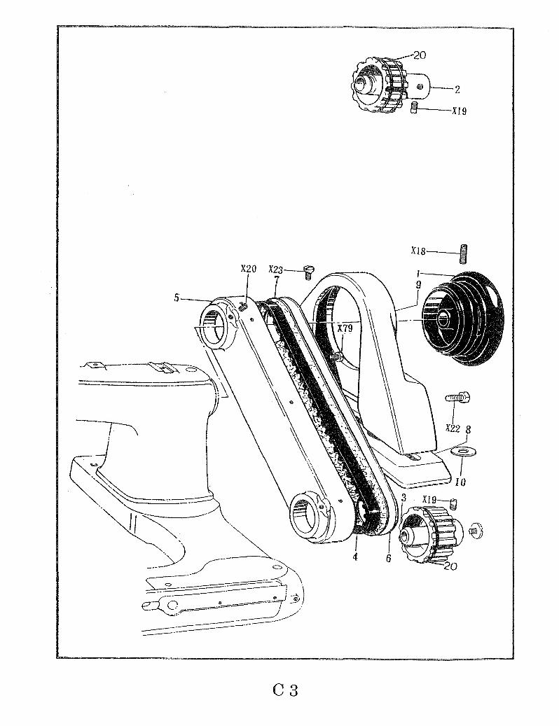
C3
2
--X19
XI8 -I

SP RE PATS C T LOG _. --
REF .NO. NAME OF PARTS C 3- 1 PULLEY C 3- 2 TIMING BELT WHEEL ASSEMBLY (UPPER) C 3- 3 TIMING BELT WHEEL ASSEMBLY (LOWER) C 3 - 4 TIMING BELT C 3 - 5 BELT COVER C 3- 6 BELT COVER PLATE C 3- 7 PACKING C 3- 8 PULLEY COVER BASE C 3 - 9 PULLEY COVER C3 - 10 WASHER C3 - 20 SPRING COIL C 3 - X18 SCREW 5.95 C 3- X19 SCREW 6.35*12 C 3- X20 SCREW 6.35 C3 - X22 SCREW 11.11
'.
C3 - X23 SCREW 6.35 C3 - X79 SCREW 476*8
I
~--~-~-----~---~~-,
C3

18
2
·24----.) 3--l 4_~k
X9 -----m
8
7
9 11 I
- .---~ ~
r------14
C4
5
926 Pl
1-·'
5

SP RE P TS CAT LO ,----- ~~~~~-.. ~~--
REF .NO. NAME OF PARTS C 4 - 1 PRESSER BAR C4 - 2 FACE PLATE UPPER HINGE ASSEMBLY C4 - 3 STEEL BALL C 4- 4 PRESSER BAR BUSHING (UPPER) C4 - 5 PRESSER BAR BUSHING (LOWER) C 4 - 6 FACE PLATE (LOWER) C4 - 7 PACKING C 4- 8 PRESSER BAR CLAMP ASSEMBLY C4 - 9 PRESSER PLATE SPRING C4 - 1 0 PRESSER PLATE SPRING PIN C4 - 11 PRESSER PLATE SPRING ASSEMBLY C4 - 1 2 GUIDE WASHER C4 - 13 WING NUT C4 - 14 PRESSER BAR LIFTER C4 - 1 5 KNEE LIFTER LEVER c
C4 - 16 KNEE LIFTER SPRING C4 - 17 PRESSER FOOT LIFTER CHAIN ASSEMBLY C4 - 1 8 FACE PLATE (UPPER) C4 - 19 STOPPER SPRING PLATE (L) C4 - 20 STOPPER SPRING PLATE (S) C4 - 24 OIL CAP C4 - X9 SCREW 5.95 C4 - X24 SCREW 4.37 C4 - X25 PRESSER ADJUSTING SCREW C4 - X26 STUD SCREW 5.95 C4 - X27 STUD SCREW 7.94 C4 - X31 SCREW 357*10 C4 - X60 SCREW 3.75 C4 - Y02 NUT 4.76
C4

X36~
2~ 12
X28
13
16--
7
@;r---20
X42 r<:I~--21
18
C5
~X38
~Il
14---.:,.
15--~!
X9 X34 5
I !
X8 17 31

SP RE P RTS C TLOG REF .NO. NAME OF PARTS
C 5 - 1 OIL CAP C 5- 2 ECCENTRIC WHEEL SLEEVE C 5- 3 LOOPER FEEDING FORK C 5 - 4 LOOPER FEEDING SHAFT C 5 - 5 LOOPER FEEDING SHAFT RECEIVER C5 - 6 PIN C5 - 7 LOOPER FRONT-REAR TRANSMISSION C5 - 8 SLIDE BROCK SHAFT C5 - 9 LOOPER LEVER SHAFT C 5 - 1 0 PACKING C 5 - 11 LOOPER CONNECTING ROD GUIDE PLATE C5 - 1 2 WASHER C 5 - 1 3 LOOPER SHAFT CLAMP C 5 - 1 4 LOOPER SHAFT C 5- 1 5 LOOPER SHAFT BUSHING (FRONT) "
C 5- 1 6 LOOPER SHAFT BUSHING (REAR) C5 - 1 7 SET COLLAR C5 - 1 8 LOOPER FEED ARM LID ASSEMBLY C 5 -'- 19 PACKING C5 - 20 OIL GAUGE C5 - 21 PACKING C5 - 22 CAP PLATE C5 - 23 PACKING C 5- 24 PACKING C5 - 25 "8" TYPE TRANSMISSION DEVICE C 5 - 26 ECCENTRIC WITH SCREW C5 - 27 EYEPIECE C5 - 28 STEEL BALL C 5 - 29 LOOPER SLIDE BASE C 5 - 30 WICK C 5 - 3 1 LOOPER LEFT-RIGHT MOVING SET
-~.~,.-.-.--.~---~- .. -,
C5

X 3 6-::::;;:1l
2~
X28
13
1
16--.1
~--20
X42 ~--21
18
C5
~X38
~ll
14-----""
15---1

SP RE P RTS C T L· G REF .NO. NAME OF PARTS
C5 - 32 ---------------------------_ ........ -C 5 - 33 ----------,.,.--------------------C5 - 702 SQUARE BALL C5 - X8 SCREW 437*7 C 5 - X9 SCREW 5.95 C5 - X28 SCREW 4.37 C5 - X31 SCREW 3.57 C 5- X32 SCREW 4.37 C 5- X33 SCREW 4.37*10 C5 - X34 SCREW 4.76 C 5 - X35 SCREW 2.38 C5 - X36 SCREW 3.57 C5 - X37 SCREW 4.37 C5 - X38 SCREW 4.37 C 5 - X39 SCREW 5.95 C 5 - X42 SCREW 12.70 C5 - X50 SCREW 357*5 C5 - Y03 NUT 5.95
C5

C6

SP RE P TS C T L G REF .NO. NAME OF PARTS
C6 - 1 UPPER THREAD GUIDE RETAINER C6 - 3 BRACKET C6 - 6 THREAD HANGER C6 - 7 LINE GUIDE DEVICE C6 - 8 TENSION SPRING WASHER C6 - 9 TENDION SPRING WASHER C6 - 10 UPPER THREAD TENSION ADJUSTING NUT C6 - 11 TENSION DISC C6 - 1 2 TENSION DISC PRESSER C6 - 1 3 UPPER THREAD TENSION SPRING C6 - 14 UPPER THREAD RELEASE PIN C6 - 1 5 THREAD RELEASER SHAFT C6 - 16 - - - - - - - - - - - - - - - - - - - - - - -C6 - 1 7 - - - - - - - - - - - - - - - - - - - - - - -C6 - 18 UPPER THREAD TENSION SUTD SCREW C6 - 23 LOWER THREAD TENSION PLATE C6 - 24 PIN C6 - 25 TENSION RELEASE CRANK C6 - 26 TENSION RELEASE CONNECTING BAR C6 - 27 THREAD RELEASER LEVER C6 - 28 THREAD RELEASER LEVER SHAFT C 6- 29 TENSION RELEASE CONNECTING ROD C6 - 30 TENSION RELEASE LINK C6 - 31 TENSION RELEASE SUTD C6 - 32 THREAD GUIDE C6 - 33 WASHER C6 - 34 UPPER THREAD TAKE-UP LEEVER ASSEMLY C6 - 35 THREAD CHECKER C6 - 36 SPRING C6 - 37 LOEWR THREAD GUIDE C6 - 38 WASHER
C6

26---"/
26 25 X47 12
J II
" t, Y04 14
. X48/r 10 8 X59~J ~, X48 ~ ) \.
1
6
1 · -i X46 X44
15 . ~~ /~ 4>
9 7 (:J
44
I X56
~1lJPC ~
(\
0 ____ ---1 ' ~~ .. -'. ',,<:J ® --.. ~I.--.- ::.::::\ \ \ .. ~~ .. ~.~.---,.-; : L.~~;~' /~ .-.. -
150 34 \ ! ~ .... "'-. \.(0'-_
nJi~ \ 1 rli /At-u 2;~ 16 40
\. i!./ (1\ .. e ~ 41 X54 35 .~ 32 33 X53 ~ ~-XlO
36 --5' /?-.o. 37 ". 17 39 ~38 (!J • 23 ~ X49 28 X49 2q--..-.:~
43-~ Y04-~~
C6

Sp· E P RTS C T LOG ,--
REF .NO. NAME OF PARTS C6 - 39 UPPER THREAD TENSION REGULATOR ASSEMBLY C6 - 40 UPPER THREAD TENSION SUTD ASSEMBLY C6 - 41 UPPER THREAD TENSION SPRING C6 - 43 WASHER C6 - 44 UPPER THREAD FASTENING CAM WITH SCREW C6 - XI0 SCREW 5.95 C 6- X44 SCREW 357*5
(
C6 - X46 SCREW 476*20 C6 - X47 SCREW 4.37 C6 - X4-8 SCREW 3,57 C6 - X49 SCREW 3.57*6 C6 - X50 SCREW 3.57 C6 - X51 SCREW 4.76 C6 - X52 SCREW 5.95*6 C6 - X53 SCREW 3.57 C6 - X54 SCREW 2.3"8 C6 - X56 SCREW 5.95 C6 - X58 UPPER THREAD TENSION STUD SCREW C6 - X59 SCREW 4.37 C6 - X65 SCREW 238*4 C6 - Y04 NUT 4.37
C6

2
7
43
C7
19 18
X65 X57

SP RE P RTS CAT L G REF .NO. NAME OF PARTS
C 7 - 1 LOWER THREAD GUIDE RETAINER C 7 - 2 UPPER COVER C 7 - 3 BRACKET C 7 - 4 MACHINE REST BOARD C 7 - 5 FIXING SEAT C 7 - 6 LOWER THREAD GUIDE SUPPORTER C 7 - 7 FIXING PIN C7 - 10 LOWER THREAD COVER C7 - 11 PLATE SPRING C7 - 1 2 LOWER THREAD GUIDE HINGE ASSEMBLY (L) C 7 - 13 LOWER THREAD GUIDE HINGE ASSEMBLY (R) C 7 - 1 4 LOOPER CONNECTOR GUIDE PLATE C 7 - 1 6 THREAD KEEPER C 7 - 1 7 HORIZONAL THREAD GUIDE PLATE C7 - 1 8 HORIZONAL TUBULAR GUIDE PLATEtSPRING C 7 - 1 9 POSITON PLATE C 7 - 20 LOWER THREAD TENSION BRACKET C 7 -" 21 LOWER THREAD C7 - 22 LOWER THREAD TENSION NUT ASSEMBLY C 7 - 23 LOWER THREAD TENSION PLATE C 7 - 24 PIN C 7 - 25 LOWER THREAD TENSION SPRING C 7 - 27 THREAD TAKE-UP LEVER COVER C7 - 28 SPRING C 7 - 29 LOWER THREAD TAKE-UP LEVER FRAME C 7 - 30 LOWER THREAD TAKE-UP LEVER COVER SHAFT C 7 - 31 LOWER THREAD TAKE-UP LEVER BASE C7 - 32 GUIDE PLATE C 7 - 33 WASHER C 7 - 34 LOWER THREAD GUIDE PLATE C7 - 35 SCREW
~-------~~----~---------~-- ----
C7

X57
2
2728 X64
7
19----I[;J ] 18 .. 14
43
. ~ -
X71 " ---tt :=:: r .- X65 44 X6S <» ~ L I iJ 17 _ k)4~' v-X44
IIfi: '.' """ '. . . :~' ,,\ , r 11 ,~~~'5 ,(rm "'J~ i) "I- X65
m}!clCJ1U I ~::W) 10 I 12 X31-1 12
d ~ ~cl~ 50
C7

SP RE PARTS C T LO r--- .
REF .NO. NAME OF PARTS C7 - 36 WASHER C7 - 37 LOWER THREAD GUIDE (LEFT) C7 - 39 LOWER THREAD GUIDE (RIGHT) C7 - 40 LOWER THREAD GUIDE (LEFT) C7 - 41 LOWER THREAD GUIDE PLATE C7 - 42 PIN C7 - 43 PIN C7 - 44 LOWER THREAD TAKE-UP DISC ASSEMBLY C7 - 45 LOWER THREAD FEED TUBE C7 - 46 LOOPER THREAD GUIDE BRACKET C7 - 47 LOOPER THREAD GUIDE BRACKET C7 - 48 THREAD CUTTER GUIDE PLATE C7 - 49 THREAD CUTTER C7 - 50 LOOPER SIDE COVER (RIGHT) C7 - 51 LOOPER SIDE COVER (LEFT) C7 - 52 SPRING C7 - 53 LOOPER GUIDE C7 - 55 LOWER rHREAD GUIDE C7 - X5 SCREW 357*14 C7-X31-1 SCREW 357*10 C7 - X44 SCREW 357*5 C7 - X45 SCREW 9/64*40 C7 - X50 SCREW 3.57 C7 - X52 SCREW 5.95*6 C7 - X57 SCREW 2.38 C7 - X60 SCREW 357*4 C7 - X61 LOWER THREAD TENSION ADJUSTING SCREW C7 - X62 SCREW 357*6 C7 - X63 SCREW 5.95*16 C7 - X64 SCREW 2.38 C7 - X65 SCREW 238*4
~
C7

21
4.3
7
X67 48 49~J 45 ~ hj~ X5~
4-6 ~~X69 X5~'"
~?--;., t\"tt~
2
22. ~j .., 53
...-- 1~3 ~ X73 55
2023~;J X61
C7
X68 X60
19----fE] 14 18 It
X57
X64

SP RE P RTS C T LOG REF .NO. NAME OF PARTS
C7 - X66 SCREW 6.35 C 7- X67 SCREW 238*6 C7 - X68 SCREW 4.37 C7 - X69 SCREW 318*6 C7 - X71 SCREW 2.38*4 C7 - X73 SCREW 357*14
<
---~
C7

rill =
X7S
2
102
X76 ~ I 0 0 . 7.,..1 • 7-2
~X5 ~~-----12
0
8
8-1 8-2
I
]
I 1
3 4 x 2
~13 ~ .
~X81
6~
5
X78 9
f ~
X78
~
9-1 9-2
~15
~13-1 13-2
10 • 0 ~X81
C8
),
-~
10-1 10-2
X3
14 X82
\ 'i -,- ~
... -~

SP RE P RTS C T L G REF .NO. NAME OF PARTS
C 8- 1 LOVER SHAFT C8 - 2 BEARING 6200 Z C 8- 3 BEARING 6201 Z C 8- 4 BALL BEARING BUSHING C 8- 5 BEARING CASE ASSEMBLY C8 - 6 BEARING FIXING BUSHING C8 - 7 NEEDLE CLAMP WITH SCREW C8 - 7- 1 NEEDLE CLAMP WITH SCREW 1/4 C 8- 7 - 2 NEEDLE CLAMP WITH SCREW 3/16 C 8- 8 NEEDLE PLATE C8 - 8- 1 NEEDEL PLATE 1/4 C8 - 8 - 2 NEEDEL PLATE 3/16 C 8- 9 . PRESSER FOOT ASSEMBLY C 8- 9 - 1 PRESSER FOOT ASSEMBLY 1/4 C8 - 9 - 2 PRESSER FOOT ASSEMBLY 3/16 ,
C 8- 1 0 FEED DOG C8-10-1 FEED DOG 1/4 C8 -. 10- 2 FEED DOG 3/16 C 8- 11 BEARING 6302 C 8 - 12 LOOPER HOLDER ASSEMBLY C 8 - 13 NEEDLE GUARD C8-13-1 NEEDLE GUARD 1/4 C8-13-2 NEEDLE GUARD 3/16 C8 - 1 4 LAP PER ASSEMBLY C8 - 1 6 LOOPER SHORT C8 - 1 7 LOOPER MEDIUM C8 - 1 8 LOOPER LONG C8 - 102 BEARING FIXING SCREW C 8- X3 SCREW 7.94 C 8- X5 SCREW 357*16 C8 - X8 SCREW 437*10
C8

r[l~
X75
2
102
X16~ I 0 0 . 7-1 J, 7-2
~~·J----12
o
8-1 8-2
I
:]
~13 W ~X81
I 1
X78
[ ~
X78 l
t)mll
C8
9
9-1 9-2 I
5
~15
[t:13-J 13-2
10
io ~X8J
10-1 10-2

SP RE P RTS C TALOG REF .NO. NAME OF PARTS
C8 - X32 SCREW 4.37 C8 - X74 SCREW 6.35 C8 - X75 SCREW 4.37 C8 - X76 SCREW 4.37 C 8- X77 SCREW 4.37 C8 - X78 SCREW 3.57*8 C8 - X79 SCREW 4.76 C 8- X81 SCREW 3.57 C8 - X82 SCREW 3.57
(
'"
C8

p I-lJ I
X93
2
'---3
5 X86
hl X94
X92 X31'-1
l/~ @t-~~5 ~
'iiil--_ X91 X79
1 t _.--1
17
20_~,...~
19 -_-¥"'
21---¥'
~l!
18
C9

SP REP RTS C T LOG REF .NO. NAME OF PARTS
C 9 - 1 NEEDLE CLAMP ASSEMBLY C9 - 2 NEEDLE PLATE C9 - 3 PRESSER FOOT ASSEMBLY C9 - 5 PRESSER FOOT (F) SPRING C9 - 6 PRESSER FOOT ASSEMBLY C9 - 7 SUB FEED DOG C9 - 9 FEED DOG C9 - 11 NEEDLE GUARD C9 - 14 LAPPER ASSEMBLY C9 - 15 NEEDLE GUARD BRACKET C9 - 1 6 LOOPER (SHORT) C9 - 1 7 LOOPER (MIDDLE) C9 - 18 LOOPER (LONG) C9 - 19 LOOPER HOLDER (SHORT) C9 - 20 LOOPER HOLDER (MIDDLE) (
C 9 ....,.. 21 LOOPER HOLDER (LONG) C9- X31-1 SCREW 357*10 .
C9 - X77 SCREW 4.37 C9 - X79 SCREW 4.76 C9 - X82 SCREW 3.57 C9 - X83 PIN C9 - X86 SCREW 2.38 C9 - X91 SCREW 1.98 C9 - X92 SCREW 3.57 C9 - X93 SCREW 3.18 C9 ~ X94 SCREW 5.95 C9 - Y05 NUT 3.57
C9

I-j r X93
2
X92
I X31-1
1 ~15 ®ID ~ ~ @1-Y05
20-~
19--~...-::'I 21"-----;;:
CIO
~1
X90~

SP RE P RTS C T LOG -
REF .NO. NAME OF PARTS C 10 - 1 NEEDLE CLAMP ASSEMBLY C 10 - 2 NEEDLE PLATE C 10 - 3 SPRING M C 10 - 4 SPRING F C 10- 5 SPRING BL C 10 - 6 PRESSER FOOT ASSEMBLY C 10- 7 SUB FEED DOG C 10- 8 NUT 3.18 C 10 - 9 FEED DOG C 10- 1 0 SPRING BS C 10 - 1 1 NEEDLE GUARD C 10 - 14 LAPPER ASSEMBLY C 10 - 1 5 NEEDLE GUARD BRACKET C 10 - 1 6 LOOPER (SHORT) C 10- 17 LOOPER (MIDDLE) ,
C 10 - 1 8 LOOPER (LONG) C 10- 19 LOOPER HOLDER (SHORT) C 10 - 20 LOOPER HOLDER (MIDDLE) C 10 - 21 LOOPER HOLDER (LONG) C10-X31-1 SCREW 357*10 C 10 - X77 SCREW 4.37 C 10 - X79 SCREW 4.76 C 10- X82 SCREW 3.57 C 10 - X84 STUD SCREW C 10 - X85 SCREW 2.38*3.5 C 10 - X86 SCREW 2.38 C 10 - X87 SCREW 318*5 C 10 - X88 SCREW 3.18 C 10 - X89 SCREW 2.38 C 10 - X90 SCREW 3.57*8 C 10 - X91 SCREW 1.98
CIO

DP
~
l~ r X93
X84
X92
/J3H 1 ~15 ®ro~~ @-Y05
~r-X91 X79
~7 I Ef
_---1
~l
17
20-~
19-----"F""_"""-21
CIO
X90~
j 6
Ej1 X89

8P RE P T8 C T ALO REF .NO. NAME OF PARTS
C 10- X92 SCREW 3.57 C 10 - X93 SCREW 3.18 C 10 - Y05 NUT 3.57
.'
(
CIO

14A A
23A_-..... _ <0 23
15A-. ~16A --a es t __ . -- --l
- - . G _ c::::;::l .. -- - t~ I I ~_ (l\ £0 ~_. «> 17A 22A--C -.$I~ W I
\ 19A 21A 20A
C 11
9A I
-_=_'�J

18
lA
! 0 i
\ 0,....... \ . ~
3
14A 23A_-....., (0 23A
15A--:-- ~16A --a .- t _-, -- ~ r·--:--m ·~~~o-c:r I ~- ~. 17A :z.v..--c: - !$!JI~ I
I 19A 21A lOA
C 11

SP RE PARTS CATALOG REF .NO. NAME OF PARTS
C 11 - 1 PRESSURE ADJUSTING SCREW C 11 - 2 UPPER WHEEL PRESSER BAR C 11 - 3 SPRING C 11 - 4 FIXING DEVICE SCREW C 11 - 5 WHEEL DIRECTION FIXING DEVICE C 11 - 6 PRESSER ROD BUSHING C 11 - 7 UPPER WHEEL SEAT C 11 - 8 UPPER WHEEL CONNECTON C 11 - 9 ONE WAY PULL HOLDER C 11 - 10 SCREW C 11 - 11 NUT C 11 - 1 2 ONE WAY TRIANGULAR WHEEL C 11 - 1 3 UPPER WHEEL C 11 - 1 4 ONE WAY STILL BALL C 11 - 1 5 ONE WAY STILL SPRING (
C 11 - 1 6 TRIANGULAR AXLE FIXING SCREW C 11 - 1 7 CHOCK RING C 11 - 1 8 FACE PLATE (UPPER) C 11 - 1 9 SCREW ell - 1A PRESSURE ADJUSTING SCREW C 11 - 2A NUT C 11 - 3A PRESSER FOOT LIFTER C 11 - 4A STUD SCREW ell - 5A SPRING C 11- 6A PRESSER BAR GUIDE ASSEMBLY C 11 - 7A SCREW C 11 - 8A ROLLER PRESSER BAR LIFTER C11 - 9A SCREW C 11 - lOA PRESSER ROD BUSHING C 11 - 11A SCREW ell - 12A UPPER WHEEL PRESSER BAR
C 11

SP RE; P RTS C' T LO REF .NO. NAME OF PARTS
C 11 - 13A SCREW C 11 - 14A PULLER SUPPORTER ASSEMBLY C 11 - 15A SCREW C 11 - 16A ONE WAY PULL HOLDER C 11 - 17A UPPER WHEEL CONNECTON C 11 - ISA FACE PLATE C 11 - 19A ONE WAY TRIANGULAR WHEEL C 11 - 20A UPPER WHEEL C 11 - 21A ONE WAY STILL BALL C 11 - 22A ONE WAY STILL SPRING C 11 - 23A SCREW
C 11

11 12
t
lJ 7 8
j~
1 15
C12

SP RE P RTS C T LOG REF .NO. NAME OF PARTS
C 12 ~ 1 THREAD STAND C 12 - 2 CUSHION ASSEMBLY C 12 - 3 BASE CUSHION C 12- 4 HEAD COVER C 12 - 5 OIL TANK C 12 - 6 OILER ASSEMBLY C 12- 7 NEEDLE C 12- 8 TWEEZERS C 12 - 9 SPANNER C 12 - 1 0 SPANNER C 12 - 11 SCREW DRIVER C 12- 1 2 SCREW DRIVER C 12 - 13 SCREW DRIVER C 12 - 14 THREADLE C 12- 1 5 SPACER < THREAD TR I MMER )
,
C 12- Xl SCREW 6.35 C 12- X2 SCREW 6.2*26 C 12- X22 SCREW 11.11 C 12 - X23 SCREW 6.35
C12

MAIN office
131 W. 25th Street
New York, NY 1000 I
Tel: 212-741-7788
Fax: 212-741-7787
e-mail: [email protected]
Consolidated Sewing Machine Corp. Website: www.consew.com
Miami,FL
4013 N.W. 79th Avenue
Miami, FL 33166
Tel: 305-471-0200
Fax: 305-471-0243
e-mail: [email protected]
Los Angeles, CA
2320 South Hill Street
Los Angeles, CA 90007
Tel: 213-745-8844
Fax: 213-745-8855
e-mail: [email protected]