model based document and report generation for … · model based document and report generation...
TRANSCRIPT

Model Based Document and Report Generation forSystems Engineering
Christopher Delp, Doris Lam, Elyse Fosse, Cin-Young LeeJet Propulsion Laboratory, California Institute of Technology
4800 Oak Grove DrivePasadena, CA 91109
(818)[email protected]
Abstract—As Model Based Systems Engineering (MBSE) prac-tices gain adoption, various approaches have been developedin order to simplify and automate the process of generatingdocuments from models. Essentially, all of these techniques canbe unified around the concept of producing different views ofthe model according to the needs of the intended audience. Inthis paper, we will describe a technique developed at JPL ofapplying SysML Viewpoints and Views to generate documentsand reports. An architecture of model-based view and documentgeneration will be presented, and the necessary extensions toSysML with associated rationale will be explained. A survey ofexamples will highlight a variety of views that can be generated,and will provide some insight into how collaboration and inte-gration is enabled. We will also describe the basic architecturefor the enterprise applications that support this approach.
TABLE OF CONTENTS
1 MBSE AND THE STATE OF THE PRACTICE OFDOCUMENT GENERATION . . . . . . . . . . . . . . . . . . . . . . . 1
2 THE PRINCIPLE OF COMMUNICATION . . . . . . . . . . 23 ARCHITECTURE FOR EXTENDING SYSML
VIEWPOINT AND VIEW . . . . . . . . . . . . . . . . . . . . . . . . . . 24 MODEL BASED ENGINEERING ENVIRONMENT . 65 REALIZING SOFTWARE AND APPLICATIONS . . . 86 CONCLUSION . . . . . . . . . . . . . . . . . . . . . . . . . . . . . . . . . . . . 10
ACKNOWLEDGMENTS . . . . . . . . . . . . . . . . . . . . . . . . . . . 10REFERENCES . . . . . . . . . . . . . . . . . . . . . . . . . . . . . . . . . . . . 10BIOGRAPHY . . . . . . . . . . . . . . . . . . . . . . . . . . . . . . . . . . . . . 11
1. MBSE AND THE STATE OF THE PRACTICEOF DOCUMENT GENERATION
Several projects at JPL have now embraced Model BasedSystems Engineering (MBSE). As a result, JPL has de-veloped an institutional approach to MBSE. This approachis based on Systems Modeling Language (SysML) [1] andformal ontology expressed in the terminology and lexicon ofeach engineering domain. MBSE promises to alleviate thedifficulty systems engineers face in communicating acrossengineering disciplines primarily in terms of completenessand consistency. By describing these systems in a formalway using domain specific terms, models can be checkedfor completeness and consistency. These models can also beanalyzed to answer questions about the system such as inputto simulations or other engineering analysis.
At the core of realizing these benefits is effective commu-
978-1-4673-1813-6/13/$31.00 c©2013 IEEE.1 IEEEAC Paper #2233, Version 2, Updated 5/1/2013.
nication between Systems Engineers and other engineeringdisciplines. Since other engineering disciplines are not versedin Systems Engineering models, Systems Engineers still needto produce documents and reports as the primary way to com-municate with stakeholders and other engineering disciplines.One of the keys to MBSE adoption at JPL has been thepractice of generating documents from systems engineeringmodels. This allows systems engineers to easily update andensure consistency among a set of documents as updates aremade to the model.
This document generation technique originated from otherJPL efforts including Ops Revitalization [2]. Since theseinitial innovations, MBSE at JPL has flourished in a numberof projects. In particular, the Ops Revitalization Task [3], theEuropa Study [4] and the Integrated Model-Centric Engineer-ing effort [5] have been crucial drivers for the developmentof models, architecture, technology, and applications thatprovide this capability.
As MBSE practice has begun to move into the mainstream,several homegrown approaches have been developed aroundthe use of the DocBook standard for publishing [6]. In gen-eral, these approaches involve the use of a SysML profile forDocBook to produce a model of a document. The documentmodel is then linked to other SysML models and diagrams toproduce the document.
These approaches are effective at generating the basic struc-ture of the document with injected model information. How-ever, they lack the semantics and patterns to describe how themodel is projected into a document structure. Each existingimplementation has attempted different ways to support this,but none of these applications provides a comprehensive setof capability. They also lack a more fundamental conceptand foundational support for describing how to extract infor-mation from the model in such a way so that analysis andediting of that information can be integrated with externalapplications.
MGSS Ops Revitalization [7] and the Europa Mission Study[8] have deployed full-scale project models in SysML. Sev-eral other efforts across industry are engaged in MBSE with asimilar scale of modeling effort [9]. Modeling at an enterprisescale requires enterprise computing environment capable ofsupporting collaboration among a variety of users workingwith large models and data sets. Web technologies have beenused extensively in these efforts to realize such a scalableenterprise computing environment.
This paper describes the fundamental concept of Viewpointand View as the foundation for providing a comprehensivecapability for generating Views of models. The architecturefor Viewpoint and View and its extensions in SysML are
1

described using examples from the projects at JPL sponsoringthis work. Models of this size require enterprise scalability.Finally we describe the current implementation of a ModelBased Engineering Environment and the document genera-tion support and applications for generating documents andreports for Systems Engineering.
2. THE PRINCIPLE OF COMMUNICATIONSystems Engineers and Architects produce products that mustcommunicate with a diverse group of customers includingdifferent engineering disciplines, managers, organizationaland business roles. This diverse group each has a differentpoint of view with respect to how they understand the system.This motivates a principle of communication that will ensurethat the system is described from each the point of view ofeach of these stakeholders. 2-way communication assertsthat person communicating report what they heard the otherperson request as well as there response. The ISO/IEC 42010[10] definition of Viewpoint and View is consistent withthis principle. Viewpoint and View can be used to providea platform that can describe different aspects of a modelaccording to the rules for describing those different aspectsof the model. Viewpoint describes what the stakeholder pointof view and View represents the depiction of the model of thesystem according to the Viewpoint.
Figure 1. Metamodel of Basic Viewpoint and View
Generating documents and reports using Viewpoints andViews has been demonstrated at JPL as an effective wayto communicate across disciplines using models to ensurecompleteness and consistency of the system architecture anddesign. The current technique employed at JPL uses SysMLViewpoint and View to specify a model for communicatingdifferent aspects of a system model. The SysML defini-tions of Viewpoint and View are consistent with ISO/IEC42010. Figure 1 illustrates the basic semantics for relatingelements of the model to the model View. The conformancerelationship expresses the requirement that the View of themodel be consistent with the methods and rules expressedby the Viewpoint. It is often necessary to communicate acertain set of Views in a particular order. These collectionscan be represented as familiar document structures such assections and subsections in a document as well as slides,tables, worksheets or other forms typical in office reportingsoftware.
The semantics of Viewpoint and View are represented mathe-matically by stating that a Viewpoint morphs the elements ofa model into contents of the View as seen in Figure 2.
If VP is defined to be the homomorphism that represents aviewpoint then:
VP : D(VP) → R(VP)
where D(VP) is the set of integrated model elements thatare within scope for the Viewpoint (e.g., the domain of theViewpoint) and R(VP) is set of view elements that is theimage of D(VP). (e.g., the range of the Viewpoint). It followsthen that:
View : {VP(ME) : ME in D(VP)}
where ME corresponds to a model element. In other words, aViewpoint is the homomorphism that transforms a subset ofmodel elements into View elements.
Figure 2. Mathematical representation of Viewpoint andView
Representing Viewpoint and View mathematically providesa theoretical foundation for the semantics - the implicationbeing that the mathematical theory provides constraints forthe implementation.
3. ARCHITECTURE FOR EXTENDING SYSMLVIEWPOINT AND VIEW
Using the Viewpoint and View definitions in SysML it is pos-sible to define a model of Views that will provide a linearizeddescription of models referenced by the Views. SysMLViewpoint and View have roots in ISO/IEC 42010 so mostof the elements in SysML come directly from the ISO/IEC42010 meta-model. The current SysML implementation doesnot treat all of these elements as first-class model elements.Table 1 identifies the concepts in SysML related to Viewpointand how they are expanded to facilitate View generation.
Models, Views and Viewpoints
Most MBSE practitioners at JPL link their Views togetherto linearize a particular description of a model or models.Modeling the relationships between Views in this way allowsfor a clickable navigation through the model as well asprovides a structure that can be used to generate documentsand other formatted output based on the content of the model.
Figure 3 illustrates how Views can be linked together withdependencies to model the precedence order for reading theViews. Views import models of any sort or type. Thesemodels may be SysML models, ontologies, structured datafrom a database or website, and notional illustrations, justto name a few. In principle, the Viewpoint is even capableof describing Views that exist outside of software, such asrenderings from a 3D printer or clay models of a conceptautomobile or building.
2
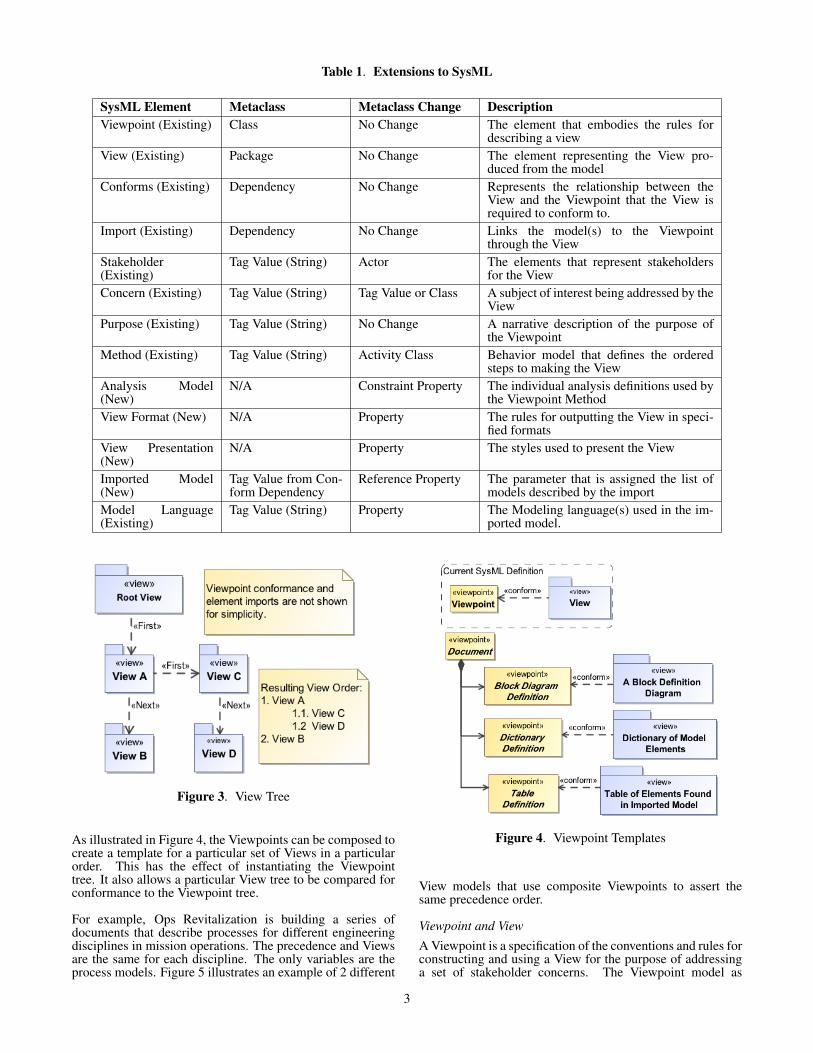
Table 1. Extensions to SysML
SysML Element Metaclass Metaclass Change DescriptionViewpoint (Existing) Class No Change The element that embodies the rules for
describing a viewView (Existing) Package No Change The element representing the View pro-
duced from the modelConforms (Existing) Dependency No Change Represents the relationship between the
View and the Viewpoint that the View isrequired to conform to.
Import (Existing) Dependency No Change Links the model(s) to the Viewpointthrough the View
Stakeholder(Existing)
Tag Value (String) Actor The elements that represent stakeholdersfor the View
Concern (Existing) Tag Value (String) Tag Value or Class A subject of interest being addressed by theView
Purpose (Existing) Tag Value (String) No Change A narrative description of the purpose ofthe Viewpoint
Method (Existing) Tag Value (String) Activity Class Behavior model that defines the orderedsteps to making the View
Analysis Model(New)
N/A Constraint Property The individual analysis definitions used bythe Viewpoint Method
View Format (New) N/A Property The rules for outputting the View in speci-fied formats
View Presentation(New)
N/A Property The styles used to present the View
Imported Model(New)
Tag Value from Con-form Dependency
Reference Property The parameter that is assigned the list ofmodels described by the import
Model Language(Existing)
Tag Value (String) Property The Modeling language(s) used in the im-ported model.
Figure 3. View Tree
As illustrated in Figure 4, the Viewpoints can be composed tocreate a template for a particular set of Views in a particularorder. This has the effect of instantiating the Viewpointtree. It also allows a particular View tree to be compared forconformance to the Viewpoint tree.
For example, Ops Revitalization is building a series ofdocuments that describe processes for different engineeringdisciplines in mission operations. The precedence and Viewsare the same for each discipline. The only variables are theprocess models. Figure 5 illustrates an example of 2 different
Figure 4. Viewpoint Templates
View models that use composite Viewpoints to assert thesame precedence order.
Viewpoint and View
A Viewpoint is a specification of the conventions and rules forconstructing and using a View for the purpose of addressinga set of stakeholder concerns. The Viewpoint model as
3
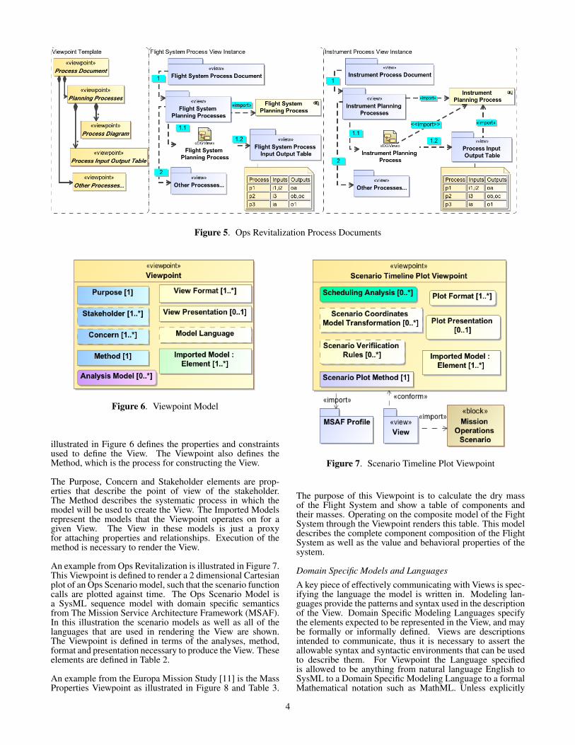
Figure 5. Ops Revitalization Process Documents
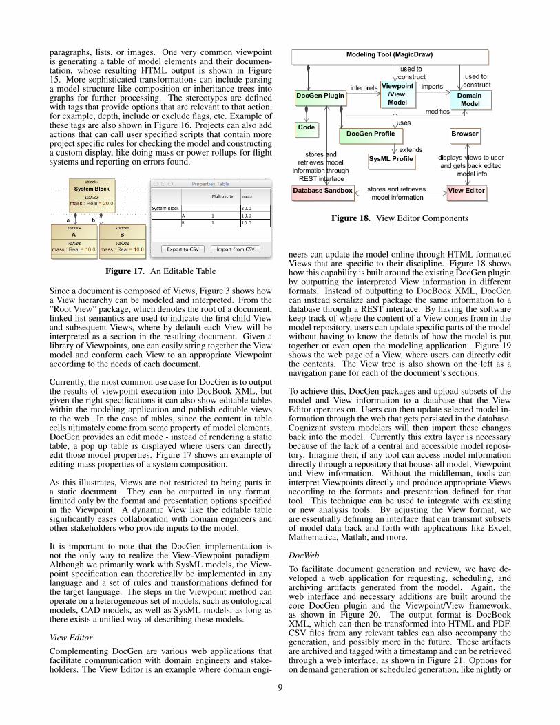
Figure 6. Viewpoint Model
illustrated in Figure 6 defines the properties and constraintsused to define the View. The Viewpoint also defines theMethod, which is the process for constructing the View.
The Purpose, Concern and Stakeholder elements are prop-erties that describe the point of view of the stakeholder.The Method describes the systematic process in which themodel will be used to create the View. The Imported Modelsrepresent the models that the Viewpoint operates on for agiven View. The View in these models is just a proxyfor attaching properties and relationships. Execution of themethod is necessary to render the View.
An example from Ops Revitalization is illustrated in Figure 7.This Viewpoint is defined to render a 2 dimensional Cartesianplot of an Ops Scenario model, such that the scenario functioncalls are plotted against time. The Ops Scenario Model isa SysML sequence model with domain specific semanticsfrom The Mission Service Architecture Framework (MSAF).In this illustration the scenario models as well as all of thelanguages that are used in rendering the View are shown.The Viewpoint is defined in terms of the analyses, method,format and presentation necessary to produce the View. Theseelements are defined in Table 2.
An example from the Europa Mission Study [11] is the MassProperties Viewpoint as illustrated in Figure 8 and Table 3.
Figure 7. Scenario Timeline Plot Viewpoint
The purpose of this Viewpoint is to calculate the dry massof the Flight System and show a table of components andtheir masses. Operating on the composite model of the FightSystem through the Viewpoint renders this table. This modeldescribes the complete component composition of the FlightSystem as well as the value and behavioral properties of thesystem.
Domain Specific Models and Languages
A key piece of effectively communicating with Views is spec-ifying the language the model is written in. Modeling lan-guages provide the patterns and syntax used in the descriptionof the View. Domain Specific Modeling Languages specifythe elements expected to be represented in the View, and maybe formally or informally defined. Views are descriptionsintended to communicate, thus it is necessary to assert theallowable syntax and syntactic environments that can be usedto describe them. For Viewpoint the Language specifiedis allowed to be anything from natural language English toSysML to a Domain Specific Modeling Language to a formalMathematical notation such as MathML. Unless explicitly
4

Table 2. Scenario Viewpoint Elements
ViewpointElement
Description
SchedulingAnalysis
This analysis reasons out the temporalordering from the model
ScenarioCoordinatesModel Trans-formation
Transformation from SysML Scenariomodel to trajectories in 2D coordi-nates
Scenario Veri-fication Rules
Completeness and Correctness rulesfor verifying
Scenario PlotMethod
The order for executing each analysisthat ultimately produces the View
Figure 8. Mass Properties Table Viewpoint
prohibited, natural language documentation and narration arealways expected to be included.
An example of a Domain Specific Modeling Language canbe found in the Ops Revitalization project at JPL. Ops Re-vitalization has developed the Mission Service ArchitectureFramework (MSAF) [3] for the purposes of modeling Mis-sion Operations Systems. The MSAF is a set of modelingelements and relationships for describing the interfaces, func-tions and process that make up an MOS using the lexicon ofMission Operations. The MSAF also defines patterns thatreflect the allowable combinations of these domain specificterms. The MSAF is a Domain Specific Modeling Languageand as such is built as an extension to BPMN (BusinessProcess Modeling Notation) and SysML. Viewpoints definedfor the Ops Revitalization Task are typically specified in thelanguage of the MSAF, however sometimes SysML or BPMNare used.
Model Analysis
In order to generate a View of a model, it is necessary to an-alyze the model. The Viewpoint also defines a set of analysisthat can be specified. These rules provide the means to checkand/or operate on the model as part of creating the View. This
Table 3. Mass Properties Viewpoint Elements
ViewpointElement
Description
CompositeMassConstraint
The constraint that asserts that themass of a component is the sum of themasses of its child components
ComponentTree ModelTransforma-tion
Model Transformation that transformsthe SysML flight system model into atree of flight system components
Value TreeModel Trans-formation
The model transformation that trans-forms the flight system model into atree of mass properties
ComponentPropertiesTable Map
The model transformation that trans-forms the flight system model into amap of the trees described above
Mass Analy-sis Method
The ordered steps for performing themass analysis
property can be used to describe any kind of analysis to beperformed on the Model. Some common uses include modelquerying and filtering, asserting model verification, assertingmathematical formulae, and model transformations. Theseexamples illustrate the broad range of the types of analysisthat can be defined as part of the Viewpoint. It is importantto note that the Method property described later defines howthese different suites of rules may be applied in the course ofgenerating the View.
The Europa study has found utility in this aspect of theViewpoint [12]. The Viewpoints for the Flight System MassEquipment List (MEL) define tables that describe the massneeds and constraints for the Mission. Using the modelof a candidate Flight System, these Viewpoints are used torender a View of the Flight System in terms of the MEL. TheViewpoint defines analysis for verifying the correctness of themodel, verifying the mass calculation, and transforming themodel into a simpler model of hierarchical components andmass properties.
Transforming the model into a simpler model of hierarchi-cal components and mass properties is an example of anAnalysis that performs a Model Transformation. The EuropaFlight System Model is built in SysML. It has a hierarchicalcomponent structure decorated with many properties andbehaviors. In order to calculate the mass of a Flight System,the Flight System Model is transformed into a simpler modelthat consists of components, mass constraints, and massproperties. This new structure can then be used to solve themass constraints and calculate the mass of the Flight Systemas defined in the Mass Calculation analysis.
Another analysis example from Ops Revitalization involvespattern analysis. The MSAF mentioned earlier describes thefundamental architectural patterns for a Mission OperationsSystem. Viewpoints defined for the MSAF all include rulesthat verify usages of the framework patterns. These rulescompare models that have been built using the MSAF andidentify conditions that are not consistent or complete withrespect to the pattern.
5

View Format and Presentation
Stakeholders may have conventions, organizational or institu-tional practices, and standards that influence how the View isto be rendered. Views of the system model that are created bySystems Engineers usually have very customized styles andpresentation requirements. Different organizations may addi-tionally prefer a variety of formats. Some views are generatedin Power Point slides others are tables, documents, HTMLweb pages, or 3D CAD Generated animations. Additionally,conventions may dictate the use of certain diagrams, tablescolor codes, etc.
Utilizing these rules is key to communication. The Formatand Presentation properties can be used to capture the specificrules for the View as part of the overall Viewpoint specifica-tion. The Format and Presentation properties of Viewpointprovide the means of describing the styles in which the Viewis presented and the output formats. Different Views requiredifferent formats and presentation styles depending on thestakeholder and the information being communicated. Theexamples that describe this are best discussed as part of theMethod.
Method
The method is probably the most significant expansion ofthis approach. The Method is the behavior model of theViewpoint. It describes the ordered steps required to processthe model and render the View of the model according to theproperties of the Viewpoint. This includes when and whereto execute the analysis specified by the Viewpoint and how toapply the format and presentation specifications. The Methodis also extensible to any other step necessary to generate theView.
Figure 9. MEL Viewpoint
For example, the Method for the Europa Mission Study MELViewpoint is illustrated in Figure 9. It describes the stepsof expressing a SysML model of Flight System componentsand properties as a table. This is accomplished by usingmodel transformations to build a tree of components anda tree of mass properties and a map that relates each setof mass properties to the corresponding component. Thesetransformations abstract out all the parts of the flight systemmodel that have nothing to do with the Mass Analysis.The Mass Analysis asserts the constraint that the Mass of
a component is the sum of the components that composethe component. This model is then transformed into a tablemodel. Once in the table model, the format and presentationrules are applied. In this example, these tables have a longlist of applied formats and presentations. For reporting, theDocBook format is used to produce a static output of thetable in HTML and PDF. The Viewpoint also defines rules forrendering the table in an editable format for web browsers andJava applications. In this rule the mass values and componentnames are editable so that they can be easily updated withouthaving to open the thick model editor just to change certainparameters in a lightweight fashion.
Similarly, Figure 10 from Ops Revitalization shows theMethod for transforming a scenario Model expressed usingSysML sequence diagrams as a plot of events and states overtime. First the rules for a complete and correct scenariomodel are executed. Then a model transformation is usedto transform the SysML Sequence model into a precedenceordered table of events. Then an analysis is performed todetermine the explicit and relative times for each event withinthe table. Finally the plot is produced according to the formatand presentation rules. The plot is currently produced inExcel spreadsheets, but ideally the Viewpoint will be able toutilize more robust tools such as Mathematica, Matlab, andMaple.
Figure 10. Scenario Viewpoint
4. MODEL BASED ENGINEERINGENVIRONMENT
For any non-trivial system to be successfully engineered, sig-nificant collaboration is required amongst Systems Engineers,Domain Engineers, Project Managers, and other relatedstakeholders. Views and Viewpoints form the foundation forcollaboration in a model-based engineering environment asthey describe how to communicate relevant aspects of thesystem to particular stakeholders. While the Views generatedfrom Viewpoints can take the form of familiar documents(e.g., Interface Control Documents, Software RequirementsDocuments, etc.), a Viewpoint method can just as easilydescribe how to generate editable web views or Mathematicanotebooks. As one can imagine, these dynamic views are amuch more effective means for collaboration between engi-neers than static documents.
No tools currently support the vision of Views and View-points as the cornerstone for facilitating collaboration and
6

Figure 11. Model Based Engineering Environment
communication between systems and domain engineers formodel based engineering. Figure 11 illustrates the ModelBased Engineering Environment or MBEE, that is currentlybeing developed by the Operations Revitalization and EuropaMission tasks. The MBEE consists of a model repositorythat serves as the single source of truth of for system models.The repository exposes all the model elements on the web viaRESTful (REpresentation State Transfer) APIs. Any client,be it a SysML modeling tool, Mathematica, or whatever else,can then easily retrieve and update model information basedon said APIs. This approach parallels the View/Viewpointarchitecture, as the repository provides the model data, clientshave viewpoints of interest, e.g., a Mathematica power usageviewpoint, which the client can then use to query out an ap-propriate view, say for a particular flight system. The choiceof a RESTful architecture enables the enterprise scalabilitynecessary for the largest and most complex projects.
As with other web technologies, mashups of client servicescan be orchestrated and combined to achieve more sophisti-cated analysis and simulation than any single client by itselfcan accomplish; for example, results of power simulationscan be used to inform thermal simulations.
The capabilities provided by this environment allow systemsengineers and modelers to build the model using commercialSysML tools and also allows domain engineers to input theirdata using more domain specific Views. For example, usingthe same techniques of View generation from Viewpoints, wecan generate table Views of the model, which can then beedited online or used for analysis with Mathematica, Excel,NX, Maple, etc. and the results of such analysis can be fedback into the model as necessary.
This interplay between systems and domain engineers needsto be a managed and repeatable process. As the toolingand software infrastructure for MBEE has been developedat JPL, multiple projects have converged on the processshown in Figure 12. Initially, the systems engineers createa preliminary system model. Then, with inputs from domainengineers and other stakeholders, experienced modelers de-fine the Viewpoints that express the aspects of interest to thestakeholders. For example, a Power Equipment List (PEL)Viewpoint can be defined that exposes the power charac-teristics to power subsystem engineers. Systems engineersthen create View definitions that conform to the definedViewpoints as the starting point of collaboration with domainengineers. Continuing the PEL example, systems engineers
Figure 12. Simplified Workflow
may specify a View that only imports the avionics modelelements, resulting in a PEL for the avionics subsystem.Domain engineers then take this information and do a moredetailed analysis of the power characteristics (perhaps addingtime based loading and discharging) that requires updates tothe system model. The updates can be pushed back intothe MBEE federated repository via web editors or directlythrough an integrated tool. The systems engineers then createa document View model (e.g., a requirements or architecturaldescription) that is used as the vehicle of communicationwith other stakeholders such as project management. Thereview process then follows the typical document reviewprocesses with the only difference being that rather thanmaking changes directly to the document, changes are madeto the system model and the document regenerated. Notcaptured in Figure 12 is the iterative nature of collaborationand document generation, as model changes from one domainmay necessarily impact other domains, which requires addi-tional collaboration cycles.
Figure 13. Current MBEE Components
7

5. REALIZING SOFTWARE ANDAPPLICATIONS
At JPL we have developed several tools and applicationswhich implement the first version of this enterprise environ-ment. An overview is shown in Figure 13. While these toolswere constructed in an exploratory fashion, many projectshave already incorporated them in their document generationworkflows as they adopt MBSE practices. In particular, theOps Revitalization project, sponsored by MGSS, generatesall of its architectural documents from models using thisframework and software that supports it.
DocGen
Figure 14. DocGen Components
Figure 15. Example of a generated table of key term defi-nitions for Ops Revitalization’s Mission Service ArchitectureFramework
DocGen is a plugin for the MagicDraw [13] modeling toolused at JPL. The major components involved and the artifactsproduced are shown in Figure 14. It provides a profile thatimplements the Viewpoint method specifications described inSection 3 and the capability to parse and execute Viewpointmodels constructed using this profile. As shown in Figure 1, ituses existing UML import semantics to indicate which modelelements should be imported by the View, which would thenbe passed to the Viewpoint it conforms to.
An activity model captures the Viewpoints method, where
a sequence of stereotyped actions specify how to analyze,transform, and present the elements imported from the View.All stereotypes are defined in the DocGen profile as partof the DocGen plugin, and the activity is essentially thebehavior of the Viewpoint. An example is shown in Figure16. This simple Viewpoint results in a View that is an orderedlist, where each list item would show the documentation ofsome model element that is an ”Essential” class, which canbe found under the namespace of elements imported fromthe View that conforms to this Viewpoint. The stereotypeson these actions effectively map to the rules, analyses, ortransformations for that Viewpoint. For example, filteringactions can be interpreted as a rule that only certain elementsthat pass a test will be shown in the View. Since we are usingUML activities to model the method, we have reused certainUML elements like Fork, Join, and Merge to represent actionswith those same semantics. Given a library of these actions,one can then build up a library of Viewpoints for specificdocuments. These Viewpoints would essentially become thedocument templates. When one wants to generate a documentfrom a model using a specific template, one can simply createa conforming view that imports the desired model elements asarguments to the template.
Figure 16. Viewpoint Method that generates a list of modelelements and their documentation
The library of actions can include any type of analysis ortransformation relevant to the organization. We have foundthat the most basic actions include following model rela-tionships or properties to other elements, filtering collectionsof model elements by metaclasses or stereotypes, runningcustom analyses and validation rules, and displaying tables,
8
paragraphs, lists, or images. One very common viewpointis generating a table of model elements and their documen-tation, whose resulting HTML output is shown in Figure15. More sophisticated transformations can include parsinga model structure like composition or inheritance trees intographs for further processing. The stereotypes are definedwith tags that provide options that are relevant to that action,for example, depth, include or exclude flags, etc. Example ofthese tags are also shown in Figure 16. Projects can also addactions that can call user specified scripts that contain moreproject specific rules for checking the model and constructinga custom display, like doing mass or power rollups for flightsystems and reporting on errors found.
Figure 17. An Editable Table
Since a document is composed of Views, Figure 3 shows howa View hierarchy can be modeled and interpreted. From the”Root View” package, which denotes the root of a document,linked list semantics are used to indicate the first child Viewand subsequent Views, where by default each View will beinterpreted as a section in the resulting document. Given alibrary of Viewpoints, one can easily string together the Viewmodel and conform each View to an appropriate Viewpointaccording to the needs of each document.
Currently, the most common use case for DocGen is to outputthe results of viewpoint execution into DocBook XML, butgiven the right specifications it can also show editable tableswithin the modeling application and publish editable viewsto the web. In the case of tables, since the content in tablecells ultimately come from some property of model elements,DocGen provides an edit mode - instead of rendering a statictable, a pop up table is displayed where users can directlyedit those model properties. Figure 17 shows an example ofediting mass properties of a system composition.
As this illustrates, Views are not restricted to being parts ina static document. They can be outputted in any format,limited only by the format and presentation options specifiedin the Viewpoint. A dynamic View like the editable tablesignificantly eases collaboration with domain engineers andother stakeholders who provide inputs to the model.
It is important to note that the DocGen implementation isnot the only way to realize the View-Viewpoint paradigm.Although we primarily work with SysML models, the View-point specification can theoretically be implemented in anylanguage and a set of rules and transformations defined forthe target language. The steps in the Viewpoint method canoperate on a heterogeneous set of models, such as ontologicalmodels, CAD models, as well as SysML models, as long asthere exists a unified way of describing these models.
View Editor
Complementing DocGen are various web applications thatfacilitate communication with domain engineers and stake-holders. The View Editor is an example where domain engi-
Figure 18. View Editor Components
neers can update the model online through HTML formattedViews that are specific to their discipline. Figure 18 showshow this capability is built around the existing DocGen pluginby outputting the interpreted View information in differentformats. Instead of outputting to DocBook XML, DocGencan instead serialize and package the same information to adatabase through a REST interface. By having the softwarekeep track of where the content of a View comes from in themodel repository, users can update specific parts of the modelwithout having to know the details of how the model is puttogether or even open the modeling application. Figure 19shows the web page of a View, where users can directly editthe contents. The View tree is also shown on the left as anavigation pane for each of the document’s sections.
To achieve this, DocGen packages and upload subsets of themodel and View information to a database that the ViewEditor operates on. Users can then update selected model in-formation through the web that gets persisted in the database.Cognizant system modelers will then import these changesback into the model. Currently this extra layer is necessarybecause of the lack of a central and accessible model reposi-tory. Imagine then, if any tool can access model informationdirectly through a repository that houses all model, Viewpointand View information. Without the middleman, tools caninterpret Viewpoints directly and produce appropriate Viewsaccording to the formats and presentation defined for thattool. This technique can be used to integrate with existingor new analysis tools. By adjusting the View format, weare essentially defining an interface that can transmit subsetsof model data back and forth with applications like Excel,Mathematica, Matlab, and more.
DocWeb
To facilitate document generation and review, we have de-veloped a web application for requesting, scheduling, andarchiving artifacts generated from the model. Again, theweb interface and necessary additions are built around thecore DocGen plugin and the Viewpoint/View framework,as shown in Figure 20. The output format is DocBookXML, which can then be transformed into HTML and PDF.CSV files from any relevant tables can also accompany thegeneration, and possibly more in the future. These artifactsare archived and tagged with a timestamp and can be retrievedthrough a web interface, as shown in Figure 21. Options foron demand generation or scheduled generation, like nightly or
9
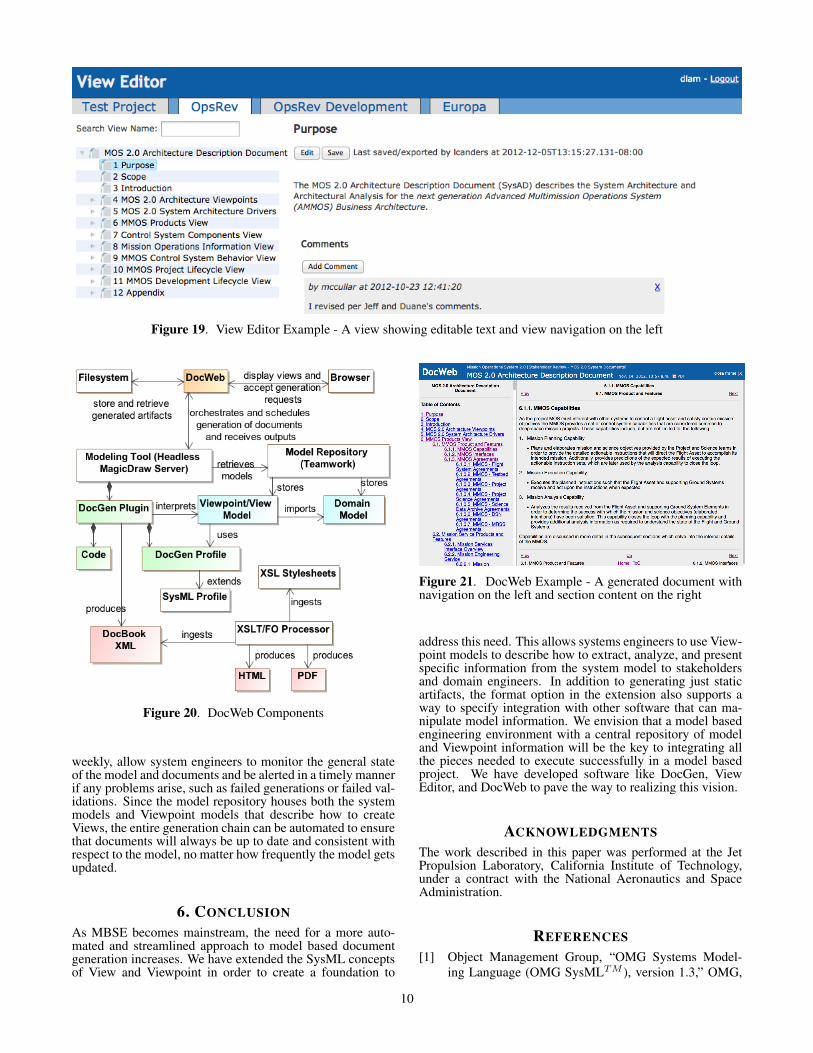
Figure 19. View Editor Example - A view showing editable text and view navigation on the left
Figure 20. DocWeb Components
weekly, allow system engineers to monitor the general stateof the model and documents and be alerted in a timely mannerif any problems arise, such as failed generations or failed val-idations. Since the model repository houses both the systemmodels and Viewpoint models that describe how to createViews, the entire generation chain can be automated to ensurethat documents will always be up to date and consistent withrespect to the model, no matter how frequently the model getsupdated.
6. CONCLUSIONAs MBSE becomes mainstream, the need for a more auto-mated and streamlined approach to model based documentgeneration increases. We have extended the SysML conceptsof View and Viewpoint in order to create a foundation to
Figure 21. DocWeb Example - A generated document withnavigation on the left and section content on the right
address this need. This allows systems engineers to use View-point models to describe how to extract, analyze, and presentspecific information from the system model to stakeholdersand domain engineers. In addition to generating just staticartifacts, the format option in the extension also supports away to specify integration with other software that can ma-nipulate model information. We envision that a model basedengineering environment with a central repository of modeland Viewpoint information will be the key to integrating allthe pieces needed to execute successfully in a model basedproject. We have developed software like DocGen, ViewEditor, and DocWeb to pave the way to realizing this vision.
ACKNOWLEDGMENTSThe work described in this paper was performed at the JetPropulsion Laboratory, California Institute of Technology,under a contract with the National Aeronautics and SpaceAdministration.
REFERENCES[1] Object Management Group, “OMG Systems Model-
ing Language (OMG SysMLTM ), version 1.3,” OMG,
10

Tech. Rep. OMG document number formal/12-06-02,June 2012.
[2] M. Jackson, C. L. Delp, D. Bindschadler, M. Sarrel,R. Wollaeger, and D. Lam, “Dynamic Gate Product andArtifact Generation from System Models,” in Proceed-ings of Aerospace Conference. Big Sky, Montana:IEEE, 2011.
[3] D. Bindschadler, C. L. Delp, and M. McCullar, “Prin-ciples to Products: Toward Realizing MOS 2.0,” inProceedings of SpaceOps Conference. Stockholm,Sweden: AIAA, 2012.
[4] T. Bayer, S. Chung, B. Cole, B. Cooke, F. Dekens,C. Delp, I. Gontijo, and D. Wagner, “Update on theModel Based Systems Engineering on the Europa Mis-sion Concept Study,” in Proceedings of Aerospace Con-ference. Big Sky, Montana: IEEE, 2013.
[5] T. Bayer, M. Bennett, C. L. Delp, D. Dvorak, J. S.Jenkins, and S. Mandutianu, “Update - concept of oper-ations for integrated model-centric engineering at JPL,”in Proceedings of Aerospace Conference. Big Sky,Montana: IEEE, 2011.
[6] DocBook Technical Committee, “DocBook 5,” OASIS,Tech. Rep., 2009, http://docbook.org.
[7] MGSS, “Advanced Multi-Mission Operations System,”http://ammos.jpl.nasa.gov/.
[8] OPFM, “Europa Jupiter System Mission,”https://opfm.jpl.nasa.gov/europajupitersystemmission-ejsm/.
[9] OMG Systems Engineering DSIG, June 2012,http://www.omg.org/news/meetings/tc/ma-12/info.htm.
[10] ISO/IEC/IEEE, “Systems and software engineering -architecture description,” ISO/IEC/IEEE, Tech. Rep.ISO/IEC/IEEE 42010, December 2011.
[11] Europa Study Team, “Europa Study 2012 Report,” Na-tional Aeronautics and Space Administration, May 12012.
[12] S. Chung, T. Bayer, B. Cole, B. Cooke, F. Dekens,C. Delp, and D. Lam, “Model-Based Systems Engi-neering Approach to Managing Mass Margin,” in 5thInternational Workshop on Systems and Concurrent En-gineering for Space Applications. Lisbon, Portugal:ESA, 2012.
[13] NoMagic, “MagicDraw,” http://www.nomagic.com/.
BIOGRAPHY[
Christopher Delp is the Systems Archi-tect for Ops Revitalization task in MGSSand a Lead Systems Engineer for MBSEon the Europa Mission. He is a memberof of the Systems Behavior and Architec-tures Group at the Jet Propulsion Lab-oratory. His interests includes Systemsand Software Architecture, applicationsof Model-Based Systems Engineering ,Model-Based Analysis and Enterprise
Engineering Systems. He earned his M.S. and B.S. degreesfrom the U of A in Systems Engineering.
Doris Lam is currently a SoftwareSystems Architect working in the ModelBased Engineering Environment team atJPL. She earned her B.S. in computerscience from UCLA in 2008 and joinedJPL after graduating. She has workedon various UML and SysML model-ing projects and software modernizationtasks for the ground system.
Elyse Fosse is a Software Systems En-gineer for the Ops Revitalization task inMGSS. She also develops ground systemcost models for deep space and Earthmissions. She is also a member of theMultimission Ground Data System Engi-neering group at the Jet Propulsion Lab-oratory. Her interests include softwareand systems architecture, applicationsof model-based system engineering, and
cost model implementation and analysis. Elyse is also a partof the INCOSE Space Systems Working Group’s entry into theModel Based Systems Engineering Grand Challenge. Elyseearned her M.A. in Applied Mathematics from ClaremontGraduate University and her B.S. in Mathematics from theUniversity of Massachusetts Amherst.
Cin-Young Lee is a Senior SoftwareEngineer in the Mission InformationSystems and Technology DevelopmentGroup at the Jet Propulsion Laboratory.He earned his Ph.D. from Caltech.
11