model ap - csiworldwide.com files/laars mighty therm ap 500-1825... · installation and operation...
TRANSCRIPT
Installation and Operation Instructions Document 3006S
H00
6730
0S
Model APSizes 500 - 1825
These instructions are to be stored in thepocket provided on the heater.
Installation and OperationInstructions for
Mighty ThermPool Heating Boiler
WARNINGIf the information in this manual is notfollowed exactly, a fire or explosion mayresult causing property damage, personalinjury or loss of life.
Do not store or use gasoline or otherflammable vapors and liquids in the vicinityof this or any other appliance.
WHAT TO DO IF YOU SMELL GAS• Do not try to light any appliance.• Do not touch any electrical switch; do not
use any phone in your building.• Immediately call your gas supplier from a
nearby phone. Follow the gas supplier'sinstructions.
• If you cannot reach your gas supplier, callthe fire department.
Installation and service must be performed bya qualified installer, service agency, or gassupplier.
FOR YOUR SAFETY: This product must be installed and serviced by a professional service technician,qualified in hot water boiler installation and maintenance. Improper installation and/or operation couldcreate carbon monoxide gas in flue gases which could cause serious injury, property damage, or death.Improper installation and/or operation will void the warranty.
AVERTISSEMENTAssurez-vous de bien suivres les instructionsdonnées dans cette notice pour réduire auminimum le risque d’incendie ou d’explosion oupour éviter tout dommage matériel, touteblessure ou la mort.
Ne pas entreposer ni utiliser d’essence nid’autres vapeurs ou liquides inflammables dansle voisinage de cet appareil ou de tout autreappareil.QUE FAIRE SI VOUS SENTEZ UNE ODEUR DE GAZ:
• Ne pas tenter d’allumer d’appareils.• Ne touchez à aucun interrupteur. Ne pas vous
servir des téléphones dansle bâtiment où vousvous trouvez.
• Appelez immédiatement votre fournisseur degaz depuis un voisin. Suivez les instructionsdu fournisseur.
• Si vous ne pouvez rejoindre le fournisseur degaz, appelez le sservice des incendies.
L’installation et l’entretien doivent être assurés parun installateur ou un service d’entretien qualifié oupar le fournisseur de gaz.
LAARS HEATING SYSTEMSPage 2
TABLE OF CONTENTS
SECTION 1.General Information1.1 Introduction ................................................... 31.2 Heater Identification ..................................... 31.3 Primary/Secondary Pump and Piping ........... 31.4 Certifications ................................................. 31.5 Engineering Assistance ................................ 3
SECTION 2.Installation2.1 Boiler Placement .......................................... 42.2 Installation of Indoor Boilers ......................... 42.2.1 Combustion Air Supply ................................. 42.2.2 Venting ......................................................... 52.2.3 Common Venting System
Test Procedure ............................................. 62.2.3 Instructions Relatives au Test des
Systèmes à Évent Commun ......................... 62.3 Installation of Outdoor Boilers ...................... 72.4 Gas Supply and Piping ................................. 72.5 Electrical Wiring ............................................ 82.6 General Piping Instructions .......................... 92.7 Boiler By-Pass Piping ................................... 92.8 Temperature Sensor Placement
and Installation ............................................ 102.9 Automatic Chlorinators ............................... 10
SECTION 3.Operation3.1 Controls - General ...................................... 113.2 Initial Start-Up ............................................. 123.3 Safety Shutoff Component Checkout ......... 123.4 Inlet Temperature and
Temperature Rise Adjustment .................... 133.5 Heater Shut Down ...................................... 133.6 Spring and Fall Operation
Stand-by Service ........................................ 133.7 Winter Operation Complete Shutdown ....... 143.8 Time Clock Operation ................................. 143.9 Therapeutic Pools (Spas) ........................... 14
SECTION 4.Maintenance ..............................................15
SECTION 5.Troubleshooting .......................................16
SECTION 6.Parts Description and Order Numbers ....... 18

Mighty Therm Commercial Pool Heating Boiler Page 3
SECTION 1.General Information1.1 Introduction
This manual provides information for theinstallation and operation of Laars Model AP poolheating boilers. It is strongly recommended that allapplication and installation procedures be reviewedcompletely before proceeding with the installation.Consult the Laars factory, or local factoryrepresentative, with any problems or questionsregarding this equipment. Experience has shown thatmost problems are caused by improper installation, notsystem design.
Some accessory items are shipped in separatepackages. Verify receipt of all packages listed on thepacking slip. Inspect everything for possible damageupon delivery, and inform the carrier of any shortagesor impairments. Any such claims should be filed withthe carrier. The carrier, not the shipper, is responsiblefor shortages and damage to the shipment whethervisible or concealed.
The warranty does not apply to heaters notinstalled or operated in accordance with theseprocedures. Consult local building and safety codesbefore proceeding with work. The installation mustconform to the requirements of the authority havingjurisdiction or, in the absence of such requirements, tothe latest edition of the National Fuel Gas Code; ANSIZ223.1, National Electrical Code ANSI/NFPA 70. InCanada, the installation must conform with the latestedition of CAN/CGA-B149 requirements.
When required by the authority havingjurisdiction, the installation must conform to
Figure 1. Heater Identification (model nomenclature).
WARNINGThe model AP commercial pool heating boilermust be used on potable water only. Forheating pools containing salt water, a speciallyequipped heater must be used; consult yourdistributor or factory representative. The poolheating boiler must be installed in accordancewith the procedures outlined in this manual.
MODEL
AP-POOL
REVISION
P-PUMP (U.S.)Q-PUMP (CAN)
HEAT EXCHANGER
C-GLASS LINED/COPPERN-GLASS LINES/CU-NIK-BRONZE/COPPERS-BRONZE/CU-NI
VERSION
1 - 8 TUBEB-10 TUBE
I-INDOOR
E-OUTDOOR
FUEL
N-NATURALP-PROPANE
IGNITION
04-SPARK 110V09-SPARK 24V
11-SPARK 24V
16-STND. PILOT
SIZE
BTU/HR X 10000500060007150850099910101200143016701825
C
FIRING MODE
ON/OFF
1 2 3 4 5 6 7 8 9 10 11 12 13 14
American Society of Mechanical Engineers safetycodes for controls and safety devices for automaticallyfired heaters No. CSD-1, and in Canada CGA 3.3.Any modification of the heater, its gas controls, gasorifices, wiring or drafter diverter may void the Laarswarranty. If field conditions require suchmodifications, consult factory.
1.2 Heater IdentificationConsult rating plate on the heating boiler. Shown
below is a breakdown of the model nomenclature.Laars commercial pool heating boilers are available intwo configurations: an indoor version and an outdoorversion. Outdoor models are not available in Canada.
1.3 Primary/Secondary Pump and PipingAll models are supplied with integrally mounted
pumps. The 1825 models use a 3/4 HP pump and allother models are supplied with 1/2 HP pumps. Thesepumps are sized for the pressure drop through the heatexchanger and through the bypass piping as shown inFigure 10.
Any deviations from the arrangement shown mayincrease the head on the pump, reduce flow and hinderperformance (see Section 2.7). For spas see Section3.9.
This piping arrangement and the integral pumpallow hot water to be recirculated to the heater inlet,thus raising the inlet temperature and greatly reducingcondensation.
1.4 CertificationsAll models are design-certified by AGA and
CGA for natural or propane gas and conform toASME Code requirement for 160 PSI water pressure.
1.5 Engineering AssistanceConsult the factory or distributor regarding any
questions or problems which arise in the specification,installation or operation of Laars equipment. Anexperienced engineering staff is ready to assist inassuring the proper performance and application ofLaars products.

LAARS HEATING SYSTEMSPage 4
SECTION 2.Installation2.1 Boiler Placement
The pool heating boiler must be placed toprovide specific clearances on all sides formaintenance and inspections. There must also beminimum distances maintained from combustiblesurfaces. These clearances also apply tononcombustible materials because the pool heatingboiler requires air circulation for proper operation.
The pool heating boiler should be mounted on alevel surface. An integral base for an installation oncombustible flooring is provided as standardequipment on outdoor models. For indoor models,special base rails part number 10539000 must be usedfor combustible flooring.
Do not install a pool heating boiler on carpeting.Under the national Fuel Gas Code, ANSI
Z223.1, it is permissible to place the boiler on floorsother than noncombustible when the installationcomplies with the American Insurance Code. Figures2, 3, 4 and 5 show common installation oncombustible flooring.
2.2 Installation of Indoor BoilersLocate the pool heating boiler to provide
adequate clearance for inspection and service on allsides. See Table 1. For alcove installation, seeFigure 6.
Install indoor heaters on a waterproof floor withan adequate floor drain and a 6" (152mm) minimumcurb on all four sides to protect the building if heaterrepairs are required. The manufacturer will not beheld liable for any water damage in connectionwith this boiler.
2.2.1 Combustion Air SupplyThe heater location must provide sufficient air
supply for proper combustion and ventilation of thesurrounding area as outlined in the latest edition ofANSI standard Z223.1, and any local codes that maybe applicable. Inadequate combustion air supply mayresult in incomplete combustion, sooting of the heatexchanger, and unsafe operation of the boiler.
a. Conventional VentilationIn the United States, these requirements specify
that small boiler rooms should be provided with twopermanent air supply openings communicatingdirectly through the wall to outside air one within 12inches (305mm) of the ceiling, and the other within12 inches (305mm) of the floor. Each opening shouldhave a minimum free area of one square inch(6.5 sq. cm) per 4,000 BTU/hr input of the total inputrating of all appliances in the enclosed area. See Table2 for recommended air supply for each model. Animproperly ventilated equipment room can get
Clearance Indoor Outdoorfrom in. mm in. mm
Top 30 762 unobstructed
Water Conn. side 12* 305 24 610
Pump side 6* 152 24 610
Front Alcove* unobstructed
Rear 8 203 24 610
Vent pipe** 6 152 - - -
Hot water pipes per code per code
* Water connection and pump side clearances of 24" (610mm)and front clearances of 48" (1219mm) will allow easierservice access.
** Using type B vent (refer to Manufacturer's Instructions).
Table 1. Minimum boiler clearances fromadjacent surfaces.
Figure 2. Typical Boiler Installation on Concrete Slab.
Figure 3. Typical Boiler Installation on Roof UsingRaised Platform (wood).
excessively hot and cause accelerated deteriorationof controls and electrical components.
In Canada, Table 2 does not apply. Consult localbuilding codes or, in the absence of suchrequirements, follow CGA requirements and/or CAN/CGA B-149 standard.
Mighty Therm Commercial Pool Heating Boiler Page 5
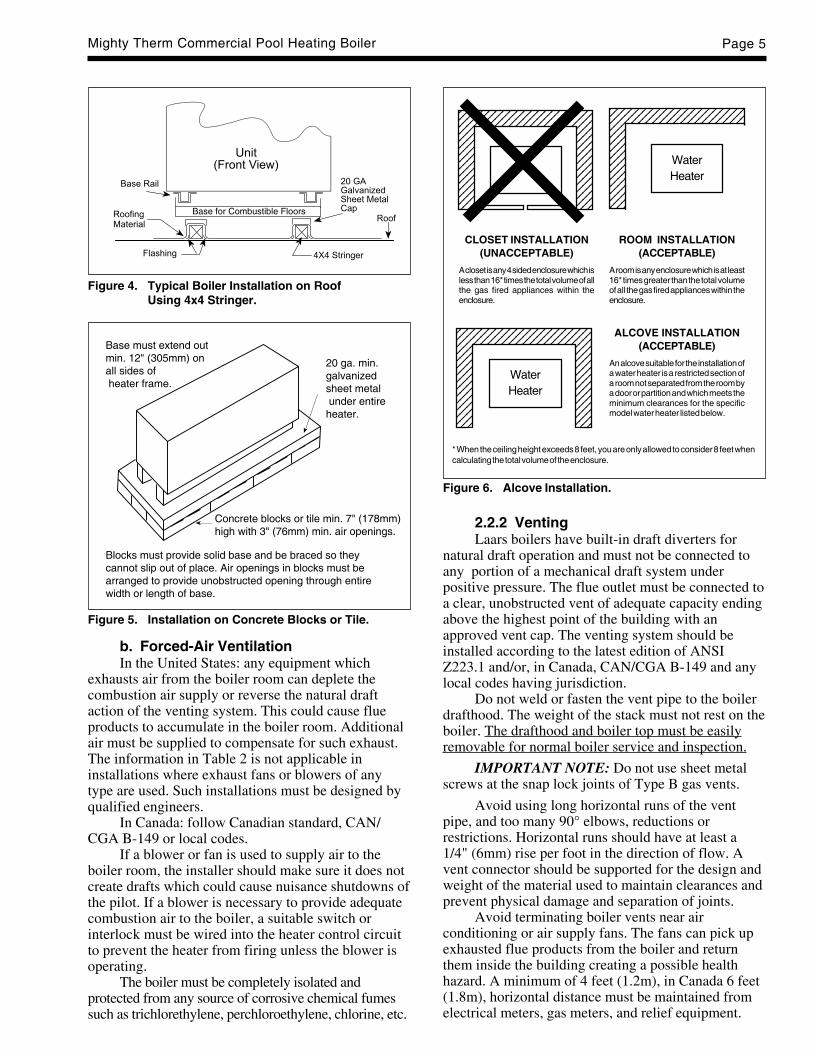
Figure 4. Typical Boiler Installation on RoofUsing 4x4 Stringer.
Figure 5. Installation on Concrete Blocks or Tile.
b. Forced-Air VentilationIn the United States: any equipment which
exhausts air from the boiler room can deplete thecombustion air supply or reverse the natural draftaction of the venting system. This could cause flueproducts to accumulate in the boiler room. Additionalair must be supplied to compensate for such exhaust.The information in Table 2 is not applicable ininstallations where exhaust fans or blowers of anytype are used. Such installations must be designed byqualified engineers.
In Canada: follow Canadian standard, CAN/CGA B-149 or local codes.
If a blower or fan is used to supply air to theboiler room, the installer should make sure it does notcreate drafts which could cause nuisance shutdowns ofthe pilot. If a blower is necessary to provide adequatecombustion air to the boiler, a suitable switch orinterlock must be wired into the heater control circuitto prevent the heater from firing unless the blower isoperating.
The boiler must be completely isolated andprotected from any source of corrosive chemical fumessuch as trichlorethylene, perchloroethylene, chlorine, etc.
2.2.2 VentingLaars boilers have built-in draft diverters for
natural draft operation and must not be connected toany portion of a mechanical draft system underpositive pressure. The flue outlet must be connected toa clear, unobstructed vent of adequate capacity endingabove the highest point of the building with anapproved vent cap. The venting system should beinstalled according to the latest edition of ANSIZ223.1 and/or, in Canada, CAN/CGA B-149 and anylocal codes having jurisdiction.
Do not weld or fasten the vent pipe to the boilerdrafthood. The weight of the stack must not rest on theboiler. The drafthood and boiler top must be easilyremovable for normal boiler service and inspection.
IMPORTANT NOTE: Do not use sheet metalscrews at the snap lock joints of Type B gas vents.
Avoid using long horizontal runs of the ventpipe, and too many 90° elbows, reductions orrestrictions. Horizontal runs should have at least a1/4" (6mm) rise per foot in the direction of flow. Avent connector should be supported for the design andweight of the material used to maintain clearances andprevent physical damage and separation of joints.
Avoid terminating boiler vents near airconditioning or air supply fans. The fans can pick upexhausted flue products from the boiler and returnthem inside the building creating a possible healthhazard. A minimum of 4 feet (1.2m), in Canada 6 feet(1.8m), horizontal distance must be maintained fromelectrical meters, gas meters, and relief equipment.
Figure 6. Alcove Installation.
Base must extend outmin. 12" (305mm) onall sides of heater frame.
20 ga. min.galvanizedsheet metal under entireheater.
Concrete blocks or tile min. 7" (178mm)high with 3" (76mm) min. air openings.
Blocks must provide solid base and be braced so theycannot slip out of place. Air openings in blocks must bearranged to provide unobstructed opening through entirewidth or length of base.
* When the ceiling height exceeds 8 feet, you are only allowed to consider 8 feet whencalculating the total volume of the enclosure.
123456789012345678901234567890123456789012345678901234567890123456789012345678901234567890123456789012345678901234567890123456789012345678901234567890123456789012345678901234567890123456789012345678901234567890123456789012345678901234567890123456789012345678901234567890123456789012345678901234567890
WaterHeater
123456789012345678901234567890123456789012345678901234567890123456789012345678901234567890123456789012345678901234567890123456789012345678901234567890123456789012345678901234567890123456789012345678901234567890123456789012345678901234567890123456789012345678901234567890123456789012345678901234567890
CLOSET INSTALLATION(UNACCEPTABLE)
A closet is any 4 sided enclosure which isless than 16* times the total volume of allthe gas fired appliances within theenclosure.
ROOM INSTALLATION(ACCEPTABLE)
A room is any enclosure which is at least16* times greater than the total volumeof all the gas fired appliances within theenclosure.
123456789012345678901234567890123456789012345678901234567890123456789012345678901234567890123456789012345678901234567890123456789012345678901234567890123456789012345678901234567890123456789012345678901234567890123456789012345678901234567890123456789012345678901234567890123456789012345678901234567890
WaterHeater
ALCOVE INSTALLATION(ACCEPTABLE)
An alcove suitable for the installation ofa water heater is a restricted section ofa room not separated from the room bya door or partition and which meets theminimum clearances for the specificmodel water heater listed below.

LAARS HEATING SYSTEMSPage 6
Always use double-wall or insulated vent pipe(Type B or equivalent). In cold weather, uninsulatedoutside vents can chill the rising flue productsblocking the natural draft action of the ventingsystems. This can create a health hazard by spillingflue products in the boiler room.
Avoid oversized vent piping or extremely longruns of pipe which may cause excessive cooling andcondensation. Rule of Thumb: the total length of thevent, including the connector and any offset, shouldnot exceed 15 feet (4.6m) for every inch (25mm) ofvent diameter. Longer total lengths shown in ventingtables are based on maximum capacity, notcondensation factors.
When the installation of a draft fan is necessaryin connecting a venting system to a Laars boiler, theinstallation should be engineered by competentpersonnel following good engineering practices. Thedraft fan supplier should be consulted for correct size.The installation should be in accordance with thelatest edition of ANSI Z223.1 and/or, in Canada,CAN/CGA B-149 and any local codes havingjurisdiction. When a draft fan is installed, a suitabledraft switch must be wired into the boiler controlcircuit at terminal designated "Field Interlock" toprevent firing of the boiler unless a positive draft hasbeen established.
2.2.3 Common Venting SystemTest ProcedureAt the time of the removal of an existing heater,
the following steps shall be followed with eachappliance remaining connected to the common ventingsystem. During the testing of each unit, the otherappliances remaining connected to the commonventing system should not be operated.1. Seal any unused openings in the common
venting system.2. Visually inspect the venting system for proper
size and horizontal pitch. Determine that there isno blockage or restriction, leakage, corrosion, orother deficiencies which could cause an unsafecondition.
3. Insofar as it is practical, close all building doorsand windows. Also close all doors between thespace in which the appliances remainingconnected to the common venting system arelocated and the other spaces of the building. Turnon any clothes dryer and any appliance notconnected to the common venting system. Turnon any exhaust fans, including range hoods andbathroom exhausts, so they will operate atmaximum speed. Do not operate a summerexhaust fan. Close all fireplace dampers.
4. Place in operation the appliance being inspected.Follow the lighting instructions for the unit.Adjust the thermostat so the appliance willoperate continuously.
5. Test for spillage at the draft hood relief openingafter 5 minutes of main burner operation. Use theflame of a match or candle, or smoke from acigarette, cigar, or pipe.
6. After it has been determined that each applianceremaining connected to the common ventingsystem properly vents when tested as outlinedabove, return doors, windows, exhaust fans,fireplace dampers and any other gas-burningappliance to their previous condition of use.
7. Any improper operation of the common ventingsystem should be corrected so the installationconforms with the National Fuel Gas Code,ANSI Z223.1 and/or CAN/CGA B149,Installation Codes. When resizing any portion ofthe common venting system, the commonventing system should be resized to approach theminimum size as determined using theappropriate tables in Appendix G in the NationalFuel Gas Code, ANSI Z223.1 and/or CAN/CGAB149 Installation Codes.
2.2.3 Instructions Relatives au Test des Systèmesà Évent CommunAu moment du restrait d’une chaudière existante,
les mesures suivantes doivent être prises pour chaqueappareil toujours reccordé au système d’évacuation nefonctionnet pas:1. Sceller toutes les ouvertures non utilisées du
systèmes d’évacuation.2. Inspecter de façon visuelle le système
d’évacuation pour déterminer la grosseur etl’inclinaison horizontale qui conviennent ets’assurer que le système est exemptd’obstruction, d’étranglement, de fuite, decorrosion et autres défaillances qui pourraientprésenter des risques.
3. Dans la mesure du possible, fermer toutes lesportes et les fenêtres du bâtiment et toutes lesportes entre l’espace où les appareils toujoursraccordés au système d’évacuation sont installéset les autres espaces du bâtiment. Mettre enmarche les sécheuses, tous les appareils nonraccordés au système d’évacuation common ettous les ventilateurs d’extraction comme leshottes de cuisinière et les ventilateurs des sallesde bain. S’assurer que ces ventilateursfonctionnent à la vitesse maximale. Ne pas fairefonctionner les ventilateurs d’été. Fermer lesregistres des cheminées.
4. Mettre l’appareil inspecté en marche. Suivre lesinstructions d’allumage. Régler le thermostat defaçon que l’appareil fonctionne de façoncontinue.
5. Faire fonctionner le brûleur principal pendant 5min ensuite, déterminer si le coupe-tiragedéborde à louverture de décharge. Utiliser la

Mighty Therm Commercial Pool Heating Boiler Page 7
flamme d’une chandelle ou la fumée d’unecigarette, d’une cigare ou d’une pipe.
6. Une fois qu’il a été déterminé, selon la méthodeindiquée ci-dessus, que chaque appareil raccordéau systéme d’évacuation est mis à l’air libre defaçon adéquate. Remettre les portes et lesfenêtres, les ventilateurs, les registres decheminées et les appareils au gaz à leur positionoriginale.
7. Tout mauvais fonctionnement du systémed’évacuation commun devrait être corrigé defaçon que l’installation soit conforme auNational Fuel Gas Code, ANSI.Z223.1 et (ou)aux codes d’installation CAN/CGA-B149. Si lagrosseur d’une section du système d’évacuationdoit être modifiée, le système devrait êtremodifié pour respecter les valeurs minimales destableaux pertinents de l’appendice G du NationalFuel Gas Code, ANSI Z2231.1 et (ou) des codesd’installation CAN/CGA-B149.
2.3 Installation of Outdoor Boilers(Not available in Canada)
1. Locate the boiler to provide the clearances aslisted in Table 1, “Minimum Boiler Clearances.”
2. Do not place the boiler in an enclosure or wallrecess. Avoid locations where wind deflectionoff structures might cause downdraft. When suchwind conditions are possible, place the heater atleast 3 feet (0.9m) from the structures.
3. Never install the boiler under any kind of roofoverhang. Do not place the boiler below oradjacent to any doors, windows, louvers, grills,etc., which connect in any way with an inhabitedarea of a building. This includes other structuressuch as garages or utility rooms (see Figure 7).
4. Although these models are CSA designedcertified for outdoor installations, suchinstallations are not recommended in areas wherethe danger of freezing exists unless properprecautions are taken for freeze protection.
Outdoor installations are not recommended inareas where the danger of snow blockage exists.
WARNINGLiquefied petroleum gas is heavier than air.Therefore, the pool heating boiler should not beinstalled in pits or other locations where gascould accumulate.
The boiler should be located a safe distance fromPropane gas storage and filling equipment. Consultlocal codes and fire protection authorities for adviceon specific installation restrictions.
2.4 Gas Supply and PipingReview the following instructions before
proceeding with the installation.1. Verify that the boiler is fitted for the proper type
of gas by checking the rating plate. Laars boilersare normally equipped to operate below a2000 foot (609.6m) altitude. Boilers equipped tooperate at higher altitudes have appropriatestickers or tags attached, also printed informationon rating plate.
2. Use the figures in Table 3 to provide adequategas piping from the gas meter to the boiler.
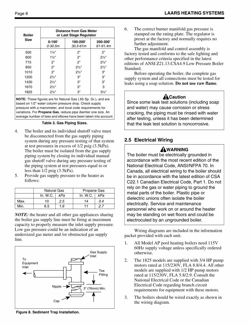
3. A sediment trap (drip leg) must be providedahead of the gas controls (see Figure 8). Amanual gas shutoff valve must also be providedfor service convenience and safety. Check thelocal codes.
Boiler Each Opening*Size square inches square cm
500 125 806.5600 150 967.8
715 179 1154.9
850 213 1374.3
1010 253 1632.4
1200 300 1935.6
1430 358 2309.8
1670 418 2696.9
1825 457 2948.6
* Net Free Area.
Check with louver manufacturers for net free area of louvers.Correct for screen resistance to the net free area if a screen isinstalled. Check all local codes applicable to combustion air.
Area indicated is for one of two openings: one at floor leveland one at the ceiling, so the total net free area could bedouble the figures indicated. For special conditions refer to thelatest editon of ANSI Z223.1.
Consult factory if openings do not communicate directlythrough the walls with the outdoors.
Table 2. Minimum Recommended Air Supply to Boiler.
Figure 7. Incorrect Outdoor Installation.
LAARS HEATING SYSTEMSPage 8
6. The correct burner manifold gas pressure isstamped on the rating plate. The regulator ispreset at the factory and normally requires nofurther adjustment.The gas manifold and control assembly is
factory tested and conforms to the safe lighting andother performance criteria specified in the latesteditions of ANSI Z21.13.CSA4.9 Low Pressure BoilerStandard.
Before operating the boiler, the complete gassupply system and all connections must be tested forleaks using a soap solution. Do not use raw flame.
CautionSince some leak test solutions (including soapand water) may cause corrosion or stresscracking, the piping must be rinsed with waterafter testing, unless it has been determinedthat the leak test solution is noncorrosive.
2.5 Electrical Wiring
WARNINGThe boiler must be electrically grounded inaccordance with the most recent edition of theNational Electrical Code, ANSI/NFPA 70. InCanada, all electrical wiring to the boiler shouldbe in accordance with the latest edition of CSAC22.1 Canadian Electrical Code, Part 1. Do notrely on the gas or water piping to ground themetal parts of the boiler. Plastic pipe ordielectric unions often isolate the boilerelectrically. Service and maintenancepersonnel who work on or around the heatermay be standing on wet floors and could beelectrocuted by an ungrounded boiler.
Wiring diagrams are included in the informationpacket provided with each unit.
1. All Model AP pool heating boilers need 115V60Hz supply voltage unless specifically orderedotherwise.
2. The 1825 models are supplied with 3/4 HP pumpmotors rated at 115/230V, FLA 8.8/4.4. All othermodels are supplied with 1/2 HP pump motorsrated at 115/230V, FLA 5.8/2.9. Consult theNational Electrical Code or the CanadianElectrical Code regarding branch circuitrequirements for equipment with these motors.
3. The boilers should be wired exactly as shown inthe wiring diagram.
Distance from Gas MeterBoiler or Last Stage RegulatorSize 0-100' 100-200' 200-300'
0-30.5m 30.5-61m 61-91.4m
500 1½" 2" 2"600 1½" 2" 2½"715 2" 2" 2½"850 2" 2½" 2½"
1010 2" 2½" 3"1200 2½" 3" 3"1430 2½" 3" 3"1670 2½" 3" 3
1825 2½" 3" 3½"
NOTE: These figures are for Natural Gas (.65 Sp. Gr.), and arebased on 1/2" water column pressure drop. Check supplypressure with a manometer, and local code requirements forvariations. For Propane Gas, reduce pipe diamter one size. Anaverage number of tees and elbows have been taken into account.
Table 3. Gas Piping Sizes.
Figure 8. Sediment Trap Installation.
ToEquipmentInlet
Gas SupplyInlet
TeeFitting
3" (76mm) Min.
Cap
Nipple
4. The boiler and its individual shutoff valve mustbe disconnected from the gas supply pipingsystem during any pressure testing of that systemat test pressures in excess of 1/2 psig (3.5kPa).The boiler must be isolated from the gas supplypiping system by closing its individual manualgas shutoff valve during any pressure testing ofthe piping system at test pressures equal to orless than 1/2 psig (3.5kPa).
5. Provide gas supply pressure to the heater asfollows:
Natural Gas Propane GasIn. W.C. kPa In. W.C. kPa
Max. 10 2.5 14 3.4Min. 6.5 1.6 11 2.7
NOTE: the heater and all other gas appliances sharingthe boiler gas supply line must be firing at maximumcapacity to properly measure the inlet supply pressure.Low gas pressure could be an indication of anundersized gas meter and /or obstructed gas supplyline.
Mighty Therm Commercial Pool Heating Boiler Page 9
IMPORTANT NOTE: The pool filter pump andboiler must be electrically interlocked so the boilercannot come on unless the pump is running and thereis full flow in the filter piping where the boiler isconnected. If the pool filter pump operation isintermittent the boiler must be shut off prior to pumpshutdown. See paragraph heading Auxiliary TimeClock Wiring below. If the backwash operation ismanual the boiler must be shut off manually duringbackwashing.
Auxiliary Time Clock Wiring:If a time clock is used to control the filter pump
operation, a separate switch or relay must be used toshut off the boiler at least 15 minutes before the filterpump is shut off. Wire the switch or relay (often calledthe Fireman Switch) to the terminals shown in thewiring diagram as “Field Interlock.”
4. All field installed electrical safety devices and allfield installed controllers (valve end switches,draft switches, relays, timers) can be connectedto the boiler control to the terminals shown in thewiring diagram designated “Field Interlock.”
5. Field location of the temperature sensor isdescribed in Section 2.8.
Where the boiler is installed with a draft fan referto the fan manufacturer's wiring diagram. The draftswitch should be wired across the field interlockterminals in the boiler control panel.
2.6 General Piping InstructionsIn addition to the bypass valve “B” and outlet
valve “A” shown in Figures 10 and 11, an inlet valve“C” should be provided so that the heater can bereadily isolated for service. All valves should bebutterfly or ball style, not gate valves. For spasapplication see Section 3.9.
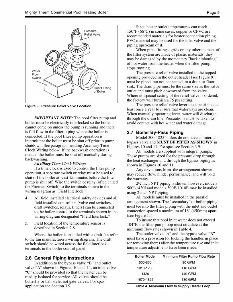
Figure 9. Pressure Relief Valve Location.
Since heater outlet temperatures can reach150°F (66°C) in some cases, copper or CPVC arerecommended materials for heater connection piping.PVC material may be used for the inlet valve and thepiping upstream of it.
When pipe, fittings, grids or any other element ofthe filter system are made of plastic materials, theymay be damaged by the momentary "back siphoning"of hot water from the heater when the filter pumpstops running.
The pressure relief valve installed in the tappedopening provided in the outlet header (see Figure 9),must be piped, but not connected, to a drain or floorsink. The drain pipe must be the same size as the valveoutlet and must pitch downward from the valve.Where no special setting of the relief valve is ordered,the factory will furnish a 75 psi setting.
The pressure relief valve lever must be tripped atleast once a year to insure that waterways are clean.When manually operating lever, water will dischargethrough the drain line. Precautions must be taken toavoid contact with hot water and water damage.
2.7 Boiler By-Pass PipingModel 500-1825 boilers do not have an internal
bypass valve and MUST BE PIPED AS SHOWN inFigures 10 and 11. For spas see Section 3.9.
All models are supplied with integral pumps,These pumps are sized for the pressure drop throughthe heat exchanger and through the bypass piping asshown in Figures 10 and 11.
Any deviations from the arrangement shownmay reduce flow, hinder performance, and will voidthe warranty.
2½ inch NPT piping is shown, however, models500I-1430I and models 500E-1010E may be installedusing 2 inch NPT piping.
All models must be installed in the parallelarrangement shown. The "secondary" or boiler pipingmust tee into the filter piping with the inlet and outletconnection spaced a maximum of 18" (450mm) apart(see Figure 11).
To insure that pool inlet water does not exceed104°F, the filter pump loop must circulate at theminimum flow rates shown in Table 4.
The outlet valve “A” and the bypass valve “B”must have a provision for locking the handles in place(or removing them) after the temperature rise and inlettemperature adjustments have been made.
Boiler Model Minimum Filter Pump Flow Rate
500-850 90 GPM
1010-1200 110 GPM
1430 140 GPM
1670-1825 180 GPM
Table 4. Minimum Flow to Supply Heater Loop.

LAARS HEATING SYSTEMSPage 10
Figure 10. Boiler By-Pass Piping.
2.8 Temperature Sensor Placementand InstallationA temperature sensor with 15 feet (5m) of cable
and an immersion well assembly are supplied with theboiler. These must be installed in the field. Refer toFigures 10 through 12.
1. The immersion well body is provided with a 1/2"NPT. Mount the immersion well on theunderside of the filter circulation piping, justupstream of the boiler inlet tee as close to theboiler as possible (see Figure 11). DO NOTINSTALL in secondary piping or downstreamof the boiler inlet tee.
2. Thread the spring and retainer onto the sensorcable and secure sensor into the immersion well.
3. Route cable to heater control panel in a locationwhere it will not be subject to damage. Securewith nylon cable ties.
2.9 Automatic ChlorinatorsA concentration of chlorine in the heater can be
very destructive, therefor the following rules about theinstallation and operation of such devices must befollowed:
1. The chlorinator should be installed so itintroduces the gas or solution downstream fromthe boiler.
Figure 11. Heater Piping Arrangement.
Suggested By-Pass Loop Fitting
Item Description Material
1 2½" Elbow (See Note) 2½" S-80
2 2½" x 2" ReducingBushing (See Note) CPVC
3 2½" Tee (All Sizes) Copper isoptional
4 2½" Tee (See Note)
A, B,C, D
2½" Ball Valve (See Note)
Note: 2" pipe, fittings and valves are optional for indoor size(500 through 1430) and outdoor size (500 through 1010).

Mighty Therm Commercial Pool Heating Boiler Page 11
Figure 12. Controls Location.
Rating Plate
ManualPilotValve
WaterCirculatingPump
SafetyGasValve
Operating/SafetyGas Valve
Ignition Control
FlowSwitch
PressureReliefValve
Power(On/Off/Auto)Switch
Pump TimeDelay Relay
OperatingControl
Terminal Strip
In
Out
Hi-Limit
ManualMainGas Valve
2. The chlorinator should be wired so it cannotoperate unless the filter pump is running.
3. The chlorinator should be provided with an anti-siphon device so that the draining of the pipingafter the pump shuts off will not siphon chlorinesolution into the boiler.
4. When the operation of a chlorinator is such thatit must be installed in the pump suction, or someother place where the chlorine solution flowsthrough the heater, corrosion of the heater canoccur. Excessive concentrations of chlorinecaused by improper adjustment or failure of thechlorination equipment cause this corrosion. Theresulting damage to the heat exchanger is notcovered by heater warranty.
SECTION 3.Operation3.1 Controls - General
(see Figures 12 and 13)1. Electronic Ignition Controls:
a. Intermittent Ignition:
Pilots are automatically lit when theoperating control calls for heat (Systems #4and #9). The unit performs its own safetycheck and opens the main valves only afterthe pilot is proven to be lit. Whenever the
pilot flame is interrupted, the main gasvalve closes within 0.8 seconds.
b. Electronically Supervised Standing PilotSystem (System #16):
When pilot flame fails, the ignition controlmodule responds in less than 0.8 secondsand provides 100% safety shutdown.
2. Operating Controls:An electronic temperature control is provided onmodel AP boilers to control the pool watertemperature. The temperature sensor (thermistor)is located in the filter circulation piping (seeSection 2.8).
3. Boiler Power (On/Off/Auto) Switch:This provides for constant or automatic pumpoperation.
4. High Limit Controls:The manual reset high limit switch is provided asstandard equipment on all boilers. Thetemperature sensing bulb of the switch is alwayslocated in the heater outlet. Burners willautomatically shut down whenever overheatingof water occurs.
5. Flow Switch:Standard on all AP pool heating boilers. Theswitch is mounted in a tee fitting on the outletheader. This is a paddle type switch which isdeflected by the water flow in the fitting. Anycondition which interrupts or decreases the flow

LAARS HEATING SYSTEMSPage 12
through the secondary loop will shut down theburners.
6. Low Water Cut Off (optional):The low water cut off automatically shuts offboiler whenever water level in the heatexchanger drops below probe level. It is locatedin the inlet header.
3.2 Initial Start-Up
WARNING
Do not use this appliance if any part has beenunder water. Immediately call a qualifiedservice technician to inspect the heater. thepossible damage to a flooded appliance can beextensive and present numerous safetyhazards. Any appliance that has been underwater must be replaced.
On a newly constructed pool, be sure to run thefilter pump long enough for a complete “turn-over” ofthe pool water before starting heater so that dirt andresidue from construction will have been removed.The filter may clog rapidly during this period, causingsevere cycling of the heater.
1. Before placing the heater in operation, be certainthat the heater is filled with water and that all airis purged from the system. Open all the valves inthe secondary piping.
2. With the filter pump running, run the heaterpump in manual “CONSTANT PUMP” forminimum of 10 minutes and listen for the flowswitch to make as the pump is started. Loosenthe pipe plug on the top of the pump scrollcasting to bleed off any air. NOTE: If the systemwill be operated in a manner that causes air to bedrawn into the heater and the secondary piping,an automatic float type air vent should bepermanently installed on top of the pump scroll.
3. To check the heater firing, proceed as follows:
a. Turn off the power switch.
b. Turn off all manual gas valves and waitfive minutes (Figure 14).
c. Set operating control to the lowest setting.
d. After placing the manual pilot gas valve inthe open position and resetting all safetydevices (high limit, low water cutoff, etc.),the pilot(s) can be lit following theprocedure on the heater rating plate.
e. For standing pilot system, press on pilotrelay knob (see Figure 16), light pilot andkeep relay knob depressed for one minute
then release. Once the pilot is lit, turnpower switch to “AUTO PUMP.”
f. Wait 5 minutes and turn up operatingcontrol until heater fires (for intermittentignition system, the pilot will be ignitedautomatically). The main burners shouldignite smoothly. Turn the operating controlback to the lowest setting.
NOTE: DO NOT OPERATE HEATER UNTILTHE FOLLOWING SAFETY CHECKS HAVEBEEN PERFORMED.
3.3 Safety Shutoff Component Checkout1. Once the pilot(s) is lit and has been established
for five minutes, the flame failure response timeshould be checked as follows:
Systems 4 and 9 - (intermittent ignition). With thissystem pilots are automatically lit when the operatingcontrols call for heat. If the pilot flame fails for anyreason, the main valve is shut off within one secondand the pilot spark ignition is initiated until the pilotflame has been reestablished. This sequence should bechecked by turning off the manual pilot gas valve (seeFigure 15), and, at the same time, monitoring theaudible sparking at the pilot burner and signalinterruption to the main valve.
CautionPropane gas is heavier than air and sinks tothe ground. Exercise extreme care in lightingthe heater when so equipped.
System 16 - (electronically supervised standing pilotsystem). Extinguish the pilot flame by placing themanual pilot valve in the closed positions (seeFigure 15), and at the same time, begin recording thetime it takes for the output signal from the electronicignition control to be interrupted. The signalinterruption can be detected either with a test light or avoltmeter. The response time should never exceed onesecond.2. Hi-Limit Checkout. For spas see Section 3.9. The
manual reset high limit is factory preset to 150°F(66°C). Confirm this set point on the unit andadjust if necessary. After running the heater in afiring mode for 10 minutes, slowly close theoutlet valve “A” to raise the outlet temperature asindicated on the outlet thermometer. The highlimit should trip within 2°F (1°C) or 3°F (2°C) ofthe 150°F (66°C) setpoint and shut off theburners. If this does not occur, adjust the setpoint on the unit to shut off the burners when theoutlet thermometer reads 150°F (66°C). Open theoutlet valve “A” and push the reset button. Themain burners should reignite.
Mighty Therm Commercial Pool Heating Boiler Page 13
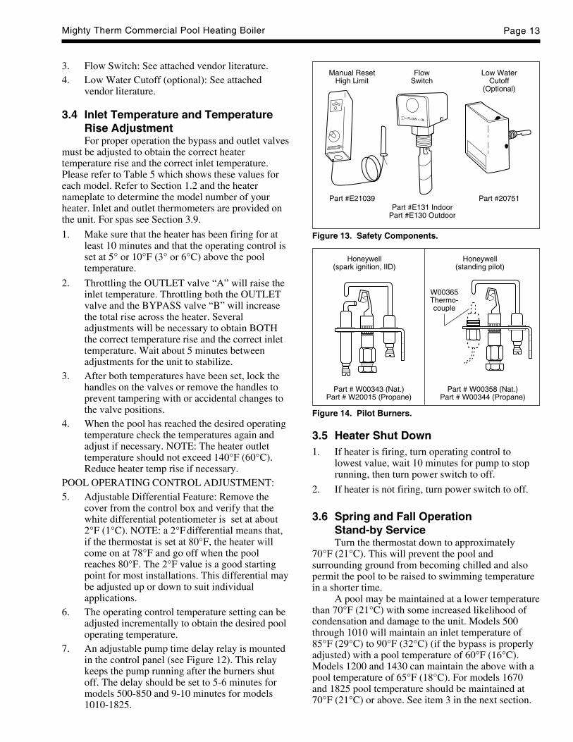
3. Flow Switch: See attached vendor literature.4. Low Water Cutoff (optional): See attached
vendor literature.
3.4 Inlet Temperature and TemperatureRise AdjustmentFor proper operation the bypass and outlet valves
must be adjusted to obtain the correct heatertemperature rise and the correct inlet temperature.Please refer to Table 5 which shows these values foreach model. Refer to Section 1.2 and the heaternameplate to determine the model number of yourheater. Inlet and outlet thermometers are provided onthe unit. For spas see Section 3.9.
1. Make sure that the heater has been firing for atleast 10 minutes and that the operating control isset at 5° or 10°F (3° or 6°C) above the pooltemperature.
2. Throttling the OUTLET valve “A” will raise theinlet temperature. Throttling both the OUTLETvalve and the BYPASS valve “B” will increasethe total rise across the heater. Severaladjustments will be necessary to obtain BOTHthe correct temperature rise and the correct inlettemperature. Wait about 5 minutes betweenadjustments for the unit to stabilize.
3. After both temperatures have been set, lock thehandles on the valves or remove the handles toprevent tampering with or accidental changes tothe valve positions.
4. When the pool has reached the desired operatingtemperature check the temperatures again andadjust if necessary. NOTE: The heater outlettemperature should not exceed 140°F (60°C).Reduce heater temp rise if necessary.
POOL OPERATING CONTROL ADJUSTMENT:5. Adjustable Differential Feature: Remove the
cover from the control box and verify that thewhite differential potentiometer is set at about2°F (1°C). NOTE: a 2°F differential means that,if the thermostat is set at 80°F, the heater willcome on at 78°F and go off when the poolreaches 80°F. The 2°F value is a good startingpoint for most installations. This differential maybe adjusted up or down to suit individualapplications.
6. The operating control temperature setting can beadjusted incrementally to obtain the desired pooloperating temperature.
7. An adjustable pump time delay relay is mountedin the control panel (see Figure 12). This relaykeeps the pump running after the burners shutoff. The delay should be set to 5-6 minutes formodels 500-850 and 9-10 minutes for models1010-1825.
Figure 13. Safety Components.
Manual ResetHigh Limit
FlowSwitch
Low WaterCutoff
(Optional)
Part #E21039Part #E131 Indoor
Part #E130 Outdoor
Part #20751
Figure 14. Pilot Burners.
Honeywell(spark ignition, IID)
Honeywell(standing pilot)
Part # W00358 (Nat.)Part # W00344 (Propane)
3.5 Heater Shut Down1. If heater is firing, turn operating control to
lowest value, wait 10 minutes for pump to stoprunning, then turn power switch to off.
2. If heater is not firing, turn power switch to off.
3.6 Spring and Fall OperationStand-by ServiceTurn the thermostat down to approximately
70°F (21°C). This will prevent the pool andsurrounding ground from becoming chilled and alsopermit the pool to be raised to swimming temperaturein a shorter time.
A pool may be maintained at a lower temperaturethan 70°F (21°C) with some increased likelihood ofcondensation and damage to the unit. Models 500through 1010 will maintain an inlet temperature of85°F (29°C) to 90°F (32°C) (if the bypass is properlyadjusted) with a pool temperature of 60°F (16°C).Models 1200 and 1430 can maintain the above with apool temperature of 65°F (18°C). For models 1670and 1825 pool temperature should be maintained at70°F (21°C) or above. See item 3 in the next section.
Part # W00343 (Nat.)Part # W20015 (Propane)
W00365Thermo-couple
LAARS HEATING SYSTEMSPage 14
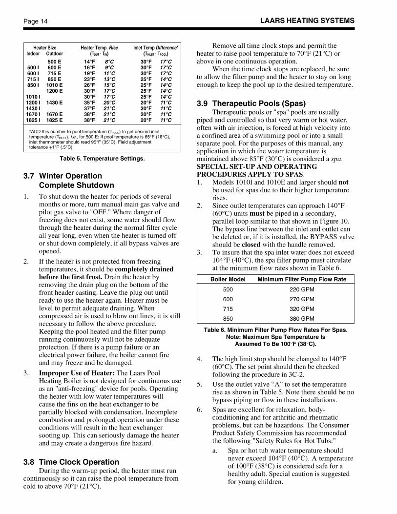
Table 5. Temperature Settings.
3.7 Winter OperationComplete Shutdown
1. To shut down the heater for periods of severalmonths or more, turn manual main gas valve andpilot gas valve to "OFF." Where danger offreezing does not exist, some water should flowthrough the heater during the normal filter cycleall year long, even when the heater is turned offor shut down completely, if all bypass valves areopened.
2. If the heater is not protected from freezingtemperatures, it should be completely drainedbefore the first frost. Drain the heater byremoving the drain plug on the bottom of thefront header casting. Leave the plug out untilready to use the heater again. Heater must belevel to permit adequate draining. Whencompressed air is used to blow out lines, it is stillnecessary to follow the above procedure.Keeping the pool heated and the filter pumprunning continuously will not be adequateprotection. If there is a pump failure or anelectrical power failure, the boiler cannot fireand may freeze and be damaged.
3. Improper Use of Heater: The Laars PoolHeating Boiler is not designed for continuous useas an "anti-freezing" device for pools. Operatingthe heater with low water temperatures willcause the fins on the heat exchanger to bepartially blocked with condensation. Incompletecombustion and prolonged operation under theseconditions will result in the heat exchangersooting up. This can seriously damage the heaterand may create a dangerous fire hazard.
3.8 Time Clock OperationDuring the warm-up period, the heater must run
continuously so it can raise the pool temperature fromcold to above 70°F (21°C).
Remove all time clock stops and permit theheater to raise pool temperature to 70°F (21°C) orabove in one continuous operation.
When the time clock stops are replaced, be sureto allow the filter pump and the heater to stay on longenough to keep the pool up to the desired temperature.
3.9 Therapeutic Pools (Spas)Therapeutic pools or "spa" pools are usually
piped and controlled so that very warm or hot water,often with air injection, is forced at high velocity intoa confined area of a swimming pool or into a smallseparate pool. For the purposes of this manual, anyapplication in which the water temperature ismaintained above 85°F (30°C) is considered a spa.SPECIAL SET-UP AND OPERATINGPROCEDURES APPLY TO SPAS.1. Models 1010I and 1010E and larger should not
be used for spas due to their higher temperaturerises.
2. Since outlet temperatures can approach 140°F(60°C) units must be piped in a secondary,parallel loop similar to that shown in Figure 10.The bypass line between the inlet and outlet canbe deleted or, if it is installed, the BYPASS valveshould be closed with the handle removed.
3. To insure that the spa inlet water does not exceed104°F (40°C), the spa filter pump must circulateat the minimum flow rates shown in Table 6.
Boiler Model Minimum Filter Pump Flow Rate
500 220 GPM
600 270 GPM
715 320 GPM
850 380 GPM
Table 6. Minimum Filter Pump Flow Rates For Spas.Note: Maximum Spa Temperature Is
Assumed To Be 100°F (38°C).
4. The high limit stop should be changed to 140°F(60°C). The set point should then be checkedfollowing the procedure in 3C-2.
5. Use the outlet valve “A” to set the temperaturerise as shown in Table 5. Note there should be nobypass piping or flow in these installations.
6. Spas are excellent for relaxation, body-conditioning and for arthritic and rheumaticproblems, but can be hazardous. The ConsumerProduct Safety Commission has recommendedthe following "Safety Rules for Hot Tubs:"a. Spa or hot tub water temperature should
never exceed 104°F (40°C). A temperatureof 100°F (38°C) is considered safe for ahealthy adult. Special caution is suggestedfor young children.
Heater Size Heater Temp. Rise Inlet Temp Difference*Indoor Outdoor (TOUT - TIN) (TINLET - TPOOL)
500 E 14°F 8°C 30°F 17°C500 I 600 E 16°F 9°C 30°F 17°C600 I 715 E 19°F 11°C 30°F 17°C715 I 850 E 23°F 13°C 25°F 14°C850 I 1010 E 26°F 15°C 25°F 14°C
1200 E 30°F 17°C 25°F 14°C1010 I 30°F 17°C 25°F 14°C1200 I 1430 E 35°F 20°C 20°F 11°C1430 I 37°F 21°C 20°F 11°C1670 I 1670 E 38°F 21°C 20°F 11°C1825 I 1825 E 38°F 21°C 20°F 11°C
*ADD this number to pool temperature (TPOOL) to get desired inlettemperature (TINLET). i.e., for 500 E: If pool temperature is 65°F (18°C),inlet thermometer should read 95°F (35°C). Field adjustmenttolerance +_1°F (.5°C).
Mighty Therm Commercial Pool Heating Boiler Page 15
b. Drinking of alcoholic beverages before orduring spa or hot tub use can causedrowsiness which could lead tounconsciousness and subsequently result indrowning.
c. Pregnant women beware! Soaking in waterabove 102°F (39°C) can cause fetal damageduring the first three months of pregnancy(resulting in the birth of a brain-damaged ordeformed child). Pregnant women shouldstick to the 100°F (38°C) maximum rule.
d. Before entering the spa or hot tub, usersshould check the water temperature with anaccurate thermometer; spa or hot tubthermostats may err in regulating watertemperatures by as much as four degreesFahrenheit (2.2°C).
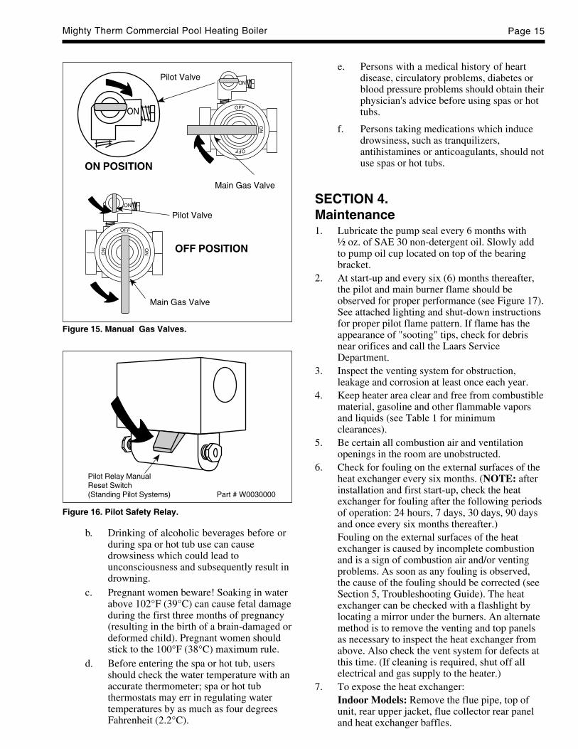
Figure 16. Pilot Safety Relay.
Pilot ResetSwitch
e. Persons with a medical history of heartdisease, circulatory problems, diabetes orblood pressure problems should obtain theirphysician's advice before using spas or hottubs.
f. Persons taking medications which inducedrowsiness, such as tranquilizers,antihistamines or anticoagulants, should notuse spas or hot tubs.
SECTION 4.Maintenance1. Lubricate the pump seal every 6 months with
½ oz. of SAE 30 non-detergent oil. Slowly addto pump oil cup located on top of the bearingbracket.
2. At start-up and every six (6) months thereafter,the pilot and main burner flame should beobserved for proper performance (see Figure 17).See attached lighting and shut-down instructionsfor proper pilot flame pattern. If flame has theappearance of "sooting" tips, check for debrisnear orifices and call the Laars ServiceDepartment.
3. Inspect the venting system for obstruction,leakage and corrosion at least once each year.
4. Keep heater area clear and free from combustiblematerial, gasoline and other flammable vaporsand liquids (see Table 1 for minimumclearances).
5. Be certain all combustion air and ventilationopenings in the room are unobstructed.
6. Check for fouling on the external surfaces of theheat exchanger every six months. (NOTE: afterinstallation and first start-up, check the heatexchanger for fouling after the following periodsof operation: 24 hours, 7 days, 30 days, 90 daysand once every six months thereafter.)Fouling on the external surfaces of the heatexchanger is caused by incomplete combustionand is a sign of combustion air and/or ventingproblems. As soon as any fouling is observed,the cause of the fouling should be corrected (seeSection 5, Troubleshooting Guide). The heatexchanger can be checked with a flashlight bylocating a mirror under the burners. An alternatemethod is to remove the venting and top panelsas necessary to inspect the heat exchanger fromabove. Also check the vent system for defects atthis time. (If cleaning is required, shut off allelectrical and gas supply to the heater.)
7. To expose the heat exchanger:Indoor Models: Remove the flue pipe, top ofunit, rear upper jacket, flue collector rear paneland heat exchanger baffles.
Pilot Relay ManualReset Switch(Standing Pilot Systems) Part # W0030000
Figure 15. Manual Gas Valves.
Pilot Valve
Main Gas Valve
Pilot Valve
Main Gas Valve
ON POSITION
OFF POSITION

LAARS HEATING SYSTEMSPage 16
Outdoor Models: Remove vent top assembly,rear upper jacket, flue collector rear panel andheat exchanger baffles.
8. To remove all burners:It is usually more convenient to remove theburner tray assembly. Disconnect sensor wire,ignition cable (or thermocouple generator) andpilot gas line. Disconnect manifold inlet union(s).Remove the four (4) retaining screws. Grasp themanifold pipe and slide out the burner tray.
CautionBlack carbon or green soot on a dirty heatexchanger can, under certain conditions, beignited by a random spark or open flame. Toprevent this unlikely occurrence, dampen thesoot deposits with wet brush or fine waterspray before servicing or cleaning the heatexchanger.
9. Clean heat exchanger using a wire brush toremove soot and loose scale from the unit. Cleanfallen debris from bottom of heater. Make sureburner ports are clear and pilot assembly is freeof debris.
10. Reassemble in reverse order and be sure the heatexchanger baffles are replaced.
11. The gas and electric controls installed on theheater are engineered for both dependableoperation and long life, but the properfunctioning of these components is necessary forsafe operation of the heater. It is stronglyrecommended that the basic items be checked bya competent serviceman every year and replacedwhen necessary. The basic controls are:
a. Water temperature controls.
b. Pilot safety system.
c. Automatic electric gas valve(s)
d. Flow switch.
12. Low water cutoffs should be inspected every six(6) months, when provided.
NOTE: The warranty does not cover anydamage caused by lack of required maintenanceor improper operating practices.
13. Pool Water Chemistry
The mineral content of the pool water increasesevery day. This is due to the natural evaporationwhich removes only distilled water and leaves theminerals behind. The regular addition of algicidaland sanitizing chemicals also adds greatly to themineral content of the pool. If the concentration ofminerals in the pool is permitted to become too
Figure 17. Main Burner Flame Pattern.
high, the minerals will precipitate out of the waterand deposit onto the walls of the pool, in the filterand in the tubes of the heat exchanger.
For this reason it is very advantageous to drainthe pool regularly (at least every two years). Thisprecautionary measure will save the cost ofexpensive repairs to the finish, filter system andheater.
Another important safety precaution - alwayskeep the pH of the pool water between 7.3 and7.7. This will add years to the life of the poolfinish, filter system and heater.
Most algicidal and sanitizing chemicals containsodium hypochlorite, while others containcalcium hypochlorite. Sodium is not a scalingchemical but calcium is. When using calciumhypochlorite it is especially important tofrequently check the pH of the pool and tochange the pool water when the dissolved solidsindicate an excessive mineral content.
SECTION 5.Troubleshooting
For proper service and problem diagnosis of theheater and heater system, the following tools arerequired:
a. Gas pressure test kit with range from zero to 14W.C. Either a slack tube manometer or anaccurate gas pressure gauge is acceptable withproper adapters to connect to the availablefittings in the line and on the gas valve.
b. Multi-meter with the following ranges:
0 to 500 volts A.C.
0 to 1000 ohms continuity.
0 to 50 millivolts.
c. Tube cleaning kit consisting of reamer, stainlesssteel brush, speed handle and handle extensions.
d. A pool thermometer with a proper range.
e. A pressure gauge with proper range.

Mighty Therm Commercial Pool Heating Boiler Page 17
1. Symptom: heater is pounding, knocking or emitting steam from relief valvePossible Cause What to Do
A. Low or no water flow A. Is the heater wired into the filter pump circuit so that the heater cannot fire(most likely). unless the pump is running?
Check to see that all valves in system are open to be sure that water cancirculate through the heater.
Check pool filter, clean if clogged.
Examine heater pump for clogged or frozen impeller.
Check flow switch for proper operation and range setting.
B. Debris from system piping B. Remove header covers. Examine all tubes and waterways. Clean out tubes.is blocking tubes. Use new gaskets when reassembling.
C. Scale has formed in tubes C. Clean tubes with tube cleaning kit. Determine hardness. Check water flow, andfrom high mineral content. clean pool filter.
2. Symptom: heater will not fireA. Heater not getting power. A. Check to see that power switch is "ON." Use testing device to trace power to
heater power source. Check fuse and secondary voltage in heater control.
B. Operating or safety control has B. Turn off power. Check continuity across terminals of each operating and safetyopened circuit to electric gas valve. control switch up to the electric gas valve. Replace defective control.
C. Pilot flame is out. C. Relight pilot per instruction.
D. Manual reset device has tripped. D. Reset pilot safety and all manual reset safety switches. Follow instructions forstart-up.
E. No gas pressure to burners. E. Trace gas line to service shutoff cock. If service cock is open, trace gas line tometer. If no pressure is present at meter, call for public utility service. If gas ispresent in heater inlet, check pressures in following sequence: (1) downstreamfrom pressure regulator; (2) downstream from electric gas valve. Replace oradjust as necessary.
F. Electric gas valve operator is F. Disconnect wiring harness at gas valve terminals. Check continuity of actuatorburned out or shorted. coil. If open circuit or short is indicated, replace coil or operator.
G. Pump does not run. G. Operate in manual. Check power to pump from relay, Check that pump/motor isfree to rotate. Replace relay or motor as necessary.
H. Pump runs, but flow switch H. Check continuity across flow switch. Inspect paddle for proper movement.not closing. Adjust flow range setting.
I. Field interlock open. I. Jumper terminals and isolate problem in other equipment.
3. Symptom: pressure relief valve leaking intermittently or steadilyA. Faulty relief valve. A. Replace with a new relief valve with proper setting (see rating plate).
4. Symptom: soot in flueways or in tubes, or noxious fumes from bad combustionA. Combustion air supply to heater A. Check air supply opening. Look for debris in screen or louvre which covers
room is inadequate. combustion air opening, or for objects blocking the opening.
B. Stack or vent is blocked or restrictive. B. Look for blocked stack and excessive number of elbows in stack or excessivelength of horizontal runs.
C. Severe downdraft is causing C. Check for (1) proper vent cap on stack; (2) adequate height of stack abovespillage of flue products into room. roof; (3) equipment exhausting air from inside of building; and (4) proper
installation of draft diverter.
D. Gas pressure to burners is excessive. D. Check gas pressure with manometer, and adjust with heater firing at full rate.
E. Heater not fitted for the fuel supplied. E. See nameplate for correct fuel.
F. Heater installed at high altitude F. Installations at altitudes in excess of 2000 ft. above sea level are subject towithout proper derating. jurisdiction of the local inspection authorities. Check orifice size, contact your
dealer or factory for proper size.
5. Symptom: water dripping in fireboxA. Tube in heat exchanger has A. Tube failure is almost always caused by scale formation in the tube, or
overheated and ruptured. inadequate water flow through the heater.
B. Heater is condensing from low B. Check bypass valve adjustment.inlet temperature.
LAARS HEATING SYSTEMSPage 18
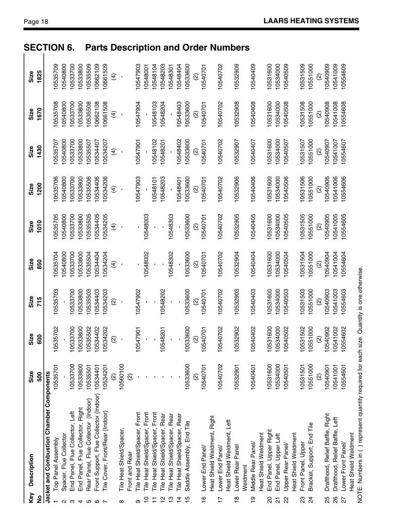
SECTION 6. Parts Description and Order Numbers
Key
Des
crip
tio
nS
ize
Siz
eS
ize
Siz
eS
ize
Siz
eS
ize
Siz
eS
ize
No
500
600
715
850
1010
1200
1430
1670
1825
Jack
et a
nd
Co
mb
ust
ion
Ch
amb
er C
om
po
nen
ts1
Top
Pan
el A
ssem
bly
1053
5701
1053
5702
1053
5703
1053
5704
1053
5705
1053
5706
1053
5707
1053
5708
1053
5709
2S
pace
r, F
lue
Col
lect
or-
--
1054
0800
1054
0800
1054
0800
1054
0800
1054
0800
1054
0800
3E
nd P
anel
, Flu
e C
olle
ctor
, Lef
t10
5337
0010
5337
0010
5337
0010
5337
0010
5337
0010
5337
0010
5337
0010
5337
0010
5337
004
End
Pan
el, F
lue
Col
lect
or, R
ight
1053
3800
1053
3800
1053
3800
1053
3800
1053
3800
1053
3800
1053
3800
1053
3800
1053
3800
5R
ear
Pan
el, F
lue
Col
lect
or {
Indo
or}
1053
5501
1053
5502
1053
5503
1053
5504
1053
5505
1053
5506
1053
5507
1053
5508
1053
5509
6F
ront
Sup
port
, Flu
e C
olle
ctor
{In
door
}10
5344
0110
5344
0210
5344
0310
5344
0410
5344
0510
5344
0610
5344
0710
6621
0810
6621
097
Tile
Cov
er, F
ront
/Rea
r {I
ndoo
r}10
5342
0110
5342
0210
5342
0310
5342
0410
5342
0510
5342
0610
5342
0710
6615
0810
6615
09(2
)(2
)(2
)(4
)(4
)(4
)(4
)(4
)(4
)8
Tile
Hea
t Shi
eld/
Spa
cer,
1056
0100
--
--
--
--
Fro
nt a
nd R
ear
(2)
9T
ile H
eat S
hiel
d/S
pace
r, F
ront
-10
5479
0110
5479
02-
-10
5479
0310
5479
0110
5479
0410
5479
0310
Tile
Hea
t Shi
eld/
Spa
cer,
Fro
nt-
--
1054
8002
1054
8003
--
-10
5480
0111
Tile
Hea
t Shi
eld/
Spa
cer,
Fro
nt-
--
--
1054
8101
1054
8102
1054
8103
1054
8104
12T
ile H
eat S
hiel
d/S
pace
r, R
ear
-10
5482
0110
5482
02-
-10
5482
0310
5482
0110
5482
0410
5482
0313
Tile
Hea
t Shi
eld/
Spa
cer,
Rea
r-
--
1054
8302
1054
8303
--
-10
5483
0114
Tile
Hea
t Shi
eld/
Spa
cer,
Rea
r-
--
--
1054
8401
1054
8402
1054
8403
1054
8404
15S
addl
e A
ssem
bly,
End
Tile
1053
3600
1053
3600
1053
3600
1053
3600
1053
3600
1053
3600
1053
3600
1053
3600
1053
3600
(2)
(2)
(2)
(2)
(2)
(2)
(2)
(2)
(2)
16Lo
wer
End
Pan
el/
1054
0701
1054
0701
1054
0701
1054
0701
1054
0701
1054
0701
1054
0701
1054
0701
1054
0701
Hea
t Shi
eld
Wel
dmen
t, R
ight
17Lo
wer
End
Pan
el/
1054
0702
1054
0702
1054
0702
1054
0702
1054
0702
1054
0702
1054
0702
1054
0702
1054
0702
Hea
t Shi
eld
Wel
dmen
t, Le
ft18
Low
er R
ear
Pan
el10
5329
0110
5329
0210
5329
0310
5329
0410
5329
0510
5329
0610
5329
0710
5329
0810
5329
09W
eldm
ent
19M
iddl
e R
ear
Pan
el/
1054
0401
1054
0402
1054
0403
1054
0404
1054
0405
1054
0406
1054
0407
1054
0408
1054
0409
Hea
t Shi
eld
Wel
dmen
t20
End
Pan
el, U
pper
Rig
ht10
5316
0010
5316
0010
5316
0010
5316
0010
5316
0010
5316
0010
5316
0010
5316
0010
5316
0021
End
Pan
el, U
pper
Lef
t10
5340
0010
5340
0010
5340
0010
5340
0010
5340
0010
5340
0010
5340
0010
5340
0010
5340
0022
Upp
er R
ear
Pan
el/
1054
0501
1054
0502
1054
0503
1054
0504
1054
0505
1054
0506
1054
0507
1054
0508
1054
0509
Hea
t Shi
eld
Wel
dmen
t23
Fro
nt P
anel
, Upp
er10
5315
0110
5315
0210
5315
0310
5315
0410
5315
0510
5315
0610
5315
0710
5315
0810
5315
0924
Bra
cket
, Sup
port
, End
Tile
1055
1000
1055
1000
1055
1000
1055
1000
1055
1000
1055
1000
1055
1000
1055
1000
1055
1000
(2)
(2)
(2)
(2)
(2)
(2)
(2)
(2)
(2)
25D
rafth
ood,
Rel
ief B
affle
, Rig
ht10
5409
0110
5409
0210
5409
0310
5409
0410
5409
0510
5409
0610
5409
0710
5409
0810
5409
0926
Dra
fthoo
d, R
elie
f Baf
fle, L
eft
1054
1001
1054
1002
1054
1003
1054
1004
1054
1005
1054
1006
1054
1007
1054
1008
1054
1009
27Lo
wer
Fro
nt P
anel
/10
5546
0110
5546
0210
5546
0310
5546
0410
5546
0510
5546
0610
5546
0710
5546
0810
5546
09H
eat S
hiel
d W
eldm
ent
NO
TE
: Num
bers
in (
) re
pres
ent q
uant
ity r
equi
red
for
each
siz
e. Q
uant
ity is
one
oth
erw
ise.
Mighty Therm Commercial Pool Heating Boiler Page 19
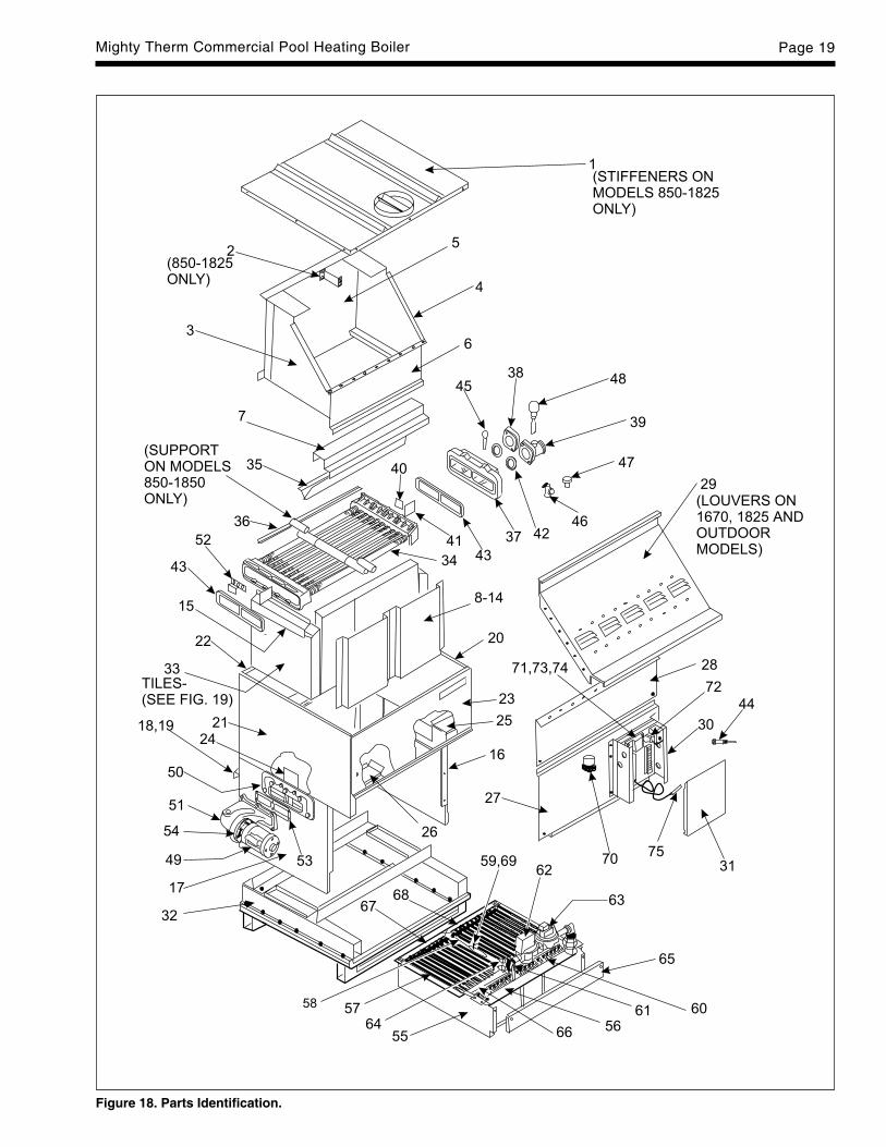
Figure 18. Parts Identification.
LAARS HEATING SYSTEMSPage 20K
eyD
escr
ipti
on
Siz
eS
ize
Siz
eS
ize
Siz
eS
ize
Siz
eS
ize
Siz
eN
o50
060
071
585
010
1012
0014
3016
7018
25
28M
iddl
e F
ront
Pan
el {
Indo
or}
1055
4401
1055
4402
1055
4403
1055
4404
1055
4405
1055
4406
1055
4407
1066
2008
1066
2009
29S
wee
p S
heet
, Flu
e C
olle
ctor
{In
door
}10
5339
0110
5339
0210
5339
0310
5339
0410
5339
0510
5339
0610
5339
0710
6622
0810
6622
0930
Con
trol
Box
Wel
dmen
t10
5458
0010
5458
0010
5458
0010
5458
0010
5458
0010
5458
0010
5458
0010
5458
0010
5458
0031
Con
trol
Box
Cov
er {
Indo
or}
1054
7200
1054
7200
1054
7200
1054
7200
1054
7200
1054
7200
1054
7200
1054
7200
1054
7200
32B
ase/
Tile
Sup
port
Ass
embl
y {I
ndoo
r}10
5369
0110
5369
0210
5369
0310
5369
0410
5369
0510
5369
0610
5369
0710
5369
0810
5369
0933
Tile
Ass
embl
ies
{R
efer
to
Fig
ure
20
for
con
fig
ura
tio
ns
and
Par
t N
um
ber
s}O
pti
on
al It
ems
Non
-Com
bust
ible
Bas
e {R
ail}
1053
9000
1053
9000
1053
9000
1053
9000
1053
9000
1053
9000
1053
9000
1053
9000
1053
9000
(2)
(2)
(2)
(2)
(2)
(2)
(2)
(2)
(2)
Wat
er S
yste
m34
8-T
ube
Ass
embl
y, C
oppe
r T
ubes
/10
5347
0110
5347
0210
5347
0310
5347
0410
5347
0510
5347
0610
5347
07-
-C
ast I
ron
Tub
s {I
ndoo
r}8-
Tub
e A
ssem
bly,
Cop
per
Tub
es/
1054
2901
1054
2902
1054
2903
1054
2904
1054
2905
1054
2906
1054
2907
--
Bro
nze
Tub
s {I
ndoo
r}8-
Tub
e A
ssem
bly,
CU
-NI T
ubes
/10
5536
0110
5536
0210
5536
0310
5536
0410
5536
0510
5536
0610
5536
07-
-C
ast I
ron
Tub
s {I
ndoo
r}8-
Tub
e A
ssem
bly,
CU
-NI T
ubes
/10
5537
0110
5537
0210
5537
0310
5537
0410
5537
0510
5537
0610
5537
07-
-B
ronz
e T
ubs
{Ind
oor}
10-T
ube
Ass
embl
y, C
oppe
r T
ube/
--
--
--
-10
6659
0810
6659
09C
ast I
ron
Tub
s {I
ndoo
r}10
-Tub
e A
ssem
bly,
Cop
per
Tub
e/-
--
--
--
2000
1108
2000
1109
Bro
nze
Tub
s {I
ndoo
r}10
-Tub
e A
ssem
bly,
CU
-NI T
ubes
/-
--
--
--
2000
1008
2000
1009
Cas
t Iro
n T
ubs
{Ind
oor}
10-T
ube
Ass
embl
y, C
U-N
I Tub
es/
--
--
--
-10
6704
0810
6704
09B
ronz
e T
ubs
{Ind
oor}
35B
affle
, Hea
t Exc
hang
er F
ront
/10
5343
0110
5343
0210
5343
0310
5343
0410
5343
0510
5343
0610
5343
0720
0201
0820
0201
09R
ear
{Ind
oor}
(2)
(2)
(2)
(4)
(4)
(4)
(4)
(4)
(4)
36B
affle
, Hea
t Exc
hang
er {
8-T
ube}
1053
4601
1053
4602
1053
4603
1053
4604
1053
4605
1053
4606
1053
4607
--
(7)
(14)
(14)
(14)
(14)
(28)
(28)
--
Baf
fle, H
eat E
xcha
nger
{10
-Tub
e}-
--
--
--
1066
7708
1066
7709
(28)
(14)
Baf
fle, H
eat E
xcha
nger
{10
-Tub
e}-
--
--
--
-10
6677
02(1
4)
NO
TE
: Num
bers
in (
) re
pres
ent q
uant
ity r
equi
red
for
each
siz
e. Q
uant
ity is
one
oth
erw
ise.
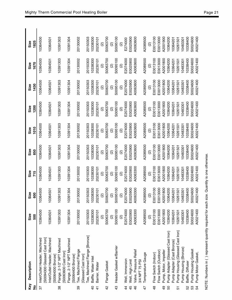
Mighty Therm Commercial Pool Heating Boiler Page 21
Key
Des
crip
tio
nS
ize
Siz
eS
ize
Siz
eS
ize
Siz
eS
ize
Siz
eS
ize
No
500
600
715
850
1010
1200
1430
1670
1825
37In
let/O
utle
t Hea
der,
Mac
hine
d10
3645
0010
3645
0010
3645
0010
3645
0010
3645
0010
3645
0010
3645
0010
3645
0010
3645
00[S
0094
300
Gla
ssed
Cas
t Iro
n]In
let/O
utle
t Hea
der,
Mac
hine
d10
3645
0110
3645
0110
3645
0110
3645
0110
3645
0110
3645
0110
3645
0110
3645
0110
3645
01[S
0064
000
Bro
nze]
38F
lang
e, 2
-1/2
" N
PT
Mac
hine
d10
3913
0310
3913
0310
3913
0310
3913
0310
3913
0310
3913
0310
3913
0310
3913
0310
3913
03[S
0063
600
Cas
t Iro
n]F
lang
e, 2
-1/2
" N
PT
Mac
hine
d10
3913
0410
3913
0410
3913
0410
3913
0410
3913
0410
3913
0410
3913
0410
3913
0410
3913
04[S
0064
400
Bro
nze]
39T
ee, M
achi
ned
Fla
nge
2013
0002
2013
0002
2013
0002
2013
0002
2013
0002
2013
0002
2013
0002
2013
0002
2013
0002
[Gla
ssed
Cas
t Iro
n]T
ee, M
achi
ned
Fla
nge
[Bro
nze]
2015
0303
2015
0303
2015
0303
2015
0303
2015
0303
2015
0303
2015
0303
2015
0303
2015
0303
40B
affle
, Wat
er In
let
1033
8300
1033
8300
1033
8300
1033
8300
1033
8300
1033
8300
1033
8300
1033
8300
1033
8300
41B
arrie
r, W
ater
2023
0101
2023
0101
2023
0101
2023
0101
2023
0101
2023
0101
2023
0101
2023
0101
2023
0101
(2)
(2)
(2)
(2)
(2)
(2)
(2)
(2)
(2)
42F
lang
e G
aske
tS
0063
700
S00
6370
0S
0063
700
S00
6370
0S
0063
700
S00
6370
0S
0063
700
S00
6370
0S
0063
700
(2)
(2)
(2)
(2)
(2)
(2)
(2)
(2)
(2)
43H
eade
r G
aske
t w/B
arrie
rS
0095
100
S00
9510
0S
0095
100
S00
9510
0S
0095
100
S00
9510
0S
0095
100
S00
9510
0S
0095
100
(2)
(2)
(2)
(2)
(2)
(2)
(2)
(2)
(2)
44W
ell,
Imm
ersi
onE
2074
000
E20
7400
0E
2074
000
E20
7400
0E
2074
000
E20
7400
0E
2074
000
E20
7400
0E
2740
0045
Wel
l, H
igh
Lim
itE
0025
900
E00
2590
0E
0025
900
E00
2590
0E
0025
900
E00
2590
0E
0025
900
E00
2590
0E
0025
900
46V
alve
, Pre
ssur
e R
elie
fA
0063
300
A00
6330
0A
0063
300
A00
6360
0A
0063
600
A00
6360
0A
0063
600
A00
6360
0A
0063
600
3/4
NP
T 7
5 P
SI
47T
empe
ratu
re G
auge
A20
8950
0A
2089
500
A20
8950
0A
2089
500
A20
8950
0A
2089
500
A20
8950
0A
2089
500
A20
8950
0(2
)(2
)(2
)(2
)(2
)(2
)(2
)(2
)(2
)48
Flo
w S
witc
h {I
ndoo
r}E
0013
100
E00
1310
0E
0013
100
E00
1310
0E
0013
100
E00
1310
0E
0013
100
E00
1310
0E
0013
100
Flo
w S
witc
h {O
utdo
or}
E00
1300
0E
0013
000
E00
1300
0E
0013
000
E00
1300
0E
0013
000
E00
1300
0E
0013
000
E00
1300
049
Pum
p, M
otor
, Im
pelle
rA
2001
800
A20
0180
0A
2001
800
A20
0180
0A
2001
800
A20
0180
0A
2001
800
A20
0180
0A
2001
900
50P
ump
Ada
pter
{G
lass
ed C
ast I
ron}
1036
4200
1036
4200
1036
4200
1036
4200
1036
4200
1036
4200
1036
4200
1036
4200
1036
4200
Pum
p A
dapt
er {
Cas
t Bro
nze}
1036
4201
1036
4201
1036
4201
1036
4201
1036
4201
1036
4201
1036
4201
1036
4201
1036
4201
51P
ump
Hou
sing
{G
lass
ed C
ast I
ron}
1026
1501
1026
1501
1026
1501
1026
1501
1026
1501
1026
1501
1026
1501
1026
1501
1026
1501
Pum
p H
ousi
ng {
Bro
nze}
1048
3301
1048
3301
1048
3301
1048
3301
1048
3301
1048
3301
1048
3301
1048
3301
1048
3301
52B
affle
, Diff
user
1033
8400
1033
8400
1033
8400
1033
8400
1033
8400
1033
8400
1033
8400
1033
8400
1033
8400
53P
ump
Hou
sing
Gas
ket
S00
2460
0S
0024
600
S00
2460
0S
0024
600
S00
2460
0S
0024
600
S00
2460
0S
0024
600
S00
2460
054
Pum
p M
otor
Gas
ket,
A00
2140
0A
0021
400
A00
2140
0A
0021
400
A00
2140
0A
0021
400
A00
2140
0A
0021
400
A00
2140
0
NO
TE
: Num
bers
in (
) re
pres
ent q
uant
ity r
equi
red
for
each
siz
e. Q
uant
ity is
one
oth
erw
ise.
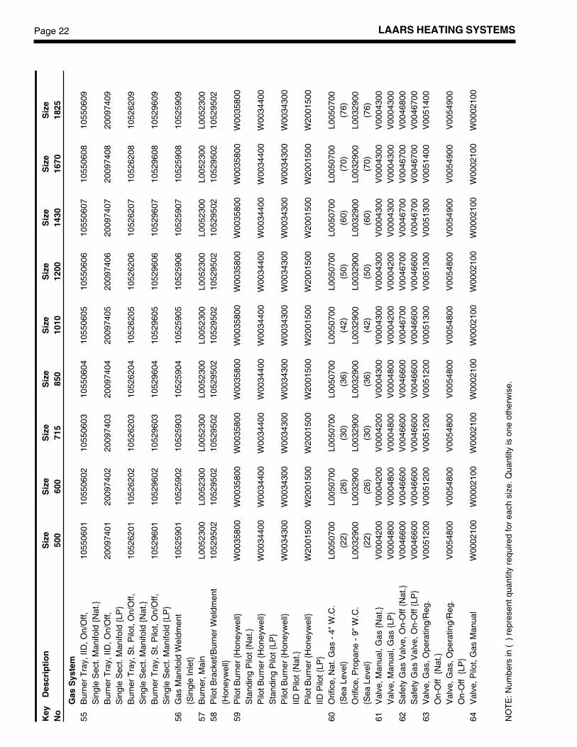
LAARS HEATING SYSTEMSPage 22
Key
Des
crip
tio
nS
ize
Siz
eS
ize
Siz
eS
ize
Siz
eS
ize
Siz
eS
ize
No
500
600
715
850
1010
1200
1430
1670
1825
Gas
Sys
tem
55B
urne
r T
ray,
IID
, On/
Off,
1055
0601
1055
0602
1055
0603
1055
0604
1055
0605
1055
0606
1055
0607
1055
0608
1055
0609
Sin
gle
Sec
t. M
anifo
ld {
Nat
.}B
urne
r T
ray,
IID
, On/
Off,
2009
7401
2009
7402
2009
7403
2009
7404
2009
7405
2009
7406
2009
7407
2009
7408
2009
7409
Sin
gle
Sec
t. M
anifo
ld {
LP}
Bur
ner
Tra
y, S
t. P
ilot,
On/
Off,
1052
6201
1052
6202
1052
6203
1052
6204
1052
6205
1052
6206
1052
6207
1052
6208
1052
6209
Sin
gle
Sec
t. M
anifo
ld {
Nat
.}B
urne
r T
ray,
St.
Pilo
t, O
n/O
ff,10
5296
0110
5296
0210
5296
0310
5296
0410
5296
0510
5296
0610
5296
0710
5296
0810
5296
09S
ingl
e S
ect.
Man
ifold
{LP
}56
Gas
Man
ifold
Wel
dmen
t10
5259
0110
5259
0210
5259
0310
5259
0410
5259
0510
5259
0610
5259
0710
5259
0810
5259
09{S
ingl
e In
let}
57B
urne
r, M
ain
L005
2300
L005
2300
L005
2300
L005
2300
L005
2300
L005
2300
L005
2300
L005
2300
L005
2300
58P
ilot B
rack
et/B
urne
r W
eldm
ent
1052
9502
1052
9502
1052
9502
1052
9502
1052
9502
1052
9502
1052
9502
1052
9502
1052
9502
{Hon
eyw
ell}
59P
ilot B
urne
r {H
oney
wel
l}W
0035
800
W00
3580
0W
0035
800
W00
3580
0W
0035
800
W00
3580
0W
0035
800
W00
3580
0W
0035
800
Sta
ndin
g P
ilot {
Nat
.}P
ilot B
urne
r {H
oney
wel
l}W
0034
400
W00
3440
0W
0034
400
W00
3440
0W
0034
400
W00
3440
0W
0034
400
W00
3440
0W
0034
400
Sta
ndin
g P
ilot {
LP}
Pilo
t Bur
ner
{Hon
eyw
ell}
W00
3430
0W
0034
300
W00
3430
0W
0034
300
W00
3430
0W
0034
300
W00
3430
0W
0034
300
W00
3430
0IID
Pilo
t {N
at.}
Pilo
t Bur
ner
{Hon
eyw
ell}
W20
0150
0W
2001
500
W20
0150
0W
2001
500
W20
0150
0W
2001
500
W20
0150
0W
2001
500
W20
0150
0IID
Pilo
t {LP
}60
Orif
ice,
Nat
. Gas
- 4
" W
.C.
L005
0700
L005
0700
L005
0700
L005
0700
L005
0700
L005
0700
L005
0700
L005
0700
L005
0700
{Sea
Lev
el}
(22)
(26)
(30)
(36)
(42)
(50)
(60)
(70)
(76)
Orif
ice,
Pro
pane
- 9
" W
.C.
L003
2900
L003
2900
L003
2900
L003
2900
L003
2900
L003
2900
L003
2900
L003
2900
L003
2900
{Sea
Lev
el}
(22)
(26)
(30)
(36)
(42)
(50)
(60)
(70)
(76)
61V
alve
, Man
ual,
Gas
{N
at.}
V00
0420
0V
0004
200
V00
0420
0V
0004
300
V00
0430
0V
0004
300
V00
0430
0V
0004
300
V00
0430
0V
alve
, Man
ual,
Gas
{LP
}V
0004
800
V00
0480
0V
0004
800
V00
0480
0V
0004
200
V00
0420
0V
0004
300
V00
0430
0V
0004
300
62S
afet
y G
as V
alve
, On-
Off
{Nat
.}V
0046
600
V00
4660
0V
0046
600
V00
4660
0V
0046
700
V00
4670
0V
0046
700
V00
4670
0V
0046
800
Saf
ety
Gas
Val
ve, O
n-O
ff {L
P}
V00
4660
0V
0046
600
V00
4660
0V
0046
600
V00
4660
0V
0046
600
V00
4670
0V
0046
700
V00
4670
063
Val
ve, G
as, O
pera
ting/
Reg
.V
0051
200
V00
5120
0V
0051
200
V00
5120
0V
0051
300
V00
5130
0V
0051
300
V00
5140
0V
0051
400
On-
Off
{N
at.}
Val
ve, G
as, O
pera
ting/
Reg
.V
0054
800
V00
5480
0V
0054
800
V00
5480
0V
0054
800
V00
5480
0V
0054
900
V00
5490
0V
0054
900
On-
Off
{LP
}64
Val
ve, P
ilot,
Gas
Man
ual
W00
0210
0W
0002
100
W00
0210
0W
0002
100
W00
0210
0W
0002
100
W00
0210
0W
0002
100
W00
0210
0
NO
TE
: Num
bers
in (
) re
pres
ent q
uant
ity r
equi
red
for
each
siz
e. Q
uant
ity is
one
oth
erw
ise.
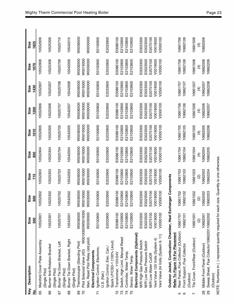
Mighty Therm Commercial Pool Heating Boiler Page 23
Key
Des
crip
tio
nS
ize
Siz
eS
ize
Siz
eS
ize
Siz
eS
ize
Siz
eS
ize
No
500
600
715
850
1010
1200
1430
1670
1825
65M
anifo
ld C
over
Pla
te A
ssem
bly
1055
2901
1055
2902
1055
2903
1055
2904
1055
2905
1055
2906
1055
2907
1055
2908
1055
2909
{Sin
gle
Pilo
t}66
Bur
ner
Ant
i-Rot
atio
n B
rack
et10
5253
0110
5253
0210
5253
0310
5253
0410
5253
0510
5253
0610
5253
0710
5253
0810
5253
09{S
ingl
e P
ilot}
67B
urne
r T
ie D
own
Bra
cket
, Lef
t10
5257
0110
5257
0210
5257
0310
5257
0410
5257
0510
5257
0710
5257
0810
5257
0910
5257
10{S
ingl
e P
ilot}
68B
urne
r T
ie D
own
Bra
cket
, Rig
ht10
5420
0110
5420
0210
5420
0310
5420
0410
5420
0510
5420
0710
5420
0810
5420
0910
5420
10{S
ingl
e P
ilot}
69T
herm
ocou
ple
{Sta
ndin
g P
ilot}
W00
3650
0W
0036
500
W00
3650
0W
0036
500
W00
3650
0W
0036
500
W00
3650
0W
0036
500
W00
3650
070
Pilo
t Sol
enoi
d V
alve
(IID
)W
0019
300W
0019
300
W00
1930
0W
0019
300
W00
1930
0W
0019
300
W00
1930
0W
0019
300
W00
1930
0M
an. R
eset
Pilo
t Rel
ay (
std.
pilo
t)W
0030
000
W00
3000
0W
0030
000
W00
3000
0W
0030
000
W00
3000
0W
0030
000
W00
3000
0W
0030
000
Ele
ctri
cal C
om
po
nen
ts71
Igni
tion
Con
trol
, Ele
ctro
nic,
E01
0090
0E
0100
900
E01
0090
0E
0100
900
E01
0090
0E
0100
900
E01
0090
0E
0100
900
E01
0090
0U
.S. {
Nat
.}Ig
nitio
n C
ontr
ol, E
lec.
Can
./E
2033
900
E20
3390
0E
2033
900
E20
3390
0E
2033
900
E20
3390
0E
2033
900
E20
3390
0E
2033
900
Spa
rk L
P/C
SD
-1 {
100%
Lko
ut}
72T
rans
form
er, 1
15V
/24V
E00
8610
0E
0086
100
E00
8610
0E
0086
100
E00
8610
0E
0086
100
E00
8610
0E
0086
100
E00
8610
073
Sw
itch,
Hig
h Li
mit,
Man
ual R
eset
E21
0390
0E
2103
900
E21
0390
0E
2103
900
E21
0390
0E
2103
900
E21
0390
0E
2103
900
E21
0390
074
Con
trol
ler,
Wat
er T
emp.
E21
0380
0E
2103
800
E21
0380
0E
2103
800
E21
0380
0E
2103
800
E21
0380
0E
2103
800
E21
0380
075
Sen
sor,
Wat
er T
emp.
E21
0360
0E
2103
600
E21
0360
0E
2103
600
E21
0360
0E
2103
600
E21
0360
0E
2103
600
E21
0360
0E
lect
rica
l Co
mp
on
ents
{O
pti
on
al}
M/R
Hig
h G
as P
ress
ure
Sw
itch
E00
2330
0E
0023
300
E00
2330
0E
0023
300
E00
2330
0E
0023
300
E00
2330
0E
0023
300
E00
2330
0M
/R L
ow G
as P
ress
ure
Sw
itch
E00
2350
0E
0023
500
E00
2350
0E
0023
500
E00
2350
0E
0023
500
E00
2350
0E
0023
500
E00
2350
0M
/R L
ow W
ater
Cut
Off
E20
7510
0E
2075
100
E20
7510
0E
2075
100
E20
7510
0E
2075
100
E20
7510
0E
2075
100
E20
7510
0V
ent V
alve
120
Vol
ts {
Sys
tem
4}
V00
1900
0V
0019
000
V00
1900
0V
0019
000
V00
1900
0V
0019
000
V00
1900
0V
0019
000
V00
1900
0V
ent V
alve
24
Vol
ts {
Sys
tem
9, 1
1}V
2000
100
V20
0010
0V
2000
100
V20
0010
0V
2000
100
V20
0010
0V
2000
100
V20
0010
0V
2000
100
Ou
tdo
or
Jack
et, C
om
bu
stio
n C
ham
ber
, Hea
t E
xch
ang
er C
om
po
nen
tsR
efer
To
Fig
ure
19
Fo
r P
lace
men
t5
Rea
r P
anel
, Flu
e C
olle
ctor
{O
utdo
or}
1066
1701
1066
1702
1066
1703
1066
1704
1066
1705
1066
1706
1066
1707
1066
1708
1066
1709
6F
ront
Sup
port
, Flu
e C
olle
ctor
1066
2101
1066
2102
1066
2103
1066
2104
1066
2105
1066
2106
1066
2107
1066
2108
1066
2109
{Out
door
}7
Tile
Cov
er, F
ront
/Rea
r {O
utdo
or}
1066
1501
1066
1502
1066
1503
1066
1504
1066
1505
1066
1506
1066
1507
1066
1508
1066
1509
(2)
(2)
(2)
(4)
(4)
(4)
(4)
(4)
(4)
28M
iddl
e F
ront
Pan
el {
Out
door
}10
6620
0110
6620
0210
6620
0310
6620
0410
6620
0510
6620
0610
6620
0710
6620
0810
6620
0929
Sw
eep
She
et, F
lue
Col
lect
or10
6622
0110
6622
0210
6622
0310
6622
0410
6622
0510
6622
0610
6622
0710
6622
0810
6622
09{O
utdo
or}
NO
TE
: Num
bers
in (
) re
pres
ent q
uant
ity r
equi
red
for
each
siz
e. Q
uant
ity is
one
oth
erw
ise.
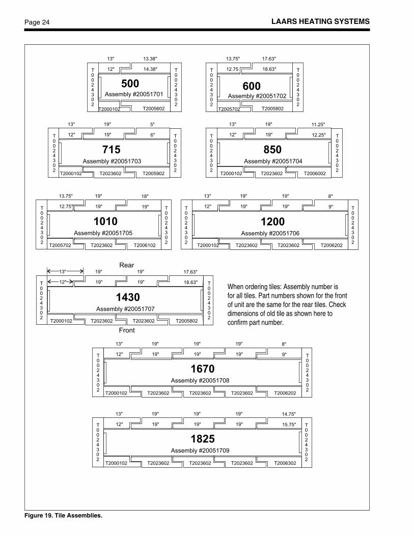
LAARS HEATING SYSTEMSPage 24
Figure 19. Tile Assemblies.
When ordering tiles: Assembly number isfor all tiles. Part numbers shown for the frontof unit are the same for the rear tiles. Checkdimensions of old tile as shown here toconfirm part number.
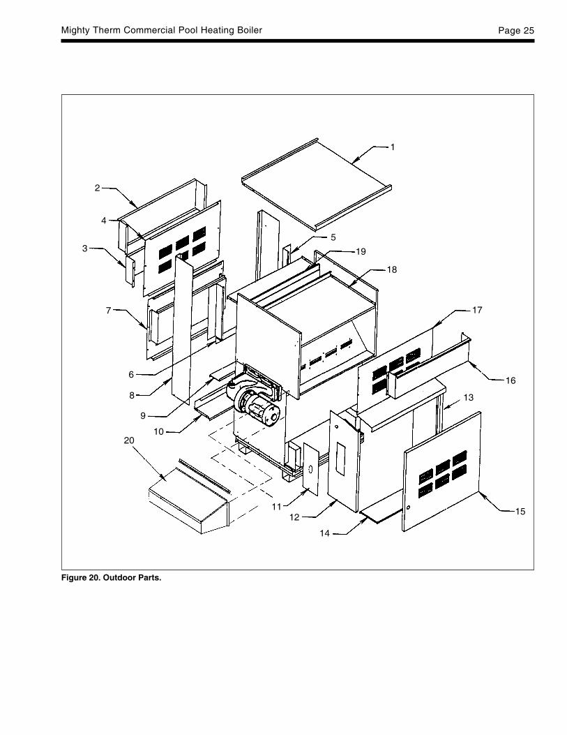
Mighty Therm Commercial Pool Heating Boiler Page 25
Figure 20. Outdoor Parts.
1
2
3
4
5
6
7
8
9
10
1112
14
15
16
17
18
19
13
20

LAARS HEATING SYSTEMSPage 26K
eyD
escr
ipti
on
Siz
eS
ize
Siz
eS
ize
Siz
eS
ize
Siz
eS
ize
Siz
eN
o50
060
071
585
010
1012
0014
3016
7018
25
31C
ontr
ol B
ox C
over
{O
utdo
or}
1063
0300
1063
0300
1063
0300
1063
0300
1063
0300
1063
0300
1063
0300
1063
0300
1063
0300
32N
on-C
ombu
stib
le B
ase/
Tile
1060
2301
1060
2302
1060
2303
1060
2304
1060
2305
1060
2306
1060
2307
1060
2308
1060
2309
Sup
port
Ass
embl
y {O
utdo
or}
3410
-Tub
e A
ssem
bly,
1066
5901
1066
5902
1066
5903
1066
5904
1066
5905
1066
5906
1066
5907
1066
5908
1066
5909
Cop
per
Tub
e/C
ast I
ron
Tub
s {O
utdo
or}
10-T
ube
Ass
embl
y,20
0011
0120
0011
0220
0011
0320
0011
0420
0011
0520
0011
0620
0011
0720
0011
0820
0011
09C
oppe
r T
ube/
Bro
nze
Tub
s {O
utdo
or}
10-T
ube
Ass
embl
y,20
0010
0120
0010
0220
0010
0320
0010
0420
0010
0520
0010
0620
0010
0720
0010
0820
0010
09C
U-N
I Tub
es/ C
ast I
ron
Tub
s {O
utdo
or}
10-T
ube
Ass
embl
y,10
6704
0110
6704
0210
6704
0310
6704
0410
6704
0510
6704
0610
6704
0710
6704
0810
6704
09C
U-N
I Tub
es/ B
ronz
e T
ubs
{Out
door
}35
Baf
fle, H
eat E
xcha
nger
Fro
nt/R
ear
2002
0101
2002
0102
2002
0103
2002
0104
2002
0105
2002
0106
2002
0107
2002
0108
2002
0109
{Out
door
}(2
)(2
)(2
)(2
)(2
)(2
)(2
)(2
)(2
)36
Baf
fle, H
eat E
xcha
nger
, 10-
Tub
e10
6677
0110
6677
0210
6677
0310
6677
0410
6677
0510
6677
0610
6677
0710
6677
0810
6677
09(7
)(1
4)(1
4)(1
4)(1
4)(2
8)(2
8)(2
8)(1
4)B
affle
, Hea
t Exc
hang
er, 1
0-T
ube
--
--
--
--
1066
7702
(14)
Ref
er T
o F
igu
re 2
1 F
or
Pla
cem
ent
1T
op P
anel
1066
0701
1066
0702
1066
0703
1066
0704
1066
0705
1066
0706
1066
0707
1066
0708
1066
0709
2R
ear
Win
dshi
eld
1065
8101
1065
8102
1065
8103
1065
8104
1065
8105
1065
8106
1065
8107
1065
8108
1065
8109
3U
pper
Rea
r Lo
uver
shi
eld
1065
7101
1065
7102
1065
7103
1065
7104
1065
7105
1065
7106
1065
7107
1065
7108
1065
7109
4U
pper
Rea
r P
anel
1065
8701
1065
8702
1065
8703
1065
8704
1065
8705
1065
8706
1065
8707
1065
8708
1065
8709
5G
ap C
losu
re-S
ide
1066
0200
1066
0200
1066
0200
1066
0200
1066
0200
1066
0200
1066
0200
1066
0200
1066
0200
(2)
(2)
(2)
(2)
(2)
(2)
(2)
(2)
(2)
6G
ap C
losu
re-M
iddl
e10
6601
0110
6601
0210
6601
0310
6601
0410
6601
0510
6601
0610
6601
0710
6601
0810
6601
097
Low
er R
ear
Pan
el A
ssem
bly
1066
0501
1066
0502
1066
0503
1066
0504
1066
0505
1066
0506
1066
0507
1066
0508
1066
0509
8R
ear
End
Pan
el L
eft a
nd R
ight
1065
7700
1065
7700
1065
7700
1065
7700
1065
7700
1065
7700
1065
7700
1065
7700
1065
7700
(2)
(2)
(2)
(2)
(2)
(2)
(2)
(2)
(2)
9Lo
wer
Rea
r S
hiel
d-In
ner
1065
9901
1065
9902
1065
9903
1065
9904
1065
9905
1065
9906
1065
9907
1065
9908
1065
9909
10R
ear
Bas
e E
xten
sion
1065
8501
1065
8502
1065
8503
1065
8504
1065
8505
1065
8506
1065
8507
1065
8508
1065
8509
11G
as T
rain
Inte
rfac
e P
late
2005
0200
2005
0200
2005
0200
2005
0200
2005
0200
2005
0200
2005
0200
2005
0200
2005
0200
12Le
ft F
ront
End
Pan
el10
6575
0110
6575
0110
6575
0110
6575
0110
6575
0110
6575
0110
6575
0110
6575
0110
6575
0113
Rig
ht F
ront
End
Pan
el10
6575
0210
6575
0210
6575
0210
6575
0210
6575
0210
6575
0210
6575
0210
6575
0210
6575
0214
Fro
nt B
ase
Ext
ensi
on10
6597
0110
6597
0210
6597
0310
6597
0410
6597
0510
6597
0610
6597
0710
6597
0810
6597
0915
Doo
r P
anel
Wel
dmen
t20
0504
0120
0504
0220
0504
0320
0504
0420
0504
0520
0504
0620
0504
0720
0504
0820
0504
09Le
ft D
oor
Pan
el W
eldm
ent
--
--
2010
0705
2010
0706
2010
0707
2010
0708
2010
0709
NO
TE
: Num
bers
in (
) re
pres
ent q
uant
ity r
equi
red
for
each
siz
e. Q
uant
ity is
one
oth
erw
ise.
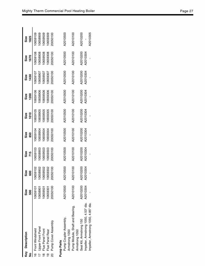
Mighty Therm Commercial Pool Heating Boiler Page 27
Key
Des
crip
tio
nS
ize
Siz
eS
ize
Siz
eS
ize
Siz
eS
ize
Siz
eS
ize
No
500
600
715
850
1010
1200
1430
1670
1825
16F
ront
Win
dshi
eld
1065
9101
1065
9102
1065
9103
1065
9104
1065
9105
1065
9106
1065
9107
1065
9108
1065
9109
17U
pper
Fro
nt P
anel
1065
8901
1065
8902
1065
8903
1065
8904
1065
8905
1065
8906
1065
8907
1065
8908
1065
8909
18F
lue
Pan
el F
ront
1065
9501
1065
9502
1065
9503
1065
9504
1065
9505
1065
9506
1065
9507
1065
9508
1065
9509
19F
lue
Pan
el R
ear
1065
9301
1065
9302
1065
9303
1065
9304
1065
9305
1065
9306
1065
9307
1065
9308
1065
9309
20P
ump
Cov
er A
ssem
bly
2005
0100
2005
0100
2005
0100
2005
0100
2005
0100
2005
0100
2005
0100
2005
0100
2005
0100
Pu
mp
Par
tsP
ump
Cou
pler
Ass
embl
y,A
2010
500
A20
1050
0A
2010
500
A20
1050
0A
2010
500
A20
1050
0A
2010
500
A20
1050
0A
2010
500
Arm
stro
ng 1
050
Pum
p M
odul
e, S
haft
and
Bea
ring,
A20
1010
0A
2010
100
A20
1010
0A
2010
100
A20
1010
0A
2010
100
A20
1010
0A
2010
100
A20
1010
0A
rmst
rong
105
0S
eal K
it, A
rmst
rong
150
A20
1020
0A
2010
200
A20
1020
0A
2010
200
A20
1020
0A
2010
200
A20
1020
0A
2010
200
A20
1020
0Im
pelle
r, A
rmst
rong
105
0, 4
.53"
dia
.A
2010
304
A20
1030
4A
2010
304
A20
1030
4A
2010
304
A20
1030
4A
2010
304
A20
1030
4-
Impe
ller,
Arm
stro
ng 1
050,
4.8
5" d
ia.
--
--
--
--
A20
1030
5

H00
6730
0S
Waterpik Technologies, Inc.6000 Condor Drive, Moorpark, CA 93021 • 805.529.2000 • FAX 805.529.593420 Industrial Way, Rochester, NH 03867 • 603.335.6300 • FAX 603.335.3355480 S. Service Road West, Oakville, Ontario, Canada L6K 2H4 • 905.844.8233 • FAX 905.844.2635www.laars.com Litho in U.S.A. © Laars Heating Systems 0310 Document 3006S