model 80e book - sypris electronics · model and serial number of your equipment, ... 2-10 keyboard...
TRANSCRIPT
Operating Instructions for
MODEL 80eDisk Recorder/Reproducer
TECHNICALMANUAL
Sypris Data Systems605 East Huntington DriveMonrovia, CA 91016
16831695April 2003


Sypris Data Systems605 East Huntington DriveMonrovia, CA 91016
16831695-001 BMarch 2003
Instructions For
Model 80eDisk Recorder/Reproducer
TECHNICALMANUAL

This page intentionally left blank.
Sypris Data Systems Inc.Customer Service Support
In U.S.A.: 1-800-937-9220International: 1-626-930-9444
6:00 a.m. – 6:00 p.m. (GMT)Monday – Friday
The Sypris technical support provides a broad range of product* support, including:• Service – On-site and Factory• Technical Support• Replacement Parts – Spares and Repair/Exchange• Service Contracts – Renewals and Adjustments• Consumable Supplies
On-Site ServiceSypris initiates, monitors, and follows up on all service calls. Sypris uses a nationwide staff of Sypris-authorized field engineers to ensure the fastest possible service regardless of geographical location.
To initiate a service call, contact Sypris at 1-800-937-9220 and give the customer service managerthe following information:
• Name• Site location• Equipment description by model number and serial number• Description of problem• Name, telephone, and email of primary contact person
A field engineer will return your call to confirm and estimated on-site arrival time.
Factory ServiceFactory service is available at the Sypris Data Systems corporate headquarters for products whichdo not require immediate on-site service. For information call 1-800-937-9220. A customer servicemanager can provide current diagnostic fees and labor rates for your equipment. You will also receiveinstructions on shipping your equipment to Sypris.
Specific cost estimates cannot be provided without a diagnostic evaluation to determine the conditionof your equipment. You must deliver or ship your equipment to Sypris for this evaluation, for whichyou will be billed a diagnostic charge. After the condition of your equipment is determined, a servicetechnician will contact you with a cost quote for the required service and an estimated completiondate.
*This includes products manufactured by Honeywell Test Instruments Division and Metrum-Datatape.
Technical SupportFactory trained technicians, experts on your specific equipment, are available to help you resolveequipment problems by telephone and email. Call Sypris at 1-800-937-9220 and ask for TechnicalSupport. The Customer service manager will ask for your name, telephone, email address, and themodel and serial number of your equipment, and then, direct your call to a technician who is highlyspecialized with your equipment. If the technician is not immediately available to assist you, yourcall will be returned in a timely manner.
Spare Parts and Repair/Exchange PartsCall 1-800-937-9220 when you need to order spare or repair/exchange parts. The Customer ServiceManager will direct your call to the appropriate parts specialist.
To Add/Delete Equipment on Service ContractPeriodically, it may be necessary to add or delete equipment to your on-site service contract. Pleaseuse one of the following methods to add or delete equipment:
• Phone your request to Sypris by calling 1-800-937-9220• Fax your request to 1-626-930-9482• Mail your request to Sypris Data Systems Inc.,
605 East Huntington Drive, Monrovia, CA 91016-3636• Email your request from the Sypris Data System Web site at
http://www.syprisdatasystems.com
To Renew/Change Service ContractNormally, the Customer Service Manager will send an annual renewal notice to your current billingaddress 90 days prior to the renewal date for the Service Contract for your equipment. This noticeincludes the following information:
• Company name and address• Contact name• Equipment description by model number and serial number• Annual service contract pricing
Sign and return the renewal notice and include a new purchase order if applicable. Return the noticein the enclosed envelope or mail to: Sypris Data Systems Inc., 605 East Huntington Drive,Monrovia, CA 91016-3636, Attn.: Contracts.Changes in coverage or equipment may be requested with the renewal. Sypris must receive yourchange request in writing 30 days prior to the renewal effective date. For contract renewal assistance,call 1-800-937-9220.

TABLE OF CONTENTS
Page
SECTION 1 – INTRODUCTION
1-1 GENERAL . . . . . . . . . . . . . . . . . . . . . . . . . . . . . . . . . . . . . . . . . . . . . . . . . . . . . . . . .1-1
1-2 DESCRIPTION . . . . . . . . . . . . . . . . . . . . . . . . . . . . . . . . . . . . . . . . . . . . . . . . . . . . .1-1
1-2.1 Physical Description. . . . . . . . . . . . . . . . . . . . . . . . . . . . . . . . . . . . . . . . . . . . . . . . . .1-2
1-2.2 Functional Description . . . . . . . . . . . . . . . . . . . . . . . . . . . . . . . . . . . . . . . . . . . . . . . .1-2
1-2.2.1 General . . . . . . . . . . . . . . . . . . . . . . . . . . . . . . . . . . . . . . . . . . . . . . . . . . . . . . . . . . . .1-2
1-2.2.2 Touchscreen Display . . . . . . . . . . . . . . . . . . . . . . . . . . . . . . . . . . . . . . . . . . . . . . . . .1-3
1-2.2.3 RAID Disk Array . . . . . . . . . . . . . . . . . . . . . . . . . . . . . . . . . . . . . . . . . . . . . . . . . . . .1-3
1-2.2.4 ARMOR Interfaces. . . . . . . . . . . . . . . . . . . . . . . . . . . . . . . . . . . . . . . . . . . . . . . . . . .1-3
1-2.2.4.1 Host . . . . . . . . . . . . . . . . . . . . . . . . . . . . . . . . . . . . . . . . . . . . . . . . . . . . . . . . . . . . . .1-3
1-2.2.4.2 Tape Data . . . . . . . . . . . . . . . . . . . . . . . . . . . . . . . . . . . . . . . . . . . . . . . . . . . . . . . . . .1-3
1-2.2.4.3 Tape Control . . . . . . . . . . . . . . . . . . . . . . . . . . . . . . . . . . . . . . . . . . . . . . . . . . . . . . . .1-3
1-2.2.5 Archival Drive/Distribution Interfaces. . . . . . . . . . . . . . . . . . . . . . . . . . . . . . . . . . . .1-3
1-3 OPERATION . . . . . . . . . . . . . . . . . . . . . . . . . . . . . . . . . . . . . . . . . . . . . . . . . . . . . . .1-4
1-3.1 Disk Recorder . . . . . . . . . . . . . . . . . . . . . . . . . . . . . . . . . . . . . . . . . . . . . . . . . . . . . . .1-4
1-3.2 Host PC. . . . . . . . . . . . . . . . . . . . . . . . . . . . . . . . . . . . . . . . . . . . . . . . . . . . . . . . . . . .1-5
1-3.3 Archival/Distribution Interface . . . . . . . . . . . . . . . . . . . . . . . . . . . . . . . . . . . . . . . . .1-5
1-4 MODEL CODE . . . . . . . . . . . . . . . . . . . . . . . . . . . . . . . . . . . . . . . . . . . . . . . . . . . . .1-5
1-5 ACCESSORIES SUPPLIED . . . . . . . . . . . . . . . . . . . . . . . . . . . . . . . . . . . . . . . . . . .1-5
1-6 SPECIFICATIONS. . . . . . . . . . . . . . . . . . . . . . . . . . . . . . . . . . . . . . . . . . . . . . . . . . .1-5
SECTION 2 – INSTALLATION
2-1 GENERAL . . . . . . . . . . . . . . . . . . . . . . . . . . . . . . . . . . . . . . . . . . . . . . . . . . . . . . . . .2-1
2-2 UNPACKING. . . . . . . . . . . . . . . . . . . . . . . . . . . . . . . . . . . . . . . . . . . . . . . . . . . . . . .2-1
2-2.1 Backup Media. . . . . . . . . . . . . . . . . . . . . . . . . . . . . . . . . . . . . . . . . . . . . . . . . . . . . . .2-1
2-3 CLAIMS. . . . . . . . . . . . . . . . . . . . . . . . . . . . . . . . . . . . . . . . . . . . . . . . . . . . . . . . . . .2-1
2-4 RACK MOUNTING . . . . . . . . . . . . . . . . . . . . . . . . . . . . . . . . . . . . . . . . . . . . . . . . .2-1
2-5 POWER CONNECTION . . . . . . . . . . . . . . . . . . . . . . . . . . . . . . . . . . . . . . . . . . . . . .2-2
2-5.1 Voltage Selection Switch (if present) . . . . . . . . . . . . . . . . . . . . . . . . . . . . . . . . . . . . .2-2
2-5.2 Power Cable . . . . . . . . . . . . . . . . . . . . . . . . . . . . . . . . . . . . . . . . . . . . . . . . . . . . . . . .2-2
2-6 INTERNAL CABLE CONNECTIONS – J1, J2, AND COM3. . . . . . . . . . . . . . . . .2-3
2-7 CONNECTIONS TO ARMOR – J3, J4, J9, AND DATA IN . . . . . . . . . . . . . . . . . .2-3
2-8 SCSI STORAGE DEVICE CONNECTION – J10 (OPTIONAL). . . . . . . . . . . . . . .2-4
2-9 VIDEO OUT – J13 (OPTIONAL) . . . . . . . . . . . . . . . . . . . . . . . . . . . . . . . . . . . . . . .2-4
Table of Contents i

TABLE OF CONTENTS (Continued)
Page
SECTION 2 – INSTALLATION (Continued)
2-10 KEYBOARD AND MOUSE (OPTIONAL) . . . . . . . . . . . . . . . . . . . . . . . . . . . . . . .2-5
2-11 NETWORK CONNECTION – J5 (OPTIONAL) . . . . . . . . . . . . . . . . . . . . . . . . . . .2-5
2-12 ARMOR-TO-USER’S DATA I/O EQUIPMENT CONNECTIONS. . . . . . . . . . . . .2-5
SECTION 3 – OPERATION
3-1 GENERAL . . . . . . . . . . . . . . . . . . . . . . . . . . . . . . . . . . . . . . . . . . . . . . . . . . . . . . . . .3-1
3-2 FUNCTIONAL ROLES. . . . . . . . . . . . . . . . . . . . . . . . . . . . . . . . . . . . . . . . . . . . . . .3-1
3-3 POWERING UP THE SYSTEM . . . . . . . . . . . . . . . . . . . . . . . . . . . . . . . . . . . . . . . .3-1
3-4 DISK SETUP . . . . . . . . . . . . . . . . . . . . . . . . . . . . . . . . . . . . . . . . . . . . . . . . . . . . . . .3-2
3-4.1 Record Storage Methods . . . . . . . . . . . . . . . . . . . . . . . . . . . . . . . . . . . . . . . . . . . . . .3-2
3-4.1.1 Single File. . . . . . . . . . . . . . . . . . . . . . . . . . . . . . . . . . . . . . . . . . . . . . . . . . . . . . . . . .3-2
3-4.1.2 Multiple Files . . . . . . . . . . . . . . . . . . . . . . . . . . . . . . . . . . . . . . . . . . . . . . . . . . . . . . .3-2
3-4.2 Playback File . . . . . . . . . . . . . . . . . . . . . . . . . . . . . . . . . . . . . . . . . . . . . . . . . . . . . . .3-3
3-4.3 Setting the Record Storage Method and Playback Filename . . . . . . . . . . . . . . . . . . .3-3
3-5 ARMOR CONTROL . . . . . . . . . . . . . . . . . . . . . . . . . . . . . . . . . . . . . . . . . . . . . . . . .3-4
3-6 RECORDING ARMOR DATA . . . . . . . . . . . . . . . . . . . . . . . . . . . . . . . . . . . . . . . . .3-5
3-7 PLAYING ARMOR DATA . . . . . . . . . . . . . . . . . . . . . . . . . . . . . . . . . . . . . . . . . . . .3-6
3-8 ARCHIVING DATA . . . . . . . . . . . . . . . . . . . . . . . . . . . . . . . . . . . . . . . . . . . . . . . . .3-7
3-8.1 Using the PBN Reader . . . . . . . . . . . . . . . . . . . . . . . . . . . . . . . . . . . . . . . . . . . . . . . .3-7
3-8.1.1 Single File Mode . . . . . . . . . . . . . . . . . . . . . . . . . . . . . . . . . . . . . . . . . . . . . . . . . . . .3-8
3-8.1.2 Multiple File Mode. . . . . . . . . . . . . . . . . . . . . . . . . . . . . . . . . . . . . . . . . . . . . . . . . . .3-8
3-8.2 Drive Identification . . . . . . . . . . . . . . . . . . . . . . . . . . . . . . . . . . . . . . . . . . . . . . . . . .3-9
3-8.3 DLT (Digital Linear Tape) Drive . . . . . . . . . . . . . . . . . . . . . . . . . . . . . . . . . . . . . . . .3-9
3-8.4 Compact Disk (CDR/RW) . . . . . . . . . . . . . . . . . . . . . . . . . . . . . . . . . . . . . . . . . . . . .3-10
3-8.5 DVD-RAM . . . . . . . . . . . . . . . . . . . . . . . . . . . . . . . . . . . . . . . . . . . . . . . . . . . . . . . . .3-10
3-8.6 Model 64 Tape Drive . . . . . . . . . . . . . . . . . . . . . . . . . . . . . . . . . . . . . . . . . . . . . . . . .3-10
3-9 NETWORK OPERATION. . . . . . . . . . . . . . . . . . . . . . . . . . . . . . . . . . . . . . . . . . . . .3-13
3-9.1 Network Setup . . . . . . . . . . . . . . . . . . . . . . . . . . . . . . . . . . . . . . . . . . . . . . . . . . . . . .3-13
3-9.2 Transmiing Data Files Over the Network. . . . . . . . . . . . . . . . . . . . . . . . . . . . . . . . . .3-13
3-10 POWERING DOWN THE SYSTEM . . . . . . . . . . . . . . . . . . . . . . . . . . . . . . . . . . . .3-14
Table of Contents ii
TABLE OF CONTENTS (Continued)
Page
SECTION 4 – MAINTENANCE
4-1 GENERAL . . . . . . . . . . . . . . . . . . . . . . . . . . . . . . . . . . . . . . . . . . . . . . . . . . . . . . . . .4-1
4-2 ROUTINE MAINTENANCE . . . . . . . . . . . . . . . . . . . . . . . . . . . . . . . . . . . . . . . . . .4-1
4-2.1 External Cleaning . . . . . . . . . . . . . . . . . . . . . . . . . . . . . . . . . . . . . . . . . . . . . . . . . . . .4-1
4-2.2 Cleaning the Touchscreen. . . . . . . . . . . . . . . . . . . . . . . . . . . . . . . . . . . . . . . . . . . . . .4-2
4-2.3 Packaging the Disk Recorder for Shipment . . . . . . . . . . . . . . . . . . . . . . . . . . . . . . . .4-2
4-3 CORRECTIVE MAINTENANCE. . . . . . . . . . . . . . . . . . . . . . . . . . . . . . . . . . . . . . .4-2
4-3.1 Reinstalling and Upgrading Software . . . . . . . . . . . . . . . . . . . . . . . . . . . . . . . . . . . .4-3
4-3.1.1 General . . . . . . . . . . . . . . . . . . . . . . . . . . . . . . . . . . . . . . . . . . . . . . . . . . . . . . . . . . . .4-3
4-3.1.2 Upgrading Software . . . . . . . . . . . . . . . . . . . . . . . . . . . . . . . . . . . . . . . . . . . . . . . . . .4-3
4-3.2 Installing Archival Drives in Front-panel Drive Bays . . . . . . . . . . . . . . . . . . . . . . . .4-3
Table of Contents iii
LIST OF ILLUSTRATIONS
Page
Figure 1-1. Model 80e Disk Recorder (typical) . . . . . . . . . . . . . . . . . . . . . . . . . . . . . . . . . . . . . .1-1
Figure 2-1. Power Cable Polarities . . . . . . . . . . . . . . . . . . . . . . . . . . . . . . . . . . . . . . . . . . . . . . . .2-2
Figure 2-2. Model 80e Rear Panel (typical) . . . . . . . . . . . . . . . . . . . . . . . . . . . . . . . . . . . . . . . . .2-3
Figure 2-3. Disk Recorder System Interconnect Diagram . . . . . . . . . . . . . . . . . . . . . . . . . . . . . .2-4
Figure 2-4. Model 80e Front Panel . . . . . . . . . . . . . . . . . . . . . . . . . . . . . . . . . . . . . . . . . . . . . . . .2-5
Figure 3-1. Disk Recorder Setup Screen (typical) . . . . . . . . . . . . . . . . . . . . . . . . . . . . . . . . . . . .3-3
Figure 3-2. ARMOR Primary Control Screen (typical) . . . . . . . . . . . . . . . . . . . . . . . . . . . . . . . .3-4
Figure 3-3. ARMOR Play Mode Setup Screen (typical) . . . . . . . . . . . . . . . . . . . . . . . . . . . . . . .3-5
Figure 3-4. PBN Reader – Single File Mode (typical) . . . . . . . . . . . . . . . . . . . . . . . . . . . . . . . . .3-8
Figure 3-5. PBN Reader – Multiple Files Mode (typical). . . . . . . . . . . . . . . . . . . . . . . . . . . . . . .3-8
Figure 3-6. System Utilities Window (typical) . . . . . . . . . . . . . . . . . . . . . . . . . . . . . . . . . . . . . . .3-9
Figure 3-7. PCI-V64 Software Screen (typical) . . . . . . . . . . . . . . . . . . . . . . . . . . . . . . . . . . . . . .3-11
Figure 4-1. Fan Exhaust Port and Air Inlet Holes. . . . . . . . . . . . . . . . . . . . . . . . . . . . . . . . . . . . .4-1
LIST OF TABLES
Table 1-1. Model Code Legend . . . . . . . . . . . . . . . . . . . . . . . . . . . . . . . . . . . . . . . . . . . . . . . . . .1-6
Table 1-2. Accessories Supplied . . . . . . . . . . . . . . . . . . . . . . . . . . . . . . . . . . . . . . . . . . . . . . . . .1-6
Table 1-3. Disk Recorder Specifications . . . . . . . . . . . . . . . . . . . . . . . . . . . . . . . . . . . . . . . . . . .1-6
Table 2-1. Disk Recorder Interconnect Cables . . . . . . . . . . . . . . . . . . . . . . . . . . . . . . . . . . . . . .2-4
Table of Contents iv
CAUTION
Installation of user-software may result insystem conflicts which can render theDisk Recorder unusable. Contact SyprisData Systems Technical Support to verifysoftware compatibility before installingany software on your Disk Recorder.
NOTEDo not install any software from mediaincluded with the Disk Recorder. Allrequired software is pre-installed, pre-configured, and fully tested before theDisk Recorder is shipped from the fac-tory. Software media is supplied forbackup purposes only.
Sypris Data Systems Technical Support1-800-937-9220
6:00 a.m. – 6:00 p.m. (GMT)Monday – Friday
NOTICE
The Model 80e disk recorder is a computer-based recording instrument. If any computer software pro-grams are installed that are not specifically authorized by Sypris Data Systems, they can interfere with the performance and functionality of the instrument and, at Sypris’ discretion, void the warranty.
Sypris Data Systems Technical Support1-800-937-9220
6:00 a.m. – 6:00 (GMT)Monday – Friday
WARRANTY
Sypris Data Systems (hereafter known as the Company) warrants, under its Repair/Exchange policy, all equipment purchased from and/or manufactured by it or bear-ing its nameplate to be free from defects in workmanship and material, under nor-mal use and service for 12 months as follows: (1) after built-in self-test, user diagnostic procedures, telephone service consulting, and procedures established by the Company have been followed, the Company may, at its option, direct Buyer to return, transportation prepaid, those parts of the equipment claimed to be defective to the Company’s designated service center, and (2) if found by the Company’s inspection to be defective in workmanship or material, at the Company’s option, it will be repaired or exchanged free of charge and returned-shipped lowest cost trans-portation prepaid. If inspection by the Company does not disclose any defect in workmanship or material, the Company’s then current service charges will apply. Only the warranty remaining on the original equipment will apply to the repaired or replaced equipment. During the warranty period, the Company may, at its option, provide on-site support and service. The applicable warranty period starts on the original date of shipment of the equipment from factory by the Company.
The foregoing warranty does not apply to contracts for repair, maintenance, or cali-bration. WITH EXCEPTION OF THE 12 MONTH WARRANTY SET FORTH ABOVE, SYPRIS DATA SYSTEMS MAKES NO EXPRESS WARRANTIES, NO WARRANTIES OF MERCHANTABILITY, AND NO WARRANTIES WHICH EXTEND BEYOND THE DESCRIPTION ON THE FACE HEREOF. In no event will Sypris Data Systems be responsible for any indirect, special or consequential damages including damages caused by delay in implementing the warranty, with respect to any claim by Buyer or any third party on account of or arising from this agreement or the use of any equipment, documentation, and services provided.
Sypris Data SystemsApril 2003

This page intentionally left blank.
SECTION 1
INTRODUCTION
1-1 GENERAL
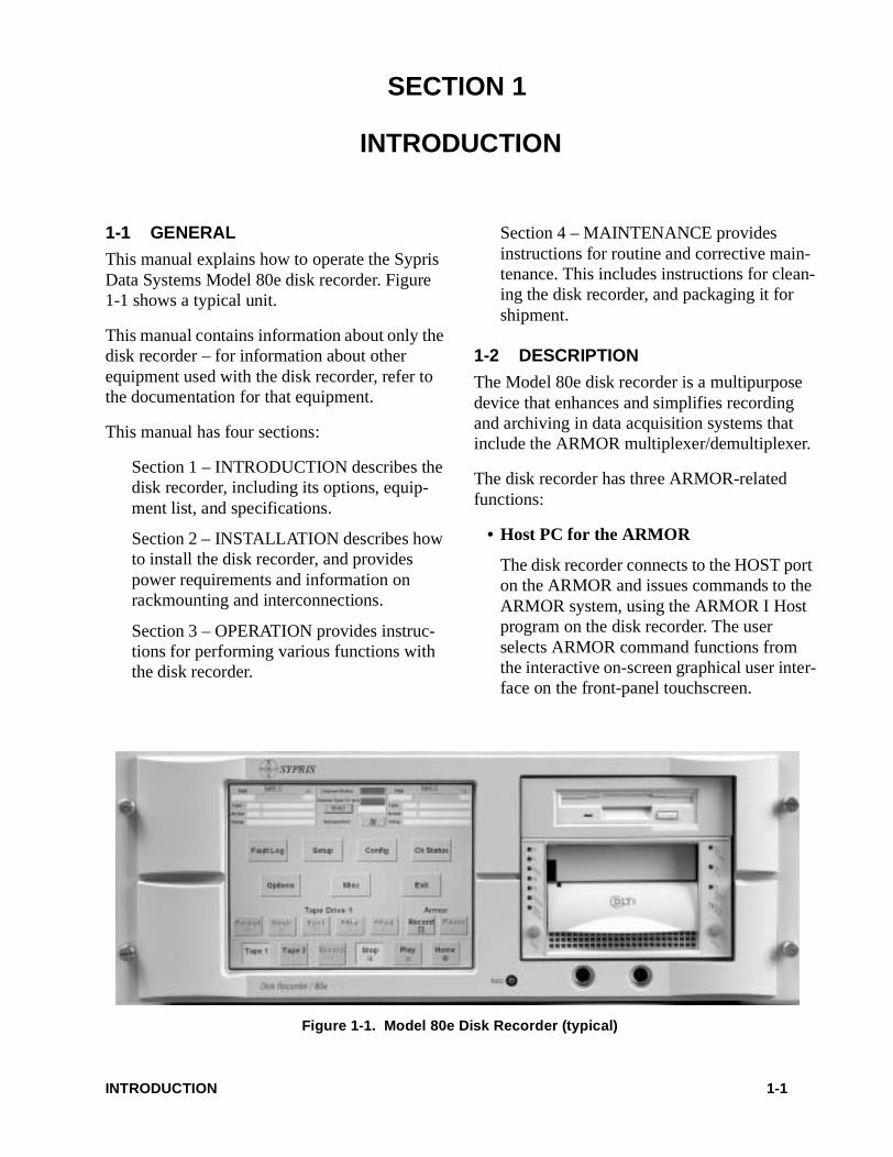
This manual explains how to operate the Sypris Data Systems Model 80e disk recorder. Figure 1-1 shows a typical unit.
This manual contains information about only the disk recorder – for information about other equipment used with the disk recorder, refer to the documentation for that equipment.
This manual has four sections:
Section 1 – INTRODUCTION describes the disk recorder, including its options, equip-ment list, and specifications.
Section 2 – INSTALLATION describes how to install the disk recorder, and provides power requirements and information on rackmounting and interconnections.
Section 3 – OPERATION provides instruc-tions for performing various functions with the disk recorder.
Section 4 – MAINTENANCE provides instructions for routine and corrective main-tenance. This includes instructions for clean-ing the disk recorder, and packaging it for shipment.
1-2 DESCRIPTION
The Model 80e disk recorder is a multipurpose device that enhances and simplifies recording and archiving in data acquisition systems that include the ARMOR multiplexer/demultiplexer.
The disk recorder has three ARMOR-related functions:
• Host PC for the ARMOR
The disk recorder connects to the HOST port on the ARMOR and issues commands to the ARMOR system, using the ARMOR I Host program on the disk recorder. The user selects ARMOR command functions from the interactive on-screen graphical user inter-face on the front-panel touchscreen.
Figure 1-1. Model 80e Disk Recorder (typical)
INTRODUCTION 1-1

• Data Recorder
The disk recorder connects to the DATA IN, DATA OUT, and TAPE CONTROL ports on the ARMOR and functions as a data recorder and reproducer. It writes the multiplexed data stream from the ARMOR to its internal disk-array subsystem. The disk array uses level-0 Redundant Array of Independent Disks (RAID) technology, which enables the disk recorder to store data at rates of up to 128 megabits per second (streaming) and capacities of 54 to 288 Gigabytes, depending upon the disk array configuration installed.
• Archival Drive/Distribution Interfaces
Data from the RAID can be copied to an optional storage device or to a network for archival storage or distribution.
The disk recorder has three front-panel half-height drive bays for optional removable-media storage devices, such as DLT, DDS-4, CD-R/RW, or DVD-RAM. A rear-panel SCSI bus connector can be attached to an external SCSI storage device such as a DTF-2 tape drive. Each disk recorder is supplied with factory-installed copy-utility programs that are compatible with the data formats of all supported storage devices.
Additionally, data files can be copied from the internal disk array of a disk recorder to remote equipment for analysis or archiving, using standard Ethernet.
1-2.1 Physical Description
The disk recorder is a highly specialized rack-mounted data recorder and storage system that fits in a 19-inch wide RETMA equipment rack that is at least 24 inches deep. The disk recorder requires seven inches of vertical rack space, and uses industry-standard slides.
The front panel contains the touchscreen display, connectors for an optional keyboard and mouse, and three half-height drive bays. A 3.5-inch dis-kette drive can be installed in one of the bays, rather than on the rear panel.
The rear panel contains a 3.5-inch diskette drive (if not mounted in a front-panel bay), the power input, and the following connectors:
1-2.2 Functional Description
The disk recorder appears to the ARMOR as a tape drive, to which the ARMOR can record and play back data. Additionally, the disk recorder appears to the ARMOR as the host computer from which the ARMOR receives its setup and operational commands.
1-2.2.1 General
The disk recorder is built around a Pentium®-class, Windows NT® workstation (complete with system disk, RAM, and floppy diskette drive), with a disk array subsystem consisting of multiple hard drives and a RAID controller.
The workstation has a flat-panel touchscreen display, supported by a VGA/flat-screen video adapter, touchscreen controller, and display-panel inverter.
J3–HOST(COM2)
Connects to the HOST PC connector on ARMOR
J4–CTRL(COM1)
Connects to the TAPE 1 CONTROL connector onARMOR
COM3Long touchscreen cable be-low J9 and J10, with DB-9 connector
J5–NET Connects to a 10BaseT/100BaseT Ethernet network
J6 Not used
J7 VGA
Connects to front-panel flatscreen display via the cable out of the back panel, OR to an external monitor via the cable on the monitor.
J8–PAR Not used
DATA IN Connects to the DATA 1 OUT connector on ARMOR
J9 DATA OUT Connects to the DATA 1 IN connector on ARMOR
J10 SCSI Connects to an optional ex-ternal SCSI storage device
J11 Connect to optional external hard disks for extended RAID
INTRODUCTION 1-2
To interface with the ARMOR for data and con-trol, the disk recorder has on-board RS-232 serial ports and a parallel data interface.
The workstation also has on-board IDE and SCSI buses to support the various optional archi-val storage devices that can be installed in the front-panel bays.
1-2.2.2 Touchscreen Display
The front-panel touchscreen is mounted in front of a flat-panel display. The touchscreen control-ler interfaces with the workstation board via COM3. (Touchscreen inputs emulate mouse clicks.) The flat-panel display has a controller card mounted behind it.
When the cable on the rear panel above J7 is connected to J7, the controller drives the front-panel display. When that cable is disconnected, the cable of an external monitor can be con-nected to J7. The front-panel touchscreen is then disabled, and the external monitor is active.
When an external monitor is not used, command screens are displayed on the front-panel display. The command screens work like a control panel, with touch buttons and status displays for com-plete local control of the disk recorder/ARMOR system.
To input commands or select available options, lightly touch a fingertip to a “pushbutton” or active selection field on the touchscreen.
If an external monitor is used, a mouse has to be connected to front of the disk recorder and used to operate the control software.
1-2.2.3 RAID Disk Array
The internal disk array is configured as a RAID level-0 striped disk array. The RAID controller breaks data down into blocks and writes each block to a separate disk drive. This process of striping data blocks across multiple drives in a continuous sequence allows greater I/O perfor-mance than single-disk systems.
The configurations of disk array subsystems supplied with factory-configured disk recorders are identified by the system model code shown in Table 1-1. All disk array subsystems, regard-less of the number or size of drives in the array, are RAID level-0 and can support write/read data transfer rates of up to 128 megabits per sec-ond. Data capacity, however, depends on on both the number and size of the drives in the RAID. The total RAID capacity is simply the sum of the capacities of its individual drives.
1-2.2.4 ARMOR Interfaces
The disk recorder connects to the ARMOR via four interfaces: HOST, DATA IN, DATA OUT, and TAPE CONTROL. These interfaces use emulation software and firmware that let the disk recorder appear as a tape drive to the ARMOR.
1-2.2.4.1 Host
The Host interface lets the disk recorder control the ARMOR. ARMOR setup and control opera-tions are accomplished via the ARMOR I HOST software in the disk recorder, and are linked with the controller module in the ARMOR through the J3 - HOST (COM2) port of the disk recorder.
1-2.2.4.2 Tape Data
The Data interface is on the High Speed Emula-tor, PCI-D240 parallel interface card in one of the PCI slots of the disk recorder.
1-2.2.4.3 Tape Control
The J4 - CTRL (COM1) port of the disk recorder connects to the TAPE 1 CONTROL connector on the ARMOR. This interface supports all rele-vant tape drive control signal lines and proto-cols.
1-2.2.5 Archival Drive/Distribution Interfaces
Data can be copied from the disk array to optional archival drives, such as DLT, DDS-4, CD-R/RW, DVD-RAM, Model 64, etc., using various media for archiving and distribution pur-poses.
INTRODUCTION 1-3
Front-panel devices connect to the system board via on-board IDE, Ultra-wide SCSI, and/or Ultra2/LVD SCSI interface connectors. For fac-tory-installed archival drives, device drivers are factory-installed and configured.
Each disk recorder, regardless of the drive con-figuration, also has a rear-panel Ultra-wide SCSI port.
All disk recorders provide network connectivity and can transmit data files, copied from the internal RAID, to remote equipment over a 10baseT/100baseT Ethernet network, using TCP/IP protocols (Ping, FTP, and Telnet).
NOTE
Detailed instructions for using the ARMOR Setup and Control Software are provided in the ARMOR technical manual,
Operating Instructions For ARMOR Multiplexer/Demulti-plexer. You should be familiar with Sections 5 and 6 of that manual before attempting to operate the disk recorder.
1-3 OPERATION
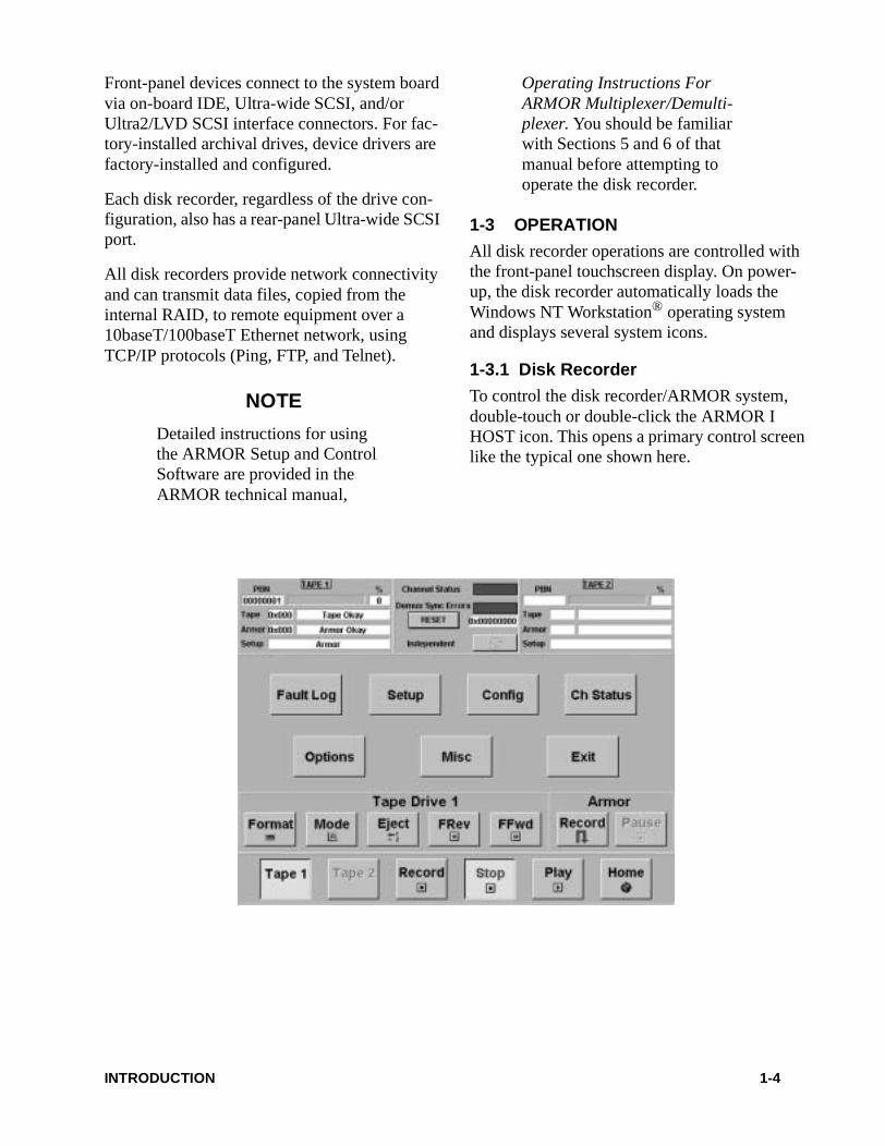
All disk recorder operations are controlled with the front-panel touchscreen display. On power-up, the disk recorder automatically loads the Windows NT Workstation® operating system and displays several system icons.
1-3.1 Disk Recorder
To control the disk recorder/ARMOR system, double-touch or double-click the ARMOR I HOST icon. This opens a primary control screen like the typical one shown here.
INTRODUCTION 1-4
Disk recorder operations such as Record, Stop, Read Setup From Tape, Play from PBN, Play from IRIG Time, Format, FFWD, FREV, and tape monitor, will now function identically to those of a tape drive (TAPE 1) that is under ARMOR control.
1-3.2 Host PC
When you power up the disk recorder and select the ARMOR I HOST icon on the touchscreen, the disk recorder will run the ARMOR software and become the ARMOR system controller device (Host PC). All ARMOR functions are accessible via the touchscreen when the disk recorder functions as the Host PC.
1-3.3 Archival/Distribution Interface
The disk recorder can be used to copy recorded data from the internal disk array to optional stor-age drives. Factory-configured disk recorders are available with various types of accessible storage drives. Drives are identified by logical drive IDs; this simplifies the transfer of data files from the disk array to a selected storage drive.
The various drives in the disk recorder are assigned the following drive letters:
A: 3.5-inch diskette drive (rear panel)C: NT/system driveD: User drive (partition on C:)E: RAID disk arrayF: DVD-RAM Drive (optional)G: CD-ROM Drive (optional)H: Additional user drive (partition on C:)
Additionally, the disk recorder can copy data from the internal RAID to an external SCSI stor-age device through the rear-panel SCSI port.
The disk recorder can also transmit data files copied from its internal RAID to remote equip-ment via its Ethernet port, using TCP/IP proto-cols (Ping, FTP, and Telnet).
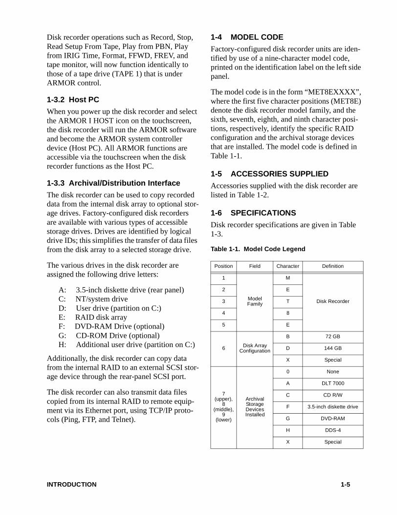
1-4 MODEL CODE
Factory-configured disk recorder units are iden-tified by use of a nine-character model code, printed on the identification label on the left side panel.
The model code is in the form “MET8EXXXX”, where the first five character positions (MET8E) denote the disk recorder model family, and the sixth, seventh, eighth, and ninth character posi-tions, respectively, identify the specific RAID configuration and the archival storage devices that are installed. The model code is defined in Table 1-1.
1-5 ACCESSORIES SUPPLIED
Accessories supplied with the disk recorder are listed in Table 1-2.
1-6 SPECIFICATIONS
Disk recorder specifications are given in Table 1-3.
Table 1-1. Model Code Legend
Position Field Character Definition
1
ModelFamily
M
Disk Recorder
2 E
3 T
4 8
5 E
6 Disk ArrayConfiguration
B 72 GB
D 144 GB
X Special
7 (upper),
8 (middle),
9 (lower)
ArchivalStorageDevicesInstalled
0 None
A DLT 7000
C CD R/W
F 3.5-inch diskette drive
G DVD-RAM
H DDS-4
X Special
INTRODUCTION 1-5
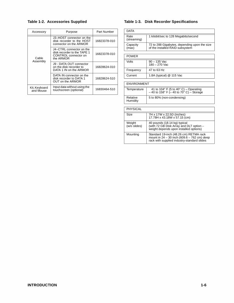
Table 1-2. Accessories Supplied Table 1-3. Disk Recorder Specifications
Accessory Purpose Part Number
CableAssembly
J3–HOST connector on thedisk recorder to the HOSTconnector on the ARMOR
16823378-010
J4–CTRL connector on the disk recorder to the TAPE 1 CONTROL connector on the ARMOR
16823378-010
J9 - DATA OUT connector on the disk recorder to DATA 1 IN on the ARMOR
16828624-010
DATA IN connector on the disk recorder to DATA 1 OUT on the ARMOR
16828624-510
Kit, Keyboard and Mouse
Input data without using the touchscreen (optional) 16830464-510
DATA
Rate(streaming)
1 kilobit/sec to 128 Megabits/second
Capacity(max)
72 to 288 Gigabytes, depending upon the size of the installed RAID subsystem
POWER
Volts 90 – 135 Vac180 – 270 Vac
Frequency 47 to 63 Hz
Current 1.8A (typical) @ 115 Vac
ENVIRONMENT
Temperature 41 to 104° F (5 to 40° C) – Operating– 40 to 158° F (– 40 to 70° C) – Storage
RelativeHumidity
5 to 80% (non-condensing)
PHYSICAL
Size 7H x 17W x 22.5D (inches)17.78H x 43.18W x 57.15 (cm)
Weight(w/o slides)
40 pounds (18.14 kg) typical(with 72 GB Disk Array and DLT option – weight depends upon installed options)
Mounting Standard 19-inch (48.26 cm) RETMA rack mount in 24 – 30 inch (609.6 – 762 cm) deep rack with supplied industry-standard slides
INTRODUCTION 1-6
ESDS DEVICE HANDLING 1 of 1
ESDS DEVICE HANDLING
CAUTIONThis unit contains devices subjectto damage from electrostatic dis-charge (ESD). Handle electro-static discharge sensitive (ESDS)devices in accordance with thefollowing precautions andinstructions. Refer to DOD-HDBK-263 and DOD-STD-1686for additional ESD information.
1. ESDS components and circuit cards are shipped in special static dissipative ship-ping containers. Ensure that all required precautions are taken before opening the containers. Retain the containers for use when shipping ESD components. All static dissipative containers are identified with a warning label alerting the handler that the contents are ESD sensitive.
2. Because most Sypris Data Systems circuit cards contain ESDS components, all cir-cuit cards should be treated as being ESD sensitive. Individual components are not generally identified as being ESDS, except in packaging.
3. ESDS components should only be handled under the following conditions:
a. WHEN HANDLING ESDS ASSEM-BLIES OR DEVICES, THE HAN-DLER MUST WEAR A STATIC CONTROL WRIST STRAP CON-NECTED TO HIS OR HER SKIN.
The wrist strap must then be con-nected, through a 1 megohm resistor, to a static dissipative table top or to the equipment chassis ground. (NOTE: Most wrist straps have the 1 megohm resistor built in.) The static dissipative table top must be connected to ground through a 1 megohm resistor.
b. Handle ESDS components by the case or body whenever possible, and mini-mize touching of the leads.
c. Avoid the use of air blasts or aerosol sprays on ESDS circuit cards or com-ponents.
d. Pack and unpack ESDS components and devices only in static-free environ-ments on a static dissipative table top. The handler must wear a wrist strap during packing or unpacking.
e. Keep all common plastics and clothing away from ESDS devices.
f. All soldering irons, test equipment, and equipment chassis must be grounded. Grounded power cords must be plugged in, even if the equipment is turned off.
g. Solder suckers must be of the antistatic type.
h. Brushes must be of natural bristle.
4. Ensure that all ESDS devices are properly packaged in static dissipative coverings when in storage or transit.

This page intentionally left blank.
SECTION 2
INSTALLATION
2-1 GENERAL
This section explains how to install and set up the Model 80e disk recorder. It only contains information about the disk recorder – for infor-mation about other equipment used with the disk recorder, refer to the documentation for that equipment.
CAUTION
This equipment contains ESDS devices. You must follow the ESDS device-handling proce-dures explained in the ESDS DEVICE HANDLING informa-tion at the front of this manual.
CAUTION
The disk recorder contains no user-serviceable components. All internal components are prop-erly configured prior to shipment from the factory. To avoid dam-aging the disk recorder, do not remove covers or disturb any internal switch or jumper set-tings.
CAUTION
To avoid damaging equipment, shut down Windows NT and turn power OFF before connecting or disconnecting any cables.
2-2 UNPACKING
Removing the disk recorder and associated com-ponents and accessories from the shipping car-ton requires no special instructions, except to exercise normal care.
2-2.1 Backup Media
The disk recorder is shipped with manufactur-ers’ documentation packages and software media that support devices and application pro-grams installed in the disk recorder. Store these media as backup copies. All applicable soft-ware on these media has been installed and con-figured in the disk recorder at the factory, and these media will not be required for routine operations.
Retain the user instructions for the storage drive (DLT, CDR/RW, DVD-RAM, if supplied) for reference when operating the disk recorder.
NOTE
Keep the shipping carton and packing materials for reshipping the disk recorder.
2-3 CLAIMS
After unpacking, carefully inspect the disk recorder and associated components for shipping damage. If damage is found, immediately notify the carrier, submit a claim, and notify your Sypris Data Systems representative.
2-4 RACK MOUNTING
The disk recorder is designed to be installed in standard 19-inch RETMA racks on extendable slide assemblies. The slide assemblies supplied with the disk recorder can be used with racks
INSTALLATION 2-1
with depths of 24, 26, 28 and 30 inches. How-ever, to ensure adequate cable clearance, a 24-inch deep rack may be used only in an open-back configuration unless right-angle cables are used.
NOTE
The rear of the disk recorder should be accessible while installed in the rack to ease cable connections and provide access to the rear-mounted diskette drive.
When mounting the disk recorder, refer to the instructions supplied with the rack-mount slide kit for detailed step-by-step installation instruc-tions. Installation of the disk recorder is identical to that for the Model 64, Buffered VLDS, and VLDS, except for the following:
Be sure to use the bottom set of holes in the movable slide to attach the slide to the sides of the disk recorder.
2-5 POWER CONNECTION
2-5.1 Voltage Selection Switch (if present)
The disk recorder may be operated from 115 Vac or 230 Vac. Before you connect the power cord to the disk recorder, make sure the voltage selec-tion switch is set for the local facility power. See Figure 2-2.
2-5.2 Power Cable
The power switch is on the rear of the disk recorder and is not accessible when the disk recorder is mounted in a rack. To simplify turn-ing power on or off, the disk recorder power cable should be connected to a switched facility power source; preferably the same source that provides power to the ARMOR, Model 64, and any other devices connected to the disk recorder.
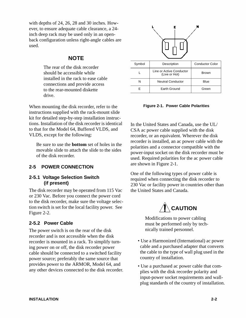
In the United States and Canada, use the UL/CSA ac power cable supplied with the disk recorder, or an equivalent. Wherever the disk recorder is installed, an ac power cable with the polarities and a connector compatible with the power-input socket on the disk recorder must be used. Required polarities for the ac power cable are shown in Figure 2-1.
One of the following types of power cable is required when connecting the disk recorder to 230 Vac or facility power in countries other than the United States and Canada.
CAUTION
Modifications to power cabling must be performed only by tech-nically trained personnel.
• Use a Harmonized (International) ac power cable and a purchased adapter that converts the cable to the type of wall plug used in the country of installation.
• Use a purchased ac power cable that com-plies with the disk recorder polarity and input-power socket requirements and wall-plug standards of the country of installation.
Figure 2-1. Power Cable Polarities
Symbol Description Conductor Color
L Line or Active Conductor(Live or Hot) Brown
N Neutral Conductor Blue
E Earth Ground Green
INSTALLATION 2-2
• In countries requiring IEC 950 compliance, use only a purchased 230V rated IEC 950-approved ac power cable that meets the disk recorder polarity and input-power socket requirements.
2-6 INTERNAL CABLE CONNECTIONS – J1, J2, AND COM3
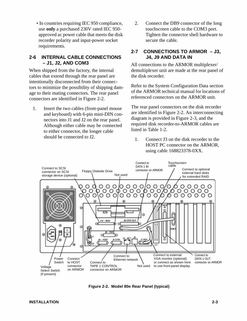
When shipped from the factory, the internal cables that extend through the rear panel are intentionally disconnected from their connec-tors to minimize the possibility of shipping dam-age to their mating connectors. The rear panel connectors are identified in Figure 2-2.
1. Insert the two cables (front-panel mouse and keyboard) with 6-pin mini-DIN con-nectors into J1 and J2 on the rear panel. Although either cable may be connected to either connector, the longer cable should be connected to J2.
2. Connect the DB9 connector of the long touchscreen cable to the COM3 port. Tighten the connector shell hardware to secure the cable.
2-7 CONNECTIONS TO ARMOR – J3, J4, J9 AND DATA IN
All connections to the ARMOR multiplexer/demultiplexer unit are made at the rear panel of the disk recorder.
Refer to the System Configuration Data section of the ARMOR technical manual for locations of referenced connectors on the ARMOR unit.
The rear panel connectors on the disk recorder are identified in Figure 2-2. An interconnecting diagram is provided in Figure 2-3, and the required disk recorder-to-ARMOR cables are listed in Table 1-2.
1. Connect J3 on the disk recorder to the HOST PC connector on the ARMOR, using cable 168823378-0XX.
Connect toDATA 1 OUTconnector on ARMORConnect to
TAPE 1 CONTROLconnector on ARMOR
Connectto HOST connectoron ARMOR
Connect to
Not used
Floppy Diskette Drive
PowerSwitch
VoltageSelect Switch
Figure 2-2. Model 80e Rear Panel (typical)
Connect to external VGA monitor (optional)
Not used
Ethernet network
Connect to SCSIconnector on SCSI storage device (optional)
Connect to optional external hard disksfor extended RAID
or connect as shown hereto use front-panel display
Touchscreen cable
Connect toDATA 1 INconnector on ARMOR
(if present)
INSTALLATION 2-3

2. Connect J4 on the disk recorder to the TAPE 1 CONTROL connector on the ARMOR, using cable 168823378-0XX.
3. Connect J9 on the disk recorder to the DATA 1 IN connector on the ARMOR, using cable 16828624-5XX.
4. Connect the DATA IN connector on the disk recorder to the DATA 1 OUT con-nector on the ARMOR, using cable 16828624-5XX.
2-8 SCSI STORAGE DEVICE CONNECTION – J10 (OPTIONAL)
Data stored in the disk recorder may be trans-ferred to a SCSI storage device, such as a SCSI-configured DTF-2 tape drive (or equivalent) for archiving and distribution purposes. Refer to Figure 2-3 during the following steps.
1. Connect J10 on the disk recorder to one of the SCSI connectors on the SCSI stor-age device, using the cable supplied with the device.
2. Connect the SCSI bus terminator (sup-plied with the storage device) to the other SCSI connector on the SCSI storage device.
2-9 VIDEO OUT – J7 (OPTIONAL)
The disk recorder supports an optional, user-sup-plied VGA monitor. The monitor cable connects to J7 on the rear of the disk recorder. The front-panel display is disabled when an external moni-tor is used.
2-10 KEYBOARD AND MOUSE (OPTIONAL)
The disk recorder can be operated by means of the external keyboard and mouse when it is not possible nor desirable to use the built-in touch-
Figure 2-3. Disk Recorder System Interconnect Diagram
INSTALLATION 2-4
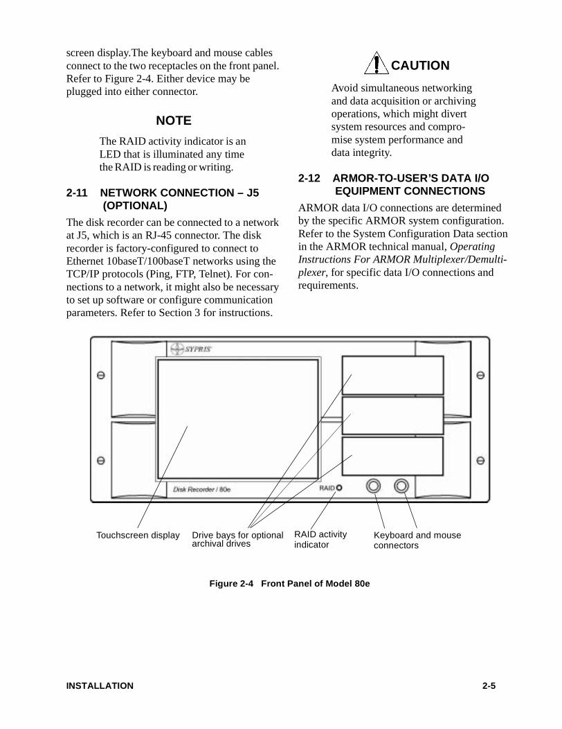
screen display.The keyboard and mouse cables connect to the two receptacles on the front panel. Refer to Figure 2-4. Either device may be plugged into either connector.
NOTE
The RAID activity indicator is an LED that is illuminated any time the RAID is reading or writing.
2-11 NETWORK CONNECTION – J5 (OPTIONAL)
The disk recorder can be connected to a network at J5, which is an RJ-45 connector. The disk recorder is factory-configured to connect to Ethernet 10baseT/100baseT networks using the TCP/IP protocols (Ping, FTP, Telnet). For con-nections to a network, it might also be necessary to set up software or configure communication parameters. Refer to Section 3 for instructions.
CAUTION
Avoid simultaneous networking and data acquisition or archiving operations, which might divert system resources and compro-mise system performance and data integrity.
2-12 ARMOR-TO-USER’S DATA I/O EQUIPMENT CONNECTIONS
ARMOR data I/O connections are determined by the specific ARMOR system configuration. Refer to the System Configuration Data section in the ARMOR technical manual, Operating Instructions For ARMOR Multiplexer/Demulti-plexer, for specific data I/O connections and requirements.
Touchscreen display Drive bays for optional Keyboard and mouse archival drives connectors
RAID activity indicator
Figure 2-4 Front Panel of Model 80e
INSTALLATION 2-5

SECTION 3
OPERATION
3-1 GENERAL
This section provides operating instructions for the Sypris Data Systems Model 80e Disk Recorder. Only information about the disk recorder is provided. Operating information for the ARMOR Multiplexer/Demultiplexer and Model 64 tape drive is provided in the appropri-ate documentation for those systems.
NOTE
It is assumed that the user is familiar with ARMOR opera-tions. References are made to various ARMOR operations that relate to the disk recorder, but the actual operations are not described here. The ARMOR technical manual, Operating Instructions for ARMOR Multi-plexer/Demultiplexer, should be available for reference.
This section assumes that the disk recorder is installed and connected to the ARMOR as described in Section 2 of this manual. It is also assumed that the ARMOR is connected to the user’s I/O equipment as specified by the System Configuration Data contained in Appendix A of the technical manual for your particular ARMOR.
3-2 FUNCTIONAL ROLES
The disk recorder has three functional roles:
• The primary role of the disk recorder is to emulate a tape drive. It can record multi-plexed data that is output from the ARMOR, store it in the disk recorder RAID, and play
the recorded data back from the RAID to the ARMOR for output to the user’s I/O equip-ment as demultiplexed data. The disk recorder can be configured to store data in the RAID as one continuous file or as con-secutively numbered individual files.
• The disk recorder acts as the Host PC for the ARMOR, so you can control the ARMOR unit with the built-in computer and front-panel touchscreen of the disk recorder. The ARMOR I Host software that controls the ARMOR resides on the system disk of the disk recorder and is executed by the built-in computer. The user interface of this software is the front panel touchscreen.
• The disk recorder functions as an archival drive/distribution interface, allowing data to be copied from the disk recorder RAID to various optional internal and external storage devices, or to be transmitted to remote equip-ment through standard network connections.
3-3 POWERING UP THE SYSTEM
NOTE
For convenience, the disk recorder, ARMOR, and other sys-tem components may be con-nected to a common, switched power source.
If the system has a common switched power source, begin by switching system power on. If the system has no common switched power source, apply power to the disk recorder first, and then to the ARMOR.
OPERATION 3-1
NOTE
The Windows NT® operating system may take from two to four minutes to complete the boot pro-cess. No error messages should be displayed during a normal boot. If you encounter an error message during boot, use the Event Viewer (Start > Programs > Admin Tools > Event Viewer) to look for the most recent red-flag entry to determine the cause of the error message. If the problem cannot be resolved, contact Syp-ris Data Systems technical sup-port services.
Additionally, the operating sys-tem may also request user input during the boot process. Ignore these requests and allow the boot to proceed on its own.
Upon power-up, the disk recorder will automati-cally load the Windows NT Workstation® oper-ating system and display the Windows desktop on the front-panel touchscreen display.
3-4 DISK SETUP
The Disk Setup program is used to establish the Record Storage Method (how ARMOR record data is stored in the disk recorder RAID) before beginning recording. The Disk Setup program can also be used to specify the playback file-name before beginning playback.
3-4.1 Record Storage Methods
Two record storage methods are possible: single file and multiple files. The record storage method affects the record operation only, so the Play and Format commands are not affected by your choice of the single-file or multiple-files method.
3-4.1.1 Single File
In the single-file method, ARMOR data is writ-ten to the RAID as one continuous file with the filename File-00-.dat. Each time the record com-mand is issued, the new record data is appended to the existing file (at end-of-data) in the RAID. Also, each time the record command is issued, the filename File-00-.dat is set as the default playback filename, so that when the disk recorder later receives a command to play, data is played back from that file, File-00-.dat.
Consequently, if the single-file method was used to store ARMOR data in the RAID, the data can then be copied to an archival device only as a single file. With the single-file method, specific recording sessions cannot be individually cop-ied.
The starting PBN of a recording session is the PBN offset into the data file where each record session begins. In the single-file storage method, the disk recorder logs the starting PBN for each recording session. You can retrieve the ARMOR setup information for a specific recording ses-sion when using the ARMOR Read Setup From Tape feature, even though the data itself for that specific session cannot be copied independently. The starting PBN for each recording session can be viewed with the disk recorder PBN Reader. Figure 3-4 shows a typical single-file PBN Reader display.
3-4.1.2 Multiple Files
In the multiple-files method, individual record-ing sessions are stored in the RAID as individual data files, which are automatically assigned sequential filenames of File-01-.dat through File-99-.dat. Each time a record command is issued, a new file is opened and data is written to the new file. Also, each time the record com-mand is issued, the new filename is set as the default playback filename, so when the disk recorder later receives a play command, data is played back from the last file recorded (the new file).
OPERATION 3-2
Because the multiple-files method stores each data file in the RAID as an independent entity with its own unique filename, a specific record-ing session can be copied to an archival record-ing device.
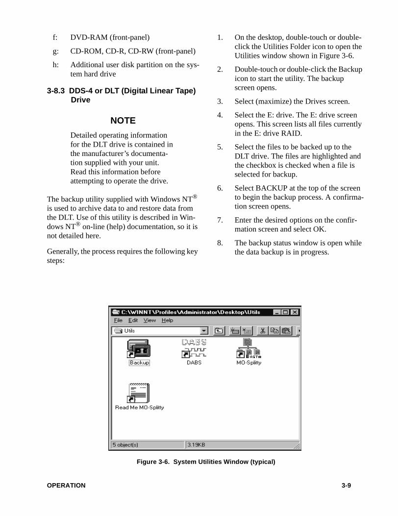
The disk recorder logs the starting PBN (the PBN offset into the data file where a record ses-sion begins) for each recording session. In the multiple-files storage method, where each record session begins at the beginning of the data file, the starting PBN is always 1. The filenames for each recording session can be viewed on the disk recorder display with the PBN Reader. Figure 3-5 shows a typical PBN Reader display for data recorded with the multiple-files method.
3-4.2 Playback File
Each time the disk recorder receives a command to record, it sets the default playback filename to the name of the current record data file. In the single-file storage method, the filename is always File-00-.dat. In the multiple-files storage method, the filename is File-nn-.dat, where nn is the recording session number from 1 to 99. In normal operation, therefore, you do not have to set the playback filename. However, before
commanding the disk recorder to play, you may change the playback filename by using the Disk Setup program. If you modify the playback file-name, the new name remains until the next recording session begins.
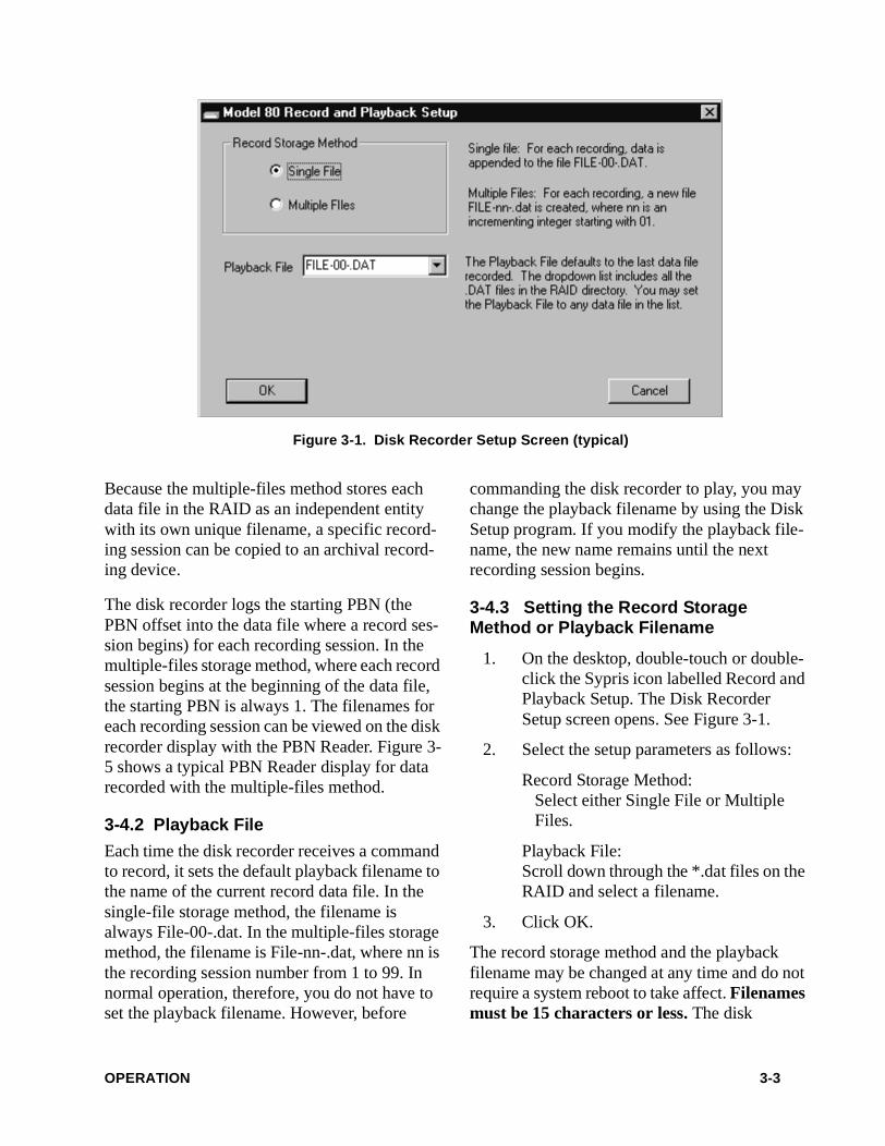
3-4.3 Setting the Record Storage Method or Playback Filename
1. On the desktop, double-touch or double-click the Sypris icon labelled Record and Playback Setup. The Disk Recorder Setup screen opens. See Figure 3-1.
2. Select the setup parameters as follows:
Record Storage Method: Select either Single File or Multiple Files.
Playback File: Scroll down through the *.dat files on the RAID and select a filename.
3. Click OK.
The record storage method and the playback filename may be changed at any time and do not require a system reboot to take affect. Filenames must be 15 characters or less. The disk
Figure 3-1. Disk Recorder Setup Screen (typical)
OPERATION 3-3
recorder reads the record storage method each time it receives a command to record. Each time the disk recorder receives a command to play, it reads the playback filename.
3-5 ARMOR CONTROL
The disk recorder can assume control of all ARMOR setup and operational functions through the ARMOR I Host software.
NOTE
If the disk recorder fails to com-municate with the ARMOR after power-up or if the ARMOR soft-ware appears to lock up, exit the ARMOR software, cycle ARMOR power, then restart the ARMOR software to restore nor-mal operation.
1. Ensure that the ARMOR unit is powered up (the Power indicator on the front panel is on).
2. Double-touch or double-click the ARMOR I HOST icon on the disk recorder touchscreen to activate the
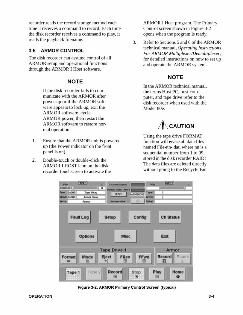
ARMOR I Host program. The Primary Control screen shown in Figure 3-2 opens when the program is ready.
3. Refer to Sections 5 and 6 of the ARMOR technical manual, Operating Instructions For ARMOR Multiplexer/Demultiplexer, for detailed instructions on how to set up and operate the ARMOR system.
NOTE
In the ARMOR technical manual, the terms Host PC, host com-puter, and tape drive refer to the disk recorder when used with the Model 80e.
CAUTION
Using the tape drive FORMAT function will erase all data files named File-nn-.dat, where nn is a sequential number from 1 to 99, stored in the disk recorder RAID! The data files are deleted directly without going to the Recycle Bin
Figure 3-2. ARMOR Primary Control Screen (typical)
OPERATION 3-4
and are therefore not recoverable! Do not attempt a FORMAT oper-ation unless you want to clear the disk array! Before using FOR-MAT, archive or save any files to be retained .
3-6 RECORDING ARMOR DATA
With minor exceptions, recording ARMOR out-put data to the disk recorder RAID is similar to recording data to a tape drive.
1. Verify all data connections between the user’s data I/O equipment and the ARMOR.
NOTE
Specific data connections for your particular ARMOR are detailed in the System Configura-tion Data in Appendix A of the ARMOR technical manual.
2. After system power-up and after the ARMOR I Host program is started, TAPE 1 operation is automatically acti-vated.
3. Ensure that the ARMOR setup is valid for the types of data you expect to record. Refer to Sections 5 and 6 of the ARMOR technical manual, Operating Instructions for ARMOR Multiplexer/Demultiplexer, for detailed descriptions of ARMOR setup parameters.
4. To clear the disk recorder RAID before you begin to record data, select Format on the primary control screen. The For-mat command deletes the single-file method data file (File-00-.dat) and all of the multiple-files method data files (File-nn-.dat, where nn is a sequential number from 1 to 99). It also sets the default playback filename to blank (no playback file) until the next recording session is initiated. When the Format button indi-cates it is again active (its background color lightens and the Format name on the button is green), the RAID is cleared.
Figure 3-3. ARMOR Play Mode Setup Screen (typical)
OPERATION 3-5
5. Ensure that the I/O equipment is provid-ing data to the ARMOR.
6. Select Record to start data recording.
The record operation will continue until RAID capacity is reached or the Stop button is selected.
NOTE
Status of the data transfer from the ARMOR to the RAID is indi-cated by changes in the PBN value shown on the Tape Monitor in the upper left corner of the ARMOR Primary Control screen.
The PBN reported by the disk recorder during recording reflects the PBN in the current data file. When recording with the single-file method, the starting PBN for a particular recording will therefore be the filesize in PBNs at the start of the current recording session. When record-ing with the multiple-files method, the starting PBN for a particular recording session will always be 1, because each session starts a new file.
The Percent Meter during recording reflects the percentage of the available disk space utilized by the current recorded data file; i.e., the ratio of the current filesize to the sum of the current filesize and the free space on the RAID. The Percent Meter does not consider disk space allocated to other files on the RAID, including previous files recorded in the multiple-files method.
3-7 PLAYING ARMOR DATA
With minor exceptions, playing data from the disk recorder RAID to the ARMOR (and back to other system equipment) is similar to playing data from a tape drive to the ARMOR.
Normally, when the disk recorder receives a command to play, it plays back data from the last data file recorded. However, you may use the Disk Setup program to change the playback file before starting the playback operation. See sec-tion 3-4, DISK SETUP, for detailed instructions on changing the playback filename.
1. Verify all data connections between the other system equipment and the ARMOR.
NOTE
Specific data connections for your particular ARMOR are detailed in the System Configura-tion Data in Appendix A of the ARMOR technical manual.
2. After the system is powered up and the ARMOR Software is activated, TAPE 1 operation is automatically activated.
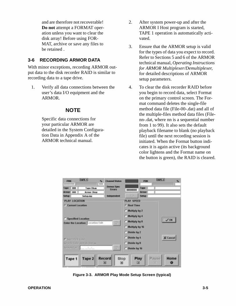
3. Select Play to open the Play Mode Setup screen, as shown in Figure 3-3.
4. Enter the desired data playback parame-ters (play location, play speed, etc.) on the Play Mode Setup screen.
5. After the play selections have been made, select OK to begin the data play-back operation.
When data playback begins, the Play but-ton becomes active (background color lightens and the PLAY nomenclature changes from black to green).
The data playback operation will con-tinue until the Stop command is selected or end-of-file is encountered.
NOTE
Status of the data transfer from the RAID to the ARMOR is indi-cated by changes in the PBN value shown on the Tape Monitor
OPERATION 3-6
in the upper left corner of the ARMOR Primary Control screen. The PBN reported by the disk recorder during playback indi-cates the PBN offset into the cur-rent data file. The Percent meter reflects the percentage of the playback file that has been played back.
If the ARMOR software displays the error message “Failure Set-ting Tape to Play”, check that the playback filename is correct. See section 3-4, DISK SETUP, for detailed instructions on changing (or checking) the playback file-name. Use Windows Explorer to check that the playback file exists on the RAID. If playing back from a specified location, verify that the specified location is within the bounds of the file.
3-8 ARCHIVING DATA
Data may be copied from the disk recorder RAID to any installed archival recording device. The methods used depend on the storage format that was in use when the data was recorded to the RAID and the type of device to which the data is being copied.
3-8.1 Using the PBN Reader
The PBN Reader is a software utility that lets you identify the recording sessions that comprise the ARMOR data currently stored in the disk recorder RAID.
On the desktop, double-touch or double-click the Sypris PBN Reader icon. The PBN Reader screen opens.
Typical PBN Reader displays for PBN Reader – Single-File Mode and PBN Reader – Multiple-Files Mode are shown in Figures 3-4 and 3-5, respectively. Note that the starting PBN for each recording session is listed.
The PBN Reader display is the same for both modes, except that in multiple-files mode, it lists the individual filename for each recording ses-sion currently stored in the RAID, in addition to the starting PBN.
3-8.1.1 Single-File Mode
When data is stored in single-file mode, all data in the RAID is stored under a single filename shown in the display screen header, as in Figure 3-4. Therefore, the PBN information shown on this screen serves no purpose when copying data to an archive drive; the complete file must be copied in its entirety.
NOTE
Although individual recording sessions cannot be archived in single-file mode, ARMOR setup information at the starting PBN for each session can be read by using the ARMOR Read Setup From Tape operation.
3-8.1.2 Multiple-Files Mode
For data stored in multiple-files mode, the auto-matically assigned filenames for each file in the disk array are listed in the Recorded Filename column on the screen, as shown in Figure 3-5. By using the filenames, you can transfer individ-ual sessions to storage devices.
3-8.2 Drive Identification
System drive (internal and accessible) devices are assigned logical drive identifications by default as follows:
a: 3.5-inch floppy diskette (rear panel)
b: Unassigned
c: NT/system application disk partition (NTFS) on the system hard drive
d: User disk partition (NTFS) on the system hard drive
e: RAID
OPERATION 3-7
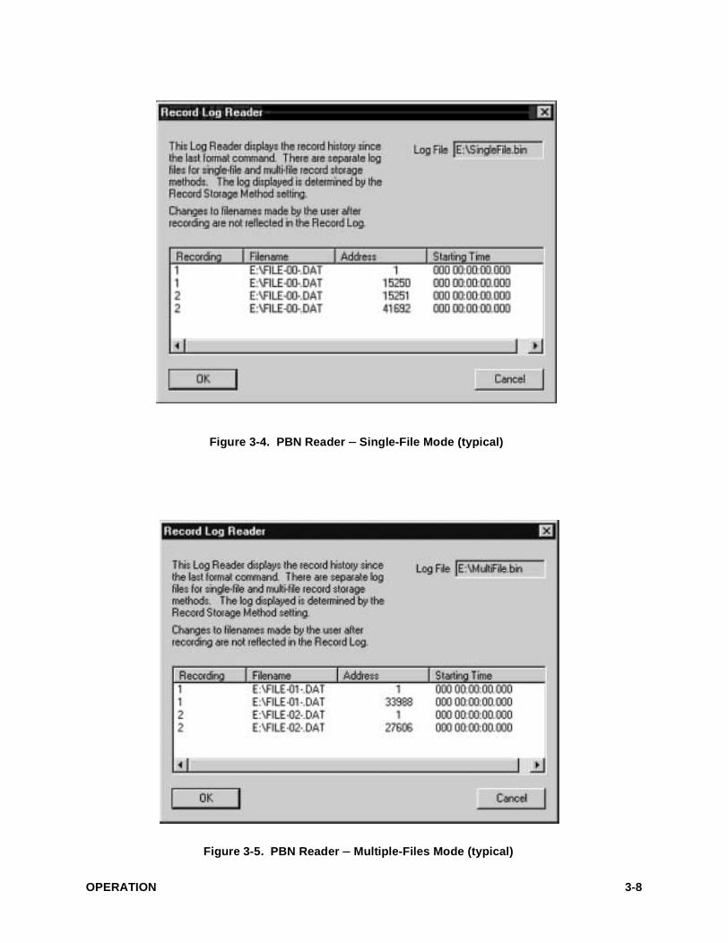
Figure 3-4. PBN Reader – Single-File Mode (typical)
Figure 3-5. PBN Reader – Multiple-Files Mode (typical)
OPERATION 3-8
f: DVD-RAM (front-panel)
g: CD-ROM, CD-R, CD-RW (front-panel)
h: Additional user disk partition on the sys-tem hard drive
3-8.3 DDS-4 or DLT (Digital Linear Tape) Drive
NOTE
Detailed operating information for the DLT drive is contained in the manufacturer’s documenta-tion supplied with your unit. Read this information before attempting to operate the drive.
The backup utility supplied with Windows NT® is used to archive data to and restore data from the DLT. Use of this utility is described in Win-dows NT® on-line (help) documentation, so it is not detailed here.
Generally, the process requires the following key steps:
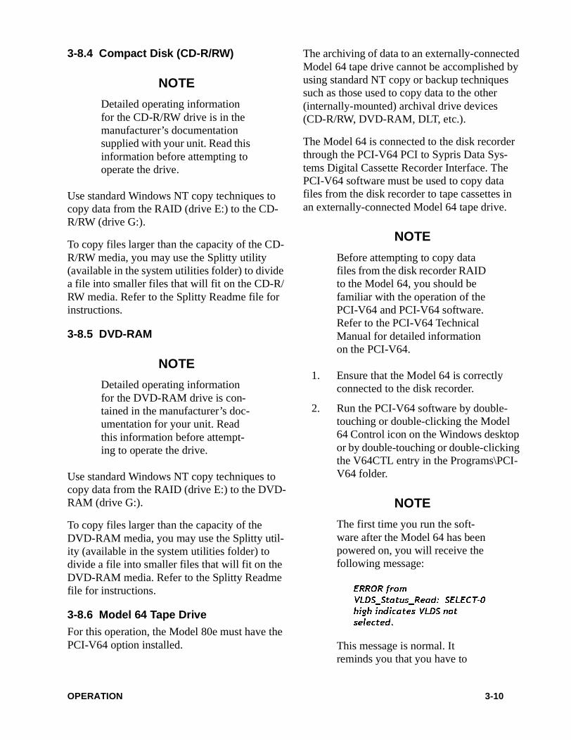
1. On the desktop, double-touch or double-click the Utilities Folder icon to open the Utilities window shown in Figure 3-6.
2. Double-touch or double-click the Backup icon to start the utility. The backup screen opens.
3. Select (maximize) the Drives screen.
4. Select the E: drive. The E: drive screen opens. This screen lists all files currently in the E: drive RAID.
5. Select the files to be backed up to the DLT drive. The files are highlighted and the checkbox is checked when a file is selected for backup.
6. Select BACKUP at the top of the screen to begin the backup process. A confirma-tion screen opens.
7. Enter the desired options on the confir-mation screen and select OK.
8. The backup status window is open while the data backup is in progress.
Figure 3-6. System Utilities Window (typical)
OPERATION 3-9
3-8.4 Compact Disk (CD-R/RW)
NOTE
Detailed operating information for the CD-R/RW drive is in the manufacturer’s documentation supplied with your unit. Read this information before attempting to operate the drive.
Use standard Windows NT copy techniques to copy data from the RAID (drive E:) to the CD-R/RW (drive G:).
To copy files larger than the capacity of the CD-R/RW media, you may use the Splitty utility (available in the system utilities folder) to divide a file into smaller files that will fit on the CD-R/RW media. Refer to the Splitty Readme file for instructions.
3-8.5 DVD-RAM
NOTE
Detailed operating information for the DVD-RAM drive is con-tained in the manufacturer’s doc-umentation for your unit. Read this information before attempt-ing to operate the drive.
Use standard Windows NT copy techniques to copy data from the RAID (drive E:) to the DVD-RAM (drive G:).
To copy files larger than the capacity of the DVD-RAM media, you may use the Splitty util-ity (available in the system utilities folder) to divide a file into smaller files that will fit on the DVD-RAM media. Refer to the Splitty Readme file for instructions.
3-8.6 Model 64 Tape Drive
For this operation, the Model 80e must have the PCI-V64 option installed.
The archiving of data to an externally-connected Model 64 tape drive cannot be accomplished by using standard NT copy or backup techniques such as those used to copy data to the other (internally-mounted) archival drive devices (CD-R/RW, DVD-RAM, DLT, etc.).
The Model 64 is connected to the disk recorder through the PCI-V64 PCI to Sypris Data Sys-tems Digital Cassette Recorder Interface. The PCI-V64 software must be used to copy data files from the disk recorder to tape cassettes in an externally-connected Model 64 tape drive.
NOTE
Before attempting to copy data files from the disk recorder RAID to the Model 64, you should be familiar with the operation of the PCI-V64 and PCI-V64 software. Refer to the PCI-V64 Technical Manual for detailed information on the PCI-V64.
1. Ensure that the Model 64 is correctly connected to the disk recorder.
2. Run the PCI-V64 software by double-touching or double-clicking the Model 64 Control icon on the Windows desktop or by double-touching or double-clicking the V64CTL entry in the Programs\PCI-V64 folder.
NOTE
The first time you run the soft-ware after the Model 64 has been powered on, you will receive the following message:
ERROR from
VLDS_Status_Read: SELECT-0
high indicates VLDS not
selected.
This message is normal. It reminds you that you have to
OPERATION 3-10
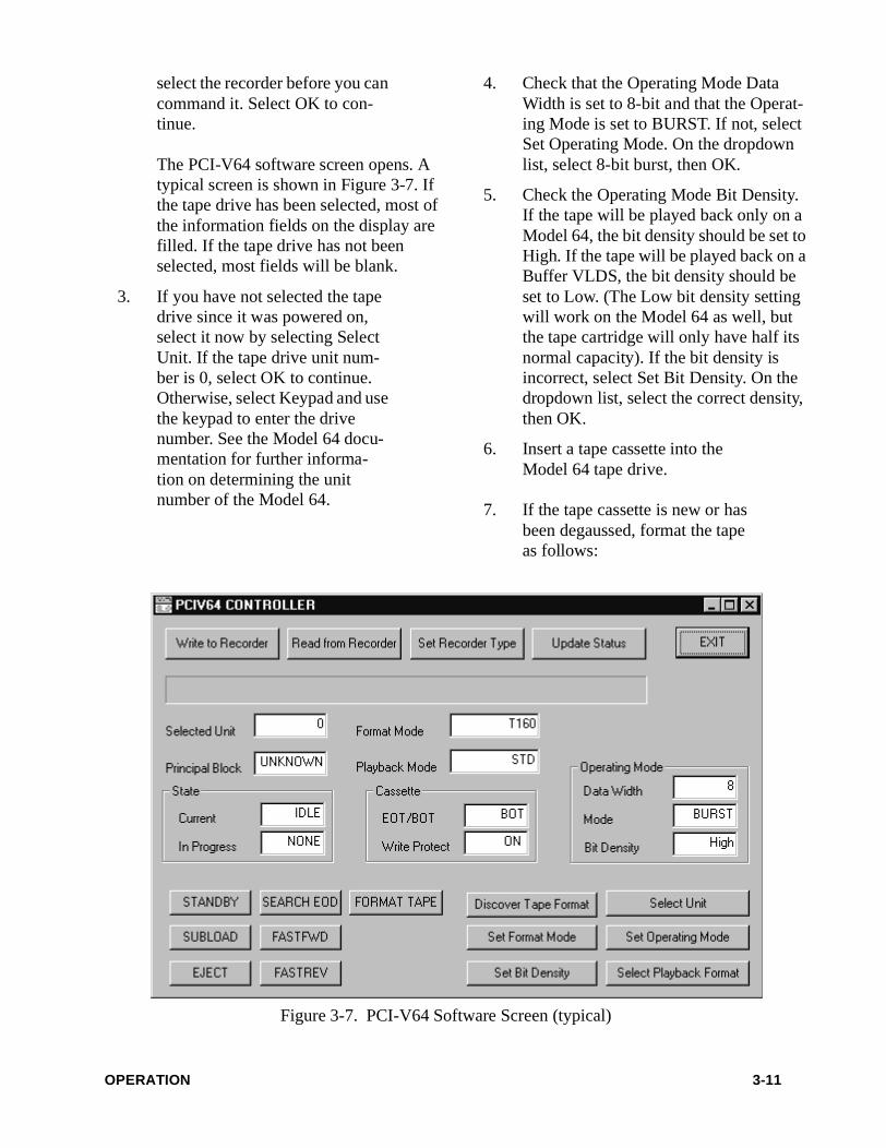
select the recorder before you can command it. Select OK to con-tinue.
The PCI-V64 software screen opens. A typical screen is shown in Figure 3-7. If the tape drive has been selected, most of the information fields on the display are filled. If the tape drive has not been selected, most fields will be blank.
3. If you have not selected the tape drive since it was powered on, select it now by selecting Select Unit. If the tape drive unit num-ber is 0, select OK to continue. Otherwise, select Keypad and use the keypad to enter the drive number. See the Model 64 docu-mentation for further informa-tion on determining the unit number of the Model 64.
4. Check that the Operating Mode Data Width is set to 8-bit and that the Operat-ing Mode is set to BURST. If not, select Set Operating Mode. On the dropdown list, select 8-bit burst, then OK.
5. Check the Operating Mode Bit Density. If the tape will be played back only on a Model 64, the bit density should be set to High. If the tape will be played back on a Buffer VLDS, the bit density should be set to Low. (The Low bit density setting will work on the Model 64 as well, but the tape cartridge will only have half its normal capacity). If the bit density is incorrect, select Set Bit Density. On the dropdown list, select the correct density, then OK.
6. Insert a tape cassette into the Model 64 tape drive.
7. If the tape cassette is new or has been degaussed, format the tape as follows:
Figure 3-7. PCI-V64 Software Screen (typical)
OPERATION 3-11

a. The tape drive state must be SUBLOAD to format a tape. Select Update Status to update the Current State of the tape drive. If the tape drive is not in SUBLOAD, select SUBLOAD.
b. Select Set Format Mode. On the dropdown list, select the proper format for your tape capacity (T120 No Dir Chan-nels or T160 No Dir Chan-nels).
c. Select Format Tape. Enter a volume label or accept the default of 0. Select OK to start the formatting. Wait 30 seconds for the formatting to finish. When formatting is complete, the tape drive Cur-rent State should be STANDBY.
8. Select Write To Recorder to begin the copy operation.
9. The Open window opens. Use this win-dow to select the device, directory, and filename to copy. Use the down arrow in the Look In dropdown list to display the disks and directories. The RAID is nor-mally designated as device E. Select E to display the files in the RAID data direc-tory. Select the file that you wish to copy and select Open to complete the selec-tion.
10. The Confirm Transfer window opens. Select OK to confirm the transfer.
11. The Model 64 will search to the end of the recording to determine the starting PBN of this recording. When the PCI-V64 Software displays the starting PBN, select OK to begin the copy operation.
Progress of the copy operation is indi-cated by the progress bar at the top of the PCI-V64 window. The PCI-V64 soft-ware notifies you when the copy is com-plete.
NOTE
To copy files larger than the capacity of the Model 64 media, you may use the Splitty utility (available in the System Utilities folder) to divide a file into smaller files that will fit on the Model 64 media. Refer to the Splitty Readme file for instruc-tions.
CAUTION
To abort the write operation before the file transfer is com-plete, select Cancel. If the Cancel button is not operative and you have a mouse connected to the disk recorder, go to the Windows Task Manager and end the V64CTL process to abort the operation. Open the Task Man-ager by right-clicking a blank area in the Taskbar at the bottom of the screen.
12. To eject the tape from the Model 64, the tape drive must be in the SUBLOAD state. If the Current State of the Model 64 is not SUBLOAD, select SUBLOAD. To eject the tape, select EJECT.
OPERATION 3-12
3-9 NETWORK OPERATION
3-9.1 Network Setup
To establish network communications, the disk recorder must be properly configured.
CAUTION
All required network support software is installed at the fac-tory. A network administrator must assign a static IP Address and manually set the TCP/IP properties as described below. Do not use DHCP, which auto-matically assigns IP addresses. You are strongly advised to sus-pend all network operations on the disk recorder during record and playback sessions.
1. On the desktop, right-click the Network Neighborhood icon.
2. On the Network screen, select the Proto-cols tab.
3. On the Protocols screen, select TCP/IP, then select Properties.
4. On the TCP/IP Properties screen, enter the appropriate IP Address, Subnet Mask, and Default Gateway values for your network.
When the correct values are entered, select OK to re-display the Network screen.
5. On the Network screen, select Close.
6. At this point, you are instructed to reboot the system so the new network settings can be recognized. Select Yes to reboot.
7. After the system reboots, you may verify your network setup as follows:
a. Select the MSDOS icon to open a DOS window.
b. Use the Ping command to ping a known network address (example: C:\ping 198.59.17.54).
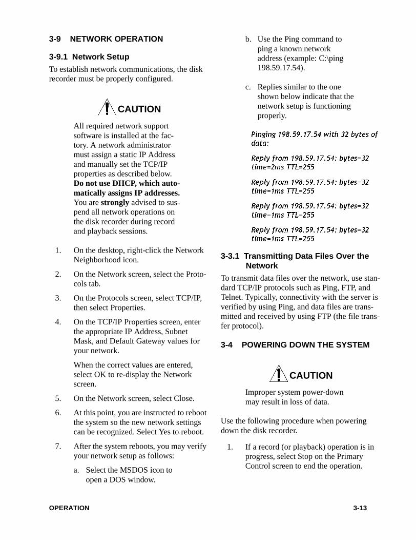
c. Replies similar to the one shown below indicate that the network setup is functioning properly.
Pinging 198.59.17.54 with 32 bytes of
data:
Reply from 198.59.17.54: bytes=32
time=2ms TTL=255
Reply from 198.59.17.54: bytes=32
time=1ms TTL=255
Reply from 198.59.17.54: bytes=32
time=1ms TTL=255
Reply from 198.59.17.54: bytes=32
time=1ms TTL=255
3-3.1 Transmitting Data Files Over the Network
To transmit data files over the network, use stan-dard TCP/IP protocols such as Ping, FTP, and Telnet. Typically, connectivity with the server is verified by using Ping, and data files are trans-mitted and received by using FTP (the file trans-fer protocol).
3-4 POWERING DOWN THE SYSTEM
CAUTION
Improper system power-down may result in loss of data.
Use the following procedure when powering down the disk recorder.
1. If a record (or playback) operation is in progress, select Stop on the Primary Control screen to end the operation.
OPERATION 3-13
2. Select Exit on the Primary Control screen to exit the ARMOR software and return to the Windows desktop.
3. Select the Start button in the taskbar, then select Shut Down from the pop-up menu. The Shut Down Windows dialog box opens.
When prompted with “Are you sure you want to: Shut down the computer?”, select Yes.
The Windows NT Workstation® signa-ture screen will be displayed for a time, followed by the message, “Please wait while the system writes unsaved data to the disk.”
CAUTION
To ensure against data loss, do not remove power from the disk recorder until you see the mes-sage, “It’s now safe to turn off your computer.”
4. When the message, “It’s now safe to turn off your computer.” is displayed, you may turn the disk recorder OFF.
OPERATION 3-14

This page intentionally left blank.
SECTION 4
MAINTENANCE
4-1 GENERAL
This section has two subsections:
• Routine Maintenance
This subsection provides general cleaning procedures and instructions for packing the disk recorder for shipment.
• Corrective Maintenance
This subsection is intended for qualified persons such as service technicians and system administrators, who are experi-enced in installing software and servicing workstations.
WARNING
The disk recorder contains dan-gerous high voltages and no user-serviceable internal components. To avoid personal injury, always disconnect the disk recorder from the power source before remov-ing any cover.
CAUTION
This equipment contains ESDS devices. Proper ESDS device handling procedures must be fol-
lowed. Refer to the ESDS DEVICE HANDLING informa-tion at the front of this manual.
4-2 ROUTINE MAINTENANCE
This subsection provides routine maintenance information. It covers external cleaning, touch-screen cleaning, and packaging the disk recorder for shipment.
4-2.1 External Cleaning
Clean the external surfaces on the disk recorder (as required) as follows:
1. Turn disk recorder power OFF and dis-connect the power cord.
2. Use a lint-free cloth dampened with a mild commercial cleaning agent to wipe down the exterior surfaces of the disk recorder. Do not clean the touchscreen with this cleaning agent. See paragraph 4-2.2 for touchscreen cleaning.
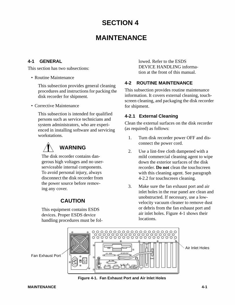
3. Make sure the fan exhaust port and air inlet holes in the rear panel are clean and unobstructed. If necessary, use a low-velocity vacuum cleaner to remove dust or debris from the fan exhaust port and air inlet holes. Figure 4-1 shows their locations.
Air Inlet Holes
Fan Exhaust Port
Figure 4-1. Fan Exhaust Port and Air Inlet Holes
MAINTENANCE 4-1
4-2.2 Cleaning the Touchscreen
When required, the touchscreen may be cleaned as follows:
1. Turn disk recorder power OFF and dis-connect the power cord.
2. Use a clean lint-free cloth dampened with an ammonia-based glass cleaner or denatured alcohol and carefully wipe the touchscreen. Use light pressure to pre-vent scratching the touchscreen. If a spray applicator is used, spray the cloth only – do not spray directly on the touchscreen.
4-2.3 Packaging the Disk Recorder for Shipment
If the original shipping carton and packing mate-rials are available, they should be reused when packaging the disk recorder for shipment. If they are not available, use the following procedure.
NOTE
If available, the original shipping carton and packing materials should be reused when packaging the disk recorder for shipment.
1. Disconnect all interconnecting and power cables from the rear of the disk recorder.
2. Disconnect the three cables that extend through the rear panel from connectors J1, J2, J7, and COM3. This prevents the connectors and system board from being damaged during shipment.
3. Make sure there is no diskette in the 3.5-inch floppy drive on the rear panel.
4. Remove all media from the front-panel archival drives.
5. Ensure that all internal assemblies are properly secured and all internal cables are connected (no loose assemblies).
6. Enclose the disk recorder in an ESD-pro-tective plastic bag.
7. Place the disk recorder in a heavy-duty corrugated cardboard carton having slightly larger dimensions than the unit.
8. Using a packing material that will not settle or deform, pack all sides of the disk recorder so all voids are filled.
Seal the carton and place it in an extra-strength outer carton. The outer carton must be large enough to allow room for a minimum of two inches of packing mate-rial on each side of the inner pack.
9. Insert packing material tightly between the inner and outer cartons.
10. Seal the outer carton and mark it FRAG-ILE, DO NOT DROP, and THIS SIDE UP.
4-3 CORRECTIVE MAINTENANCE
This sub-section provides special instructions for qualified persons such as service technicians and system administrators who are familiar with installing software and servicing workstations. It includes information for upgrading software and replacing the system disk, and it provides gen-eral instructions for installing archival recording devices in the front-panel drive bays.
CAUTION
The following instructions are intended only for service techni-cians and system administrators who are familiar with installing software and servicing worksta-tions.
MAINTENANCE 4-2

4-3.1 Reinstalling and Upgrading Software
4-3.1.1 General
All disk recorders are shipped from the factory with a complete suite of application and device driver software installed to support all the installed devices. Backup media are provided for installed software.
Because the software suite provides basic work-station operations as well as disk recorder func-tionality, there are complex configuration requirements for the proper integration of the numerous, diverse programs that make up the suite (e.g.; operating system, applications, device drivers, utilities, etc.). These require-ments make reinstalling certain software appli-cations impractical because of the potential for system conflicts that can make the disk recorder unusable.
Generally, only factory-authorized software upgrades, or a reinstallation of a specific appli-cation under the direct supervision of a factory technical support representative, should be attempted.
4-3.1.2 Upgrading Software
Upgrades may be released to support operational enhancements to the ARMOR or the disk recorder. In most cases, software upgrade kits will consist of a set of distribution diskettes and detailed installation instructions.
An upgrade is typically installed by inserting the distribution diskettes into the rear-panel diskette drive, then copying the *.exe file to the control program directory on the system drive (C:) as detailed in the supplied instructions. The previ-ous *.exe file will be replaced with the upgraded *.exe file provided on the distribution diskette.
4-3.2 Installing Archival Drives in Front-panel Drive Bays
NOTE
Disk recorders are delivered in various configurations that may contain archival recording devices. If a different or addi-tional archival drive is to be installed, the drive and the disk recorder should be returned to Sypris Data Systems for recon-figuration. This is the only method that guarantees continued warranty support. Contact your Sypris Data Systems representa-tive for information.
CAUTION
Installing an archival drive in an existing disk recorder requires, as a minimum, disassembling vari-ous chassis parts, connecting cables, and installing software driver programs. Depending upon the type of drive, installation may also require removing plug-in cir-cuit cards to gain access to cable connectors on the system board, and reselecting IRQ and address settings.
Because of the complexity of some of these tasks, there is potential for equipment damage or software operating system and application conflicts that may result in faulty operation of the archive drive or disk recorder. Sypris Data Systems may not assume warranty responsibility for damage caused by users installing an internal archive drive.
MAINTENANCE 4-3

The disk recorder accommodates various remov-able-media drive assemblies in its front-panel drive bays. In general, any combination of drive types that can fit into the three 5.25-inch half-height drive bays may be installed.
Factory-configured disk recorders are available with various archival drive devices installed (refer to the model code information in Section 1). Other, third-party drives, not offered by Syp-ris Data Systems, may also be usable with the disk recorder. If you elect to install a third-party device, please refer to the manufacturer’s instal-lation instructions.
CAUTION
Installing a drive in a front-panel drive bay involves disassembling the disk recorder chassis assem-bly and connecting data and power cabling. For third-party drives, it might also require installing driver software. If you are not familiar with these tasks, you should refer the drive instal-lation to a qualified technician.
MAINTENANCE 4-4
Sypris Data SystemsTechnical Support
In U.S.A.: 1-800-937-9220International: 1-626-930-9444
6:00 a.m. – 6:00 p.m. (GMT)Monday – Friday
Sypris Data Systems605 East Huntington DriveMonrovia, CA 91016-3636
http://www.syprisdatasystems.com